

Page 1

3G4010 V4.0/LE4010 V5.0
3G (HSPA) Cellular Alarm Communicator
LTE Wireless Alarm Communicator
INSTALLATION MANUAL
Warning: This manual contains information on limitations regarding product use and function and information on the limitations as to liability of
the manufacturer. The entire manual should be carefully read.
Page 2

Contents
Section 1: Introduction 6
1.1 Features 6
1.1.1 Technical Specifications 7
1.2 Identification of Parts 9
Section 2: Installing the 3G4010/LE4010 10
2.1 C24 Communications Enrollment 10
Section 3: Connecting the 3G4010/LE4010 13
Section 4: Status LEDs 14
4.1 Operating Modes 14
4.1.1 Normal Mode 14
4.1.2 Service Mode 14
Section 5: Operating Principles 16
5.1 Simulated Landline Mode 16
5.2 Panel Transmission Monitoring (PTM) 16
5.3 Cellular Communications Sequence 16
5.4 Inputs 17
5.5 Outputs 17
5.5.1 Activating the Outputs 17
5.6 Reporting Codes 18
5.7 Swinger Shutdown 19
5.8 Hardware Default 19
5.9 Communicator Reset/Update 19
5.10 Low Power Radio Shutdown 20
5.11 SMS Command and Control 20
5.11.1 Arming/Disarming the Security Panel 20
5.11.2 Remote Control of PGM 20
5.12 Phone Number Call Direction 21
5.13 C24 Communications Remote Programming 22
Section 6: Troubleshooting Guide 23
6.1 LE4010 IM Wiring Diagrams 27
Page 3
3G4010/LE4010 Installation Manual
Safety Information
IMPORTANT: The equipment is fixed, wall-mounted and shall be installed in the position specified in these
instructions (see Figure 1: Parts). The equipment enclosure must be fully assembled and closed, with all the
necessary screws/tabs and secured to a wall before operation. Internal wiring must be routed in a manner that
prevents:
- Excessive strain on wire and on terminal connections
- Loosening of terminal; connections
- Damage of conductor insulation
Never install this equipment during a lightning storm!
Instruct the end-user to:
- Not attempt to service this product. Opening or removing covers may expose the user to dangerous voltages
or other risks. Any servicing shall be referred to trained service persons only.
- Use authorized accessories only with this equipment.
Do not dispose of the battery in fire or water. Disposing of the battery in a fire will cause rupture and explosion.
Do not dispose of the waste battery as unsorted municipal waste. Consult your local regulations and /or laws
regarding recycling with regard to this lead-acid battery. Doing so will help protect the environment. Some of
the materials that are found within the battery could become toxic if not disposed of properly and may affect
the environment.
This equipment, 3G4010/LE4010, is fixed and shall be installed by Service Persons only (Service Person is
defined as a person having the appropriate technical training and experience necessary to be aware of hazards
to which that person may be exposed in performing a task, and of measures available to minimize the risks to
that person or other persons). It shall be installed and used within an environment that provides the pollution
degree max 2, over voltages category II, in non-hazardous, indoor locations only. This manual shall be used
with the Installation Manual of the relevant alarm control panel. All instructions specified within that manual
must be observed.
The performance of the 3G4010/LE4010 depends greatly on cellular network coverage. Therefore, it should
not be mounted without first performing placement tests to determine the best location for reception (minimum
of one green LED ON). Optional antenna kits – LTE-8ANT, LTE-15ANT, LTE-25ANT, LTE-50ANT
(8ft/2.4m, 15ft/4.6m, 25ft/7.6m or 50ft/15.2m) – are available.
Approvals Information
NOTICE TO USERS, INSTALLERS, AUTHORITIES HAVING JURISDICTION AND OTHER
INVOLVED PARTIES
This product incorporates field-programmable software. In order for the product to comply with the requirements in the Standard for Control Units and Accessories for Fire Alarm Systems, UL 864, certain programming
features or options must be limited to the specific values or not used at all as indicated below.
Permitted
Program Feature or Option
Supervision Yes 5 minutes /60 minutes 5 minutes (see note below)
Inputs/Outputs Yes Fire/Burg signals Fire r elated signals only
SMS Remote Control No Enable/Disable Disable
Note: This product has been tested in accordance with UL 864 9th edition. According to this edition of the
standard, the supervision window for reporting single-technology communicator trouble shall be set to five
minutes. However, the product can be installed in accordance with the requirements of NFPA72 2013 edition,
which allows for a 60-minute supervision window.
in UL 864
(Y/N?)
Possible Settings Settings Permitted in UL 864
3
Page 4

Note: Encryption shall be enabled for active communications.
Notes for using Private, Corporate and High Speed Data Networks: Network access and domain access
policies shall be set to restrict unauthorized network access, and "spoofing" or "denial of service" attacks.
Select the internet service providers that have redundant servers/systems, back-up power, routers with firewalls
enabled and methods to identify and protect against "denial of service" attacks (i.e., "spoofing").
For UL Residential Fire and Burglary installations, the 3G4010/LE4010 is listed as a sole means of communication or as a back up when used in conjunction with a POTS line (dialer).
For UL Commercial Burglary installations, the 3G4010/LE4010 is listed as a sole means of communication
(supervision window of 200s required at monitoring station) or as a back-up when used in conjunction with a
POTS line (dialer). The 3G4010/LE4010 shall be powered from any compatible listed control unit or com-patible listed power supply that complies with the ratings specified on page 1. The power supply shall be lis-ted
for burglary applications and provide a minimum of 4 hours standby power capabilities. An example of a suitable listed compatible control unit is the DSC Model HS2128 with an AUX output rated 11.1 - 12.6VDC. An
example of a suitable Listed power supply is DSC Model HSM2204 with an AUX output rated 11.6 -
12.6VDC.
For ULC Commercial Fire Monitoring Installations, the 3G4010/LE4010 can be used in the following configurations:
1. Active communication system with 180 seconds supervision and heartbeat sent to signal receiving center every 90 seconds (encryption shall be enabled).
2. Passive communication system in conjunction with a another communication path (e.g. DACT) (there is
no heartbeat sent in this configuration, only periodic test transmission ).
Alarm signals must be sent simultaneously over both communication paths (Cellular and DACT). Every
24 hours, a test transmission must be sent to the signal receiving center over each communication path.
Each communication path shall be monitored for integrity (DACT shall have line monitoring enabled
and 3G4010/LE4010 shall have cellular connection supervision enabled).
3. The unit shall be powered by ULC Listed Control Unit or power supply rated for the application. All
interconnections are restricted to same room, maximum 18 meters in metallic conduit.
For ULC Commercial Burglary Monitoring Installation the 3G4010/LE4010 can be used in the following
configurations:
1. Active communication system with 180 seconds supervision and heartbeat sent to signal receiving
centre every 90 seconds (encryption shall be enabled).
2. Passive communication system line security P1 (single communication channel) or line security P2
(used as backup in conjunction with another communication path (e.g. DACT)). There is no heartbeat
sent in this configuration, only periodic test transmissions.
Every 24 hours, a test transmission must be sent to the signal receiving centre over each communication
path. Each communication path shall be monitored for integrity (DACT shall have line monitoring
enabled and 3G4010/LE4010 shall have cellular connection supervision enabled). For Level P2, the
working communication path shall report the failure of the other channel within 240 seconds. The
LE4010 can be used in commercial burglary applications up to Security Level IV.
For ULC Residential Fire and Burglary installations, the 3G4010/LE4010 is listed as a sole means of communication or as a back up when used in conjunction with a POTS line (dialer).
For UL Commercial Fire Monitoring Installations, the LE4010 can be used in the following configurations:
1. Standalone communicator, single communication technology - 5 minute supervision (heartbeat sent to
supervising station every 90 seconds).
2. Back-up communicator line for a DACT (dual communication technology, no heartbeat sent). Alarm signals must be sent first over the primary communication path (DACT) and then, if this is known to have
failed, over the secondary communication paths (other transmission technologies).
4
Page 5

3G4010/LE4010 Installation Manual
l Primary: Compatible listed control unit's land line to central station (primary).
l Secondary: LE4010 transmission through wireless network to central station.
Every 24 hours, a check-in signal must be sent to the central station over the primary dialer. The LE4010 sends
a heartbeat test transmission to the supervising station every 24 hours. Each communication path shall be monitored for integrity (DACT shall have line monitoring enabled and LE4010 shall have cellular connection
supervision enabled).
Power for model LE4010 shall be provided by one of the two compatible power supplies:
a. Mircom Model – DTC-300A(W)(R), digital alarm communicator transmitter
b. Simplex control panel 4100U with converter module 4100-5152 installed
Note: Wiring between the LE4010 and FACP/Power Supply shall be made in the same room, in metal conduit
and not longer than 20ft.
5
Page 6

Section 1: Introduction
Section 1: Introduction
This manual covers two communicator models, the 3G4010 and the LE4010. They are referred to throughout
this manual as 3G4010/LE4010 unless otherwise indicated.
This 3G4010/LE4010 manages transmissions to a central station and can simulate the landline in the event of
trouble (e.g., landline down) or even substitute the landline completely in areas where the LTE/3G or 2G cellular service is provided and a landline is not available.
By connecting to a control panel's standard PSTN interface, telephone-based Contact ID or SIA signals are
decoded and seamlessly routed through the LTE, 3G or 2G network to any of the compatible receiver options.
Both models send alarm system information to a Sur-Gard System I-IP, II, III, IV or 5 receiver. The 3G4010
uses the 3G (HSPA) or 2G (GPRS) cellular network. The LE4010 uses the LTE or 3G wireless network. The
3G4010/LE4010 can be used with UL/ULC Listed compatible control units, as indicated in the manufacturer's
installation instructions.
Note: These communicators are designed to work with the Contact ID communication format as described in
the SIA DC-05 standard and the SIA DC-03 standard for 300 baud. Before completing the field installation of
the alarm monitoring system please ensure communication with the supervising central station is successful by
sending several events and getting confirmation that they have been received.
1.1 Features
l Dual-band UMTS/HSPA; Penta-Band LTE (LE4010); Quad-Band GSM/EDGE Radio
l Advanced Carrier Selection
l Bi-color Wireless Signal Strength Indicator
l 3G (HSPA) / 2G (GPRS) ; LTE or 3G (LE4010) Internet communication with Sur-Gard SG-System I-IP
/ II / III / IV / 5
l Compatible with 4-digit or 10-digit Contact ID communication format as described in SIA DC-05
Standard and the SIA DC-03 standard for 300 baud. Example of suitable compatible alarm panels:
DSC Models PC1864, PC1832, PC1616, PC4020. For LE4010, the following alarm panels are also compatible: HS2128, HS2064, HS2032, HS2016
l Panel Transmission Monitoring for up to four phone numbers
l Simulates landline
l Switches automatically to the 3G (HSPA) or 2G (GPRS) / LTE or 3G (LE4010) network in the event of
landline trouble (e.g., line down)
l Four Programmable (NO/NC/SEOL) Inputs
l 12V 1.2Ah battery (optional, not included)
l Case Tamper Output
l Landline overvoltage protection
l Four Programmable Outputs
l DLS support for status, firmware updates and remote debug enable
l Remote Firmware Upgrade
l Remote Diagnostics
l Panel Format Detection
l SMS Command and Control
l Phone number call direction
l Easy enrollment with C24 Communications via web or mobile interface
6
Page 7

3G4010/LE4010 Installation Manual
1.1.1 Technical Specifications
The input voltage to the 3G4010/LE4010 can be drawn from the UL/ULC Listed control panel or provided by
an external UL/ULC Listed power supply rated for the application (external power-limited source).
Note: The power supply must be Class 2, Power Limited. For residential applications a suitable power adaptor
is model DSC ADP1310(W)-NAU or DSC ADP1320-NAU (for USA) and model DSC ADP1310(W)-NA (for
Canada).
Table 5-1 Ratings
Power Supply Ratings
Input Voltage:
Current Consumption
Average Current (standby with PSTN
connected):
Average Current (standby without
PSTN connected):
Transmission Curr ent (no battery): 225mA*
* Plus any current drawn from the 3G4010/LE4010 AUX+ terminal. Each of the four PGM outputs can be loaded up to 50mA max)
Working Voltage Range
With Battery: (when power is provided by the external power adapter) 11-14Vdc
Without Battery: 9 -14Vdc
Battery T ype:
Battery charging voltage: 13.75Vdc
Battery charge curr ent limit: 360mA
NOTE: Battery must be replaced every 3-5 years.
NOTE: When using the battery, use DSCADP 1310-NAU(W) or ADP 1320-NAU power adapter
9-14Vdc (use separately listed control panel or power supply) or use DSC ADP1310(W)-NAx or
ADP1320-NAx power adapter with battery 12V/1.2Ah
40mA*
55mA*
sealed, rechargeable type, rated 12V/1.2Ah
(for 24hr standby time)
Operating frequency - 2G
(GSM/GPRS/E DGE):
Operating frequency - 3G
(UMTS/HSPA):
For LE4010 operating frequencies, see
table below.
Antenna gain: 2.0dBi
Environmental Specifications
Operating temperature: 0°C-49°C (32°F-120°F)
Humidity: 93%RH Maximum (non-condensing)
Mechanical Specifications
Dimensions (metal enclosure, painted): 138mm x 224mm x 55mm / 5.4” x 8.8” x 2.2”
850/1900MHz
850/1900MHz
7
Page 8
1.1.1 Technical Specifications
Weight (without battery): 900g / 3.2oz
Simulated Telco Loop specif ications (TIP/RING)
On-Hook Voltage: 12Vdc
Off-Hook Voltage (Maximum): 22Vdc
Loop Current : 25mA
Loop Resistance : 600 Ohms
Alternate construct ion
Dimensions (enclosure for
3G4010/LE4010):
Weight (alter nate construction enclosure
without batter y):
Table 5-2 LE4010 Operating Frequencies
Band Transmit Band (Tx) Receive Band (Rx)
LTE B2 1850 - 1910 MHz 1930 - 1990 MHz
LTE B4 1710 - 1755 MHz 2110 - 2155 MHz
LTE B5 824 - 849 MHz 869 - 894 MHz
LTE B12 698 - 716 MHz 728 - 746 MHz
LTE B13 777 - 787 MHz 746 - 756 MHz
UMTS B2 1850 - 1910 MHz 1930 - 1990 MHz
UMTS B5 824 - 840 MHz 869 - 894 MHz
138mm x 257mm x 55mm / 5.4" x 8.8" x 2.2"
1300g / 2.8lbs
8
Page 9
CON3
LED2
BAT +
OPE N
+
LED1
BAT -
-
LED4
LED3
UA673
SE
R
IAL NU MB E R
1
44
5
3
2
8
6
9
10
11
13
12
15
14
4
tie wrap
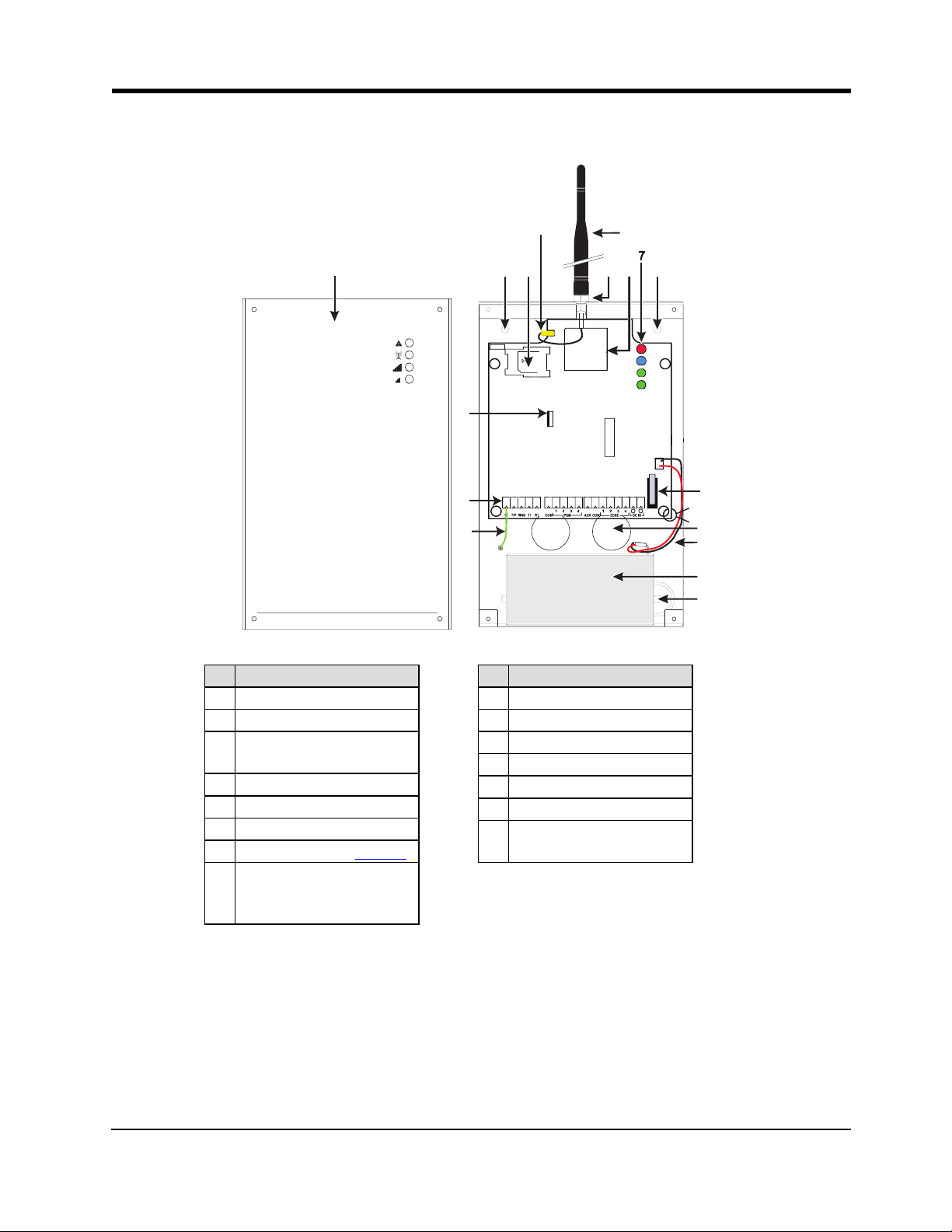
3G4010/LE4010 Installation Manual
1.2 Identification of Parts
Part
1 Metal Casing
2 3G/LTE Antenna
Antenna Mounting Hard-
3
ware
4 Anchor Screw Holes (3mm)
5 Antenna Connector
6 SIM Card Holder
7 Status LEDs (see page 14)
8
(3G4010); LTE Radio Mod-
3G (HSPA) Radio Module
9 PC-Link Connector
10 Tamper Switch
11 Terminal Blocks
12 Battery Leads
13 Cable Entry
14 Earth Ground Wire
15
12V/1.2Ah Battery
Part
(not included)
ule (LE4010)
9
Page 10
Section 2: Installing the 3G4010/LE4010
Section 2: Installing the 3G4010/LE4010
2.1 C24 Communications Enrollment
The 3G4010/LE4010 requires enrollment with C24 Communications to operate. For more information, please
visit www.connect24.com, contact C24 Communications customer service at 1-888-251-7458 (US) / 1-888955-5583 (Canada) or contact the central station to inquire if they are a C24 Communications Master Reseller.
Note: Enrollment with C24 Communications should be performed before turning on the 3G4010/LE4010 unit.
Before inserting or removing the SIM card, please ensure the unit is turned off.
Step 1 - Initialize the 3G4010/LE4010 with C24 Communications
The 3G4010/LE4010 can be initialized with C24 Communications by:
web - www.connect24.com
mobile - m.connect24.com
To complete enrollment, a C24 profile, installer ID/PIN (or web credentials) and the 20-digit SIM number are
required.
Note: The SIM activation process with the cellular carrier typically takes between five and ten minutes to complete.
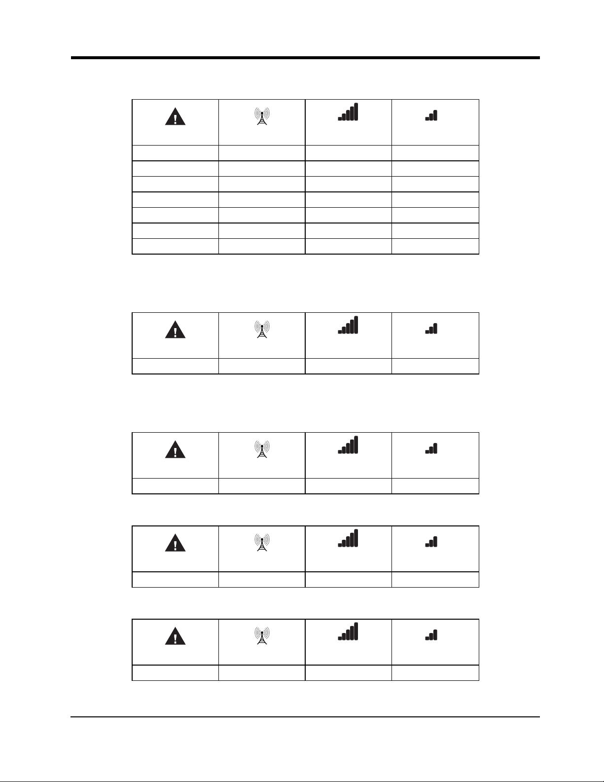
Step 2 - Determine the Best Signal Location
1. Detach the front cover by removing the four screws.
2. Apply power (DC and/or battery). The 3G4010/LE4010 is now in Placement Test mode.
Step 2a – SIM Card Is Activated.
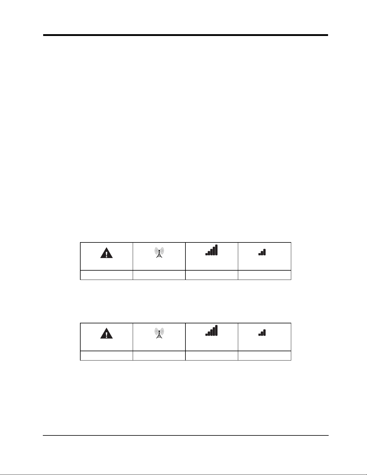
The red LED is on solid, the blue LED is off and the signal strength LEDs display the average signal strength.
In this state, the 3G4010/LE4010 is registered to the network.
Red Blue
ON OFF - -
Yellow/Green
(Top)
Yellow/Green
(Bottom)
If the signal strength is too low (bottom signal LED off or flashing), the 3G4010/LE4010 will proceed to Step
3: scan for, and attach to, carriers with sufficient signal strength. If the 3G4010/LE4010 is connected to a car-
rier with sufficient signal strength (minimum of bottom signal strength LED on solid), it proceeds to Step 4.
Step 2b – SIM Card Is Not Activated
The red LED flashes, the blue LED is off and the signal strength LEDs display the average signal strength.
Red Blue
FLASHING OFF - -
Yellow/Green
(Top)
Yellow/Green
(Bottom)
In this state, the 3G4010/LE4010 is unable to register to the network because it is inactive. The signal strength
indicated is from any nearby cell tower (including cellular towers belonging to non-roaming partners) and
does not necessarily reflect the signal strength of the intended network. The 3G4010/LE4010 remains in this
state until the SIM is activated. Once the SIM is activated, the 3G4010/LE4010 proceeds to Step 2a.
Step 3 – Carrier Scanning Due To Insufficient Signal Strength
The 3G4010/LE4010 scans the surrounding network and connects to the carrier to provide a signal strength of
at least 7 CSQ. While this action is being performed, all four LEDs activate to show a scanning sequence in
10
Page 11
3G4010/LE4010 Installation Manual
progress. The LEDs cycle from top to bottom and then bottom to top until the 3G4010/LE4010 connects to a
carrier with a signal strength above 7 CSQ (minimum of bottom signal strength LED on solid).
Red Blue
FLASH ON OFF OFF OFF
OFF FLASH ON OFF OFF
OFF OFF FLASH ON OFF
OFF OFF OFF FLASH ON
OFF OFF FLASH ON OFF
OFF FLASH ON OFF OFF
FLASH ON OFF OFF OFF
Yellow/Green
(Top)
Yellow/Green
(Bottom)
Once this is completed, the 3G4010/LE4010 proceeds to Step 4.
Step 4 - Acquire C24 Communications Programming
The red LED is on solid and the blue LED flashes. The flashing blue LED indicates that the 3G4010/LE4010
has requested programming from C24 Communications and is waiting for a response.
Red Blue
ON FLASHING - -
Yellow/Green
(Top)
Yellow/Green
(Bottom)
Once remote programming is completed, the blue LED switches to solid and the 3G4010/LE4010 proceeds to
Step 5.
Step 5 – Receiver Initialization
The red and blue LED’s are both on solid and the signal strength LEDs are off.
Red Blue
ON ON OFF OFF
Yellow/Green
(Top)
Yellow/Green
(Bottom)
When the 3G4010/LE4010 sends a request to communicate with the central station, the top signal strength
LED begins flashing.
Red Blue
ON ON FLASHING OFF
Yellow/Green
(Top)
Yellow/Green
(Bottom)
When the central station communicates back to the 3G4010/LE4010, the top signal strength LED turns on
solid.
Red Blue
ON ON ON OFF
Yellow/Green
(Top)
Yellow/Green
(Bottom)
11
Page 12

2.1 C24 Communications Enrollment
When the 3G4010/LE4010 sends a request to communicate to the next central station, the bottom signal
strength LED begins flashing and turns on solid when it receives a communication back from the central station.
Red Blue
ON ON ON FLASHI NG
Yellow/Green
(Top)
Yellow/Green
(Bottom)
and turns on solid when it receives a communication back from the central station.
Red Blue
ON ON ON ON
Yellow/Green
(Top)
Yellow/Green
(Bottom)
If at least one of the central stations does not respond back to the communicator, the signal strength LED corresponding to that central station turns off. Once the initialization sequence is complete, the 3G4010/LE4010
switches to steady state operation.
Step 6 - Mount the 3G4010/LE4010
1. Power down the 3G4010/LE4010 by removing the DC power source and battery leads.
2. Using the cabinet, mark the four screw locations. Drill the anchor screw holes.
Note: Check for cable conduits and water pipes before drilling.
3. Using anchor screws (not provided), mount the cabinet to the wall.
4. Run the cables through the cable entry [13] or through the cabinet knockouts.
5. Complete the connections on the terminal blocks [11].
Note: Ensure that power and Telco circuit connections are made only after the cabinet has been secured to the
building or structure, and has been connected to the protective earth ground. Descriptions of the terminals can
be found in the ‘Connecting the 3G4010/LE4010’ section.
6. Reattach the front cover [1] securely to the cabinet.
Note: Please refer to the end of this manual for wiring diagrams.
12
Page 13

3G4010/LE4010 Installation Manual
Section 3: Connecting the 3G4010/LE4010
(1) Earth Ground - This terminal must be connected to the Mains Earth, in order to comply with the Telecommunications Network Safety Standards (Overvoltage Protection Requirements).
TIP (2) / RNG (3) External Telephone Line - These terminals must be connected directly to the incoming telephone line.
T1 (4) / R1 (5) Internal Telephone Line - These terminals must be connected to the TIP and RING of the control panel.
COM (6,12) Common - This terminal is connected internally to Power Ground.
PGM1 (7), PGM2 (8), PGM3 (9), PGM4 (10) Programmable Open-collector Outputs - These outputs can be
activated by programmed events. Refer to ‘Activating the Outputs’ for details. The maximum current sink of
each output must not exceed 50mA.
AUX+ (11) Auxiliary Output - 9 to 14VDC Output, 500mA PTC Protected.
Note: Electrical current drawn from this terminal is drawn directly from the power supply. This must be added
to the 3G4010/LE4010 current when determining the total draw on the host panel or power supply.
Z1-Z4 (13-14-15-16) Programmable Inputs - These terminals can be set up to trigger events. Refer to ‘Inputs’
for details.
DC IN (17), (18) Device Power Supply - These terminals must be connected to a rated power supply. If
the primary supply does not include a backup battery, connect the battery leads (red and black wires, [12] in
Figure 1) to a 12V, 1.2 Ah battery.
13
Page 14

Section 4: Status LEDs
Section 4: Status LEDs
4.1 Operating Modes
The 3G4010/LE4010 features two distinct operating modes: Normal Mode and Service Mode. The unit is in
Normal Mode when the cover is on (tamper is in a restored state). The unit is in Service Mode when the cover
is off (a cover tamper is present).
4.1.1 Normal Mode
The 3G4010/LE4010 has four status LEDs. The following table describes the status LEDs when the communicator is in normal operating mode.
Red
Blue
Yellow/Green
(Top)
Yellow/Green
(Bottom)
This LED indicates trouble conditions.
On (solid): Trouble Requiring Service
1 Flash: Wir eless Network Trouble
2 Flashes: Battery Trouble
3 Flashes: Input Power Trouble
This LED indicates cellular radio activity. When on (solid), a phone line trouble condition exists. This LED turns on
when the interface switches to the wireless network (due to a landline trouble condition). This LED also flashes once
when the 3G4010/LE4010 transmits a signal and twice when it receives a kiss-off f rom the central station.
Note: If the 3G4010/LE4010 is programmed to be the primary communicator, the blue LED remains off, but still flashes
during the signal tr ansmission as described above.
This LED indicates signal strength and network technology. If the 3G4010/LE4010 is operating over a 2G channel (L TE
channel for LE 4010), the LED is YE LL OW. If the 3G4010/LE4010 is operating over a 3G channel, the LED is
GREEN. When this LED is On, the reception is optimal. This LED switches On only when the bottom L ED is on.
This LED indicates signal strength and network technology. If the 3G4010/LE4010 is operating in over a 2G channel
(LTE channel for LE4010), the LED is YE LL OW. If the 3G4010/LE4010 is operating over a 3G channel, the LED is
GREEN.
If this LED is Off and the Red LE D is On, the Wireless Network service is unavailable (NO SERVICE). This LED
flashes when the Wireless Network r eception is poor. If this LED is on, the 3G4010/LE4010 is able to communicate
with the cellular network.
4.1.2 Service Mode
To view detailed trouble information on the status LEDs, the 3G4010/LE4010 must be placed in Service
Mode by removing the front cover. When in Service Mode, the status LEDs indicate the trouble condition as
follows.
Number of F lashes
RED BLUE
1 OFF
2 OFF
3 OFF
1 Flashing
Trouble Type
Wireless network trouble - unable to connect to cellular network
Battery tr ouble - battery with low voltage output
Input power trouble
Insufficient signal strength - poor location
14
Page 15

3G4010/LE4010 Installation Manual
2 Flashing
3 Flashing
1 ON Radio/SIM trouble - radio or SIM unresponsive
2 ON Receiver not available trouble
3 ON Supervision trouble
4 ON Cover tamper is open
OFF - No trouble
C24 suppressed trouble
C24 communication configuration trouble
15
Page 16

Section 5: Operating Principles
Section 5: Operating Principles
5.1 Simulated Landline Mode
The simulated landline provides the alarm control panel (with dialer interface) with a backup line in the event
of PSTN line trouble.
Note: The 3G4010/LE4010 must be programmed as a backup communicator for Simulated Landline mode to
operate.
If the voltage on the landline terminals (TIP/RNG) drops below 2.8V for a period of between 10 and 45
seconds - depending on the alarm control panel connected to the T1/R1 terminals- the 3G4010/LE4010
switches the connected telephone device to the cellular network. After waiting between 30 and 40 seconds, it
checks the landline for one of the following:
l If the landline has been restored, the 3G4010/LE4010 switches the connected device back to the land-
line, OR
l If the landline is still down, the 3G4010/LE4010 continues the simulation until the landline is restored.
The 3G4010/LE4010 will not switch during ongoing calls.
Note: When the landline is down, the 3G4010/LE4010 provides a dial tone to any device connected to T1
and R1, including any telephones on the premises. The phones on the premises are not, however, able to dial
out over the 3G4010/LE4010.
5.2 Panel Transmission Monitoring (PTM)
The 3G4010/LE4010 can also monitor the panel’s attempt to communicate with the central station. If it determines that the panel is having difficulty, it switches the line to the cellular network. This feature is only active
when the 3G4010/LE4010 is configured as a backup communicator. This feature is in addition to the regular
line voltage detection.
The 3G4010/LE4010 monitors the phone line for four consecutive failed attempts within a 12-minute window.
A failed attempt is assumed to have occurred when a line seizure takes place during dialing (either the alarm
panel or the customer telephone), but no 1400Hz tone (Contact ID kiss-off) or 2025Hz tone (SIA kiss-off) is
sent from the receiver.
Once the conditions for a failed attempt are met, the 3G4010/LE4010 connects the panel to the cellular network to communicate the events. When the 3G4010/LE4010 switches the line it stays in this mode until the
panel hangs up. On the next event the 3G4010/LE4010 restarts the error detection sequence before switching.
The 3G4010/LE4010 performs this sequence on any phone number that is detected on the line. Specific central
station phone numbers can be programmed into the 3G4010/LE4010 if desired. Up to four, 20-digit numbers
can be added to your profile at Connect 24. If programmed, the 3G4010/LE4010 only looks for a Contact ID
or SIA kiss-off after these numbers are dialed. A Telephone Line Monitoring trouble (PGM output activation
and/or reporting code if applicable) is also activated and/or transmitted when the PTM is activated. A restoral
is sent at the end of the call.
5.3 Cellular Communications Sequence
When an alarm is triggered:
l The control panel goes off-hook.
l The 3G4010/LE4010 asserts a dial tone.
l The control panel dials the number of the central station. Ensure that the alarm panel inserts a minimum
one second pause, or has Dial Tone Search enabled before dialing the number.
l The 3G4010/LE4010 detects the DTMF dialing and stops dial tone.
Note: The 3G4010/LE4010 is unable to decode pulse dialing.
16
Page 17

3G4010/LE4010 Installation Manual
If the panel is programmed for Contact ID format:
l The 3G4010/LE4010 sends the required Contact ID dual-tone handshake to the panel.
l After receiving the handshake, the control panel transmits an alarm message in Contact ID format.
l The 3G4010/LE4010 decodes and transforms the Contact ID digits into an IP packet and sends it to the
central station receiver over the cellular network.
l The central station receiver acknowledges the alarm and sends a command to the 3G4010/LE4010 to
generate the corresponding 1400Hz Kiss-off signal for a minimum of 800 milliseconds.
After the 3G4010/LE4010 generates a Kiss-off signal, it sends the next alarm or, if no further alarms need to be
sent, the control panel goes on-hook.
If the panel is programmed for SIA (300 baud) format:
l The 3G4010/LE4010 sends the required SIA handshake to the panel.
l After receiving the handshake, the control panel transmits an alarm message in the SIA format.
l The 3G4010/LE4010 decodes and transforms the SIA events into an IP packet that it sends to the cent-
ral station receiver over the cellular network.
l The central station’s receiver acknowledges the alarm and sends a command to the 3G4010/LE4010 to
generate the corresponding 2025Hz kiss-off signal for a minimum of one second.
l After the 3G4010/LE4010 generates a kiss-off signal, it sends the next alarm or, if no further alarms
need to be sent, the control panel goes on hook.
Note: The 3G4010/LE4010 automatically adjusts the order of the handshakes based on the last format the control panel used to transmit an event.
5.4 Inputs
The 3G4010/LE4010 has four inputs that can be used to trigger specific communications. These events transmit using the Contact ID or SIA format with Inputs 1-4 reporting as [991] to [994] respectively.
Default settings are:
INPUT 1- FIRE INPUT 3 - BURGLARY
INPUT 2 - PANIC ALARM INPUT 4 - SYSTEM TROUBLE
Inputs can be configured as follows:
Normally Open - input activates when a short condition is detected between the terminal and COM
Normally Closed - input activates when an open condition is detected between the terminal and COM
Single End of Line - input activates when a short or open condition is detected between the terminal and
COM and restores when a 5.6Kohm resistor is detected between the terminal and COM.
Note: These inputs are programmable to communicate using either the Contact ID or SIA format.
Note: For UL/ULC installations, connections between alarm panel outputs and 3G4010/LE4010 inputs must
be run in protective mechanical conduits. To reduce interference with the antenna, do not connect metal conduit to the knock-outs in the top of the cabinet.
5.5 Outputs
The 3G4010/LE4010 has four programmable outputs to activate in response to the associated events. Refer to
the 3G4010/LE4010 Wiring Diagram at the back of this manual.
5.5.1 Activating the Outputs
The 3G4010/LE4010 has four open collector outputs capable of a maximum of 50mA. Internal events on the
3G4010/LE4010 can trigger the outputs to turn on an LED or activate an input on the host panel. The default
settings are as follows.
OUTPUT 1: Landline Trouble - Output is normally high and switchs to ground when the telephone line is
down.
17
Page 18

5.6 Reporting Codes
OUTPUT 2: Cellular Module or Network Trouble - Output is normally high and switches to ground when
the 3G4010/LE4010 cannot communicate with the network.
OUTPUT 3: Power Supply or Battery Trouble - Output is normally high and switches to ground when a
problem with the power source is detected.
OUTPUT 4: General Module Trouble - Output is normally low and switches to high when a Cellular Network Trouble, Power Supply/Battery Trouble, and/or a Failure to Communicate (FTC) trouble is detected.
Note: PGM4 must be connected to the control panel as shown in Figure 4 (Residential applications) or Figures
8-9 (Commercial applications). Program the control panel input Zone/Point as 24hr ‘Supervisory’ with keypadonly notification when activated. Output 4 on the 3G4010/LE4010 must be set as ‘Active High’.
Note: Once an output has been activated automatically, it will not restore until all the causes of activation are
cleared.
5.6 Reporting Codes
3G4010/LE4010 Reporting Codes CID SIA Programmable Comment s
Zone 1 Activation E11A 991 FA 991 YES Delayed 24 Hour Fire *
Zone 1 Restoral R11A 991 FH 991 YES Delayed 24 Hour Fire Restore *
Zone 2 Activation E12A 992 PA 992 YES Panic Alarm *
Zone 2 Restoral R12A 992 PH 992 YES Panic Alarm Restore*
Zone 3 Activation E13A 993 BA 993 YES Burglary *
Zone 3 Restoral R13A 993 BH 993 YES Burglary Restore *
Zone 4 Activation E3AA 994 YX 994 YES System T rouble *
Zone 4 Restoral R3AA 994 YZ 994 YES System Trouble Restore *
PSTN Line Down E351 000 LT 000 FI XED Telco 1 Fault
PSTN Line Restoral R351 000 L R 000 FIXED Telco 1 Fault Restore
Input Loss E337 000 YP 000 FIXED Power Supply Trouble
Input Restoral R337 000 YQ 000 FIXED Power Supply Tr ouble Restore
Low Battery Alert E338 000 YT 000 FIXED Transmitter Battery T rouble
Low Battery Restoral R338 000 YR 000 FIXED Transmitter Battery Restore
Periodic Test E603 XXX RP XXX FIXED Test Tr ansmission <Receiver Path>
Periodic Test with Trouble E 608 XXX RY XXX FIXED Test Tr ansmission <Receiver Path>
Radio Activation R552 000 RS 000 FIXE D Remote Programming Successful
Internal Buff er Full E624 000 JL 000 FIXED
FTC Restoral R354 000 YK 000 FIXED Communications Restored
Firmwar e Update Successful R901 000 LS 000 FIXE D
Firmwar e Update Fail E902 000 LU 000 FIXED
Firmwar e Update Begin E901 000 LB 000 FIXED
System Tamper E145 000 ES 000 FIXED Expansion Module Tamper
System Tamper Restore R145 000 EJ 000 FIXED Expansion Module Tamper Restore
* C24 Communications default value
18
Page 19

3G4010/LE4010 Installation Manual
5.7 Swinger Shutdown
To prevent "runaway" signals to the central station, the 3G4010/LE4010 is equipped with Swinger Shutdown
which limits certain trouble events to a maximum of four reports every 24 hours. The condition restores and
the counter resets at midnight. Swinger Shutdown applies to the following trouble conditions:
l System Tamper/Restore
l Low Battery Trouble/Restore
l TLM Trouble/Restore
l Input Power Trouble/Restore
l FTC Restore
5.8 Hardware Default
A hardware default updates the unit with the latest configuration from C24 Communications if:
l The device was originally programmed incorrectly.
l The unit was installed at a different location and then relocated to a new site.
l A SIM card is being swapped.
To perform a hardware default, follow these steps:
1. Power down the unit (remove primary DC power and remove the backup battery) and remove all connections to Zone1, Zone 2, PGM1 and PGM.
2. Connect a wire between Z2 (terminal 14) and PGM2 (terminal 8)or Z1 (terminal 13) and PGM1 (terminal 7).
3. Power up the radio by connecting the battery (if present) first and then primary DC power.
4. Wait for 20 seconds and then completely power down the unit.
5. Disconnect the wire between the Zone and PGM terminals.
Note: Failure to perform hardware default will result in the unit transmitting with the previously programmed
configuration.
5.9 Communicator Reset/Update
The firmware of the device can be updated over Cellular or PC-Link:
l When the firmware update begins, all LED are ON.
RED
ON ON ON ON
l During the firmware update process the LEDs are cycled individually in a chaser pattern. (different from
BLUE
Yellow/Green (Top)
the Advanced Carrier Selection pattern).
RED BLUE
FLASH ON OFF OFF OFF
OFF FLASH ON OFF OFF
OFF OFF FLASH ON OFF
OFF OFF OFF FLASH ON
FLASH ON OFF OFF OFF
OFF FLASH ON OFF OFF
OFF OFF FLASH ON OFF
OFF OFF OFF FLASH ON
Yellow/Green (Top)
Yellow/Green (Bot-
tom)
Yellow/Green (Bot-
tom)
19
Page 20

5.10 Low Power Radio Shutdown
l After a successful update, the unit automatically restarts.
Note: Several resets take place during a single Firmware update session.
Note: The unit re-requests programming after a firmware update; the version number is updated and viewable
via C24 Communications.
Note: Unit must not be powered down during a Firmware update.
Note: Unit does not process remote firmware update requests if any of the following troubles is present. If the
trouble occurs after the unit has processed the firmware update request, the firmware update is not interrupted.
• Input Power Trouble
• Low Battery Trouble
5.10 Low Power Radio Shutdown
When the battery voltage reaches the low battery threshold of 10.5V, the unit turns off the radio to prevent
unnecessary network registrations. In this state, the unit does not communicate any events.
Radio shutdown is indicated by the LEDs as follows:
l Red LED indicates low battery trouble.
l Two green LEDs blinking on/off together indicates the radio is not ready.
This LED sequence is displayed until the low battery voltage is restored and the radio is enabled again.
5.11 SMS Command and Control
The user can remotely arm/disarm their security panel and control PGM outputs via SMS commands.
Note: SMS Command and Control shall not be used for UL/ULC installations.
5.11.1 Arming/Disarming the Security Panel
1. Program a PGM output to Remote Arming in C24 Communications.
2. Ensure this PGM output is connected to a relay to the security panel zone.
3. Set up the zone on the security panel as momentary or maintained arming.
l If the security panel uses momentary key switching, configure the communicator PGM with a
time field of 05. In this configuration, both arm and disarm generate the pulse.
l If the security Panel uses maintained key arming, configure the communicator PGM with a time
field of 00.
4. Optionally, the panel arm state can be configured for the communicator to detect by setting a panel
PGM output to reflect panel arm state and having a relay connected to a communicator zone configured
to follow panel arm state.
5.11.2 Remote Control of PGM
1. Set up one or more PGM outputs to Remote Control PGM configuration. A PGM can be latched or
timed:
l setting the PGM timer to 00 causes it to be latched. The PGM will not turn off unless the turn
off command is received.
l setting the PGM timer to a value between 1 and 255 seconds causes it to be timed. The PGM
activates for the programmed duration.
2. Via C24 Communications, program the phone number and access code used for SMS command and control.
l Up to 6 different phone numbers can be programmed to perform SMS command and control.
l The password can be 4 to 8 alphanumeric characters and is not case sensitive.
The SMS command and control can be sent in the following format:
For arming/disarming the Security Panel
Arm <access code>, example Arm 12345678
For activating/deactivating a specific PGM
Activate <PGM #> <access code>, Activate 1 12345678
20
Page 21

3G4010/LE4010 Installation Manual
The following SMS command and control operations are available:
Arming
Language Command Label (must not be case sensitive)
English Arm
French Armement
Spanish Armado
Disarming
Language Command Label (must not be case sensitive)
English Disarm
French Desarmement
Spanish Desarmado
Activate PGM
Language Command Label (must not be case sensitive)
English Activate
French Activation
Spanish Activar
Deactivate PGM
Language Command Label (must not be case sensitive)
English Deactivate
French Desactivation
Spanish Desactivar
Statu s Req uest
Language Command Label (must not be case sensitive)
English Status Request
French Etat Démandé
Spanish Petición de Estado
Invalid command is sent when no zones are programmed to read security arm status.
Help
Language Command Label (must not be case sensitive)
English Help
French Aide
Spanish Ayuda
Help displays all available commands for the selected language.
5.12 Phone Number Call Direction
The PTM phone numbers to receiver group 1 or 2 are programmable. The number programmed in the communicator must also be programmed as the panel phone number. When the communicator detects the phone
number, it communicates to the receivers of the corresponding group.
Note: If no PTM phone number is programmed, all panel calls go to Receiver Group 1.
21
Page 22

5.13 C24 Communications Remote Programming
5.13 C24 Communications Remote Programming
The inputs, outputs, and other features of the 3G4010/LE4010 can be remotely programmed through the C24
Communications website for fast and convenient installation using the Internet.
Note: This programming option has not been investigated by UL.
22
Page 23

3G4010/LE4010 Installation Manual
Section 6: Troubleshooting Guide
Powering up the 3G4010/LE4010 – When powering up the 3G4010/LE4010, always connect the battery (if
used)first before connecting primary DC power from the control panel or transformer.
Wiring Primary – R-1/T-1 of 3G4010/LE4010 to RING/TIP of control panel, DC power from control panel or
DC transformer to DC input, backup battery.
Wiring Backup – Incoming line to RING/TIP on 3G4010/LE4010, R-1/T-1 of 3G4010/LE4010 to RING/TIP
of control panel, R-1/T-1 of control panel to house phones, DC power from control panel or DC transformer to
DC input, backup battery.
Testing Communications – When the 3G4010/LE4010 transmits a signal for the control panel, or for an
internal transmission, the BLUE light flashes once when the signal is transmitted and twice when it receives a
kiss-off.
SIM – The SIM should be activated at least 24 hours prior to installation. The 3G4010/LE4010 will show signal strength with an inactive SIM; However, it will display the signal strength of any available wireless network. The SIM must be active to ensure the signal strength displayed is that of the wireless network provider
for which the SIM belongs to.
Panel Programming – The control panel should be programmed to communicate Contact ID or SIA exactly
the same way it would be programmed to communicate Contact ID or SIA over the telephone line.
Green/Yellow
LED Status
Both Signal Strength LEDsONExcellent Sig-
Top LED FLASHING
with bottom LED ON
Bottom LED ON
Bottom LED FLASHING
Both LE Ds OFF
What it
means:
nal Strength
Excellent Sig-
nal Strength
Good Signal
Strength
Poor Signal
Strength
No Signal
Strength
CSQ Values Signal Strength Status
14+
11-13
7-10
5-6
(no trouble)
1-4
(with trouble)
0
l
Unit can be installed in the current mounting location.
l
Unit can be installed in the current mounting location.
l
Unit can be installed in the current mounting location.
l Ensure the antenna cable is plugged securely into the radio con-
nector.
l If the SIM is active, connect a battery to the unit and test vari-
ous locations f or good/excellent signal strength.
l Connect an antenna extension kit (LTE -8ANT, LTE-15ANT,
LTE-25ANT, L TE -50ANT ).
l If the red LED is also FLASHING, refer to the RED LED
chart.
l Verify SIM car d is activated.
l
Ensure the antenna cable is plugged securely into the radio con-
nector.
l
If the SIM is active, connect a battery to the unit and test vari-
ous locations f or good/excellent signal strength.
l
Connect an antenna extension kit (LTE -8ANT, LTE-15ANT,
LTE-25ANT, L TE -50ANT ).
Both LE Ds Flashing
ON/OFF together
Both LE Ds Alt ernating
Signal Strength
is invalid
Radio Reset
Sequence
N/A Radio is in process of network registration.
N/A
Radio is perf orming a Reset. If the issue persists, please verify the SIM
card is inserted correctly.
23
Page 24

# of
Flashes
Trouble Type
Red Blue
On On No Signal Strength
1 Off Wireless Network Trouble
2 Off Battery Trouble
Section 6: Troubleshooting Guide
Trouble Notes
l Verify SIM car d is activated.
l Ensure the antenna cable is plugged securely into the radio connector.
l If the SIM is active, connect a battery to the unit and test various locations for
good/excellent signal strength.
l Connect an antenna extension kit (LTE -8ANT, LTE-15ANT, LT E- 25ANT, LTE-
50ANT).
l Ensure the SIM card has been activated.
l The antenna cable should be plugged securely into the radio connector.
l Ensure there is good signal strength (at least one green light ON).
l Verify the installation area is not experiencing a network outage.
l If a battery is not used in the installation, ensure that the "Internal Battery Con-
nected" is not selected in C24 Communications.
l If a battery is used in the installation, verify the battery is connected properly
l Measure the battery under load and verify it is charged to at least 12.5VDC. If not,
wait at least 1 hour for the battery to charge.
l Remove the batter y and measure the voltage; the voltage should be at least 12VDC.
l Verify the input DC supply is rated at 13.8VDC @ 180mA minimum.
l Replace battery
l
3 Off Input Power Trouble
1 Flash Insufficient Signal Strength
Ensure the power source connected to the 3G4010/LE4010 is providing 13.8VDC
@ 180mA.
l Ensure the antenna cable is plugged securely into the radio connector.
l If the SIM is active, connect a battery to the unit and test various locations for
good/excellent signal strength.
l Connect an antenna extension kit (LTE -8ANT, LTE-15ANT, LT E- 25ANT, LTE-
50ANT)
2 Flash Not Used
l
3 Flash
C24 Communications Configurations T rouble
1 On Radio/SIM Trouble
2 On
Receiver Not Available
Trouble
3 On Supervision Trouble
4 On Tamper T rouble
Ensure the SIM card is activated and correctly initialized through C24 Com-
munications.
l Ensure the SIM Card is inserted correctly and f irmly.
l Ensure the antenna cable is plugged securely into the radio connector.
l Contact the monitoring station to verify that the 3G4010/LE4010 programming is
correct (port, IP address, DNIS).
l Contact your central station to verify they are not experiencing any receiver issues.
l
Contact your central station to verify they are not experiencing any receiver issues.
l
Ensure the front cover is secured and the case tamper is closed.
The Red light will flash to indicate various trouble conditions outlined previously. If multiple trouble conditions are present, the red light will flash according to the highest priority trouble. For example, if both a
3G4010/LE4010 wireless network trouble (one flash) and a low battery trouble (two flashes) are present; the
red light will flash one time. Once the 3G4010/LE4010 wireless network trouble condition is corrected, the
red light will then begin flashing two times.
24
Page 25

3G4010/LE4010 Installation Manual
The control panel is displaying a
telephone line trouble condition
General Troubles Wit h Your System
l Ensure T1 and R1 of the 3G4010/LE4010 are wired to the T IP and RING ter minals of the
control panel.
l If the 3G4010/LE4010 is being used as the primary communicator, the blue light will always
be OFF.
l If the 3G4010/LE4010 red light is FL ASHING, refer to the troubleshooting chart in this
guide.
The control panel displays a communication trouble condition
No signals are received at the central station but no trouble condition
is displayed
Not receiving internal signals generated directly from the
3G4010/LE4010
The phone line is seized when the
3G4010/LE4010 is connected
Removing/Connecting the antenna
l Ensure the panel is programmed for Contact ID or SIA.
l Ensure the control panel does not indicate a TLM trouble condition.
l If the 3G4010/LE4010 red light is FL ASHING refer to the troubleshooting chart in this
guide.
l Ensure the control panel has a central station phone number programmed.
l Ensure the control panel has the correct account number programmed.
l Verify the reporting codes are programmed or the auto Contact ID option is enabled.
l Ensure the control panel communicator is enabled.
l Connect a handset to T1 and R1 of the 3G4010/LE4010 in monitor mode to verify the control
panel is trying to communicate.
l Ensure the 3G4010/LE4010 was initialized with the correct account number. This can be
checked by logging into the C24 Communications website.
l Ensure that no tr ouble conditions ar e present on the 3G4010/LE4010.
l Verify correct phone line wiring.
l Ensure the Ringer Equivalency Number (REN) is not being exceeded on the line.
General Information
l To remove the antenna from the 3G4010/LE4010, place your thumb on the end of the con-
nector at the modem, then place a screwdriver between the modem and connector. Gently
turn the screwdriver away to ‘pop’ out the connector from the modem.
l To install the antenna, firmly push the connector into the modem until it ‘ snaps’ into place.
Enrolling a 3G4010/LE4010
SIM card activation period
Checking SIM status
Critical Shutdown on
3G4010/LE4010 backup battery
(with no DC input applied)
l The 3G4010/LE4010 can be enrolled by going through the GVRU voice prompt, and com-
pleting the activation of the SIM card, and the initialization of the 3G4010/LE4010.
l The 3G4010/LE4010 can also be enrolled using the C24 Communications website (www.-
connect24.com) or the C24 Communications mobile site (m.connect24.com).
l
A SIM car d can take up to 24 hours to be activated by the provider. However, it typically
takes less than an hour for the SIM card to be activated.
l Go to www.connect24.com and login. A search can be performed for a specific account and
its current status
l SIM status can also be checked through the GVRU.
l If the 3G4010/LE4010 backup battery is used and is below 10.5VDC, the unit will go into crit-
ical shutdown.
l The critical shutdown state will be displayed by the red light flashing followed by the blue
and two green lights flashing.
l The lights will continue to flash in this sequence until the battery is charged above 12.4VDC.
25
Page 26

l Trouble events can send a maximum of 4 troubles and restorals per day.
Swinger Shutdown for
l Swinger Shutdown only affects signal transmissions, not the functionality of the
3G4010/LE4010 Troubles
l Swinger shutdown is reset at midnight or upon a full power cycle of the 3G4010/LE4010.
Test this product at least once a year.
Section 6: Troubleshooting Guide
3G4010/LE4010 lights or PGM outputs.
26
Page 27

5
41
2
3 6
7 8 9
10
11
14
15 16
17
LE
LI
O1O2 O3 O4
+OC
13
12
AS
L1
L2
L3
L4
1K5
T
I
P
RIN
G
32
DC INAUX
2 31
COM
41
COMT1 R1TIPRING
4
PGM ZONE
+
-
RJ-45
BATTERY
Sealed Rechargeable
12V / 1.2Ah
Typical battery charge: 30-50 mA
Recommended Model: 12V/1.2Ah
Battery not required
if CON5 is set to NO BAT
9-14VDC/ 700mA (max)
Earth-ground
Ground wire from
building electrical
installation
Inputs to be connected
to dry contact outputs
from alarm control panel
with 5.6KΩ EOL resistors
}
GROUND
CONNECTION
Tighten nut to break paint &
make good connection to
the cabinet.
Nut
Nut
Bolt
Lock washer
Lock washer
Star washer
Cabinet
Alarm Control Panel with
Dialler Interface
(Supports Contact ID and
SIA formats)
Panel Aux Power or
External Power Supply
Telephone Line
Connection
Supervision
Relay
RM1-UL Installations
RM1C-ULC Installations
Connect relay contacts to
a zone input on the alarm
control panel for communicator
troubles supervision
(24hr-type zone)
Optional
use of PGM
output (See
Programming)
WARNING!
HIGH VOLTAGE. DISCONNECT AC
POWER & TELEPHONE LINES
PRIOR TO SERVICING
WARNING: Incorrect connections may result in PTC failure or improper operation. Inspect wiring and ensure connections are correct before turning on.
All circuits are classified for UL installations as Power Limited/Class II Power Limited except for the battery leads which are not Power Limited. Do not route any wiring over circuit
boards. Maintain at least 1” (25.4mm) separation. A minimum 1/4” (6.4mm) separation must be maintained at all points between Power Limited wiring and all other Non-Power
Limited wiring. Route wires as indicated in the diagram.
For UL Installations, the system shall be installed in accordance with chapter 2 of the ANSI/NFPA 72 and ANSI/NFPA70. Recommended locations and wiring methods shall be in
accordance with the National Electrical Code, ANSI/NFPA 70, the Standard for Installation and Classification of Burglar and Holdup Alarm Systems, UL 681, and the Standard for
Central-Station Alarm Services, UL 827.
For ULC Installations, the recommended locations and wiring methods shall be in accordance with CSA C22.1, Canadian Electrical Code, Part I, Safety Standard for Electrical Installa-
tions; CAN/ULC-S302, Installation and Classification of Burglar Alarm Systems for Financial and Commercial Premises, Safes and Vaults; and CAN/ULC-S301, Standard for Central and
Monitoring Station Burglar Alarm Systems and the Standard for the Installation of Residential Fire Warning Systems, CAN/ULC-S540. Do not install the equipment in places where the
signal strength does not meet the minium recommended signal strength level. Do not run zone inputs and T1/R1 wiring along AC wires or other circuits with high frequency signals
in order to reduce possibility of interference and false alarms.
(Use No. 26 AWG wires for
the connection to PSTN)
For ULC Fire Monitoring installations fire alarm signals shall be sent
simultaneously over POTS line (using the dialler) and over the
wireless network (using 3G4010/LE4010). Connect alarm output
from control panel (PGM) to the input on the communicator that is
programmed as a Fire Alarm Input.
Examples of Control Units/Subscribers Units or Power Supplies
compatible models: DSC PC1864, PC1832, PC1616, PC5204, etc.
This connection
is necessary
6.1 LE4010 IM Wiring Diagrams
6.1 LE4010 IM Wiring Diagrams
Figure 12-1 Wiring Diagram
27
Page 28

RED (R)
GREEN (T)
GRAY (R)
BROWN (T)
RJ-31X
RING
TIP
CONTROL PANEL
Incoming
Phone line
Handset
RI
TI
T1
R1
TIP
RING
4
321
5
Communicator
TIP T1 R1
RING
(BLK/WHT) +13.8VDC
(BLK ) GND
Control
Panel
EOL
Resistor
See Note 3
DSC
RM-2
RELAY
NC
C
NO
ZONE
TERMINALS
(See Note 1)
- +
+12VDC
GND
CONTROL PANEL
Aux Power
+ -
DSC
Supervision
Relay
See Note 2
17
16
1514121813
11
1097 86
19
Z4
Z3Z2
COM
20
Z1
AUX
+
PGM
3
PGM
1
PGM
4
COM
Communicator
PGM
3
DC IN
+ -
Power Adaptor
3G4010/LE4010 Installation Manual
Figure 12-2 Telephone Connection
Figure 12-3 Power Supply and Supervision Wiring Diagram
Notes:
1. Program the zone/point as “Supervisory” type with keypadonly announciation when in alarm. Do NOT use a zone/point
that is normally used for 2-wire smoke detectors.
2. The power supervision relay (RM-2) is only used when the
3G4010/LE4010 is not powered by the control panel. The
relay is not required since a loss of input power will generate
a signal to the CMC.
3. Output 4 on the 3G4010/LE4010 must be set as “Active
High” (default).
4. This equipment has no mains on/off switch. The plug of the
direct plug-in power supply is intended to serve as the disconnecting method if the equipment must be quickly disconnected. Ensure that access to the mains plug and
associated mains socket/outlet is never obstructed.
28
Page 29

6.1 LE4010 IM Wiring Diagrams
AUX Power
(12V/700mA)
RM1C ULC
Relay
Fire Alarm
Control Unit
TIP/RING
Zone Input
Outputs
Fire
Trouble
3G Cellular
Transmitter
3G4010
T1/R1
TIP/RING
Zone PGM4
Inputs Output
3G4010 cabinet
3G (HSPA) or
2G (GPRS)
AC Input
PSTN
DSC
Subscribers’
Unit Fire
Zone
Inputs TIP
TIP RING
PGM1
DSC Keypad
LCD4501
PK55XX
3G Cellular
Transmitter
3G4010
T1/R1
TIP/RING
Zone
Input PGM4
AUX Power
12V/700mA
RM1C ULC
Relay
PC5003C
PC4050CR
cabinet
3G (HSPA)/2G (GPRS)
PSTN
AC Input
AC Input
PC4020
PC1864
PC1832
PC1616
RM1C ULC
Relay
3G4010 cabinet
Outputs
Fire
Supervisory
Trouble
Fire Alarm Control Unit
The following wiring diagrams are examples of ULC Listed Fire Monitoring Installation connections.
Figure 12-4 Wiring Diagram for Fire Alarm Control Unit (with dialler) and Cellular Transmitter (Passive Communication System)
Notes:
l Power for the 3G4010/LE4010 shall be provided from the Fire Alarm Control Unit or separately listed
power supply rated for the application (12V/700mA).
l All wiring connections must be run in a protective conduit.
l For local supervision of the wireless transmitter, connect PGM output from 3G4010/LE4010 to one
zone input on the Fire Alarm Control Unit.
l Dry Contact Trouble output from ULC Listed Fire Alarm Control Unit must be connected to zone input
on the 3G4010/LE4010 for supervison of Tip/Ring connection.
l Fire Alarms must be sent over both communication channels. Fire output from Fire Alarm Control Unit
must be connected to input 1 on the 3G4010/LE4010.
l 24 hour Test Transmission must be enabled on the dialler and on the 3G4010/LE4010.
Figure 12-5 DSC Subscribers’ Unit Fire and Cellular Transmitter Mounted in the Same Room
Notes:
l Power for 3G4010/LE4010 must be provided from Fire Alarm Control Unit or separately listed power
supply rated for the application (12V/700mA).
l All wiring connections must be run in a protective conduit.
l Phone Line Monitoring (TLM) must be enabled.
l Phone Line trouble is indicated by the Blue LED on the 3G4010/LE4010.
29
Page 30

Fire Alarm
Control Unit
Outputs
Fire
Supervisory
Trouble
DSC
Subscribers’
Unit Fire
Zone
Inputs
TIP
RING
PGM1
DSC Keypad
LCD4501
PK55XX
3G Cellular
Transmitter
3G4010
T1/R1
PGM1
TIP/RING
Zone
Input PGM4
AUX Power
12V/700mA
RM1C ULC
Relay
PC5003C
PC4050CR
cabinet
3G (HSPA)/2G (GPRS)
PSTN
AC Input
AC Input
PC4020
PC1864
PC1832
PC1616
RM1C ULC
Relay
GS4010 cabinet
RM1C ULC
Relay
3G4010/LE4010 Installation Manual
l Connect PGM4 output from the 3G4010/LE4010 (Trouble Conditions) to a zone input on the Sub-
scriber Unit for supervision of the GSM Transmitter.
l 24hour Test Transmission over phone line (PSTN) and 3G4010/LE4010 must be enabled.
l Fire Alarm smust be sent over both communication channels.
l On the Subscribers’ Unit, program PGM1 for PC1616/PC1832/PC1864 as System Event (Section [009]
as type 10; Section [501] Fire Event option 2 ON). An alternate option is to program PGM1 as Zone
Follower (Section [009] = 29) and assign Fire Zone to PGM1 in Section [551]. Ensure Bit 3 is on in
[501]. In this case, a restored fire alarm condition does not require the DSC control panel to be reset.
For PC4020, program PGM1 as type 49 Steady Fire ([00070049]).
l Dry contact outputs from ULC Listed Fire Alarm Control Unit must be connected to zone inputs on the
ULC Listed DSC subscribers' Unit Fire.
l Refer to detailed diragrms.
Figure 12-6 DSC Subscribers’ Unit Fire and 3G Cellular Transmitter Mounted Remotely
Alternate Wiring Diagram for DSC Subscribers' Unit Fire and Cellular Transmitter Passive Communication System - Using Phone Line Supervision Relay
PLEASE NOTE THAT EITHER RM1C ULC OR RM2 RELAYS CAN BE USED FOR ULC
INSTALLATIONS
Notes:
Figure 12-7 Connection Details for Cellular Network Supervision Relay and Redundant Fire Alarm Transmission
l Connect PGM output from the 3G4010/LE4010 (Phone Line Trouble) to a zone input on the subscriber
unit for supervision of the phone line voltage.
l When the 3G4010/LE4010 is installed remotely from the DSC Control Panel, the Phone Line Trouble
condition must be monitored at the keypad using an additional RM1C relay.
30
Page 31

6.1 LE4010 IM Wiring Diagrams
5.6 KOhm
Cellular Network
Supervision
Relay
Redundant
Fire Alarm
Initiation
5
41
2
3 6
7 8 9
10
11
14
15 16
17
18
LE
LI
O1 O2 O3 O4
+OC
13
12
AS
L1
L2
L3
L4
3G4010
AC AC RED BLK YEL GRN Z1 COM Z2 Z3 COM Z4 Z5 COM Z6 Z7 COM Z8
AUX+ BELL+
AUX- BELL-
PGM1 PGM3
EGND
TIP T-1
PGM2 PGM4
RING R-1
PC1864
Only
PC1864
PC1832
Only
AC AC RED BLK YEL GRN Z1 COM Z2 Z3 COM Z4 Z5 COM Z6 Z7 COM Z8
AUX+ BELL+
AUX- BELL-
PGM1 PGM3
EGND
TIP T-1
PGM2 PGM4
RING R-1
PC1864
Only
PC1864
PC1832
Only
32
DC INAUX
2 31
COM
41
COMT1 R1TIP RING
4
PGM ZONE
+
-
5.6 KOhm
Cellular Network
Supervision
Relay
Redundant
Fire Alarm
Initiation
3G4010
AC AC RED BLK YEL GRN Z1 COM Z2 Z3 COM Z4 Z5 COM Z6 Z7 COM Z8
AUX+ BELL+
AUX- BELL-
PGM1 PGM3
EGND
TIP T-1
PGM2 PGM4
RING R-1
PC1864
Only
PC1864
PC1832
Only
AC AC RED BLK YEL GRN Z1 COM Z2 Z3 COM Z4 Z5 COM Z6 Z7 COM Z8
AUX+ BELL+
AUX- BELL-
PGM1 PGM3
EGND
TIP T-1
PGM2 PGM4
RING R-1
PC1864
Only
PC1864
PC1832
Only
32
DC INAUX
2 31
COM
41
COMT1 R1TIP RING
4
PGM ZONE
+
-
Note: Use EOL resistor in series with N.O. contacts of the relay connected to PGM4.
Figure 12-8 Connection Details for Cellular Network Supervision Relay and Redundant Fire Alarm Transmission
Note: Use EOL resistor in parallel with N.O. contacts of the relay connected to PGM4.
Figure 12-9 Connection Details for GSM Supervision Relay, Phone Line Supervision and Redundant Fire
Alarm Transmission
31
Page 32

32
DC INAUX
2 31
COM
41
COMT1 R1TIP RING
4
PGM ZONE
+
-
5.6 KOhm
5.6 KOhm
Cellular
Network
Supervision
Relay
Phone Line
Supervision
Relay
Redundant
Fire Alarm
Initiation
3G4010
AC AC RED BLK YEL GRN Z1 COM Z2 Z3 COM Z4 Z5 COM Z6 Z7 COM Z8
AUX+ BELL+
AUX- BELL-
PGM1 PGM3
EGND
TIP T-1
PGM2 PGM4
RING R-1
PC1864
Only
PC1864
PC1832
Only
AC AC RED BLK YEL GRN Z1 COM Z2 Z3 COM Z4 Z5 COM Z6 Z7 COM Z8
AUX+ BELL+
AUX- BELL-
PGM1 PGM3
EGND
TIP T-1
PGM2 PGM4
RING R-1
PC1864
Only
PC1864
PC1832
Only
5.6 KΩ
5.6 KΩ
Cellular
Network
Supervision
Relay
Phone Line
Supervision
Relay
Redundant
Fire Alarm
Initiation
3G4010
AC AC RED BLK YEL GRN Z1 COM Z2 Z3 COM Z4 Z5 COM Z6 Z7 COM Z8
AUX+ BELL+
AUX- BELL-
PGM1 PGM3
EGND
TIP T-1
PGM2 PGM4
RING R-1
PC1864
Only
PC1864
PC1832
Only
AC AC RED BLK YEL GRN Z1 COM Z2 Z3 COM Z4 Z5 COM Z6 Z7 COM Z8
AUX+ BELL+
AUX- BELL-
PGM1 PGM3
EGND
TIP T-1
PGM2 PGM4
RING R-1
PC1864
Only
PC1864
PC1832
Only
21
COMT1 R1TIP RING
3
DC INAUX
2 31
COM
4
4
PGM ZONE
+
-
3G4010/LE4010 Installation Manual
Note: Use EOL resistor in series with N.O. contacts of the relay connected to PGM4.
Figure 12-10 Connection Details for Cellular Network Supervision Relay, Phone Line Supercision Relay and
Redundant Fire Alarm Transmission
Note: Use EOL resistor in parallel with N.O. contacts of the relay connected to PGM4.
32
Page 33

EULA
IMPORTANT - READ CAREFULLY: DSC Soft ware purchased with o r wit hout
Products and Components is copyrighted and i s purchased under the following l icens e
terms:
This En d-User License Agreement (“EUL A”) is a legal agreement between You (the
company, in divid ual o r enti ty who acqui red th e Software and any related Hardware)
and Di gital Security Con trols, a divis ion of Tyco Safety Products Canada L td.
(“DSC”), the manufacturer of the int egrated s ecurity sy stems and the developer of t he
software and any related prod ucts or components (“HARDWARE”) whi ch You
acquired.
If t he DSC software prod uct (“SOFTWARE PRODUCT” or “SOFTWARE”) is i nt ended
to be accompanied b y HARDWARE, and is NOT accompanied by new HARDWA RE,
You may no t use, copy o r ins tall th e SOFTWARE PRODUCT. The SOFTWARE
PRODUCT in cludes compu ter software, and may in clud e associated media, print ed
materials, and “online” or electronic documentation.
Any software provided along with the SOFTWARE PRODUCT that i s ass ociat ed with
a separate end-user license agreement is li censed to You under the terms of t hat l icens e
agreement.
By ins tallin g, copy ing, downlo adin g, storing, accessing or otherwi se us ing th e
SOFTWARE PRODU CT, You agree u ncon ditio nall y to be bound by the terms of t his
EULA , even if this EULA i s deemed t o be a modification of any previou s arrangement
or cont ract. If You d o no t agree to the terms of this EULA, DSC is unwil li ng to
license the SOFTWARE PRODUCT to Y ou, and You have no right to use it.
6.1.1 SOFTWAR E PRODUCT L ICENSE
The SOFTWA RE PRODUCT i s protected by copyrigh t laws and international
copyri ght treati es, as well as other intellectual property l aws and treati es. The
SOFTWARE PRODU CT is licensed, not s old.
1. GRANT OF LICENSE This EULA g rants Yo u the fol lo wing rights:
Software Installation and U se - For each license You acqui re, You may have onl y one
copy o f the SOFTWARE PRODUCT ins talled.
Storage/N etwork Use - Th e SOFTWARE PRODUCT may not be inst alled, accessed,
dis played, run, shared or used concurrently on or from di fferent computers, including a
works tation , terminal o r oth er digital electronic device (“Device”). In ot her words, if
You have several workst ations, Y ou w ill have to acquire a license for each
works tation where the SOFTWA RE will b e used.
Backup Co py - You may make back-u p copies of the SOFTWARE PRODUCT, but
You may on ly have one copy per li cense inst alled at any given time. You may use the
back-up copy solely for archival p urpo ses. Except as expressly provi ded i n this
EULA , You may not o therwise make copies o f the SOFTWARE PRODUCT, i nclu ding
the printed materials accompanying th e SOFTWARE.
2. DESCRIPTION OF OTHER RIGHTS A ND LIMITATIONS
Limita tions on Reverse Engineering, Decompilati on and Disas sembly - You may
not reverse engin eer, decompile, or disassembl e the SOFTWARE PRODUCT, except
and on ly to the extent that s uch acti vi ty is expressly permitted by appl icable law
notwit hstanding this li mitat ion. You may no t make any changes or mod ification s to
the Software, without th e writ ten p ermissi on of an officer o f DSC. You may not
remove any pro priet ary notices, marks or l abels from the Software Prod uct. Yo u shall
ins titut e reasonable measures t o ensure compliance with t he terms and cond it ions of
thi s EULA.
Separation of Components - The SOFTWARE PRODUCT is licensed as a sing le
product. Its component parts may not be separated for use on more th an on e
HARDWARE uni t.
Single INTEGRATED PRODUC T - If You acquired this SOFTWARE wi th
HARDWARE, then t he SOFTWA RE PRODUCT i s licensed wit h the HARDWARE as
a single integrated product. In thi s case, the SOFTWARE PRODUCT may onl y be
used w ith th e HARDWA RE as set forth in th is EULA.
Rental - You may not rent, l ease or lend th e SOFTWARE PRODUCT. You may not
make it avai labl e to o thers or post it on a server o r web site.
Software Product Transfer - Y ou may t ransfer all of Your right s un der th is EULA
only as part of a permanent sale or trans fer of the HA RDWARE, provid ed You retain
no cop ies, You t ransfer all of t he SOFTWARE PRODUCT (i nclu ding all component
parts, the media and printed materials, any upgrades and th is EULA), and p rovi ded t he
recipient agrees to th e terms of this EULA. If the SOFTWARE PRODUCT is an
upgrade, any trans fer must also i nclude all prior versions of the SOFTWARE
PRODUCT.
Termination - With out prejudi ce to any other rig hts, DSC may terminate t his EULA if
You fail to comply w ith th e terms and condit ions of thi s EULA. In such event, You
must d estroy all copies of t he SOFTWA RE PRODUCT and all of its component parts.
Trademarks - Thi s EULA d oes n ot grant You any ri ght s i n connection with any
trademarks or service marks of DSC o r its su ppl iers.
3. COPYRI GHT
All title and i ntellectual property rights in and to the SOFTWARE PRODUCT
(including b ut not limited to any images, photo graphs, and text i ncorporated i nto th e
SOFTWARE PRODU CT), the accompanying print ed materials , and any copies of the
SOFTWARE PRODU CT, are owned b y DSC or its s uppli ers. You may not copy the
printed material s accompany ing the SOFTWARE PRODU CT. All titl e and i ntellectu al
property rig hts in and to the content which may be accessed through use of the
SOFTWARE PRODU CT are the property of t he respective content owner and may be
protected by applicable copyright o r oth er int ellectual property laws and treaties. Th is
EULA grants You no rights to use such cont ent. Al l right s not expressl y granted
under this EULA are reserved by DSC and i ts suppliers.
EXPORT RESTRICTIONS - You agree t hat Y ou w ill no t exp ort o r re-export the
SOFTWARE PRODU CT to any country, perso n, or entity subject to Canadian export
restrict ions.
CHOICE OF LAW - Thi s Software License Agreement is governed b y the laws of the
Provin ce of Ont ario, Canada.
ARBITRATION - All d isput es arising in connection with this Agreement shall be
determined by final and b inding arbitration i n accordance w ith th e Arbitration Act,
and the parti es agree to be b oun d by the arbitrator’s decision. The place of arbitration
shall be Toronto, Canada, and the language of the arbitrati on s hall be English.
6.1.2 LIMITED WARRANTY
NO WARRANTY - DSC PROVIDES THE SOFTWARE “AS IS” WITHOUT
WARRANTY . DSC DOES NOT WARRANT THA T THE SOFTWA RE WILL MEET
YOUR REQUIREMENTS OR THAT O PERATION OF T HE SOFTWARE WILL BE
UNINTERRUPTED O R ERROR-FREE.
CHANGES IN OPERATING ENVIRONMENT - DSC shall not b e responsi ble for
problems caused by changes in the operati ng characteristics of the HARDWARE, or
for problems in the in teraction of the SOFTWARE PRODUCT with non-DSCSOFTWARE or HARDWARE PRODUCTS.
LIMITATION OF LIABILITY; WARR ANTY R EFLECTS ALLOCATION OF
RISK - IN ANY EVENT, IF ANY STATUTE IMPLIES WARRANTIES OR
CONDITIONS NOT STATED IN THIS L ICENSE AG REEMENT , DSC’S ENTIRE
LIABILITY UNDER ANY PROVISION OF THIS LICENSE AGREEMENT SHALL
BE LIMITED TO THE GREATER OF THE AMOUN T ACTU ALLY PAID BY YO U
TO LICEN SE THE SOFTWARE PRODUCT AND FIVE CANA DIAN D OLLARS
(CAD$5.00 ). BECAUSE SOME JURISDICTIONS DO NO T ALLOW T HE
EXCLUSION OR LIMITATION OF LIABILITY FOR CONSEQUENT IAL OR
INCIDENTAL DA MAGES, THE ABOVE LIMITAT ION MAY N OT APPLY TO
YOU.
DISCLAI MER OF WARRANTIES - THIS WARRANTY CONTAINS THE ENTIRE
WARRANTY AND SHAL L BE IN LIEU OF AN Y AND ALL OTHER
WARRANTIES, WHETH ER EXPRESSED OR IMPLIED (INCLUDING ALL
IMPLIED WARRANTIES OF MERCHANTA BILITY OR FITNESS FOR A
PARTICULAR PURPOSE) AND OF ALL OTHER OBLIGATIONS OR LIABILITIES
ON THE PART OF DSC. DSC MAKES NO OTHER WARRANTIES. DSC NEITHER
ASSUMES NOR AUTHORIZES ANY OT HER PERSON PURPORTING TO ACT ON
ITS BEHALF T O MOD8IFY OR TO CHANGE T HIS WARRANTY, NOR TO
ASSUME FOR IT ANY OTHER WARRANTY OR LIABILITY CONCERNING TH IS
SOFTWARE PRODU CT.
EXCLUSIVE REMEDY AND LIMI TATION OF WARRANTY - UNDER NO
CIRCUMSTANCES SHALL D SC BE LIABLE FOR ANY SPECIAL, INCIDEN TAL ,
CONSEQUENTIAL OR INDIRECT DAMAGES BASED UPON BREACH OF
WARRANTY , BREACH OF CONTRACT, NEGLIGE NCE, STRICT LIABILITY, O R
ANY OTHER LEGAL THEORY. SUCH DAMAG ES INCLUDE, BUT ARE NOT
LIMITED TO, LOSS OF PROFITS, LOSS OF THE SOFTWARE PRODUCT OR ANY
ASSOCIATED EQUIPMENT, COST OF CAPITAL , COST OF SUBSTITUTE OR
REPLACEMENT EQUIPMENT, FACILITIES OR SERVICES, DO WN TIME,
PURCHASERS TIME, T HE CLA IMS OF THIRD PARTIES, INCLUDING
CUSTOMERS, AND INJ URY TO PROPERTY.
DSC recommends that the entire s ystem be completely tested o n a regul ar basis.
However, despite frequent testing, and due to, but no t limited to, criminal t ampering or
electrical d isrupt ion, it i s poss ible for th is SOFTWARE PRODUCT t o fail to perform
as expected.
Page 34

Regulatory Information
6.1.3 Modificatio n Statement
Digital Security Control s has not approved any chang es or modification s to th is
device b y the user. An y chang es or mod ifications cou ld void the user’s autho rity to
operate the equi pment.
Digital Security Control s n’approuve aucune modifi catio n apportée à l’app areil par
l’utilisat eur, quell e qu’en soit la nature. Tou t changement ou modi ficati on peuvent
annul er le droit d ’uti li sation de l’appareil par l ’utili sateur.
6.1.4 Interference Statement
This device complies with Part 15 of t he FCC Rules and ISED Canada licence-exempt
RSS st andard(s). Operation is su bject to the foll owi ng two condit io ns: (1) this device
may not cause interference, and (2) this device must accept any int erference, in clud ing
int erference that may caus e undesired o peration o f the device.
Le présent appareil est conforme aux CNR d'ISED Canada appli cables aux appareils
radio exempts d e licence. L' expl oitati on est autorisée aux deux condit ions s uivantes :
(1) l'appareil n e doi t pas prod uire de brouill age, et (2) l' utili sateur de l'appareil doit
accepter tout brouillage radioélectrique sub i, même si le broui llage est s usceptible d'en
compromettre l e fonction nement.
6.1.5 Wir eless Notice
This equipment complies with FCC and IC radiation expo sure l imits s et forth for an
uncon trolled environment. The ant enna shou ld be i nstall ed and operated wi th
minimum distance of 20 cm between th e radiator and your body. This transmit ter must
not be co-located or o perating i n con junction with any o ther antenna or transmitter.
Cet appareil est conforme aux limit es d' expositio n aux rayonnements de la IC pour un
environnement non contrôlé. L'ant enne doit être install é de façon à garder un e dis tance
minimale de 20 cent imètres entre la so urce de rayon nements et votre corps. L'émetteur
ne doi t pas être colocalisé ni fonctio nner con joint ement avec à autre antenne ou aut re
émetteur.
Antenna gain must be below/ Gain de l'antenne doit être ci-dessous:
Frequency Band/Bande de fréquence 3G4010; 3G40 10C F LE4010; LE4010 CF
GSM 8 50 / FDD V 6.21 dBi 4.4 dBi
PCS 19 00 / FDD II 3.76 dBi 3.2 dB
LTEB2
LTEB4
LTEB5/B12/B13
6.1.6 FCC Class B Digital Device Notice
This equipment has been t ested and found to comply with the li mits for a Class B
digital devi ce, p ursu ant t o part 15 o f the FCC Rules. Th ese li mits are design ed to
provide reasonable protection against harmful interference in a residential i nstall ation.
This equipment generates uses and can radi ate radio frequency energy and, if not
ins tall ed and used in accordance wi th the ins tructions, may cause harmful interference
to radi o communications . However, there is no gu arantee that in terference will no t
occur in a particul ar install ation. If this equip ment do es cause harmful interference to
radio o r televisi on reception, which can be determined by turning th e equipment o ff
and on , the us er is encouraged t o t ry to correct the in terference by one or more of th e
followi ng measures:
• Reori ent o r relocate the receivin g ant enna.
• Increase the separation between the equi pment and receiver.
• Connect t he equipment into an ou tlet on a circuit d ifferent from t hat to whi ch th e
receiver is connected.
• Consult the dealer or an experienced radi o/TV t echnician for help.
3G4010:
FCC ID: F53143G4010
3G4010 Product Identifi er US: F5314MO00B3G4 010
REN: 0.0B
LE4010:
FCC ID: F5317LE4010
LE4010 Product Identifi er US: F5317MO00ALE4010
REN: 0.0A
USOC Jack: RJ-31X
WARNIN G: To satisfy FCC RF exposure requirements for mobile transmi tting
devices, a separa tion dis tance of 20cm or more must be ma intai ned between the
antenna of this device a nd persons during device operation.
—
—
—
3.2 dBi
3.2 dBi
4.4 dBi
6.1.7 Telephone C onn ection Requirements
A plug and jack u sed t o connect this equipment to the premises wiring and telephone
netwo rk must compl y wi th the appl icable FCC Part 68 rules and requirements adopted
by the ACTA. A compliant teleph one cord and modular plug is provid ed wi th this
product. It is designed to be connected to a compati ble modular jack th at is also
compli ant. See ins tall ation i nstruction s for details.
6.1.8 Ringer Equ ivalence Number (REN)
The REN i s used to determine the number of devices t hat may be connected to a
telephone line. Excessive RENs on a telepho ne li ne may result i n the devi ces not
ringing in respo nse to an i ncoming call .
In most but not al l areas, the sum of RENs should n ot exceed fi ve (5.0). To be certain
of the number of devices t hat may be connected to a line, as determined by the tot al
RENs, contact the local Telephone Company. For products approved after July 23,
2001, the REN for t his product is part o f the product id enti fier that has the format.
US: AAAEQ##TXXXX. The digit s represented b y ## are th e REN wi thout a decimal
point (e.g., 03 is a REN of 0.3). For earlier products, t he REN i s separately shown on
the label.
6.1.9 Incidence of Harm
If t hi s equipment 3G4010/ LE4010 causes harm to the telephone netwo rk, the
telephone company will notify you in advance that temporary discontin uance of
service may be requ ired. But i f advance n otice is not practical, the Telephone Company
wil l noti fy th e customer as soon as p ossib le. Als o, you will b e advised of your right
to file a complaint with the FCC if you believe it is necessary.
6.1.10 Changes i n Telephone Company Equipment or Facilities
The Telephone Company may make chang es in its faciliti es, equi pment, op erations o r
procedures that coul d affect th e operati on o f the equip ment. If thi s happens the
Teleph one Company wi ll provide advance n otice in order for you t o make necess ary
modifi catio ns t o maintain unin terrupted service.
6.1.11 Equip ment Maintenance Facil ity
If t rouble is experienced wi th this equipment for repair or warranty information, please
contact the facilit y indicated below. If the equip ment is causi ng harm to the telephone
netwo rk, the Telephone Company may request th at yo u di sconnect t he equipment unti l
the problem i s solv ed. Thi s equipment is of a t ype that i s not i ntended t o be repaired
by the end u ser.
DSC c/o APL L ogi st ics, 26 00 West Poin te Dr.., Lithia Spri ngs , GA 30 122
6.1.12 Additional Information
Connection to party line service is subj ect to state t ariffs. Contact the state publ ic
uti lity commissi on, p ubl ic service commiss ion or corporation commission for
information. A larm dial ling equip ment must be abl e to seize the tel epho ne li ne and
place a call i n an emergency s ituati on. It must be abl e to do thi s even if ot her
equipment (telephone, answering system, computer modem, etc.) already has the
telephone line in use. To do so, al arm d iallin g equipment must be connected to a
properly in stalled RJ-31X jack that is electri cally in series with and ahead of all other
equipment attached t o the same telephone lin e. Prop er install ation i s depicted in the
figure b elow. If you h ave any q uest ions concerning th ese in structions, you s hould
consult your telepho ne company or a qualifi ed in staller about i nstall ing th e RJ-31X
jack and alarm di alling equipment for yo u.
6.1.13 Industry Canada Compli ance Statement
This Eq uipment meets the applicable Indus trial, Scienti fic and Economic Develop ment
(ISED) Terminal E quipment Technical Specifications. This is confi rmed by the
regist ration number. The abbreviati on, IC, before the regist ration number signi fies t hat
regist ration was performed based on a Declaration of Conformity indi catin g that ISED
Canada techni cal sp ecificati ons were met. It does not impl y t hat t hat ISED Canada
approv ed th e equipment. The Ringer Eq uivalence Number (REN) for this terminal
equipment i s 0.0. Th e REN assign ed to each t erminal equip ment provides an
indicati on o f the maxi mum number of t erminals allowed to be connected to a
telephone interface. The termination o n an i nterface may cons ist of any combination o f
devices sub ject o nly to the requirement that the sum of the Ring er Equivalence
Numbers o f all devices d oes n ot exceed 5.
IC:160 A-3G4010
IC:160 A-LE4010
Cet équipement est conforme aux spécification s techniq ues appli cables aux
équipements terminaux d'ISED Canada. Ceci est confirmé par le numéro
d'enregist rement. L'abréviati on IC précédant le numéro d'enregis trement s ignifie que
l'enregist rement a été effectué su r la base de la Déclarati on d e conformité indiq uant que
Page 35

le prod uit est conforme aux sp écificati ons techn iques d'ISED Canada. Ceci n'implique
pas qu e le produi t ait été approuvé par Indust rie Canada.
Le nombre équiv alent de sonneries (REN) de cet appareil terminal est 0.0. Le REN
attribué à chaqu e équipement terminal fournit un e ind icati on s ur le nombre maximum
de terminaux po uvant être connectés s ur un e int erface téléphoni que. La terminaison sur
une interface peut consti tuer en n'i mporte quell e combin aiso n d'appareils, à la
condi ti on seulement que la somme d es Nombres équi valents de s onneries de tous les
appareils ne soit pas supérieure à 5.
This Class B dig it al apparatus meets all requi rements of the Canadi an in terferencecausin g equ ipment regul ations. Cet appareil n umériqu e de la Classe B respecte toutes
les exi gences de règl ement sur le matériel brouil leur du Canada.
CAN ICES-3 (B) / NMB-3 (B)
The term “IC:” before the radio certification number only signifies that ISED Canada
techni cal sp ecificati ons were met.
NIST Vali dation of encrypti on algorit hm AES128 certi ficate No. 5010
Warranty
Digital Security Control s warrants the origin al pu rchaser that for a perio d of t welv e
month s from th e date of purchase, th e product shall be free of defects in materials and
workmans hip under normal use. During the warranty period, Digi tal Security Controls
shall, at it s opti on, repai r or replace any defective prod uct upon return of the product
to i ts factory, at no charge for labour and materials. Any replacement and/o r repaired
parts are warranted for th e remainder of th e original warranty or ninety (90 ) days,
whichever is longer. Th e orig inal purchaser must promptly notify Digit al Security
Contro ls in writ ing th at there is defect in material or wo rkmanship, such written not ice
to be received in all event s prior to expiration of the warrant y period. There i s
absolut ely n o warranty on software and all software products are sol d as a user license
under the terms of the software l icense agreement incl uded wit h the prod uct. Th e
Customer assumes all responsibi li ty for t he proper selection, install atio n, operation
and maint enance of any prod ucts purchased from DSC. Custom products are only
warranted t o the extent that they do not function up on d elivery. In such cases, DSC
can replace or credit at its opti on.
6.1.14 Intern ational Warranty
The warranty for internat ional cus tomers is t he same as for any customer wi th in
Canada and the Uni ted States, with th e excepti on t hat Digital Securit y Con trol s shall
not be responsib le for any customs fees, taxes, or VAT th at may be due.
6.1.15 Warranty Procedure
To obtain service und er thi s warranty, please return the it em(s) in question to the
point o f purchase. A ll authori zed distributors and dealers have a warranty p rogram.
Anyone returning go ods to Di gital Security Controls mus t first o btain an
authorizati on number. Digi tal Security Control s wi ll not accept any shi pment
whats oever for which prior authorization has not been obt ained.
6.1.16 Conditions to Voi d Warranty
This warranty applies only to defects in parts and workmanshi p relating to no rmal use.
It does not cover:
- damage incurred i n ship ping or handl ing;
- damage caused by disaster such as fire, floo d, wind, earthquake or l ightning ;
- damage due to causes beyo nd the control o f Digital Security Cont rols such as
excessive voltage, mechani cal sh ock or water damage;
- damage caused by unauthorized attachment, alterati ons, modifi catio ns or foreign
objects;
- damage caused by peripherals (unless such peripherals were supp lied by Digital
Security Controls);
- defects caused by failure to provide a suitable ins tall ation environment for the
products;
- damage caused by use of the products for p urpo ses o ther t han those for which it was
designed;
- damage from i mproper maintenance;
- damage arisin g out of any ot her abuse, mishandli ng or i mproper appli cation of the
products.
6.1.17 Items Not Covered by Warranty
In addi tion t o the items whi ch void t he Warranty, the fol lo win g items sh all not be
covered by Warranty: (i) freig ht cost to the repair centre; (i i) pro duct s wh ich are not
identifi ed wi th DSC's product label and lot n umber or serial number; (ii i) products
dis assembl ed or repaired in s uch a manner as to adversely affect performance or prevent
adequate inspection or test ing to verify any w arranty claim. Access cards or tags
returned for repl acement und er warranty w ill be credited or replaced at DSC's option.
Products not covered by t his warranty, or otherwis e out of warranty d ue to age,
misus e, or damage shall be eval uated, and a repair est imate shall be p rovi ded. No repair
work will be performed until a valid purchase order is received from the Cust omer and
a Return Merchandise Autho risat ion number (RMA) is is sued by D SC's Customer
Service.
Digital Security Control s’s liabilit y for failure to repair the prod uct u nder this
warranty after a reaso nabl e number of attempts will be limited to a replacement of the
product, as th e exclusiv e remedy for breach of warranty. Under no circumstances s hall
Digital Security Control s be liable for any special, incidental, or consequenti al
damages based upo n breach of warranty, breach of contract, n egli gence, strict liabi lity,
or any other legal theory. Such d amages include, but are no t limited to, loss of pro fits,
los s of t he product or any associated equi pment, cost o f capital, cost of subs ti tute or
replacement equipment , facilit ies or s ervices, do wn t ime, purchaser’s time, the claims of
thi rd parties, includ ing cust omers, and i njury to property. Th e laws of s ome
jurisdi ctions limit or do no t allow the disclaimer of consequential damages. If t he laws
of such a jurisdi ction apply to any claim b y or against DSC, the limit ations and
dis claimers con tained here sh all be t o the greatest extent permitted b y law. Some states
do not allow the exclu sion or limitati on of i ncid ental or consequential d amages, so
that the above may not apply t o you.
6.1.18 Disclaimer of Warranties
This warranty contains the entire warranty and shall be in lieu of any a nd all other
warranties, w hether expressed or i mpli ed (i ncluding al l i mpli ed warranties o f
merchantabili ty or fitness for a particular purpose) And of all other obli gati ons o r
lia bili ties on the part of Digita l Security Controls Digi tal Security Controls neither
ass umes responsi bility for, nor authorizes any other person purporting to a ct on its
behalf to modi fy or to change this warranty, nor to ass ume for it any other
warranty or lia bili ty concerning this product.
This disclai mer of warranties and li mited warranty are gov erned by the laws of the
province of Ontario, Canada.
Digital Security Control s recommends that the entire sys tem be compl etely tested on a
regular basis. H owever, des pite frequent testi ng, and due to, but no t limit ed to ,
criminal tampering or electrical d isrupt ion, it i s poss ible for th is product to fail to
perform as expected.
6.1.19 Install er’s Lockout
Any products returned to DSC which have the Install er’s Lockout option enabled and
exhibit no ot her prob lems will be subject to a servi ce charge.
6.1.20 Out of Warranty Repairs
Digital Security Control s will at its option repair or replace out-of-warranty products
which are returned t o its factory according t o the following conditions. A nyo ne
returni ng g oods t o Di gital Security Con trols mus t first obtai n an autho rization
number. Dig ital Security Cont rols wi ll not accept any sh ipment whatsoever for whi ch
prior autho rizati on h as no t been obt ained.
Products which Digi tal Securit y Control s determines t o be repairable wi ll be repaired
and returned. A set fee which Di gi tal Security Controls h as predetermined and whi ch
may be revised from time t o time, will be charged for each unit repaired.
Products which Digi tal Securit y Control s determines n ot to be repairabl e wil l b e
replaced by the nearest equiv alent product avail able at that time. T he current market
price of the replacement product will be charged for each replacement u nit.
Page 36

© 2018 Tyco Security Products. All Rights Reserved.
Tech Support: 1-800-387-3630 (Canada & U.S.) or 905-760-3000
www.dsc.com
The trademarks, logos, and service marks displayed on this document are registered in the United States [or other countries].
Any misuse of the trademarks is strictly prohibited and Tyco will aggressively enforce its intellectual property rights to the
fullest extent of the law, including pursuit of criminal prosecution wherever necessary. All trademarks not owned by Tyco are
the property of their respective owners, and are used with permission or allowed under applicable laws.
Product offerings and specifications are subject to change without notice. Actual products may vary from photos. Not all
products include all features. Availability varies by region; contact your sales representative.
 Loading...