

Page 1
* Shown with optional peripherals
Touchmonitor User Guide
1529L 15” LCD De sktop Touchmonitor, 3000 serie s
(Optional Magnetic Stripe Rea der , Barcode Sca nner,
Customer Display a nd Biometric available)
Page 2

Elo Touchmonitor
User Guide
15" LCD Desktop
1529L
Revision E
P/N 008603E
Elo TouchSystems.
1-800-ELOTOUCH
www.elotouch.com
Page 3

Copyright © 2008 Tyco Electronics. All Rights Reserved.
No part of this publication may be reproduced, transmitted, transcribed, stored in a
retrieval system, or tra nslated into any language or computer language, in a ny form or by
a ny means, including, but not limited to, electronic, magnetic, optical, chemical, manual,
or otherwise without prior written permission of Elo TouchSystems.
Disclaimer
The information in this document is subject to cha nge without notice. Elo TouchSystems
makes no representations or warranties with respect to the contents hereof, and specifically disclaims a ny i mplied warra nties of mercha ntability or fitne ss for a particular purpose.
Elo T ouchSyste ms reserves the right to revise this publication and to make changes from
time to time in the content hereof without obligation of Elo TouchSystems to notify any
person of such revisions or cha nge s.
Trademark Acknowledgments
IntelliTouch, SecureTouch, AccuTouch, and MonitorMouse are trademarks of Elo
TouchSystems.
Other product names mentioned herein may be trademarks or registered trademarks of
their respective companies. Elo TouchSystems claims no interest in trademarks other
tha n its own.
Page 4

TT
T
TT
aa
a
aa
bb
le ofle of
b
le of
bb
le ofle of
Contents Contents
Contents
Contents Contents
Chapter 1
Introduction 1
Product Description ................................................. 1
Detailed LCD Display Performance
Requirements .......................................................... 2
Customer Display .............................................. 3
Serial Version ................................................. 3
Fingerprint Reader ............................................ 3
Theory of Operation ....................................... 4
Sensor Specifications ..................................... 4
Credit Card Reader ........................................... 4
Barcode Scanner .............................................. 4
Omni-directional scanner................................ 4
Single scanner ................................................ 5
Six Port USB Hub ............................................. 5
External 12 VDC Power Supply ........................ 5
Chapter 2
Installation and Setup 7
Unpacking Your Touchmonitor. ............................... 7
Product Overview .................................................... 8
Main Unit ........................................................... 8
Rear View .......................................................... 8
Side View .......................................................... 9
Base Bottom View ............................................. 9
Kensington™ Lock ............................................ 10
USB Interference Connection ................................. 11
Remove the back cover .................................... 11
Replace the cable cover .................................... 16
USB/Serial Interference Connection ....................... 17
Remove the back cover .................................... 17
Replace the cable cover .................................... 23
Optimizing the LCD Display .................................... 24
Installing the Peripheral Device Drivers .................. 24
Finger Print Reader ........................................... 24
Magnetic Stripe Reader .................................... 25
Testing the USB MSR Keyboard Emulation ... 25
Testing the USB-HID Class MSR .................... 25
Convert MSR from HID to Keyboard
emulation ........................................................ 25
Convert MSR from Keyboard emulation to
HID ................................................................. 26
Rear Facing Customer Display ......................... 26
Barcode Scanner .............................................. 27
Installing the Touch Driver Software ....................... 29
Installing the USB Touch Driver ........................ 30
Installing the USB Touch Driver for Windows
XP, Windows 2000, Me, 98 .............................. 30
Chapter 3
Operation 31
About Touchmonitor Adjustments ....................... 31
15” LCD Function Key ......................................... 32
Controls and Adjustment ............................... 33
OSD Lock/Unlock ....................................... 33
Power Lock/Unlock .................................... 33
OSD Menu Functions ................................. 33
OSD Control Options ................................. 34
Brightness .................................................. 34
Contrast...................................................... 34
Saturation, Hue, Flesh Tones..................... 34
Phase ......................................................... 34
Auto Adjust ................................................. 34
OSD Left/Right ........................................... 34
OSD Up/Down ............................................ 34
Clock .......................................................... 34
Color Temperature ..................................... 34
Current Input .............................................. 34
OSD Position .............................................. 34
Language ................................................... 35
Recall Defaults ........................................... 35
Input Timeout ............................................. 35
Power-Save (No Input) .............................. 35
Power LED Display & Power Saving ............. 35
General Power Saving Mode ..................... 35
Display Angle ...................................................... 35
Controls and Adjustment ..................................... 37
OSD Lock/Unlock .......................................... 37
Power Lock/Unlock ....................................... 37
OSD Menu Functions .................................... 37
OSD Control Options .................................... 38
Brightness .................................................. 38
Contrast...................................................... 38
Saturation, Hue, Flesh Tones..................... 38
Phase ......................................................... 38
Auto Adjust ................................................. 38
OSD Left/Right ........................................... 38
OSD Up/Down ............................................ 38
Clock .......................................................... 38
Color Temperature ..................................... 38
Current Input .............................................. 38
OSD Position .............................................. 38
Language ................................................... 38
Recall Defaults ........................................... 39
OSD Timeout .............................................. 39
Input Video Select ...................................... 39
Volume ....................................................... 39
Chapter 4
Troubleshooting 41
Solutions to Common Problems ......................... 41
Appendix A
Native Resolution 43
Page 5

Appendix B
Touchmonitor Safety 45
Care and Handling of Your Touchmonitor ........... 46
Appendix C
Technical Specifications 47
Touchmonitor Specifications ......................... 48
AccuTouch Touchscreen
Specifications ................................................ 49
IntelliTouch Touchscreen
Specifications ................................................ 50
Infrared Touchscreen
Specifications ................................................ 51
Acoustic Pulse Recognition
Specifications ................................................ 52
15” LCD Touchmonitor
(1529L-XXXA-1-XX-G) Dimension ................ 53
15” LCD Touchmonitor
(1529L-XXXA-1-XX-T-G) Dimension ............ 53
Regulatory Information 55
Warranty 59
Index 62
Page 6

Product Description
The 1529L is a retail terminal designed to present information to the operator and the
customer. The 1529L is available in serial and USB versions or combo touch monitor.
The 1529L consists of a 15.0” LCD main display with a touchscreen and the following
optional peripherals: customer display, vacuum fluorescent display (VFD) Customer
Display, fingerprint reader, barcode scanner, credit card reader , and a 6 port USB (USB
version only) Hub. The main display element is a 15.0 inch diagonal XGA resolution
(1024 x 768) LCD display. The main display will consist of an LCD Display and
touchscreen. Four types of touchscreens can be selected in the 1529L as options. They
are AccuTouch, Intellitouch, and carrollTouch and Acoustic Pulse Recognition.
C H A P T E R
1
INTRODUCTION
The fingerprint reader translates illuminated images of fingerprints into digital code for
further software processing, e.g. enrollment (fingerprint registration) and verification
(authentication of registered users). The fingerprint reader uses the SEIR method and
CMOS image sensor to ca pture high contrast, high resolution fingerprint images. A series of algorithms extracts minutiae data from the image, mapping the distinguishing
characteristics of fingerprint ridge ends, splits, dots, and arches. To identify or verify a
fingerprint, a proprietary matching algorithm compares the extracted minutiae points
from the input fingerprint on the optical module to a previously stored sample. The
entire matching process takes roughly one second. There is a fingerprint reader available in the USB version of the 1529L.
1-1
Page 7

The credit card rea der reads all three stripes on a standard credit card or drivers license.
The credit card is read by sliding the credit card, stripe side toward the display through
the credit card reader forward or backward. There is a USB credit card reader only.
The Hub provides 4 internal USB ports to be used by the credit card reader, the fingerprint reader or barcode scanner, the touchscreen, a nd the customer display. The hub also
supplies two USB ports to the outside of the back of the 1529L for external use. The hub
is only used by the USB version of the 1529L. The 1529L is powered by a universal AC
power source or 12 VDC from external power source.
The barcode scanner comes in two different configurations. The first is a high-end
omni-directional scanner, which is also capable of reading 2-D barcodes. And the second is a lower cost, yet efficient, 1-D scanner. Both scanners run on a USB interface.
Detailed LCD Display Performance Requirements
15 inch TFT LCD Display Panel
Display Format 1024 x 768
Display area 15” 304.1mm(H) x 228mm(V)
Pixel Pitch 15” 0.297mm(H) x 0.297mm(V)
Contrast Ratio 400:1 typical
Brightness
LCD 350 cd/m2 (Typical)
2
AccuTouch 280 cd/m
IntelliTouch 322 cd/m
CarrollTouch 322 cd/m
Surface Capacitive 298 cd/m
Acoustic Pulse Recognition 322 cd/m
Accutouch Transmission 82% typical
IntelliTouch Transmission 92% typical
IR Touchscreen Transmission 92% typical
Surface Capacitive Transmission 84% typical
Acoustic Pulse Recognition 92% typical
Response Ti me Tr=4 msec/Tf=12msec typical
Display Color 16.2 million colors, 6 Bit with dithering
Vertical Viewing Angle Typical Vertical Viewing Angle: 60deg(looking down)/40 deg(lookingup)
@ CR>=10
Horizontal Viewing Angle Typical Vertical Viewing Angle: 60deg(looking down)/60 deg(lookingup)
@ CR>=10
(Typical)
2
(Typical)
2
(Typical)
2
(Typical)
2
(Typical)
1-2 Elo Touchmonitor User Guide
Page 8

Customer Display
The Customer Display is a twenty chara cter two line va cuum fluorescent display (VFD).
It consists of a VFD and VFD controller.
Serial Version
Optional Parameters
Characters per row 20
Number of rows 2
Character 5x7 dot matrix
configuration
Character Height 9.5mm
Character width 6.2mm
Character ASCII
configuration
Character color Blue green
MTBF 300,000 hours
Fingerprint Reader
There is a fingerprint reader in the USB version only.
General Description-FDU01B is a PC peripheral FRD (Fingerprint Recognition Device)
for USB (Universal Serial Bus) connections.
1-3
Page 9

Specifications
Sensor SecuGen FOR
Image Capture Speed 600ms/frame
Image Transfer Speed 500Byte/ms
Pixel Resolution 356x292
USB Signaling Type Full Speed Type
Theory of Operation
The USB host initiates communication with the FDU01 using operation commands
(Sensor LED On, Fingerprint Capture Start and Stop). Fingerprint data are then captured by the CMOS sensor at a total image size of 356 x 292 with 8-bit gray level. The
image fra me transfer speed is 500 bytes/ms. It takes about 600 milliseconds to send one
frame of image data over USB protocols. FDU01 uses the SecuGen FOR (Fingerprint
Optic Reader).
Sensor Specifications
Sensor CMOS Image Sensor
Resolution 500dpi
V erifying T i me <1sec
Image Capture Error Rate <0.1%
Life Ti me Typically 40,000Hrs
Credit Card Reader
There is a USB credit card reader only. The USB version is available in HID and Keyboard emulation versions. The reader reads all three stripes on a standard credit card or
drivers license.
Reference Standards-Conform to International Standards Organization, American National Standards
applicable sta ndards Institute, California Drivers License, American Association of Motor
V ehicle Administrators
Message Format ACCII
Card Speed 3 to 50 IPS
MTBF Electronics 125,000 hrs; Head 1,000,000 passes
Barcode Scanner
Omni-directional scanner:
1. Ability to read 1D codes with a 360º rotation, eliminating the need to orient the
sca nner in the field of view
2. Scan angle
Mini mum horizontal: 34º ± 1.5º
Mini mum vertical: 12.5º ± 1.5º
3. Ability to read 2-D barcodes (PDF417, Micro PDF)
4. Ability to read damaged or poorly printed barcodes
1-4 Elo Touchmonitor User Guide
Page 10

5. Effective form factor; ability to be mounted on side of ET1529L
6. USB interface that complies with USB 2.0 standards
7. USB bus powered
8. Easy communication between host and scanner
9. Visible laser diode operating at 650nm
10.600+ scans/sec
1-D scanner:
1. Ability to read 1-D codes
2. Scan angle
Mini mum: 47º ± 3º
3. Low cost solution
4. Effective form factor; ability to be mounted on side of ET1529L
5. USB interface that complies with USB 2.0 standards
6. USB bus powered
7. Easy communication between host and scanner
8. Visible laser diode operating at 650nm
9. 100+ scans/sec
Six Port USB Hub
The Hub provides 4 internal USB ports to be used by the credit card reader, the fingerprint reader, the touchscreen, and the customer display. The hub also supplies two USB
ports to the outside of the back of the 1529L for external use. The hub is only used by the
USB version of the 1529L. The hub meets the following requirements:
Specification
Full compliance with USB specification 1.0, 1.1 and HID Class Definition Rev 1.0.
Hub shall be self powered
Hub shall provide 2 external a nd 4 internal downstream ports with individual port over
current detection, protection and recovery. Supports both Open Host Controller Interface (OHCI) and Universal Host Controller Interface (UHCI).
Supports Suspend a nd Resume operation.
Bus fault detection and recovery.
External Power Supply
The 1529L shall be powered by a universal AC power source or 12 VDC from external
power source. The power supply shall provide the following capability:
AC power: Input voltage 85 to 265 vac
Input frequency 47 to 63hz
DC power: Input voltage 12 vdc
Input line and load regulation +/-2%
1-5
Page 11

1-6 Elo Touchmonitor User Guide
Page 12
This chapter discusses how to install your LCD touchmonitor and how to install Elo
T ouchSystems driver software.
Unpacking Your Touchmonitor
C H A P T E R
2
INST ALLATION AND SETUP
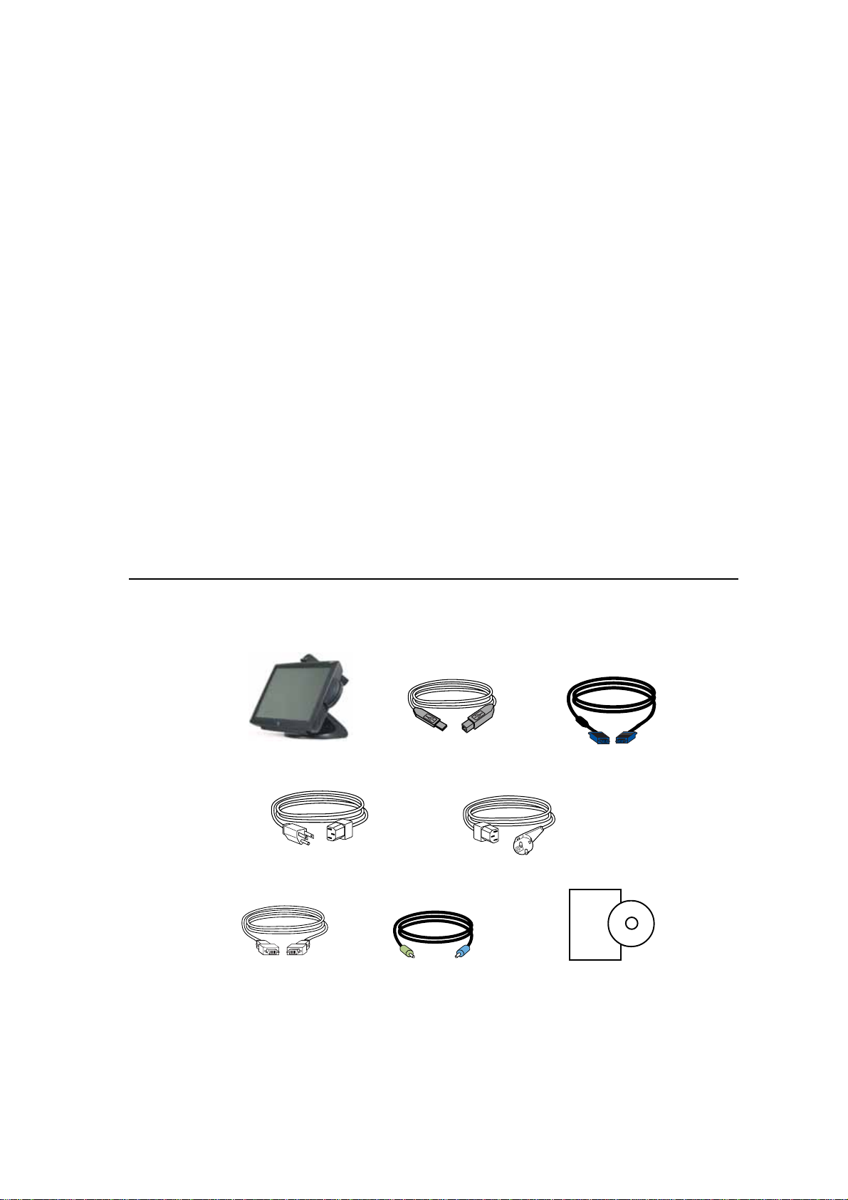
Check that the following items are present and in good condition:
Touchmonitor USB Cable Video cable
Power cable US/Candian Europea n power cable
DVI cable Speaker CD and Quick Install Guide
2-7
Page 13
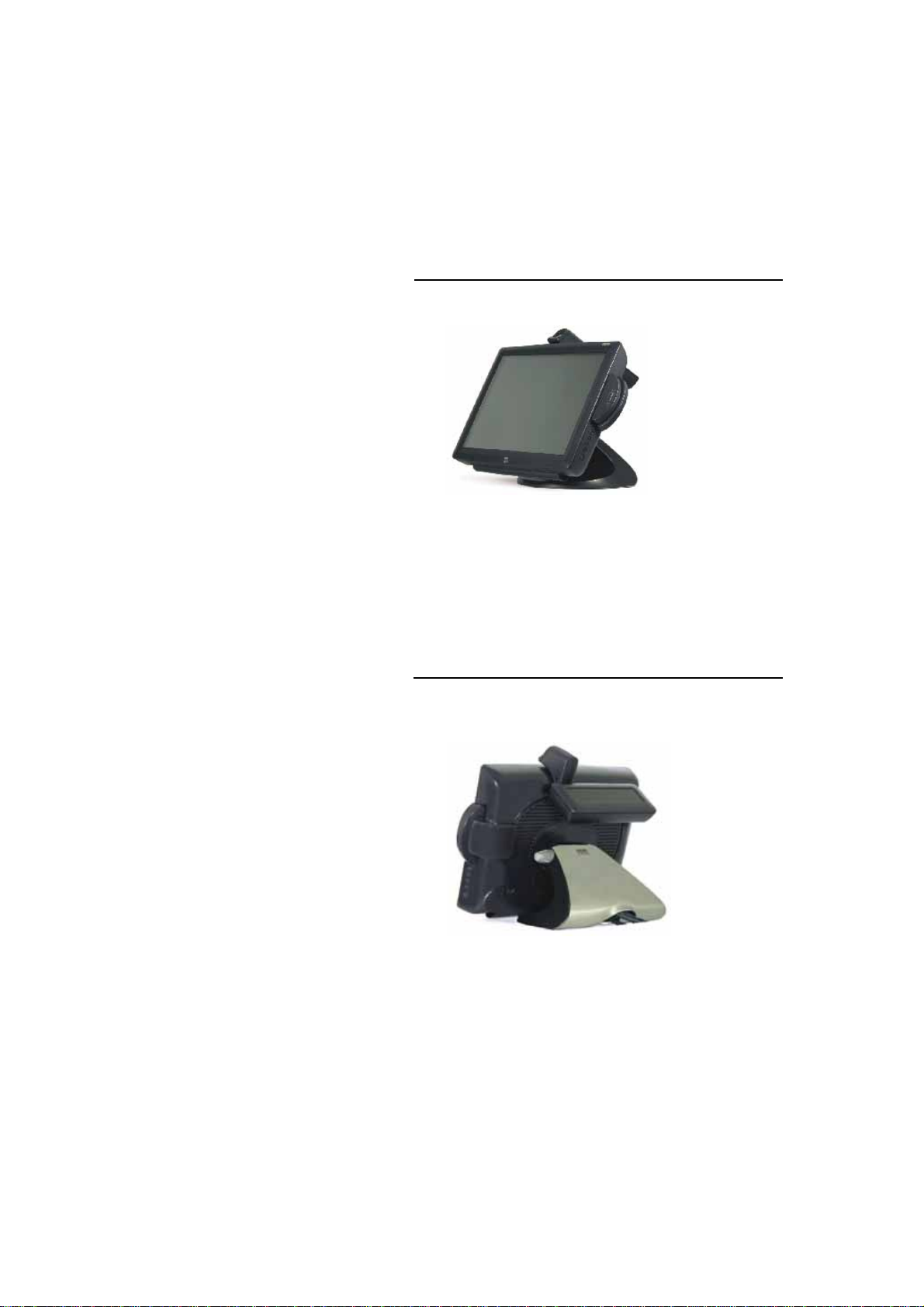
Product Overview
Main Unit
Note: Shown with optional Biometric & MSR.
Rear View
Note: Shown with optional Rear Facing Customer Display.
2-8 Elo Touchmonitor User Guide
Page 14
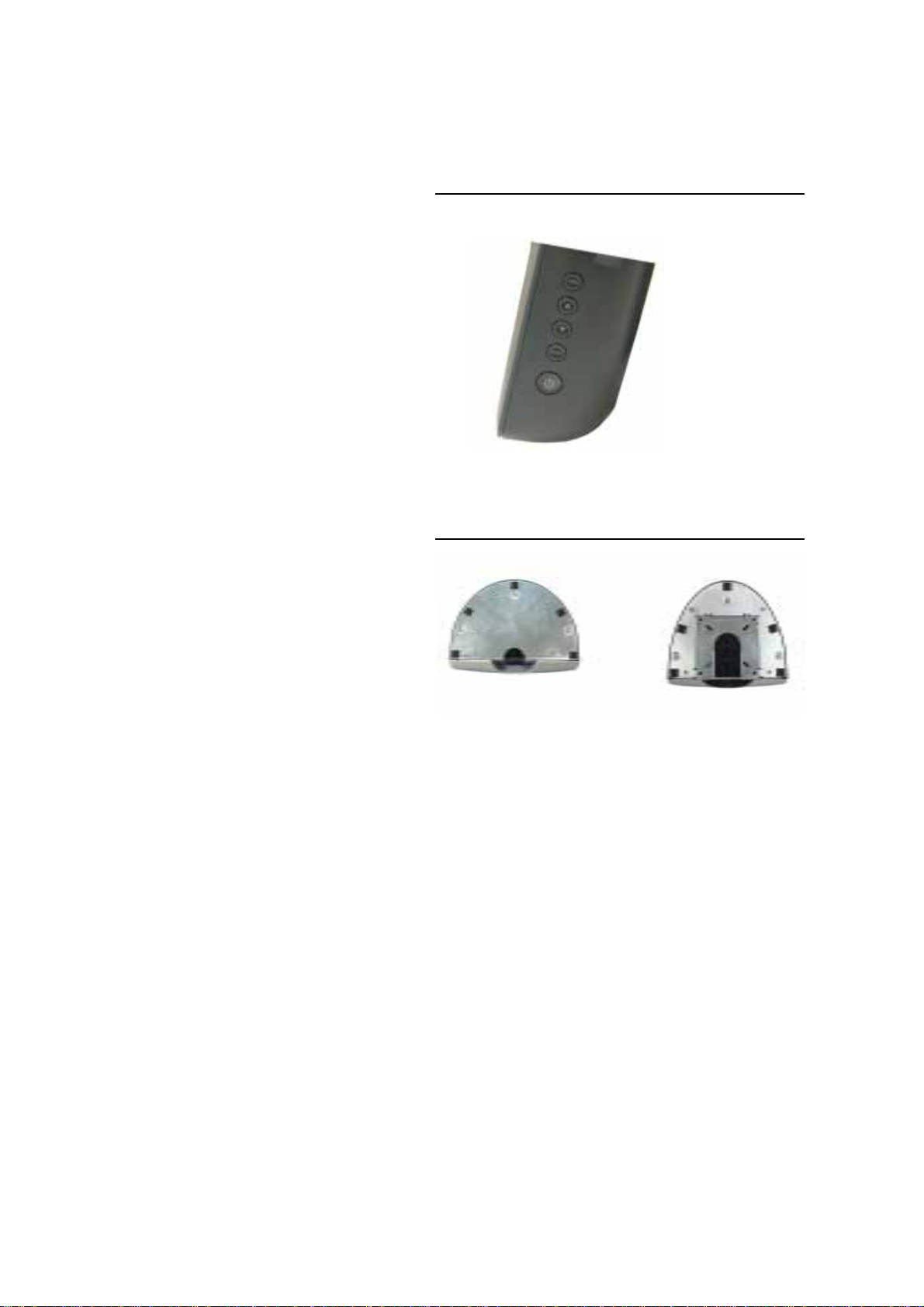
Side View
Base Bottom View
or
2-9
Page 15

KensingtonTM Lock
The Kensington
TM
lock is a security device that prevents theft. To
find out more about this security device, do to http://www.
kensington.com.
2-10 Elo Touchmonitor User Guide
Page 16

USB Interface Connection
Y our touchmonitor come s with only one touchscreen connector ca bles: USB ca ble. (For
Windows 2000, Me and XP systems only.)
To set up the display, please refer to the following figures a nd procedures:
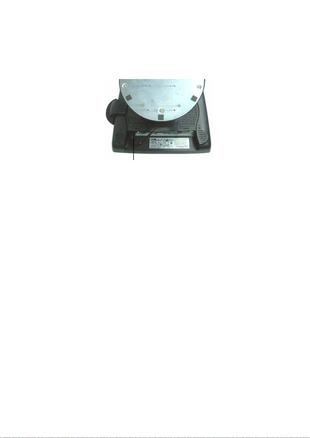
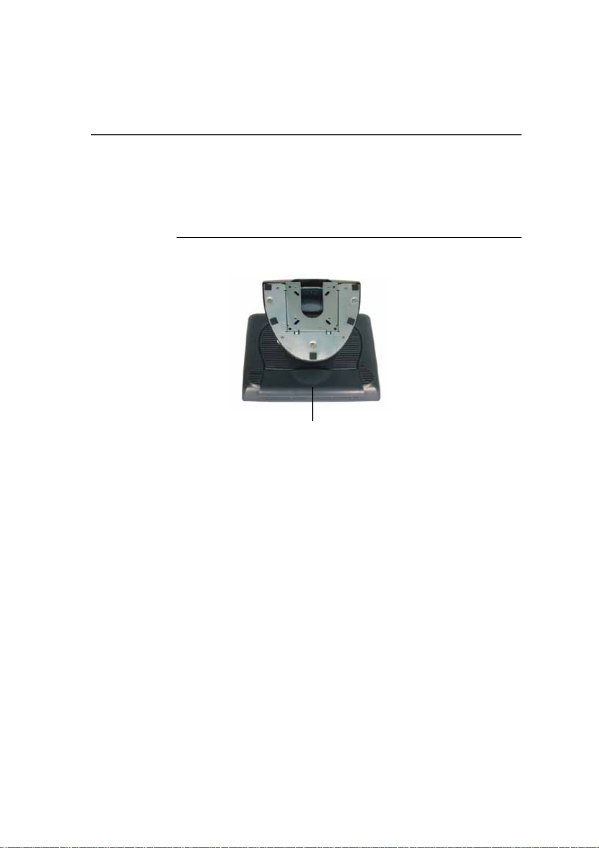
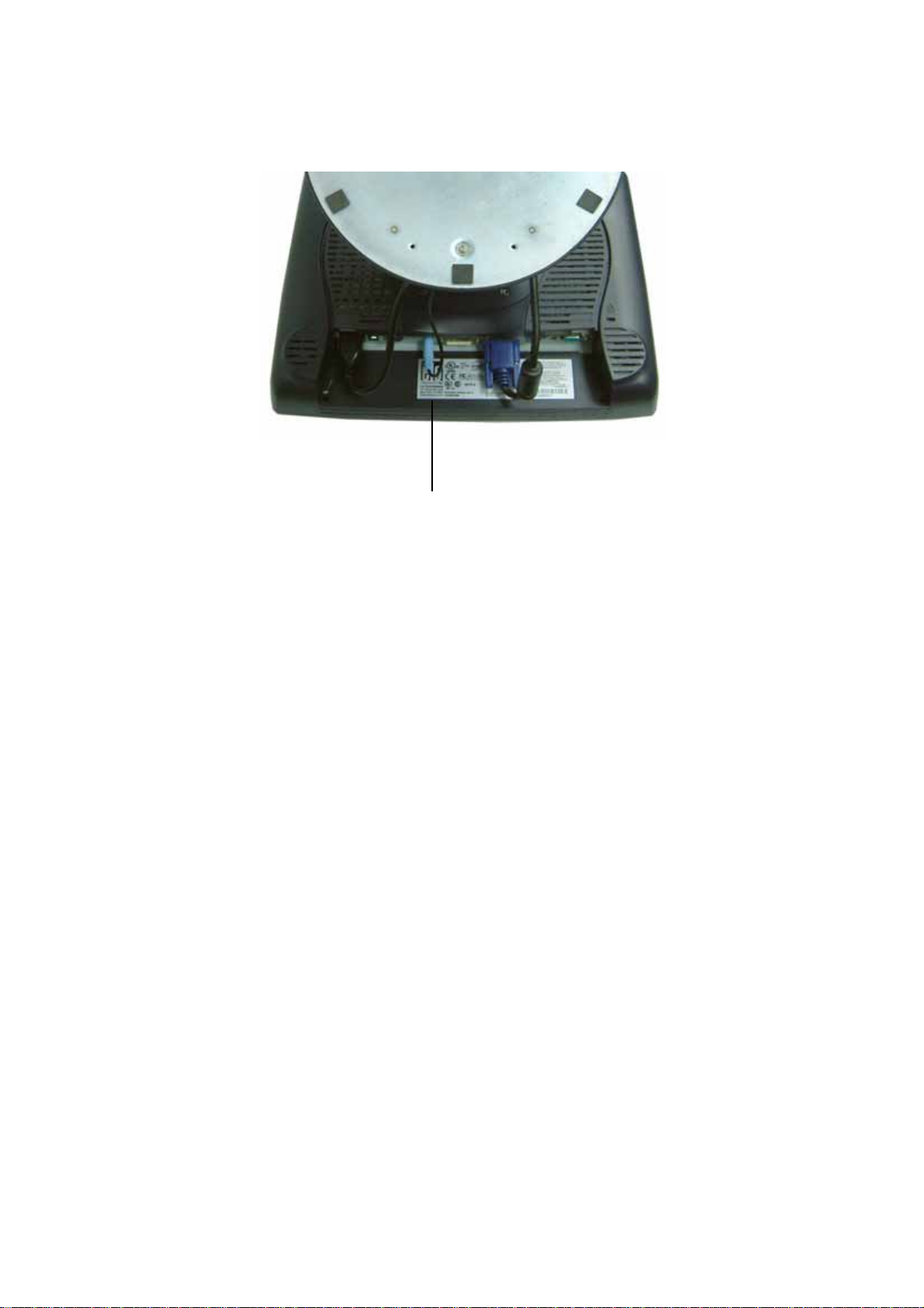
Remove the Cable Cover
The cables are connected at the back of the monitor.
cable cover
T o remove the cover, grasp the lip of the cover and pull towards you until it snaps off.
2-11
Page 17

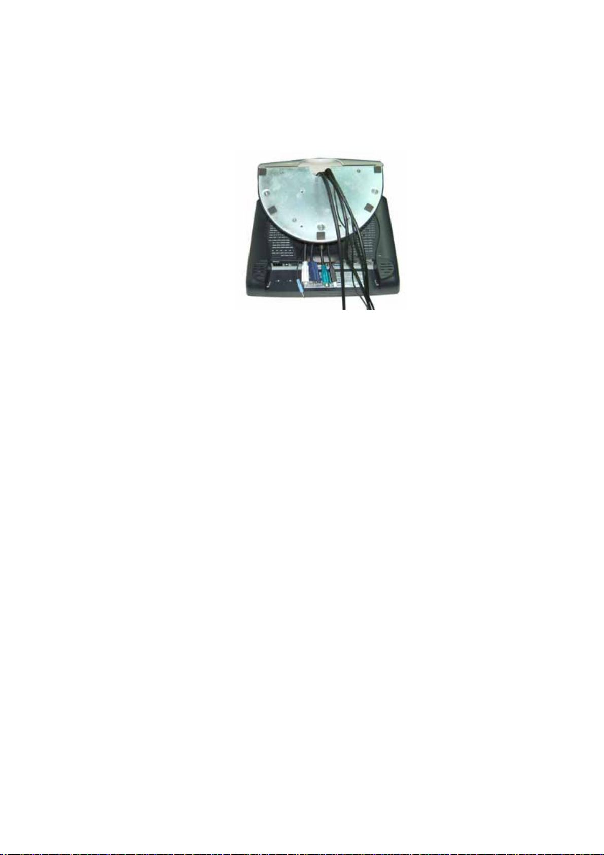
CAUTION Before connecting the cables to your touchmonitor and PC, be sure that the
computer and touchmonitor are turned off.
NOTE Before connecting the cables to the touchmonitor, route all the cables through
the hole in the second as shown in the picture above.
2-12 Elo Touchmonitor User Guide
Page 18
The following illustrations guide you step by step in connecting your touchmonitor
using a USB cable connection.
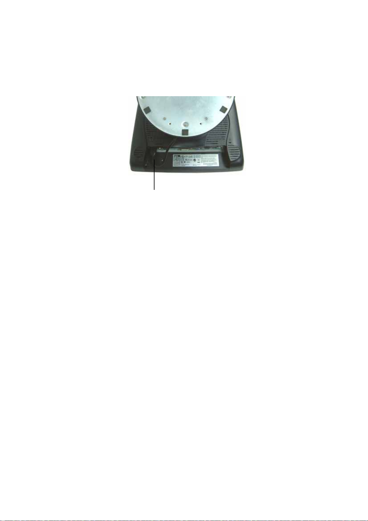
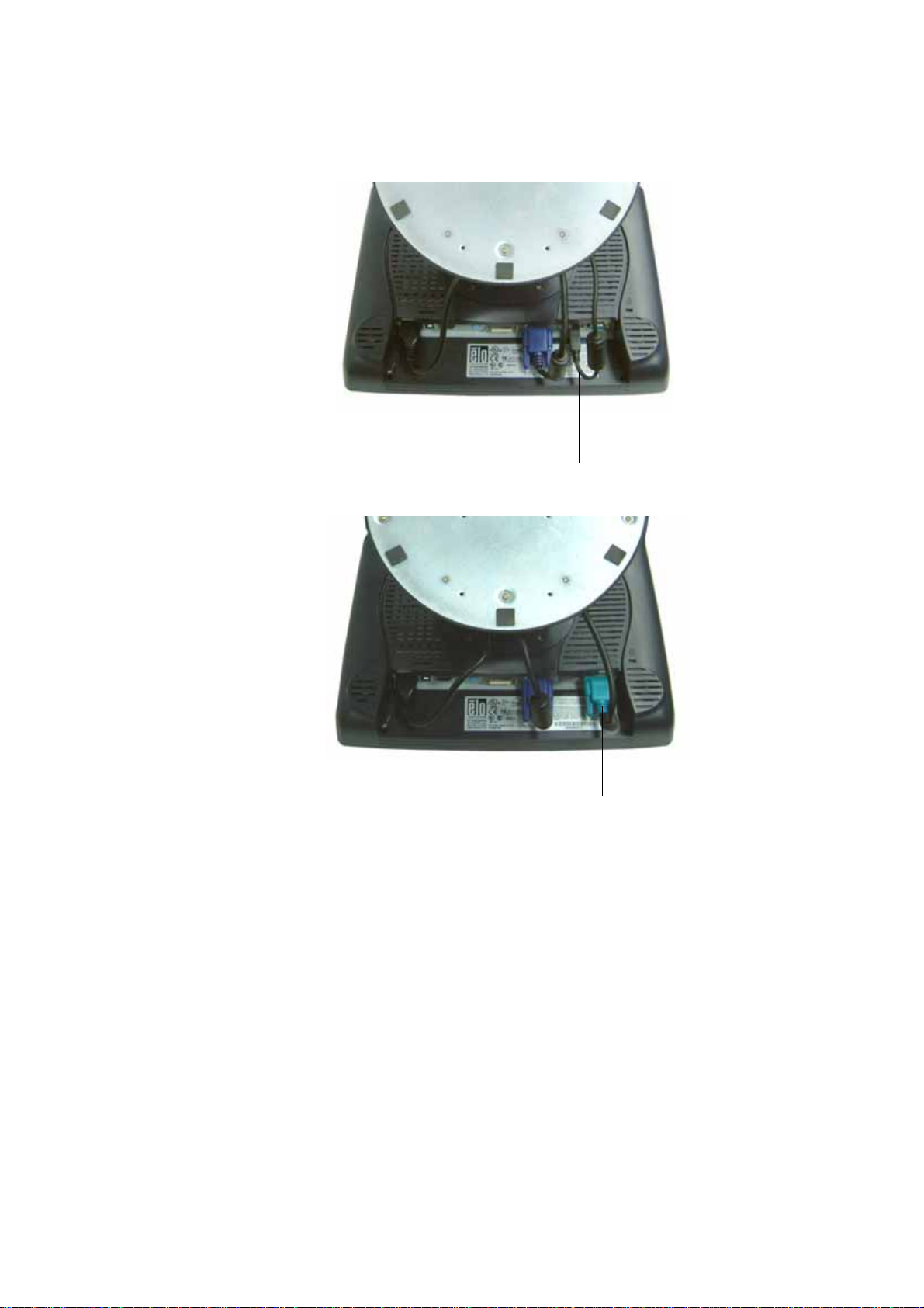
Power cord
Connect one end of the power cord to the monitor and the other end to wall.
Connect the power cable to the power port in the monitor.
2-13
Page 19
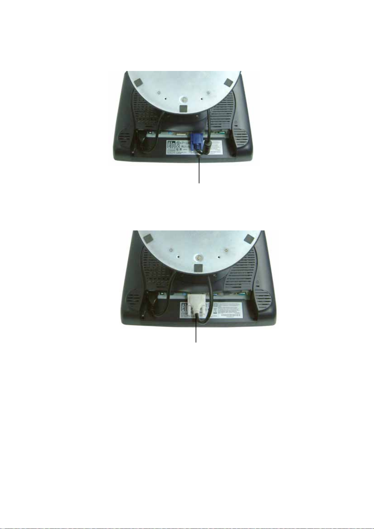
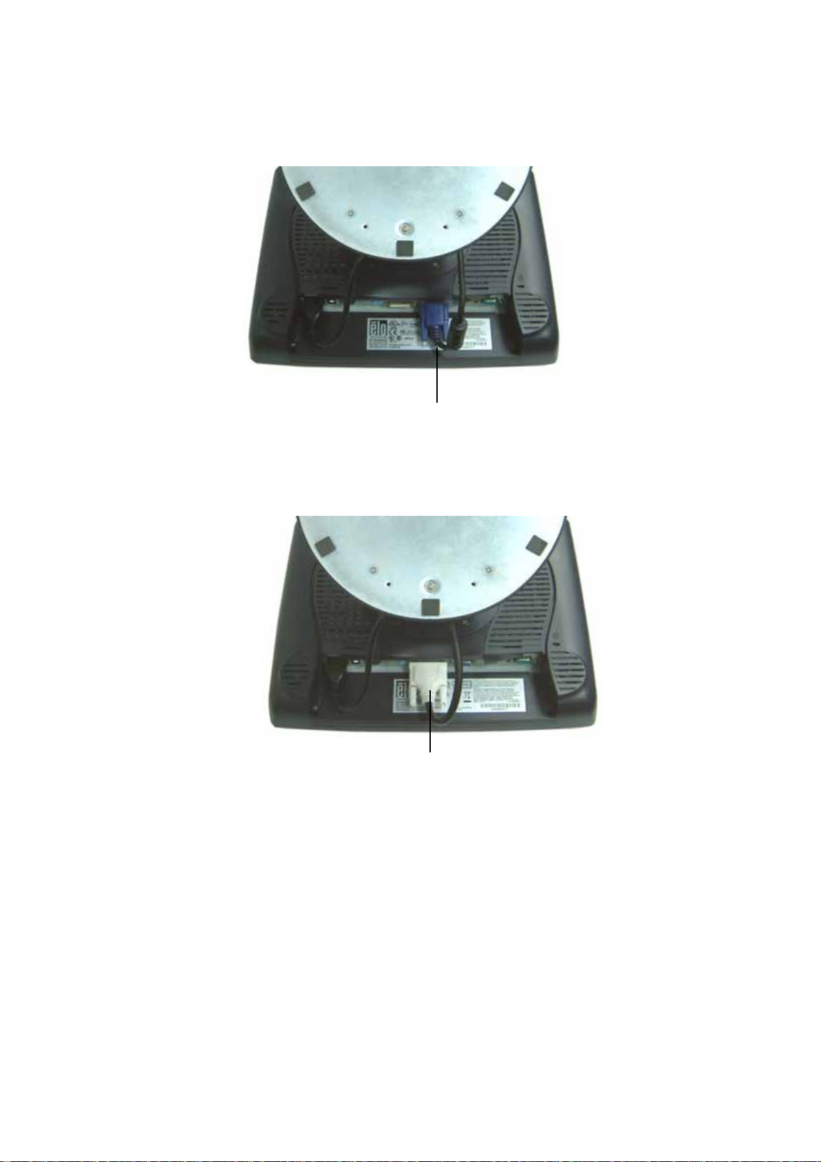
Video cable
Connect one end of the video cable to the rear side of computer and the other to the
LCD. T ighten by turning the two thumb screws clockwise to ensure proper grounding.
You ca n select DVI video cable or D-SUB15 video cable.
DVI cable
2-14 Elo Touchmonitor User Guide
Page 20
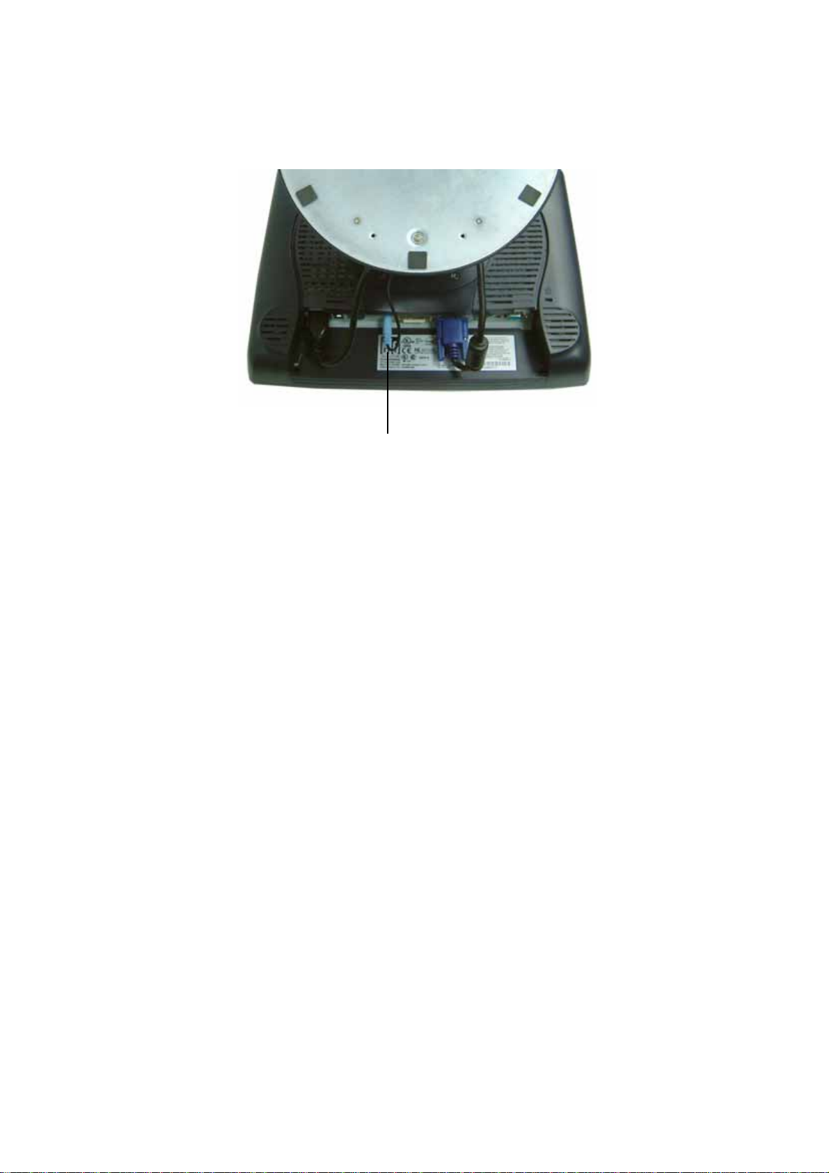
Speaker cable
Connect one end of the speaker cable to the speaker port in the computer and the other
end to the port in the monitor.
2-15
Page 21
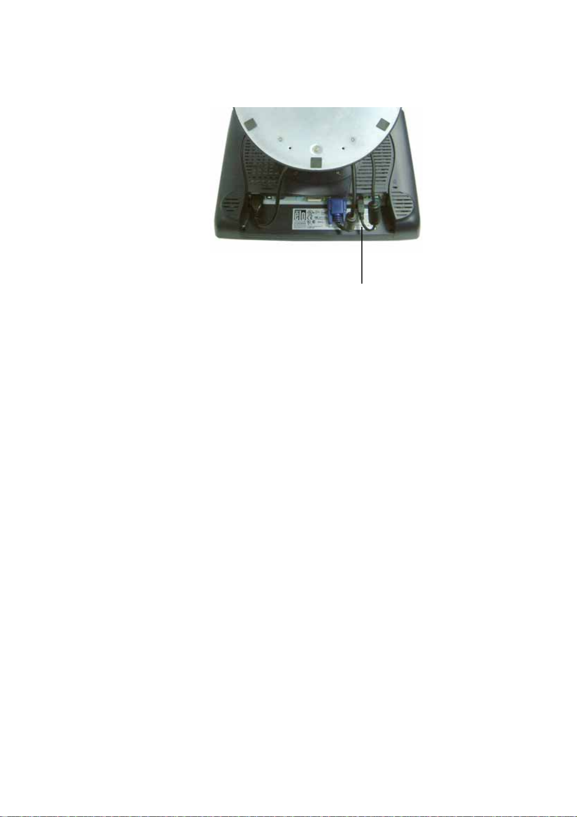
USB cable
Connect one end of the USB cable to the rear side of the computer and the other to the
LCD monitor.
The USB cable is for optional touch, MSR, CD and Finger Print Rea der. Only one USB
cable is needed because the device contains a self powered USB 1.1 Hub. Two self
powered ports are available for running other USB devices. For touch only, no USB
Hub is present.
2-16 Elo Touchmonitor User Guide
Page 22
USB / SERIAL Interface Connection
Y our touchmonitor come s with only one touchscreen connector ca bles: USB ca ble. (For
Windows 2000, Me and XP systems only.)
To set up the display, please refer to the following figures a nd procedures:
Remove the Cable Cover
The cables are connected at the back of the monitor.
cable cover
T o remove the cover, grasp the lip of the cover and pull towards you until it snaps off.
2-17
Page 23
CAUTION Before connecting the cables to your touchmonitor and PC, be sure that the
computer and touchmonitor are turned off.
NOTE Before connecting the cables to the touchmonitor, route all the cables through
the hole in the second as shown in the picture above.
2-18 Elo Touchmonitor User Guide
Page 24
The following illustrations guide you step by step in connecting your touchmonitor
using a USB cable connection.
Power cord
Connect one end of the power cord to the monitor and the other end to wall.
Connect the power cable to the power port in the monitor.
2-19
Page 25
Video cable
Connect one end of the video cable to the rear side of computer and the other to the
LCD. T ighten by turning the two thumb screws clockwise to ensure proper grounding.
You ca n select DVI video cable or D-SUB15 video cable.
DVI cable
2-20 Elo Touchmonitor User Guide
Page 26
Speaker cable
Connect one end of the speaker cable to the speaker port in the computer and the other
end to the port in the monitor.
2-21
Page 27
USB cable
Serial cable
For USB interface, connect one end of the USB cable to the rear side of the computer
and the other to the LCD monitor.
For Serial interfa ce, connect one end of the RS-232 ca ble to the rear side of the conputer
and the other to the LCD monitor.
2-22 Elo Touchmonitor User Guide
Page 28
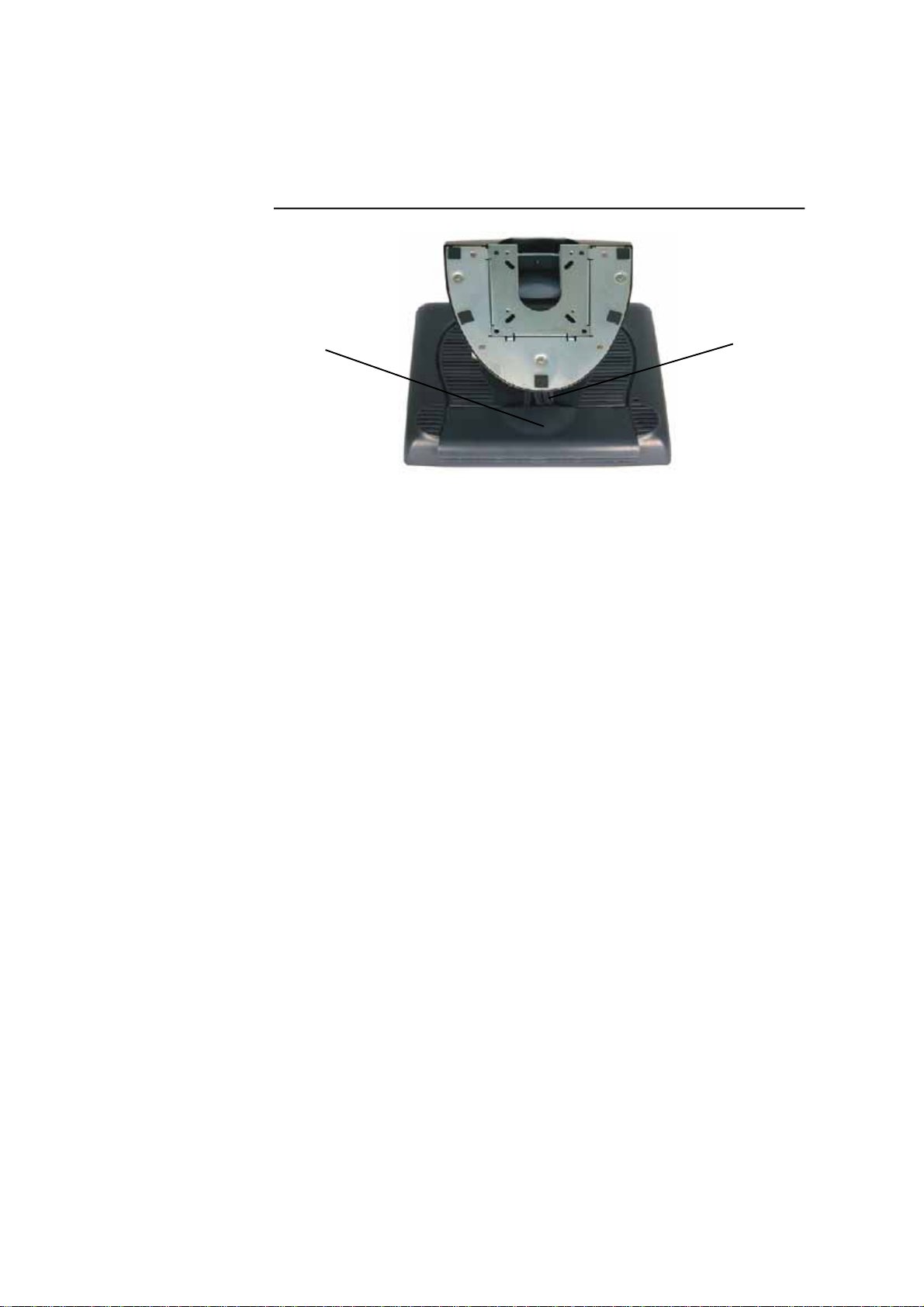
Replace the Cable Cover
Cable cover lip cables
Then you have attached all the ca bles to the monitor, gently bring all the ca ble s toward
the sta ndard so they fit under the cover lip.
Snap the Ca ble cover in place over the connections.
2-23
Page 29
Optimizing the LCD Display
To ensure the LCD display works well with your computer, configure the display mode
of your graphic card to make it less than or equal to 1024 x 768 resolution, and make
sure the timing of the display mode is compatible with the LCD display. Refer to Appendix A for more information about resolution. Compatible video modes for your
touchmonitor are listed in Appendix C.
Installing the Peripheral Device Drivers
Finger Print Reader
NOTE: This driver is for MS Windows 9x through XP.
1 On the TouchTools CD, browse to Touch Monitor Peripherals\Finger
Print Readers\Fingerprint Reader 229L 1529L\Driver Install\Drivers.
2 Double-click setup.exe
Follow the Install Shield Wizard procedure to complete the installation.
For a detailed software development kit, browse to Touch Monitor
Peripherals\Finger Print Readers\Fingerprint Reader 229L 1529L\Driver
Install\Drivers and open the following files:
• FDxSDKforWindows1 .20.zi p
• SecuBSPSDK for Windows2 .10.zip
You will enter one of the following serial numbers depending on your operating syste m:
• FDx SDK for Windows: 31-100s101-3586383
• FDx SDK for Windows CE: 32-100s101-9713291
• SecuBSP SDK for Windows: 41-100s101-7685871
• SecuBSP SDK for Windows CE: 42-100s101-1155462
• SecuBSP SDK: 51-100s101-5963137
Once the driver setup is complete, the demo program can be run from Touch Monitor
Peripherals\Finger Print Readers\Fingerprint Reader 229L 1529L\Demo\
BSPDemo.exe
2-24 Elo Touchmonitor User Guide
Page 30
Magnetic Stripe Reader
No device are needed.
Testing the USB MSR Keyboard Emulation
1 Plug in the device.
2 Open MS Word.
3 Slide the card through the MSR to view the data.
Testing the USB-HID Class MSR
1 On the CD, browse to Touch Monitor Peri pherals\Magnetic Stripe Card
Readers\Demo.
2 Open the Readme.txt and follow instructions to test the unit.
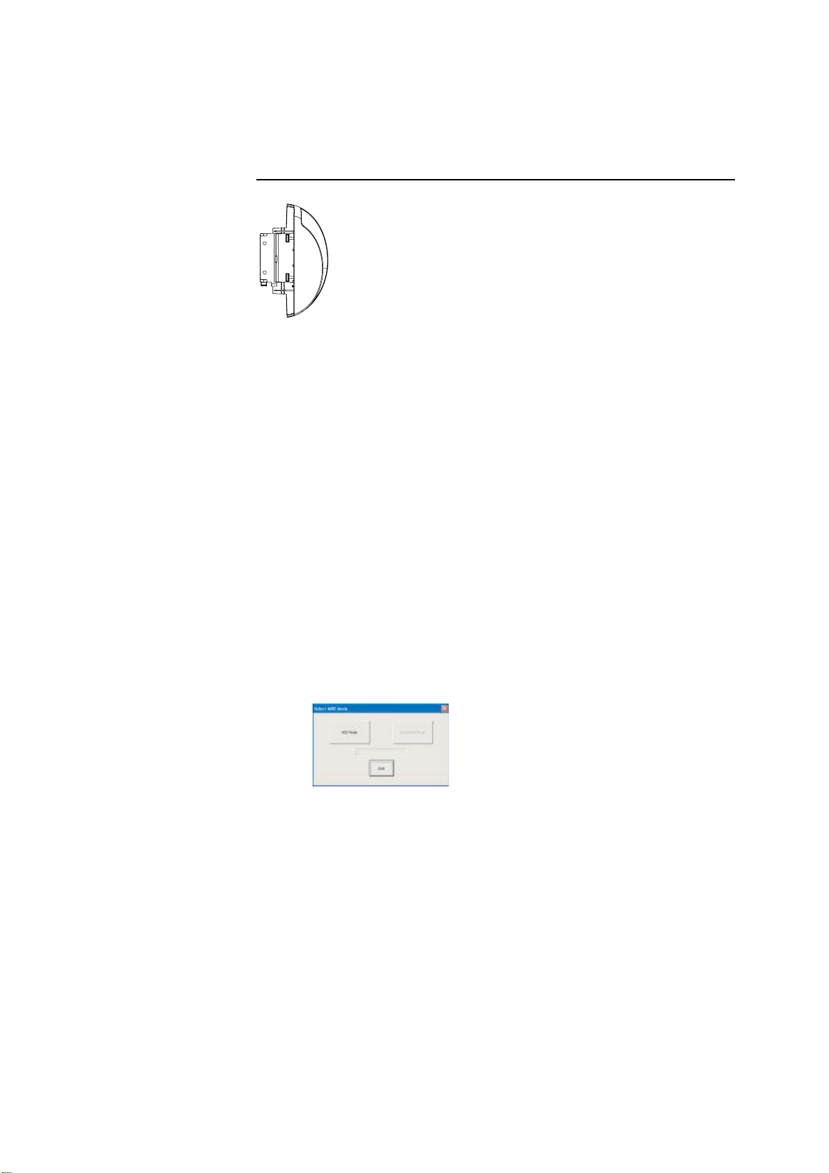
Convert MSR from HID to keyboard Emulation
1 To convert from HID mode to Keyboard Emulation mode
1.1 Double-click on the “MSR Cha nge Mode” icon on the desktop.
The following will appear:
1.2 The dim box will indicate the current setting. Click the “Keyboard Mode”
to switch to Keyboard Emulation mode.
1.3 Click “Quit” to close the window.
2 Open NotedPad.
3 Slide the card through the MSR to view the data.
2-25
Page 31

Convert MSR from keyboard emulation to HID
1 T o convert from Keyboard Emulation mode to HID mode
1.1 Double-click on the “MSR Cha nge Mode” icon on the desktop.
The following will appear:
1.2 The dim box will indicate the current setting. Click the “HID Mode” to
switch to HID mode.
1.3 Click “Quit” to close the window.
Rear Facing Customer Display
1. Insert your Elo TouchTools CD.
2. On the CD, browse to Touch Monitor Peripherals\Rear Fa cing Customer
Display\Drivers\USB Drivers. Click on the folder that has the name of your
operating system for the necessary drivers.
3. Once in this folder, open up the zi p file and open the install text file for further driver
installation instructions.
* Note: If your software requires OPOS Drivers, it is available in the following location:
Touch Monitor Peripherals\Rear Fa cing Customer Display\Drivers\OPOS Drivers.
T est Applications:
1. Insert your Elo TouchTools CD.
2. On the CD, browse to Touch Monitor Peripherals\Rear Fa cing Customer
Display\Testing\USB.
3. Open up the text file named USB Test and follow the instructions. This te sting
procedure assumes you have already installed the necessary USB drivers.
2-26 Elo Touchmonitor User Guide
Page 32

Barcode Scanner
1. Insert your Elo TouchTools CD.
2. On the CD, browse to Touch Monitor Peri pherals\Barcode Sca nner Startup\Drivers.
3. Double-click on USB7210.msi a nd follow the prompts given by the setup file.
4. Once you have finished installing the above: Right click on My Computer and
click on Properties. Click on the Hardware tab and then click Device Manager.
5. Double click on USB7210 Converter Module, which should be located in the
Other Devices section. Next click on Reinstall Driver.
6. Now your W indows operating system should guide you through the rest of the
installation process. If a ny files are requested, plea se provide the f ollowing pathna me
in your Elo TouchTools CD: Touch Monitor Peripherals\Barcode Scanner
Startup\Drivers.
T est Applications:
1. Insert your Elo TouchTools CD.
2. On the CD, browse to Touch Monitor Peri pherals\Barcode Scanner Startup\Te st
Applications.
3. Double click on Scanner Test Application Readme. This document will explain
how to test your scanner for basic functionality.
Your scanner default settings do not enable 2-D barcode reading ability. In order to
enable this option, follow the se steps:
1) Scan the barcodes below to enable PDF417 and MicroPDF417. These are
both types of 2-D barcodes.
2-27
Page 33

2) Now scan the barcode below to change your scanning pattern. Using this
sca nning pattern will allow you to read 2-D barcodes (you can still read 1-D
barcodes also).
The sca nner module also adds a Hall Effect Switch (HE Switch) that enables the unit to
automatically set the Trigger mode of the Scan Engine depending on the location of an
external magnet (included in scanner cradle).
The output of the HE Switch switches low (turns ON) when a magnetic field (south
polarity) perpendicular to the Hall sensor exceeds the operate point threshold, B
(typically 100 G magnetic field). When the magnetic field is reduced below the release
point, BRP, (typically 45 G magnetic field) the HE Switch output goes high (turns OFF).
The Hall Effect Switch goes to the USB Controller’s DSR input. As the HE Switch
opens or closes, it causes the USB Controller to initiate a USB Interrupt message to the
host. When the Host Application software detects the DSR input active LOW via the
USB Interrupt a nd a CDC me ssage (HE Switch is ON), it sends a ‘Continuous Trigger’
SSI comma nd to the Symbol Scan Engine.
The Sca n Engine turns on the laser a nd is a ble to scan and decode barcodes continuously
without the user having to press the trigger (momentary switch). When the Host Application software detects the DSR input HIGH (HE Switch is OFF), it sends a ‘Level
Trigger’ SSI command to the Symbol Scan Engine. The Sca n Engine turns off the laser
a nd will scan and decode barcodes only when the trigger is activated.
OP
2-28 Elo Touchmonitor User Guide
Page 34

Installing the Touch Driver Software
Elo T ouchSyste ms provides driver software that allows your touchmonitor to work with
your computer. Drivers are located on the enclosed CD-ROM for the following operating systems:
• Windows XP
• Windows 2000
• Windows Me
• Windows 98
• Windows 95
• Windows NT 4.0
• CE 2.x, 3.0, 4x
• Windows XP Embedded
• Windows 3.x
• MS DOS
• OS/2
Additional drivers and driver information for other operating systems (including
Macintosh and Linux) are available on the Elo T ouchSystems web site at www.elotouch.
com.
Y our Elo USB touchmonitor is plug-and-play complia nt. Inf ormation on the video ca pabilities of your touchmonitor is sent to your video display adapter when W indows starts.
If Windows detects your touchmonitor, follow the instructions on the screen to install a
generic plug-and-play monitor.
Refer to the appropri ate following section for driver installation instructions.
2-29
Page 35

Installing the USB Touch Driver
Installing the USB Touch Driver for Windows XP, Windows 2000,
Me and 98
1 Insert the Elo CD-ROM in your computer’s CD-ROM drive.
If Windows XP, Windows 2000,Windows 98, or Windows Me starts the Add New
Hardware Wizard:
2 Choose Next. Select “Search for the best driver for your device (Recommended)” a nd
choose Next.
3 When a list of search locations is displayed, place a checkmark on “Specify a
location” and use Browse to select the \EloUSB directory on the Elo CD-ROM.
4 Choose Next. Once the Elo TouchSyste ms USB touchscreen driver ha s been detected,
choose Next again.
5 You will see several files being copied. Insert your Windows 98 CD if prompted.
Choose Finish.
If Windows XP, Windows 2000,Windows 98, or Windows Me does not start the Add
New Hardware Wizard:
NOTE: For Windows XP and Windows 2000 you must have administrator access
rights to install the driver.
1 Insert the Elo CD-ROM in your computer’s CD-ROM drive. If the AutoStart feature
for your CD-ROM drive is a ctive, the syste m automatically detects the CD a nd starts
the setup program.
2 Follow the directions on the screen to complete the driver setup for your
version of Windows. If the AutoStart feature is not active:
1 Click Start > Run.
2 Click the Browse button to locate the EloCd.exe program on the CD-ROM.
3 Click Open, then OK to run EloCd.exe.
4 Follow the directions on the screen to complete the driver setup for your
version of Windows.
2-30 Elo Touchmonitor User Guide
Page 36

About Touchmonitor Adjustments
Your touchmonitor will unlikely require adjustment. Variations in video output and application may require adjustments to your touchmonitor to optimize the quality of the
display.
For best performance, your touchmonitor should be operating in native resolution, that
is 1024 x 768 at 60-75 Hz. Use the Display control panel in Windows to choose 1024 x
768 resolution.
Operating in other resolutions will degrade video perf ormance. For further information,
please refer to Appendix A.
All adjustments you make to the controls are automatically memorized. This feature
saves you from having to reset your choices every time you unplug or power your
touchmonitor off and on. If there is a power failure your touchmonitor settings will not
default to the factory specifications.
To restore factory set up, choose it from the OSD. See page 3-43.
C H A P T E R
3
OPERATION
3-31
Page 37

15” LCD Function Key
5
4
3
2
1
Controls Function
1 Power Switch Turns the display system power on or off.
2 Select Displays the OSD menus on the screen and used to
select (“Clockwise” a nd “Counter-clockwise” direction) the OSD control options
on the screen.
3 Adjusts the decreasing value of the selected
OSD control option.
4 Adjusts the increasing value of the selected OSD control option.
5 Menu Menu display and menu exit.
3-32 Elo Touchmonitor User Guide
Page 38

Controls and Adjustment
OSD Lock/Unlock
You are able to lock and unlock the OSD feature. The monitor is shi pped in the unlocked
position.
T o lock the OSD:
1 Press the Menu button a nd button simultaneously for 2 seconds. A window will
appear displaying “OSD Unlock”. Continue to hold the buttons down for another 2
seconds a nd the window toggles to “OSD Lock”.
Power Lock/Unlock
You are able to lock/unlock the Power feature. The monitor is shipped in the
unlockedposition.T o lock the power:
1 Press the Menu button a nd the si multaneously for 2 seconds. A window f or another
2 seconds and the window toggles to —Power Lock“.
OSD Menu Functions
T o display the OSD Menu press the Menu button.
1 Press the button or button to select the different OSD control option.
2 When the function you want to change is displayed, press the Select button.
T o adjust the Value of the function:
1 Pressing the button increases the value of the selected OSD control option.
2 Pressing the button decreases the value of the selected OSD control
option.
After adjusting the value s, the monitor will automatically save the changes.
NOTE: The OSD screen will disappear if no input activities are detected for 45 seconds.
3-33
Page 39

OSD Control Options
Brightness
• Background Luminance of the LCD panel is adjusted.
Contrast
• Adjusts the contrast or the values of color gain (RED, G REEN or BLUE).
Sharpness
• The sharpness can be adjustable.
Phase
• Adjusts the phase of the dot clock.
Auto Adjust
• Clock system auto a djustment (under 5 seconds).
OSD Left/Right
• The OSD screen is moved vertically right and left.
OSD Up/Down
• The OSD screen is moved vertically up and down.
Clock
• Adjusts the ratio of dividing frequency of the dot clock.
Color Temperature
• Sets R, G, B gain.
Current Input
• The frequency of the horizontal/vertical synchronizing signal under the input
indicated. (This information is under Auto Adjust icon)
OSD Position
• Allows the OSD indication position to be selected.
Language
• Select the language used f or the OSD menu from among English, France, Deutsch,
Spanish and Japanese.
Recall Defaults
• All data copy from factory shipment data.
OSD Timeout
• Adjust time for OSD to disappear.
Input Video Select
• Select D-SUB Analog, DVI Digital signal.
Volume
• To increase or decrease the sound level.
3-34 Elo Touchmonitor User Guide
Page 40

Power-Save (No Input)
• The LCD panel background is cut when there is no signal input (AC line power
consumption of 4w or less).
Power LED Display & Power Saving
General Power Saving Mode
When the power switch are switch on, this LED lights in green .
The LED indicates the different power status with altered LED colors when monitor
operates in different modes (see following table).
Power
Mode Consumption Indicator
On 50w max. Green
Sleep 4w max. Ora nge
Off 2w NO
W e recommend switching the monitor of f when it is not in use f or a long period of ti me.
Display Angle
For viewing clarity, you can tilt the LCD forward up 67 to 90 degrees.
3-35
Page 41

CAUTION In order to protect the LCD, be sure to hold the base when adjusting the LCD,
and take care not to touch the screen.
3-36 Elo Touchmonitor User Guide
Page 42

Controls and Adjustment
OSD Lock/Unlock
You are able to lock and unlock the OSD feature. The monitor is shi pped in the unlocked
position.
T o lock the OSD:
1 Press the Menu button a nd button simultaneously for 2 seconds. A window will
appear displaying “OSD Unlock”. Continue to hold the buttons down for another 2
seconds a nd the window toggles to “OSD Lock”.
Power Lock/Unlock
You are able to lock/unlock the Power feature. The monitor is shipped in the
unlockedposition.T o lock the power:
1 Press the Menu button a nd the si multaneously for 2 seconds. A window for another
2 seconds and the window toggles to —Power Lock“.
OSD Menu Functions
T o display the OSD Menu press the Menu button.
1 Press the button or button to select the different OSD control option.
2 When the function you want to change is displayed, press the Select button.
T o adjust the Value of the function:
1 Pressing the button increases the value of the selected OSD control option.
2 Pressing the button decreases the value of the selected OSD control
option.
After adjusting the value s, the monitor will automatically save the changes.
NOTE: The OSD screen will disappear if no input activities are detected for 45 seconds.
3-37
Page 43

OSD Control Options
Brightness
• Background Luminance of the LCD panel is adjusted
Contrast
• Gain of R, G, and B signal is adjusted.
Sharpness
• The sharpness can be adjustable.
Phase
• The phase of the dot clock is adjusted.
Auto Adjust
• Automatically adjusts the systems dot clock(takes approximately 5 seconds).
OSD Left/Right
• The osd screen is moved horizontally left and right.
OSD Up/Down
• The OSD screen is moved vertically up and down.
Clock
• The ratio of dividing frequency of the dot clock is adjusted.
Color Temperature
• Sets the R, G, and B gains.
Current Input
• The frequency of the horizontal/vertical synchronizing signal under the input is
indicated.(These information is under auto Adjust icon)
OSD Position
• The osd indication position can be selected.
Language
• Select the language for the OSD menu from among English, France, Deutsch,
Spanish and Japanese.
3-38 Elo Touchmonitor User Guide
Page 44

Recall Defaults
• Restore all original factory defaults.
OSD Timeout
• Adjust how long the OSD menu is displayed.
Input Video Select
• Select D-SUB Analog, dvi Digital signal.
Volume
• To increase or decrease the sound level.
3-39
Page 45

3-40 Elo Touchmonitor User Guide
Page 46

C H A P T E R
4
TROUBLESHOOTING
If you are experiencing trouble with your touchmonitor, refer to the following table. If
the problem persists, please contact your local dealer or our service center. Elo Technical Support numbers are listed on the last page of this manual.
Solutions to Common Problems
Problem Suggestion(s)
The monitor does not respond after Check that the monitor’s Power Switch is on.
you turn on the system.
Turn off the power and check the monitor’s power cord and signal
cable for proper connection.
Characters on the screen are dim Refer to the Controls and Adjustments section to adjust the brightness.
The screen is blank During operation, the monitor screen may automatically turn off as a
result of the Power Saving feature. Press any key to see if the screen
reappears.
Refer to the Controls and Adjustments section to adjust the brightness.
OSD or power buttons don’t work Check to see that they are not locked out. See page 3-33.
“Out of Range” display check to see of the resolution or vertical frequency of your computer is
higher than that of the LCD display.
Reconfigure the resolution of your computer to make it less than or
equal to 1024x768. 1024x768 is optimal. See Appendix A for more
information on resolution.
Touch doesn’t work Make sure cable is securely attached at both ends.
4-41
Page 47

4-42 Elo Touchmonitor User Guide
Page 48

C H A P T E R
A
NATIVE RESOLUTION
The native resolution of a monitor is the resolution level at which the LCD panel is
designed to perform best. For the Elo LCD touchmonitor, the native resolution is 1024
x 768 for the 15.0 inch size. In almost all cases, screen i mages look best when viewed at
their native resolution. You can lower the resolution setting of a monitor but not increa se
it.
Input Video 15.0" LCD
640 x 480 (VGA) Transforms input format to 1024 x 768
800 x 600 (SVGA) Transforms input format to 1024 x 768
1024 x 768(XGA) Display in Native Resolution
The native resolution of an LCD is the a ctual number of pixels horizontally in the LCD
by the number of pixels vertically in the LCD. LCD resolution is usually repre sented by
the following symbols:
VGA 640 x 480
SVGA 800 x 600
XGA 1024 x 768
A-43
Page 49

As an example, a SVGA resolution LCD panel has 800 pixels horizontally by 600 pixels
vertically. Input video is also represented by the same terms. XGA input video has a
format of 1024 pixels horizontally by 768 pixels vertically. When the input pixels contained in the video input format match the native resolution of the pa nel, there is a one to
one correspondence of mapping of input video pixels to LCD pixels. As an example, the
pixel in column 45 and row 26 of the input video is in column 45 and row 26 of the
LCD. For the case when the input video is at a lower or higher resolution than the native
resolution of the LCD, the direct correspondence between the video pixels a nd the LCD
pixels is lost. The LCD controller can compute the correspondence between video pixels and LCD pixels using algorithms contained on its controller. The accuracy of the
algorithms determines the fidelity of conversion of video pixels to LCD pixels. Poor
fidelity conversion can result in artifacts in the LCD displayed image such as varying
width characters.
A-44 Elo Touchmonitor User Guide
Page 50

C H A P T E R
B
TOUCHMONITOR SAFETY
This manual contains inf ormation that is i mportant for the proper setup and maintenance
of your touchmonitor. Before setting up and powering on your new touchmonitor, read
through this ma nual, e specially Chapter 2 (Installation), and Chapter 3 (Operation).
1 To reduce the risk of electric shock, follow all safety notices a nd never open the
touchmonitor case.
2 Turn off the product before cleaning
3 Your new touchmonitor is equipped with a 3-wire, grounding power cord. The power
cord plug will only fit into a grounded outlet. Do not atte mpt to fit the plug into an
outlet that has not been configured for this purpose. Do not use a damaged power
cord. Use only the power cord that comes with your Elo T ouchSyste ms Touchmonitor.
Use of an unauthorized power cord may invalidate your warranty.
4 The slots located on the sides a nd top of the touchmonitor ca se are f or ventilation. Do
not block or insert a nything inside the ventilation slots.
5 It is important that your touchmonitor remains dry. Do not pour liquid into or onto
your touchmonitor. If your touchmonitor become s wet do not attempt to repair it
yourself.
B-45
Page 51

Care and Handling of Your Touchmonitor
The following tips will help keep your Elo Entuitive touchmonitor functioning at the
optimal level.
• To avoid risk of electric shock, do not disassemble the brick supply or display unit
cabinet. The unit is not user serviceable. Remember to unplug the display unit from
the power outlet before cleaning.
• Do not use alcohol (methyl, ethyl or isopropyl) or any strong dissolvent. Do not use
thinner or benzene, abrasive cleaners or compressed air.
• T o clean the display unit cabinet, use a cloth lightly dampened with a mild detergent.
• Avoid getting liquids inside your touchmonitor. If liquid does get inside, have a
qualified service technician check it before you power it on again.
• Do not wipe the screen with a cloth or sponge that could scratch the surface.
• To clea n the touchscreen, use window or gla ss cleaner. Put the clea ner on the rag and
wipe the touchscreen. Never a pply the cleaner directly on the touchscreen .
Warning
This product consists of devices that may contain mercury, which must be recycled or
disposed of in accordance with local, state, or federal laws. (Within this system, the
backlight lamps in the monitor display contain mercury.)
Waste Electrical and Electronic Equipment(WEEE) Directive
In the European Union, this label indicates that this product should not be disposes of
with household waste. It should be deposited at an appropriate facility to enable recovery a nd recycling.
B-46 Elo Touchmonitor User Guide
Page 52

TECHNICAL SPECIFICATIONS
Display Modes
Your Elo Entuitive touchmonitor is compatible with the following standard
video modes:
Item Resolution T ype H. Scan(KHz) V. Scan(Hz) Pol.
1 640X350 V G A 31.469 70.087 + /
2 720X400 VGA 31.469 70.087 - / +
3 640X480 V G A 31.469 59.940 - /
4 640X480 VESA72 37.861 72.809 -/
5 640X480 VESA75 37.500 75.000 -/
6 800X600 SVGA 35.156 56.250 +/+
7 800X600 SVGA 37.879 60.317 +/+
8 800X600 VESA72 48.077 72.188 +/+
9 800X600 VESA75 46.875 75.000 +/+
10 1024X768 XGA 48.363 60.004 -/11 1024X768 XGA 56.476 70.069 -/12 1024X768 VESA75 60.023 75.029 +/+
C H A P T E R
C
C-47
Page 53

Touchmonitor Specifications
Model 1529L
LCD Display 15.0” TFT Active Matrix Panel
Display Size 304.1(H) x 228(V) mm
Pixel Pitch 0.297(H) x 0.297(V) mm
Display Mode VGA 640 x 350 (70 Hz)
VGA 720 x 400 (70 Hz)
VGA 640 x 480 (60 / 72 / 75 Hz)
SVGA 800 x 600 (56 / 60 / 72 / 75Hz)
XGA 1024 x 768 (60 / 70 / 75Hz)
Native XGA 1024 x 768
Contrast Ratio 400 : 1 (typical)
Brightness 350 cd/m
SC 294 cd/m
LCD 350 cd/m2 (Typical)
AccuTouch 287 cd/m
IntelliTouch 322 cd/m
CarrollTouch 322 cd/m
Surface Capacitive 294 cd/m
Acoustic Pulse Recognition 322 cd/m
Response Ti me Tr= 5 msec, Tf= 11 mesc typical(CPT CLAA150XP01P)
Tr= 4 msec, Tf= 12 me sc typical(AU G150XG01)
Display Color 16.2 million color, 6 bit with dithering
Viewing Angle (L/R)= -60o/+60o (typical), (U/D) -60o/+40o (typical)
Input Signal VGA Analog Video R.G.B. Analog 0.7V peak to peak
Sync TTL Positive or Negative, Composite Sync, Sync on green
DVI Video Digital TMDS Input
Signal Connector 15 Pin D-Sub, D VI-D
Front Control Power on / off , Menu, , , Select
OSD Contrast, Brightness, H/V-Position, Recall default,
Color Te mperature, Volume, Sharpnss,
Phase, Clock OSD H/V position, OSD Time, Auto Adjust,
OSD Language, Input Select
Plug & Play DDC1 / 2B
Touch Panel (optional) AccuTouch, IntelliTouch and CarrollTouch, Surface Capacitive,
Acoustic Pulse Recognition
Power Input: AC 85-265V, 47-63Hz, or DC 12V/4A (max.)
Operating Conditions Temp 0oC ~ 40oC (41oF ~ 95oF)
Humidity 20% ~ 80% (No Condensation)
Altitude To 12,000 Feet
Dimensions (HxWxD) 354 x 301 x 285mm
Weight (Net) 20.1lbs., monitor weight 16.2 lbs.
Certifications UL, C-UL, FCC-B, CE, Semko, VCCI, MPRII, C-TICK
2
with AT 287 cd/m2, IT 322 cd/m2, IR 322 cd/m2,
2
2
(Typical)
2
(Typical)
2
(Typical)
2
(Typical)
2
(Typical)
C-48 Elo Touchmonitor User Guide
Page 54

AccuTouch Touchscreen Specifications
Mechanical
Construction Top: Polyester with outside hard-surface coating with clear or
antiglare finish.
Inside: Transparent conductive coating.
Bottom: Glass substrate with uniform resistive coating. Top and
bottom layers separated by Elo-patented separator dots.
Positional Accuracy Standard deviation of error is less than 0.080 in. (2.03 mm). This
equates to less than ±1%.
T ouchpoint Density More than 100,000 touchpoints/in² (15,500 touchpoints/cm²).
T ouch Activation Force Typically less than 4 ounces (113 grams).
Surface Dura bility Meets Taber Abrasion Test (ASTM D1044), CS-10F wheel, 500 g.
Meets pencil hardness 3H.
Expected Life AccuTouch technology has been operationally tested to greater than
Performance 35 million touches in one location without failure, using a stylus
similar to a finger.
Optical
Light Transmission Typically 85% at 550-nm wavelength (visible light spectrum).
(per ASTM D1003)
Visual Resolution All measurements made using USAF 1951 Resolution Chart, under
30 X magnification, with test unit located approximately 1.5 in.
(38 mm) from surface of resolution chart.
Antiglare surface: 6:1 minimum.
Haze (per ASTM D1003) Antiglare surface: Less than 15%.
Gloss (per ASTM D2457) Antiglare surface: 90 ± 20 gloss units tested on a hard-coated front
surface.
C-49
Page 55

IntelliTouch Touchscreen Specifications
Mechanical
Positional Accuracy Standard deviation of error is less than 0.080 in. (2.03 mm).
Equates to less than ±1%.
T ouchpoint Density More than 100,000 touchpoints/in2 (15,500 touchpoints/cm2).
T ouch Activation Force Typically less than 3 ounces (85 grams).
Surface Durability Surface durability is that of glass, Mohs’ hardness rating of 7.
Expected Life Performa nce No known wear-out mechanism, as there are no layers, coatings,
or moving parts. IntelliTouch technology has been operationally
tested to more than 50 million touches in one location without
failure, using a stylus similar to a finger.
Sealing Unit is sealed to protect against splashed liquids, dirt, and dust.
Optical
Light T ransmission (per ASTM 90%
D1003)
Visual Resolution All measurements made using USAF 1951 Resolution Chart,
under 30X magnification, with test unit located approximately
1.5 in (38 mm) from surface of resolution chart.
Clear surface: Excellent, with no noticeable degradation.
Antiglare surface: 6:1 minimum.
Gloss (per ASTM D2457
using a 60-degree gloss meter) Antiglare surface: Curved: 60 ± 20 gloss units or 75 ± 15 gloss
units.
Environmental
Chemical Resistance The active area of the touchscreen is resistant to all chemicals
that do not affect glass, such as:
Acetone
Toluene
Methyl ethyl ketone
Isopropyl alcohol
Methyl alcohol
Ethyl acetate
Ammonia-ba sed glass cleaners
Gasoline
Kerosene
Vinegar
Electrostatic Protection (per Meets Levels 4 (15kV air/8 kV contact discharge)
EN 61 000-4-2, 1995)
C-50 Elo Touchmonitor User Guide
Page 56

Infrared Touchscreen Specifications
Mechanical
Input Method Input Method Finger or gloved hand activation
Electrical
Positional Accuracy T ypical centroid accuracy: 2 mm with 1 mm STD error
Resolution Touchpoint density is based on controller resolution of 4096 x
4096
T ouch Activation Force No minimum touch activation force is required
Controller Board: Serial (RS232) or USB 1.1
Optical
Light Transmission Glass overlay: 90% per ASTM D1003-92
Environmental
Chemical Resistance Glass overlays: The touch active area of the touchscreen is
resistant to chemicals that do not affect glass, such as: acetone,
toluene, methyl ethyl ketone, isopropyl alcohol, methyl alcohol,
ethyl acetate, ammonia-based glass cleaners, ga soline, kerosene,
vinegar. Polycarbonate bezel: around perimeter of display has
some sensitivity to hydrocarbons.
Durability
Surface Dura bility Glass filter option: Surface durability is that of glass, Mohs’
hardness rating of 7.
C-51
Page 57

Acoustic Pulse Recognition Specification
MECHANICAL
Input method Finger, finger nail, gloved hand, or stylus activation
ELECTRICAL
Position accuracy 1% max. error
Resolution accura cy Touchpoint density is based on controller resolution of 4096 x 4096
T ouch activation force Typically 2 to 3 ounces (55 to 85 grams)
Controller Board: USB 1.1
OPTICAL
Light transmission 90%+/-5%
ENVIRONMENTAL
Chemical resistance The touch activation area of the touchscreen is resistant to chemicals
that do not affect glass such as: acetone, toluene, methyl ethyl ketone,
isopropyl alcohol, methyl alcohol, ethyl acetate, ammonia-based glass
cleaners, gasoline, kerosene, vinegar
DURABILITY
Surface durability Surface durability is that of glass, Mohs’ hardness rating of 7
Expected life No known wear-out mecha nism, a s there are no layers, coatings, or moving
parts. APR technology has been operationally tested to more than 50
million touches in one location without failure, using a stylus similar
finger.
C-52 Elo Touchmonitor User Guide
Page 58

15” LCD Touchmonitor(ET1529L-XXXA-1-XX-G) Dimensions
15” LCD Touchmonitor(ET1529L-XXXA-1-XX-T-G) Dimensions
C-53
Page 59

C-54 Elo Touchmonitor User Guide
Page 60

REGULATORY INFORMATION
I. Electrical Safety Information:
A) Compliance is required with respect to the voltage, frequency, and current requirements indicated on the manufacturer’s label. Connection to a different power source
than those specified here in will likely re sult in i mproper operation, da mage to the equipment or pose a fire hazard if the limitations are not followed.
B) There are no operator serviceable parts inside this equipment. There are hazardous
voltages generated by this equipment which constitute a safety hazard. Service should
be provided only by a qualified service technician.
C) This equipment is provided with a deta cha ble power cord which ha s an integral safety
ground wire intended for connection to a grounded safety outlet.
1) Do not substitute the cord with other than the provided approved type. Under
no circumstances use an adapter plug to connect to a 2-wire outlet as this will
defeat the continuity of the grounding wire.
2) The equipment require s the use of the ground wire as a part of the safety
certification, modification or misuse ca n provide a shock hazard that can result
in serious injury or death.
3) Contact a qualified electrician or the manufa cturer if there are questions about
the installation prior to connecting the equipment to mains power.
II. Emissions and Immunity Information
A) Notice to Users in the United States: This equipment has been tested and found to
comply with the limits for a Class B digital device, pursuant to Part 15 of FCC Rules.
These limits are designed to provide rea sonable protection against harmful interference
in a residential installation. This equipment generates, uses, and can radiate radio frequency energy, and if not installed and used in accordance with the instructions, may
cause harmful interference to ra dio communications.
B) Notice to Users in Canada: This equipment complies with the Cla ss B limits for ra dio
noise emissions from digital apparatus a s e stablished by the Radio Interference Regulations of Industrie Canada.
C) Notice to Users in the European Union: Use only the provided power cords and
interconnecting cabling provided with the equipment. Substitution of provided cords
and cabling may compromise electrical safety or CE Mark Certification for emissions or
immunity a s required by the following standards:
55
Page 61

This Information Technology Equipment (ITE) is required to have a CE Mark on
the ma nufacturer’s label which means that the equipment ha s been tested to the
following Directives and Sta ndards:
This equipment has been te sted to the require ments for the CE Mark as required
by EMC Directive 89/336/EEC indicated in European Standard EN 55 022 Cla ss
B a nd the Low Voltage Directive 73/23/EEC as indicated in European Standard
EN 60 950.
D) General Information to all Users: This equipment generates, uses and can radiate
radio frequency ener gy. If not installed a nd used according to this ma nual the equi pment
may cause interference with radio and television communications. There is, however, no
guarantee that interference will not occur in any particular installation due to site-specific factors.
1) In order to meet emission and immunity requirements, the user must observe
the following:
a) Use only the provided I/O cables to connect this digital device with any
computer.
b) To ensure compliance, use only the provided ma nufacturer’s approved
line cord.
c) The user is cautioned that changes or modifications to the equipment
not expressly approved by the party re sponsible for compliance could
void the user’s authority to operate the equipment.
2) If this equipment a ppears to cause interference with radio or television reception, or
a ny other device:
a) Verify as a n emission source by turning the equipment off and on.
b) If you determine that this equipment is causing the interference, try to
correct the interference by using one or more of the following measures:
i) Move the digital device away from the affected receiver.
ii) Reposition (turn) the digital device with respect to the af f ected
receiver.
ii i) Reorient the affected receiver’s antenna.
iv) Plug the digital device into a different AC outlet so the digital
device and the receiver are on different branch circuits.
v) Disconnect and remove any I/O cables that the digital device
does not use. (Unterminated I/O cables are a potential source of
high RF emission levels.)
vi) Plug the digital device into only a grounded outlet receptacle.
Do not use AC adapter plugs. (Removing or cutting the line cord
ground may increase RF e mission levels and may also present a
lethal shock hazard to the user.)
If you need additional help, consult your dealer, manufacturer, or an experienced radio
or television technician.
56 Elo Touchmonitor User Guide
Page 62

B
L
U
I
C
P
E
A
R
A
R
A
G
N
I
E
T
N
"The application of this monitor is restricted to special controlled luminous environments.The screen surface trend to
reflect a nnoying light of lamps a nd sunlight. To avoid these reflections the monitor should not be positioned in front of a
window or directed to luminaries. The monitor is in compliance with Reflection Class III according to ISO
13406-2"
"Die Anwendung dieses Bildschirms ist auf speziel kontrollierte
Umgebungsbeleuchtungen eingeschränkt. Die Bildschirmoberfläche neigt zu störenden Spielungen von Lampen und
Sonnenlicht. Um diese Refelxionen zu vermeiden sollte der Monitor nicht auf Fenster und Beleuchtungseinrichtungen
ausgerichtet sein. Der Monitor erfüllt nur die Relexionsklasse III nach ISO 13406-2"
This class B digital apparatus meets all requirements of the Canadian Interference-Causing Equipment Regulations.
Cet appareil numérique de la classe B respecte toutes les exigences du Règlement sur le matériel brouilleur du Canada.
This device complies with Part 15 of the FCC Rules. Operation is subject to the following two conditions: (1) This device
may not cause harmful interference, a nd (2) This device must a cce pt any interference reveived, including interference that
may cause undesired operation.
CAUTION:
Danger of explosion if battery is incorrectly replaced. Repla ce only with the same or equivalent type recommended by
the manufacturer. Dispose of used batteries according to the manufacturer’s instructions.
VORSICHT:
Explosionsgetahr bei unsachgemäßen Austausch der Batterie. Ersatz nur durch denselben oder einem vom Hersteller
empfohlenem ähnljchen Typ. Entsorgung gebrauchter Batterien nach Angaben des Herstellers.
57
Page 63

58 Elo Touchmonitor User Guide
Page 64

WARRANTY
Except as otherwise stated herein or in an order acknowledgment delivered to Buyer,
Seller warrants to Buyer that the Product shall be free of defects in materials and
workmanship. With the exception of the negotiated warranty periods; the warranty for
the touchmonitor a nd components of the product is 2 years.
Seller makes no warranty regarding the model life of components. Seller’s suppliers
may at any time and from time to time make changes in the components delivered as
Products or components.
Buyer shall notify Seller in writing promptly (a nd in no case later tha n thirty
(30) days after discovery) of the failure of any Product to conform to the warranty set
forth above; shall describe in commercially reasonable detail in such notice the symptoms associated with such failure; and shall provide to Seller the opportunity to inspect
such Products as installed, if possible. The notice must be rece ived by Seller during the
Warranty Period for such product, unless otherwise directed in writing by the Seller.
Within thirty (30) days after submitting such notice, Buyer shall package the allegedly
defective Product in its original shipping carton(s) or a functional equivalent and shall
ship to Seller at Buyer’s expense and risk.
Within a rea sonable time after receipt of the allegedly defective Product a nd verification
by Seller that the Product fails to meet the warra nty set f orth above, Seller shall correct
such failure by, at Seller’s options, either (i) modifying or repairing the Product or (ii)
replacing the Product. Such modification, repair, or replacement and the return shipment of the Product with minimum insurance to Buyer shall be at Seller’s expense.
Buyer shall bear the risk of loss or damage in transit, a nd may insure the Product. Buyer
shall reimburse Seller for transportation cost incurred for Product returned but not found
by Seller to be defective. Modification or repair, of Products may, at Seller’s option,
take place either at Seller’s fa cilities or at Buyer’s pre mises. If Seller is unable to modify,
repair, or repla ce a Product to conf orm to the warranty set forth above, then Seller shall,
at Seller’s option, either refund to Buyer or credit to Buyer’s account the purcha se price
of the Product less depreciation calculated on a straight-line basis over Seller’s stated
Warranty Period.
59
Page 65

THESE REMEDIES SHALL BE THE BUYER’S EXCLUSIVE REMEDIES FOR
BREACH OF WARRANTY. EXCEPT FOR THE EXPRESS WARRANTY SET
FORTH ABOVE, SELLER GRANTS NO OTHER WARRANTIES, EXPRESS OR
IMPLIED BY STATUTE OR OTHERWISE, REGARDING THE PRODUCTS, THEIR
FITNESS FOR ANY PURPOSE, THEIR QUALITY, THEIR MERCHANTABILITY,
THEIR NONINFRINGEMENT, OR OTHERWISE. NO EMPLOYEE OF SELLER
OR ANY OTHER PARTY IS AUTHORIZED TO MAKE ANY WARRANTY FOR
THE GOODS OTHER THAN THE WARRANTY SET FOR TH HEREIN. SELLER’S
LIABILITY UNDER THE WARRANTY SHALL BE LIMITED TO A REFUND OF
THE PURCHASE PRICE OF THE PRODUCT . IN NO EVENT SHALL SELLER BE
LIABLE FOR THE COST OF PROCUREMENT OR INSTALLATION OF SUBSTITUTE GOODS BY BUYER OR FOR ANY SPECIAL, CONSEQUENTIAL,
INDIRECT, OR INCIDENTAL DAMAGES.
Buyer assumes the risk and agrees to indemnify Seller against and hold Seller harmless
from all liability relating to (i) assessing the suitability for Buyer’s intended use of the
Products and of any system design or drawing and (ii) determining the compliance of
Buyer’s use of the Products with applicable laws, regulations, codes, and standards.
Buyer retains a nd accepts full responsibility for all warranty a nd other claims relating to
or arising from Buyer’s products, which include or incorporate Products or components
ma nufa ctured or supplied by Seller. Buyer is solely responsible for any a nd all representations a nd warranties regarding the Products made or authorized by Buyer . Buyer will
indemnify Seller and hold Seller harmless from a ny liability, claims, loss, cost, or
expenses (including reasonable attorney’s fees) attributable to Buyer’s products or
representations or warranties concerning same.
60 Elo Touchmonitor User Guide
Page 66

INDEX
Numerics
15.0" LCD Touchmonitor (1529L-XXWA-1-G)
Dimensions, 53
A
About Touchmonitor Adjustments, 31
AccuTouch Touchscreen Specifications, 49
Acoustic Pulse Recognition Specification, 52
Auto Adjust, 34
B
Barcode Scanner, 4,28
Base Bottom View, 9
Brightness, 34
C
Care and Handling of Your Touchmonitor, 46
Chemical Resistance, IntelliTouch, 50
Chemical Resistance, IR, 51
Cleaning Your Touchmonitor, 46
Clock, 34,38
Color Temperature, 34,38
Construction, AccuTouch, 49
Contrast, 34,38
Controller, IR, 51
Controls and Adjustment, 33,37
Credit Card Reader, 5
Current Input, 34,38
Customer Display, 4
D
Detailed LCD Display Performance Requirements, 2
Display Angle, 35
Display Modes, 47
Durability, IR, 51
E
Electrical Safety Information, 55
Electrical, IR, 51
Electrostatic Protection, IntelliTouch, 50
Emissions and Immunity Information, 55
Environmental, 50
Environmental, IR, 51
Expected Life Performance, AccuTouch, 49
Expected Life Performance, IntelliTouch, 50
External 12 VDC Power Supply, 6
F
Finger Print Reader, 3
G
General Power Saving Mode, 35
Gloss, AccuTouch, 49
Gloss, IntelliTouch, 50
Mechanical, AccuTouch, 49
Mechanical, IntelliTouch, 50
H
Haze, AccuTouch, 49
I
Infrared Touchscreen Specifications, 51
Input Method, 51
Installation and Setup, 7
Installing the Peripheral Device Drivers, 24
Installing the Touch Driver Software, 30
Installing the USB Touch Driver, 30
Installing the USB Touch Driver for Windows XP,
Windows 2000, Me and 98, 30
IntelliTouch Touchscreen Specifications, 50
K
Kensington™ Lock, 10
L
Language, 35
Light Transmission, AccuTouch, 49
Light Transmission, IntelliTouch, 50
Light Transmission, IR, 51
M
Magnetic Stripe Reader, 25
Main Unit, 8
Mechanical, 43
I N D E X - 61
Page 67

N
Native Resolution, 47
O
Omni-directional scanner, 4
Optical, AccuTouch, 53
Optical, IntelliTouch, 54
Optical, IR, 55
Optimizing the LCD Display, 24
OSD Control Options, 38,42
OSD Left/Right, 38,42
OSD Lock/Unlock, 37,41
OSD Menu Functions, 37,41
OSD Position, 38,42
OSD Timeout, 39,43
OSD Up/Down, 38,42
P
Phase, 38,42
Positional Accuracy, AccuTouch, 53
Positional Accuracy, IntelliTouch, 54
Positional Accuracy, IR, 55
Power LED Display & Power Saving, 39
Power Lock/Unlock, 37,41
Power-Save (No Input), 39
Product Description, 1
Product Overview, 8
R
Rear Facing Customer Display, 32
Rear View, 8
Recall Defaults, 39
Regulatory Information, 59
Remove the Back Cover, 11,17
Replace the Back Cover, 16,23
Resolution, IR, 55
T
Technical Specifications, 51
Testing Applications/Readme, 32
Testing the USB MSR Keyboard Emulation, 25
Testing the USB-HID Class MSR, 25
Theory of Operation, 4
Touch Activation Force, AccuTouch, 53
Touch Activation Force, IntelliTouch, 54
Touch not working, 45
Touchmonitor Safety, 49
Touchmonitor Specifications, 52
Touchpoint Density, AccuTouch, 53
Touchpoint Density, IntelliTouch, 54
Troubleshooting, 45
U
Unpacking Your Touchmonitor, 7
USB Customer Display, 32
USB Interface Connection, 11
V
VGA, 41
Visual Resolution, AccuTouch, 53
Visual Resolution, IntelliTouch, 54
Volume, 43
W
Warranty, 63
X
XGA, 47
S
Saturation, Hue, Flesh Tones, 38,42
Sealing, IntelliTouch, 54
Sensor Specifications, 5
Side View, 9
Single scanner, 5
Six Port USB Hub, 6
Solutions to Common Problems, 45
Surface Durability, AccuTouch, 53
Surface Durability, IntelliTouch, 54
Surface Durability, IR, 55
SVGA, 47
I N D E X - 62
Page 68

Check out Elo’s Web site!
www.elotouch.com
Get the latest...
• Product information
• Specifications
• News on upcoming events
• Press release
• Software drivers
• Touchmonitor Newsletter
Getting in Touch with Elo
To find out more about Elo’s extensive range of touch solutions, visit our Web site at www.elotouch.com or simply call the office
nearest you:
North America Germany Belgium Asian-Pacific
Elo TouchSystems Tyco Electronics Raychem GmbH Tyco Electronics Raychem GmbH Sun Homada Bldg. 2F
301 Constitution Drive, (Elo TouchSystems Division) (Elo TouchSystems Division) 1-19-20 Shin-Yokohama
Menlo Park, CA 94025 Finsinger Feld 1 Diestsesteenweg 692 Kanagawa 222-0033
USA D-85521 Ottobrunn B-3010 Kessel-Lo Japan
Germany Belgium
(800) ELO-TOUCH
(800-356-8682) Tel +49(0)(89)60822-0 Tel +32(0)(16)35-2100 Tel +81(45)478-2161
Tel 650-361-4800 Fax +49(0)(89)60822-180 Fax +32(o)(16)35-2101 Fax +81(45)478-2180
Fax 650-361-4722 elosales@elotouch.com elosales@elotouch.com www.tps.co.jp
eloinfo@elotouch.com
USA
© 2008 Elo TouchSystems Inc. Printed in
Page 69

Recommended Disassembly Sequence
LCD Touchmonitor /1529L
Power Cord A
Power Cord B
DVI CORD
Compact Disc
VGA Cord
Serial Cord
Audio Cord
USB Cord
Page 70

USB INTELLIHEAD
FOR SWIPE READERS
TECHNICAL REFERENCE MANUAL
Manual Part Number 99875320-1P
OCTOBER 2004
PRELIMINARY
REGISTERED TO ISO 9001:2000
20725 South Annalee Avenue
Carson, CA 90746
Phone: (310) 631-8602
FAX: (310) 631-3956
Technical Support: (651) 415-6800
www.magtek.com
Page 71

Copyright
MagTek
Printed in the United States of America
©
2004
®
, Inc.
Information in this document is subject to change without notice. No part of this document may
be reproduced or transmitted in any form or by any means, electronic or mechanical, for any
purpose, without the express written permission of MagTek, Inc.
MagTek is a registered trademark of MagTek, Inc.
IntelliHead
™
is a trademark of MagTek, Inc.
USB (Universal Serial Bus) Specification is Copyright
©
1998 by Compaq Computer
Corporation, Intel Corporation, Microsoft Corporation, NEC Corporation.
REVISIONS
Rev Number Date Notes
1 XX Oct 04 Initial Release
ii
Page 72

Limited Warranty
MagTek, Inc. warrants that the Product described in this document is free of defects in materials and
workmanship for a period of one year from the date of purchase where the date of purchase is defined as
the date of shipment from MagTek. During this warranty period, MagTek shall, at their option, repair or
replace without charge for either parts or labor, any failure, malfunction, defect or nonconformity which
prevents the product from performing in accordance with MagTek’s published technical specifications
and manuals.
This warranty does not apply to wear of the magnetic read head. This warranty shall not apply if the
product is modified, tampered with, or subject to abnormal working conditions. This warranty does not
apply when the malfunction results from the use of the Product in conjunction with ancillary or peripheral
equipment where it is determined by MagTek that there is no fault in the Product itself.
Notification by the Customer to MagTek of any condition described above should be directed to the
Customer’s MagTek Sales Representative or to MagTek’s Help Desk at (651) 415-6800. If the Product is
to be returned from the Customer to MagTek, a returned material authorization (RMA) will be issued by
MagTek. The Customer shall be responsible for shipping charges to MagTek, (20801 S. Annalee Ave.,
Carson, CA 90746). MagTek shall be responsible for shipping charges back to the Customer.
Repair or replacement as provided under this warranty is the exclusive remedy. This warranty is in lieu
of all other warranties, express or implied.
iii
Page 73

FCC WARNING STATEMENT
This equipment has been tested and found to comply with the limits for Class B digital device, pursuant to
Part 15 of FCC Rules. These limits are designed to provide reasonable protection against harmful
interference when the equipment is operated in a residential environment. This equipment generates,
uses, and can radiate radio frequency energy and, if not installed and used in accordance with the
instruction manual, may cause harmful interference to radio communications. However, there is no
guarantee that interference will not occur in a particular installation.
FCC COMPLIANCE STATEMENT
This device complies with Part 15 of the FCC Rules. Operation of this device is subject to the following
two conditions: (1) This device may not cause harmful interference; and (2) this device must accept any
interference received, including interference that may cause undesired operation.
CANADIAN DOC STATEMENT
This digital apparatus does not exceed the Class B limits for radio noise for digital apparatus set out in the
Radio Interference Regulations of the Canadian Department of Communications.
Le présent appareil numérique n’émet pas de bruits radioélectriques dépassant les limites applicables aux
appareils numériques de las classe B prescrites dans le Réglement sur le brouillage radioélectrique édicté
par les ministère des Communications du Canada.
CE STANDARDS
Testing for compliance to CE requirements was performed by an independent laboratory. The unit under
test was found compliant to Class B.
UL/CSA
This product is recognized per Underwriter Laboratories and Canadian Underwriter Laboratories 1950.
iv
Page 74

TABLE OF CONTENTS
SECTION 1. FEATURES AND SPECIFICATIONS................................................................................. 1
FEATURES......................................................................................................................................... 1
CONFIGURATIONS............................................................................................................................ 2
ACCESSORIES .................................................................................................................................. 2
REFERENCE DOCUMENTS............................................................................................................... 2
SPECIFICATIONS .............................................................................................................................. 3
SECTION 2. INSTALLATION................................................................................................................. 5
USB CONNECTION............................................................................................................................ 5
WINDOWS PLUG AND PLAY SETUP.................................................................................................5
MOUNTING ........................................................................................................................................ 5
SECTION 3. OPERATION...................................................................................................................... 7
CARD READ....................................................................................................................................... 7
SECTION 4. USB COMMUNICATIONS .................................................................................................. 9
HID USAGES...................................................................................................................................... 9
REPORT DESCRIPTOR ................................................................................................................... 10
CARD DATA ..................................................................................................................................... 11
TRACK 1 DECODE STATUS ............................................................................................................ 12
TRACK 2 DECODE STATUS ............................................................................................................ 12
TRACK 3 DECODE STATUS ............................................................................................................ 12
TRACK 1 DATA LENGTH ................................................................................................................. 12
TRACK 2 DATA LENGTH ................................................................................................................. 12
TRACK 3 DATA LENGTH ................................................................................................................. 12
CARD ENCODE TYPE...................................................................................................................... 13
TRACK DATA ................................................................................................................................... 13
TRACK 1 DATA ................................................................................................................................ 13
TRACK 2 DATA ................................................................................................................................ 13
TRACK 3 DATA ................................................................................................................................ 13
COMMANDS..................................................................................................................................... 14
COMMAND NUMBER....................................................................................................................... 14
DATA LENGTH................................................................................................................................. 14
DATA ................................................................................................................................................ 14
RESULT CODE................................................................................................................................. 15
GET AND SET PROPERTY COMMANDS......................................................................................... 15
SOFTWARE_ID PROPERTY ............................................................................................................ 16
SERIAL_NUM PROPERTY ............................................................................................................... 17
POLLING_INTERVAL PROPERTY ................................................................................................... 17
MAX_PACKET_SIZE PROPERTY .................................................................................................... 18
INTERFACE_TYPE PROPERTY....................................................................................................... 19
SECTION 5. DEMO PROGRAM............................................................................................................ 21
INSTALLATION................................................................................................................................. 21
OPERATION..................................................................................................................................... 21
SOURCE CODE................................................................................................................................ 22
APPENDIX A. USB INTELLIHEAD SWIPE READER .......................................................................... 23
FIGURES AND TABLES
Figure 1-1. 3-Track USB IntelliHead ---------------------------------------------------------------------------------------- vi
Table 1-1. Specifications--------------------------------------------------------------------------------------------------------3
Table 2-1. 5-Pin Connector-----------------------------------------------------------------------------------------------------5
Figure A-1. USB IntelliHead P/N 21030006 ------------------------------------------------------------------------------ 24
v
Page 75

vi
Figure 1-1. 3-Track USB IntelliHead
Page 76

SECTION 1. FEATURES AND SPECIFICATIONS
The USB (Universal Serial Bus) IntelliHead Swipe Reader is a compact magnetic stripe card
reader that conforms to ISO standards. The Reader is compatible with any device with a USB
interface. A card is read by sliding it past the head either forward or backward.
The reader conforms to the USB Human Interface Device (HID) Class specification Version 1.1.
This allows host applications designed for the latest versions of Windows to easily communicate
to the device using standard Windows API calls that communicate to the device through the HID
driver that comes with Windows.
Unlike HID keyboard emulation readers, this device does not use keyboard emulation. It
behaves like a vendor-defined HID device so that a direct communication path can be established
between the Host application and the device without interference such as keystrokes from other
HID devices.
A demo program with its source code is available, written in Visual Basic, that exercises the
device using the standard Windows API.
FEATURES
Major features of the USB IntelliHead are as follows:
• Powered through the USB – no external power supply required
• Hardware Compatible with PC or any computer or terminal with a USB interface
• Bi-directional card reading
• Reads encoded data that meets ANSI/ISO/AAMVA standards and others such as ISO track 1
format on track 2 or 3.
• Reads up to three tracks of card data
• Compatible with USB specification Revision 1.1
• Compatible with HID specification Version 1.1
• Can use standard Windows HID driver for communications. No third part device driver is
required.
• Programmable USB serial number descriptor
• Programmable USB Interrupt In Endpoint polling interval
1
Page 77

USB IntelliHead Swipe Reader
CONFIGURATIONS
The Configurations are as follows:
Table 1-1. Configurations
Part Number Description Cable Length and
Connector type
21030006 USB HID IntelliHead 3 tracks 125mm, 5 pin Molex Appendix A
Drawing In
ACCESSORIES
The accessories are as follows:
Part Number Description
21042806 USB MSR Demo Program with Source Code (Diskette)
99510026 USB MSR Demo Program with Source Code (WEB)
REFERENCE DOCUMENTS
MagTek Magnetic Card Reader Design Kit Technical Specification (99821002)
Axelson, Jan. USB Complete, Everything You Need to Develop Custom USB Peripherals, 1999.
Lakeview Research, 2209 Winnebago St., Madison WI 53704, 396pp., http://www.lvr.com.
USB Human Interface Device (HID) Class Specification Version 1.1.
USB (Universal Serial Bus) Specification, Version 1.1, Copyright
1998 by Compaq Computer
Corporation, Intel Corporation, Microsoft Corporation, NEC Corporation.
USB Implementers Forum, Inc., www.usb.org.
2
Page 78

Section 1. Features and Specifications
SPECIFICATIONS
Table 1-2 lists the specifications for the USB IntelliHead. Figure 1-2 shows the dimensions for
the standard product.
Table 1-1. Specifications
Reference Standards ISO 7810 and ISO 7811 and AAMVA*
Power Input 5V from USB bus
Recording Method Two-frequency coherent phase (F2F)
Message Format ASCII
Card Speed 3 to 50 IPS
MTBF Electronics: 125,000 hours. Head: 1,000,000 passes
ELECTRICAL
Current
Normal Mode
Suspend Mode
Weight
Cable length see table 1-1
Connector see table 1-1
Temperature
Operating -40 ºC to +70 ºC (-40 ºF to 158 ºF)
Storage -40 ºC to +70 ºC (-40 ºF to 158 ºF)
Humidity
Operating 10% to 90% noncondensing
Storage Up to 90% noncondensing
Altitude
Operating 0-10,000 ft. (0-3048 m.)
Storage 0-50,000 ft. (0-15240 m.)
15mA
200 µA
MECHANICAL (STANDARD PRODUCT)
ENVIRONMENTAL
* ISO (International
3
Page 79

USB IntelliHead Swipe Reader
4
Page 80

SECTION 2. INSTALLATION
This section describes the cable connection, the Windows Plug and Play Setup, and the physical
mounting of the unit.
USB CONNECTION
Since the USB IntelliHead is supplied as an OEM product, the installation and system integration
will be unique for each application. The reader module must be attached to an appropriate
connector which, in turn, connects to the USB hub. The pin numbers for the 5-pin connector are
shown in Figure 2-1.
Pin numbers and signal descriptions for the cable shown in the illustration are listed in Table 2-1.
Table 2-1. 5-Pin Connector
Pin Number
1 VBUS Red
2 - Data White
3 +Data Green
4 Ground Black
5 Head Case Brown
Signal Cable Color
WINDOWS PLUG AND PLAY SETUP
On hosts with the Windows operating system, the first time the device is plugged into a specific
USB port, Windows will pop up a dialog box, which will guide you through the process of
installing a device driver for the device. After this process is completed once, Windows will no
longer request this process as long as the device is plugged into the same USB port. The device
driver that Windows will install for this device is the driver used for HID devices and it is part of
the Windows operating system. When the dialog box pops up, follow the instructions in the
dialog box. Sometimes Windows will find all the files it needs on its own without giving any
prompts. Other times Windows will need to know the location of the files it needs. If Windows
prompts for the file locations, insert the CD that was used to install Windows on your PC and
point Windows to the root directory of the CD. Windows should find all the files it needs there.
MOUNTING
Refer to the appropriate Appendix in this document and/or to the Magnetic Card Reader Design
Kit for complete mounting details.
5
Page 81

USB IntelliHead Swipe Reader
6
Page 82

SECTION 3. OPERATION
CARD READ
A card may be swiped past the read head at any time. The magnetic stripe must face toward the
head and may be swiped in either direction. If there is data encoded on the card, the device will
attempt to decode the data and then send the results to the host via a USB HID input report.
After the results are sent to the host, the device will be ready to read the next card.
7
Page 83

USB IntelliHead Swipe Reader
8
Page 84

SECTION 4. USB COMMUNICATIONS
This device conforms to the USB specification revision 1.1. This device also conforms with the
Human Interface Device (HID) class specification version 1.1. The device communicates to the
host as a vendor-defined HID device. The details about how the card data and commands are
structured into HID reports follow later in this section. The latest versions of the Windows
operating systems come with a standard Windows USB HID driver. Windows applications that
communicate to this device can be easily developed. These applications can communicate to the
device using standard windows API calls that communicate to the device using the standard
Windows USB HID driver. These applications can be easily developed using compilers such as
Microsoft’s Visual Basic or Visual C++. A demonstration program and its source code, written
in Visual Basic, that communicates with this device is available. This demo program can be
used to test the device and it can be used as a guide for developing other applications. More
details about the demo program follow later in this document.
It is strongly recommended that application software developers become familiar with the HID
specification the USB specification before attempting to communicate with this device. This
document assumes that the reader is familiar with these specifications. These specifications can
be downloaded free from www.usb.org
This is a full speed USB device. This device has a number of programmable configuration
properties. These properties are stored in non-volatile EEPROM memory. These properties can
be configured at the factory or by the end user. The device has an adjustable endpoint descriptor
polling interval value that can be set to any value in the range of 1ms to 255ms. This property
can be used to speed up or slow down the card data transfer rate. The device also has an
adjustable serial number descriptor. More details about these properties can be found later in this
document in the command section.
The device will go into suspend mode when directed to do so by the host. The device will
wakeup from suspend mode when directed to do so by the host. The device does not support
remote wakeup.
This device is powered from the USB bus. Its vendor ID is 0x0801 and its product ID is 0x0002.
HID USAGES
HID devices send data in reports. Elements of data in a report are identified by unique identifiers
called usages. The structure of the device’s reports and the device’s capabilities are reported to
the host in a report descriptor. The host usually gets the report descriptor only once, right after
the device is plugged in. The report descriptor usages identify the devices capabilities and report
structures. For example, a device could be identified as a keyboard by analyzing the device’s
report descriptor. Usages are four byte integers. The most significant two bytes are called the
usage page and the least significant two bytes are called usage IDs. Usages that are related can
share a common usage page. Usages can be standardized or they can be vendor defined.
Standardized usages such as usages for mice and keyboards can be found in the HID Usage
Tables document and can be downloaded free at www.usb.org
have a usage page in the range 0xff00 – 0xffff. All usages for this device use vendor-defined
magnetic stripe reader usage page 0xff00. The usage IDs for this device are defined in the
.
. Vendor-defined usages must
9
Page 85

USB IntelliHead Swipe Reader
following table. The usage types are also listed. These usage types are defined in the HID
Usage Tables document.
Magnetic Stripe Reader usage page 0xff00:
Usage ID
(Hex)
1 Decoding reader device Collection None
20 Track 1 decode status Data Input
21 Track 2 decode status Data Input
22 Track 3 decode status Data Input
28 Track 1 data length Data Input
29 Track 2 data length Data Input
2A Track 3 data length Data Input
30 Track 1 data Data Input
31 Track 2 data Data Input
32 Track 3 data Data Input
38 Card encode type Data Input
20 Command message Data Feature
Usage Name Usage
Type
Report
Type
REPORT DESCRIPTOR
The HID report descriptor is structured as follows:
Item Value
Usage Page (Magnetic Stripe Reader) 06 00 FF
Usage (Decoding reader device) 09 01
Collection (Application) A1 01
Logical Minimum (0) 15 00
Logical Maximum (255) 26 ff 00
Report Size (8) 75 08
Usage (Track 1 decode status) 09 20
Usage (Track 2 decode status) 09 21
Usage (Track 3 decode status) 09 22
Usage (Track 1 data length) 09 28
Usage (Track 2 data length) 09 29
Usage (Track 3 data length) 09 2A
Usage (Card encode type) 09 38
Report Count (7) 95 07
Input (Data, Variable, Absolute, Bit Field) 81 02
Usage (Track 1 data) 09 30
Report Count (110) 95 6E
Input (Data, Variable, Absolute, Buffered Bytes) 82 02 01
Usage (Track 2 data) 09 31
Report Count (110) 95 6E
Input (Data, Variable, Absolute, Buffered Bytes) 82 02 01
Usage (Track 3 data) 09 32
Report Count (110) 95 6E
(Hex)
10
Page 86

Section 4. USB Communications
Item Value
(Hex)
Input (Data, Variable, Absolute, Buffered Bytes) 82 02 01
Usage (Command message) 09 20
Report Count (24) 95 18
Feature (Data, Variable, Absolute, Buffered Bytes) B2 02 01
End Collection C0
CARD DATA
Card data is only sent to the host on the Interrupt In pipe using an Input Report. The device will
send only one Input Report per card swipe. If the host requests data from the device when no
data is available, the device will send a Nak to the host to indicate that it has nothing to send.
When a card is swiped, the Input Report will be sent even if the data is not decodable. The
following table shows how the input report is structured.
Offset Usage Name
0 Track 1 decode status
1 Track 2 decode status
2 Track 3 decode status
3 Track 1 data length
4 Track 2 data length
5 Track 3 data length
6 Card encode type
7 – 116 Track 1 data
117 – 226 Track 2 data
227 - 336 Track 3 data
11
Page 87

USB IntelliHead Swipe Reader
TRACK 1 DECODE STATUS
Bits 7-1 0
Value Reserved Error
This is a one-byte value, which indicates the status of decoding track 1. Bit position zero
indicates if there was an error decoding track 1 if the bit is set to one. If it is zero, then no error
occurred. If a track has data on it that is not noise, and it is not decodable, then a decode error is
indicated. If a decode error is indicated, the corresponding track data length value for the track
that has the error will be set to zero and no valid track data will be supplied.
TRACK 2 DECODE STATUS
Bits 7-1 0
Value Reserved Error
This is a one-byte value, which indicates the status of decoding track 2. Bit position zero
indicates if there was an error decoding track 2 if this bit is set to one. If it is zero, then no error
occurred. If a track has data on it that is not noise, and it is not decodable, then a decode error is
indicated. If a decode error is indicated, the corresponding track data length value for the track
that has the error will be set to zero and no valid track data will be supplied.
TRACK 3 DECODE STATUS
Bits 7-1 0
Value Reserved Error
This is a one-byte value, which indicates the status of decoding track 3. Bit position zero
indicates if there was an error decoding track 3 if this bit is set to one. If it is zero, then no error
occurred. If a track has data on it that is not noise, and it is not decodable, then a decode error is
indicated. If a decode error is indicated, the corresponding track data length value for the track
that has the error will be set to zero and no valid track data will be supplied.
TRACK 1 DATA LENGTH
This one-byte value indicates how many bytes of decoded card data are in the track 1 data field.
This value will be zero if there was no data on the track or if there was an error decoding the
track.
TRACK 2 DATA LENGTH
This one-byte value indicates how many bytes of decoded card data are in the track 2 data field.
This value will be zero if there was no data on the track or if there was an error decoding the
track.
TRACK 3 DATA LENGTH
This one-byte value indicates how many bytes of decoded card data are in the track 3 data field.
This value will be zero if there was no data on the track or if there was an error decoding the
track.
12
Page 88

Section 4. USB Communications
CARD ENCODE TYPE
This one-byte value indicates the type of encoding that was found on the card. The following
table defines the possible values.
Value Encode Type Description
0 ISO/ABA ISO/ABA encode format
1 AAMVA AAMVA encode format
2 reserved
3 Blank The card is blank.
4 Other The card has a non-standard encode format. For example,
ISO/ABA track 1 format on track 2.
5 Undetermined The card encode type could not be determined because no
tracks could be decoded.
6 None No decode has occurred. This type occurs if no magnetic stripe
data has been acquired since the data has been cleared or
since the device was powered on. This device only sends an
Input report when a card has been swiped so this value will
never occur.
TRACK DATA
If decodable track data exits for a given track, it is located in the track data field that corresponds
to the track number. The length of each track data field is fixed at 110 bytes, but the length of
valid data in each field is determined by the track data length field that corresponds to the track
number. Track data located in positions greater that the track data length field indicates are
undefined and should be ignored. The HID specification requires that reports be fixed in size,
but the number of bytes encoded on a card may vary. Therefore, the Input Report always
contains the maximum amount of bytes that can be encoded on the card and the number of valid
bytes in each track is indicated by the track data length field. The track data is decoded and
converted to ASCII. The track data includes all data starting with the start sentinel and ending
with the end sentinel.
TRACK 1 DATA
This field contains the decoded track data for track 1.
TRACK 2 DATA
This field contains the decoded track data for track 2.
TRACK 3 DATA
This field contains the decoded track data for track 3.
13
Page 89

USB IntelliHead Swipe Reader
COMMANDS
Most host applications do not need to send commands to the device. Most host applications
only need to obtain card data from the device as described previously in this section. This
section of the manual can be ignored by anyone who does not need to send commands to the
device.
Command requests and responses are sent to and received from the device using feature reports.
Command requests are sent to the device using the HID class specific request Set_Report. The
response to a command is retrieved from the device using the HID class specific request
Get_Report. These requests are sent over the default control pipe. When a command request is
sent, the device will Nak the Status stage of the Set_Report request until the command is
completed. This insures that, as soon as the Set_Report request is completed, the Get_Report
request can be sent to get the command response. The usage ID for the command message was
shown previously in the Usage Table.
The following table shows how the feature report is structured for command requests:
Offset Field Name
0 Command Number
1 Data Length
2 – 23 Data
The following table shows how the feature report is structured for command responses.
Offset Field Name
0 Result Code
1 Data Length
2 – 23 Data
COMMAND NUMBER
This one-byte field contains the value of the requested command number. The following table
lists all the existing commands.
Value Command Number Description
0 GET_PROPERTY Gets a property from the device
1 SET_PROPERTY Sets a property in the device
DATA LENGTH
This one-byte field contains the length of the valid data contained in the Data field.
DATA
This multi-byte field contains command data if any. Note that the length of this field is fixed at
22 bytes. Valid data should be placed in the field starting at offset 2. Any remaining data after
the valid data should be set to zero. This entire field must always be set even if there is no valid
data. The HID specification requires that Reports be fixed in length. Command data may vary
in length. Therefore, the Report should be filled with zeros after the valid data.
14
Page 90

Section 4. USB Communications
RESULT CODE
This one-byte field contains the value of the result code. There are two types of result codes:
generic result codes and command-specific result codes. Generic result codes always have the
most significant bit set to zero. Generic result codes have the same meaning for all commands
and can be used by any command. Command-specific result codes always have the most
significant bit set to one. Command-specific result codes are defined by the command that uses
them. The same code can have different meanings for different commands. Command-specific
result codes are defined in the documentation for the command that uses them. Generic result
codes are defined in the following table.
Value Result Code Description
0 SUCCESS The command completed successfully.
1 FAILURE The command failed.
2 BAD_PARAMETER The command failed due to a bad
parameter or command syntax error.
GET AND SET PROPERTY COMMANDS
The Get Property command gets a property from the device. The Get Property command
number is 0.
The Set Property command sets a property in the device. The Set Property command number
is 1.
The Get and Set Property command data fields for the requests and responses are structured as
follows:
Get Property Request Data:
Data Offset Value
0 Property ID
Get Property Response Data:
Data Offset Value
0 – n Property Value
Set Property Request Data:
Data Offset Value
0 Property ID
1 – n Property Value
Set Property Response Data:
None
The result codes for the Get and Set Property commands can be any of the codes list in the
generic result code table.
15
Page 91

USB IntelliHead Swipe Reader
Property ID is a one-byte field that contains a value that identifies the property. The following
table lists all the current property ID values:
Value Property ID Description
0 SOFTWARE_ID The device’s software identifier
1 SERIAL_NUM The device’s serial number
2 POLLING_INTERVAL The interrupt pipe’s polling interval
The Property Value is a multiple-byte field that contains the value of the property. The number
of bytes in this field depends on the type of property and the length of the property. The
following table lists all of the property types and describes them.
Property Type Description
Byte This is a one-byte value. The valid values depend on the property.
String This is a multiple-byte ASCII string. Its length can be zero to a
maximum length that depends on the property. The value and
length of the string does not include a terminating NUL character.
SOFTWARE_ID PROPERTY
Property ID: 0
Property Type: String
Length: Fixed at 11 bytes
Get Property: Yes
Set Property: No
Description: This is an 11-byte read only property that identifies the software part number
and version for the device. The first 8 bytes represent the part number and the
last 3 bytes represent the version. For example this string might be
“21088835A02”. Examples follow:
Example Get SOFTWARE_ID property Request (Hex):
Cmd Num Data Len Prp ID
00 01 00
Example Get SOFTWARE_ID property Response (Hex):
Result Code Data Len Prp Value
00 01 32 31 30 34 32 38 30 34 41 30 32
16
Page 92

Section 4. USB Communications
SERIAL_NUM PROPERTY
Property ID: 1
Property Type: String
Length: 0 – 15 bytes
Get Property: Yes
Set Property: Yes
Default Value: The default value is no string with a length of zero.
Description: The value is an ASCII string that represents the device’s serial number. This
string can be 0 – 15 bytes long. This property is stored in non-volatile
EEPROM memory so it will not change when the unit is power cycled. The
value of this property, if any, will be sent to the host when the host requests
the USB string descriptor. When this property is changed, the unit must be
power cycled to have these changes take effect for the USB descriptor. If a
value other than the default value is desired, it can be set by the factory upon
request. Examples follow.
Example Set SERIAL_NUM property Request (Hex):
Cmd Num Data Len Prp ID Prp Value
01 04 01 31 32 33
Example Set SERIAL_NUM property Response (Hex):
Result Code Data Len Data
00 00
Example Get SERIAL_NUM property Request (Hex):
Cmd Num Data Len Prp ID
00 01 01
Example Get SERIAL_NUM property Response (Hex):
Result Code Data Len Prp Value
00 03 31 32 33
POLLING_INTERVAL PROPERTY
Property ID: 2
Property Type: Byte
Length: 1 byte
Get Property: Yes
Set Property: Yes
Default Value: 10
Description: The value is a byte that represents the devices polling interval for the Interrupt
In Endpoint. The value can be set in the range of 1 – 255 and has units of
milliseconds. The polling interval tells the host how often to poll the device
for card data packets. For example, if the polling interval is set to 10, the host
will poll the device for card data packets every 10ms. This property can be
used to speed up or slow down the time it takes to send card data to the host.
The trade-off is that speeding up the card data transfer rate increases the USB
bus bandwidth used by the device, and slowing down the card data transfer
17
Page 93

USB IntelliHead Swipe Reader
rate decreases the USB bus bandwidth used by the device. This property is
stored in non-volatile EEPROM memory so it will not change when the unit is
power cycled. The value of this property, if any, will be sent to the host when
the host requests the device’s USB endpoint descriptor. When this property is
changed, the unit must be power cycled to have these changes take effect for
the USB descriptor. If a value other than the default value is desired, it can be
set by the factory upon request. Examples follow:
Example Set POLLING_INTERVAL property Request (Hex):
Cmd Num Data Len Prp ID Prp Value
01 02 02 0A
Example Set POLLING_INTERVAL property Response (Hex):
Result Code Data Len Data
00 00
Example Get POLLING_INTERVAL property Request (Hex):
Cmd Num Data Len Prp ID
00 01 02
Example Get POLLING_INTERVAL property Response (Hex):
Result Code Data Len Prp Value
00 01 0A
MAX_PACKET_SIZE PROPERTY
Property ID: 3
Property Type: Byte
Length: 1 byte
Get Property: Yes
Set Property: Yes
Default Value: 8
Description: The value is a byte that represents the devices maximum packet size for
the Interrupt In Endpoint. The value can be set in the range of 1 – 64 and has units of bytes. The
maximum packet size tells the host the maximum size of the Interrupt In Endpoint packets. For
example, if the maximum packet size is set to 8, the device will send HID reports in multiple
packets of 8 bytes each or less for the last packet of the report. This property can be used to
speed up or slow down the time it takes to send card data to the host. Larger packet sizes speed
up communications and smaller packet sizes slow down communications. The trade-off is that
speeding up the card data transfer rate increases the USB bus bandwidth used by the device, and
slowing down the card data transfer rate decreases the USB bus bandwidth used by the device.
This property is stored in non-volatile EEPROM memory so it will not change when the unit is
power cycled. The value of this property will be sent to the host when the host requests the
device’s USB endpoint descriptor. When this property is changed, the unit must be power
cycled to have these changes take effect for the USB descriptor. If a value other than the default
value is desired, it can be set by the factory upon request. Examples follow:
Example Set MAX_PACKET_SIZE property Request (Hex):
Cmd Num Data Len Prp ID Prp Value
18
Page 94

Section 4. USB Communications
01 02 03 08
Example Set MAX_PACKET_SIZE property Response (Hex):
Result Code Data Len Data
00 00
Example Get MAX_PACKET_SIZE property Request (Hex):
Cmd Num Data Len Prp ID
00 01 03
Example Get MAX_PACKET_SIZE property Response (Hex):
Result Code Data Len Prp Value
00 01 08
INTERFACE_TYPE PROPERTY
Property ID: 16 (10 hex)
Property Type: Byte
Length: 1 byte
Get Property: Yes
Set Property: Yes
Default Value: 0 (HID)
Description: The value is a byte that represents the devices interface type. The value can
be set to 0 for the HID interface or to 1 for the keyboard emulation interface.
When the value is set to 0 (HID) the device will behave as described in the
HID manual. When the value is set to 1 (keyboard emulation) the device will
behave as described in the keyboard emulation manual. This property should
be the first property changed because it affects which other properties are
available. After this property is changed, the device should be power cycled
before changing any other properties. This property is stored in non-volatile
EEPROM memory so it will persist when the unit is power cycled. When this
property is changed, the unit must be power cycled to have these changes take
effect. If a value other than the default value is desired, it can be set by the
factory upon request. Examples follow:
Example Set INTERFACE_TYPE property Request (Hex):
Cmd Num Data Len Prp ID Prp Value
01 02 10 00
Example Set INTERFACE_TYPE property Response (Hex):
Result Code Data Len Data
00 00
Example Get INTERFACE_TYPE property Request (Hex):
Cmd Num Data Len Prp ID
00 01 10
Example Get INTERFACE_TYPE property Response (Hex):
19
Page 95

USB IntelliHead Swipe Reader
Result Code Data Len Prp Value
00 01 00
20
Page 96

SECTION 5. DEMO PROGRAM
The demo program, which is written in Visual Basic, can be used to do the following:
• Read cards from the device and view the card data
• Send command requests to the device and view the command responses
• Guide application developers in their application development by providing examples, in
source code, of how to properly communicate with the device using the standard Windows
APIs
The part numbers for the demo program can be found in this document in Section 1 under
Accessories.
INSTALLATION
To install the demo program, run the setup.exe file and follow the instructions given on the
screen.
OPERATION
To operate the demo program perform the following steps:
• Attach the device to a USB port on the host.
• If this is the first time the device has been plugged into the host, then follow the instructions
on the screen for installing the Windows HID device driver. This is explained in more detail
in the installation section of this document.
• Run the demo program.
• To read cards and view the card data, click on the Read Cards button and swipe a card when
prompted to do so.
• When finished reading cards, close the dialog box.
• To send commands to the device, click on the send commands button.
• Enter a command in the Message edit box. All data entered should be in hexadecimal bytes
with a space between each byte. Enter the command number followed by the command data
if there is any. The application will automatically calculate and send the command data
length for you. For example, to send the GET_PROPERTY command for property
SOFTWARE_ID enter 00 00.
• Press Enter or click on Send message to send the command and receive the result.
• The command request and the command result will be displayed in the Communications
Dialog edit box.
• The Clear Dialog button clears the Communication Dialog edit box.
21
Page 97

USB IntelliHead Swipe Reader
SOURCE CODE
Source code is included with the demo program. It can be used as a guide for application
development. It is described in detail, with comments, to assist developers. The book USB
Complete by Jan Axelson is also a good guide for application developers, especially the chapter
on Human Interface Device Host Applications (see “Reference Documents” in Section 1).
22
Page 98

APPENDIX A. USB INTELLIHEAD SWIPE READER
The following drawing is provided in this section:
Part Number Title
21030006 USB-HID INTHD 3TK 125MM WRE, 5P CONN
23
Page 99

J1 COLORSIGNAL P1 CONN
GREEN J1-3
BLACK J1-4
ASM210300XX
REV.X
J1-1RED
J1-2 WHITE
1
2
3
4
D D +
GND
HEAD CASE
CONNECTOR MOLEX 51021-0500
TERMINAL MOLEX 50058-8000
RED
WHITE
GREEN
BLACK
SHELD
5VBUS
4
3
2
1
PITCH=1.25mm
PIN1
P1
SHIELD WIRE
440.0 +/- 6mm
USB HID 3-Track, 440mm Wire, 5PIN Connector
Page 100

FCC WARNING STATEMENT
T
his equipment has been tested and found to comply with the limits for Class B digital device, pursuant to
Part 15 of FCC Rules. These limits are designed to provide reasonable protection against harmful
interference when the equipment is operated in a residential environment. This equipment generates,
uses, and can radiate radio frequency energy and, if not installed and used in accordance with the
instruction manual, may cause harmful interference to radio communications. However, there is no
guarantee that interference will not occur in a particular installation.
FCC COMPLIANCE STATEMENT
This device complies with Part 15 of the FCC Rules. Operation of this device is subject to the following
two conditions: (1) This device may not cause harmful interference; and (2) this device must accept any
interference received, including interference that may cause undesired operation.
CANADIAN DOC STATEMENT
This digital apparatus does not exceed the Class B limits for radio noise for digital apparatus set out in the
Radio Interference Regulations of the Canadian Department of Communications.
Le présent appareil numérique n’émet pas de bruits radioélectriques dépassant les limites applicables aux
appareils numériques de las classe B prescrites dans le Réglement sur le brouillage radioélectrique édicté
par les ministère des Communications du Canada.
CE STANDARDS
Testing for compliance to CE requirements was performed by an independent laboratory. The unit under
test was found compliant to Class B.
UL/CSA
This product is recognized per Underwriter Laboratories and Canadian Underwriter Laboratories 1950.
iv
 Loading...