

Page 1
LT0232 VERSION 1.14 26 FEBRUARY 2013 PAGE 1 OF 4
SERIES 1948, 2A POWER SUPPLIES
INSTALLATION & OPERATING INSTRUCTIONS
17 Mary Muller Drive
PO Box 19-545
Woolston
Christchurch 8241
NEW ZEALAND
Tel: +64-3-389-5096
Fax: +64-3-389-5938
To place into operation:
(i) Install the cabinet as per Section 1.
(ii) Wire as per Section 2 (do not connect batteries).
(iii) Configure options as per Section 3.
(iv) Switch mains on and check the voltage, adjust if necessary.
(v) Connect the batteries as per Section 2.
1. CABINET INSTALLATION
WARNING: The 24V 2A models are Class A products. In a domestic environment these products
may cause radio interference in which case the user may be required to take adequate measures.
The cabinet is intended for wall mounting at "eye" level. Allowance should be made for cable entry
(one hole is provided at top of rear wall, near centre). Relevant standards may apply (e.g. AS1670.1
and NZS4512).
The following conditions are required: dry area (inside building); moderate ambient temperature; clear
access for viewing and maintenance.
THE UNIT IS NOT SUITABLE FOR INSTALLATION WITHIN A "HAZARDOUS AREA"
AS DEFINED BY AS3000.
Four mounting holes are provided (5mm diameter) on a rectangular pattern. The unit should be
mounted with at least 2 screws (top and bottom of opposite sides).
2. WIRING
ENSURE MAINS SUPPLY IS ISOLATED AT THE SWITCHBOARD BEFORE CONNECTING
MAINS WIRING MUST BE DONE BY A REGISTERED ELECTRICIAN
Mains Wiring: (Observe all relevant standards, e.g. AS3000)
(a) Terminate the mains cable to the 3-way terminal block: brown to A; blue to N;
green/yellow to E.
(b) Do not "nick" wires when stripping, or leave exposed strands outside of the terminals.
(c) Secure the wires to the cabinet with the P clamp and barrel nut.
(d) Connect the supply
Field Wiring:
Three terminals (J2) are provided for connection to external loads:
+VNB for non-battery backed loads (e.g. door holders);
+V for battery-backed loads;
0V (for common return of both the above).
Three terminals are provided for connection to internal or co-located equipment. Terminate the wires
with 2mm "fast-on" receptacles, (e.g. Utilux H1129).
Charger Disable- Input (J7), close to 0V with voltage free switch to reduce output voltage to 80%.
Page 2
LT0232 VERSION 1.14 26 FEBRUARY 2013 PAGE 2 OF 4
Timer Disable- Input (J18) requires a normally open switch (or transistor), close to 0V to terminate and
hold off automatic battery checks.
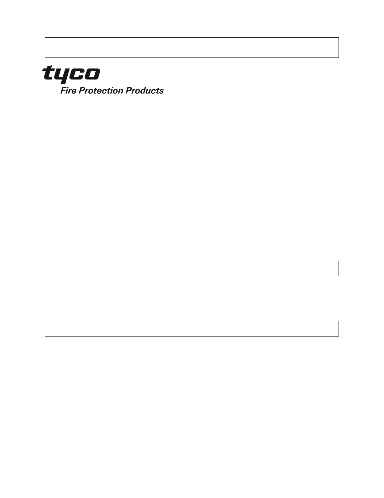
PSU Fault- Output (J8) is an open collector transistor, closing to 0V when active. Example of wiring a
relay to the PSU Fault- output:
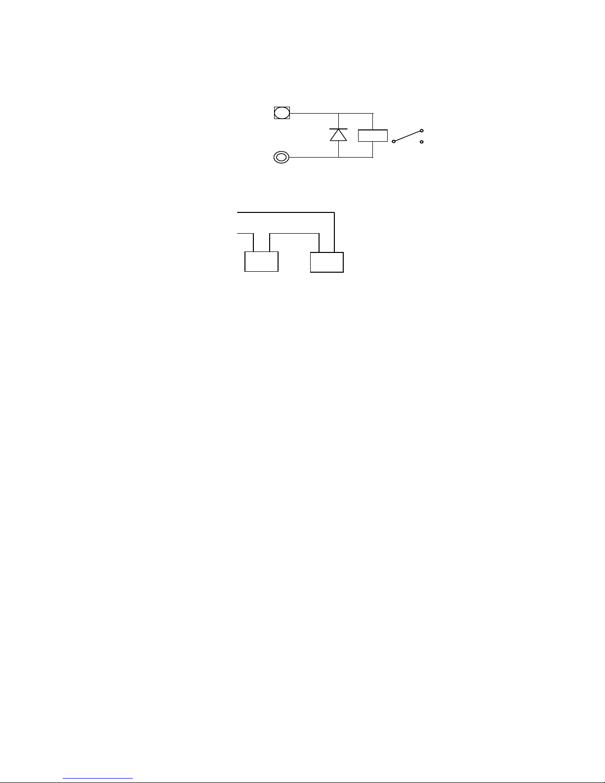
Battery connection: Connect red lead to battery + terminal, connect black lead to battery - terminal.
E.g. For a 24V system connect as shown.
3. CONTROLS & CONFIGURABLE OPTIONS (FIELD ADJUSTMENTS)
Mains On/Off (fuse holder in terminal block acts as a mains switch. Remove fuse to switch off, Fuse is
20x5,1A rating).
- Switches mains (but not the batteries).
Output Adjust (potentiometer PT1 on pcb)
- Adjusts output voltage (and fault thresholds), preset in factory for nominal output.
If field adjustment is required, rotate clockwise to increase voltage, anti-clockwise to decrease.
Timer Disable (remove link LK1 on pcb)
- Disables all automatic battery tests (i.e. battery connected check, hourly and 48 hourly battery
capacity tests).
Current Limit (snip out resistors R13, R14, R15 on pcb).
- Reduces current limit (also charger current rating) if required by battery manufacturer's ratings.
See specifications for details.
Charger Fault (LK2 on pcb)
- If the link is fitted the PSU Fault- output will be active during a charger high or low condition.
Remove the link for AS1603.4 or NZ operation as this feature is not required.
Mains Fail (LK3 on pcb) (software V2.01 onwards)
- If the link is not fitted the PSU Fault output will be active after 90 minutes of continuous mains
failure.
4. STANDARDS COMPLIANCE
To comply with AS1603.4 Clause 2.8.8 an appropriate external battery test load needs to be applied
at the same time as activating the Charger Disable input.
AS4428.5:1998 has two clauses that only need to be complied with if the standard for the product the
PSU is powering requires them. At present there are no such standards. The 1948 PSU cannot meet
Clause 2.2(c) when a short circuit or polarity reversal is applied to the battery terminals. The 1948
PSU does not support disconnecting the battery from the PSU load when the final voltage is reached.
(Clause 2.3(c)).
To signal the loss of mains power (Clause 2.4(a)), remove LK3 (see Section 3 above).
12V
+
-
+ - 12V
+
-
PSU FAULT-
+V
+
-
IN4001
Page 3

LT0232 VERSION 1.14 26 FEBRUARY 2013 PAGE 3 OF 4
5. INDICATORS
Mains On (green LED)
- On when mains is applied and mains fuse is fitted.
Battery/Charger Fault (yellow LED)
- On steady for charger voltage high or low (only when mains is on, inhibited during battery test).
- Flashing for battery not connected, battery voltage low or battery charge capacity low.
Charge/Test (red LED)
- Brightness indicates rate of charge/load current during normal operation.
- Flashing indicates battery test or battery charge capacity test in progress.
6. OPERATION
Automatic Battery Connection Check:
- For this to operate correctly a minimum load is required on either the +V or VNB outputs of:
- 20mA for the 12V supplies;
- 30mA for the 24V supplies.
- Reduces output voltage to 80% for up to 500ms every 30 seconds of continuous mains supply
(uses 50Hz based timer), to allow the battery voltage to be measured.
- If battery low is detected during the test, the output voltage is restored to 100% immediately, the
PSU Fault- output is activated and the Battery/Charge Fault LED flashes until the next battery
connection check passes.
Automatic Battery Charge Capacity Test:
- Reduces output voltage to 80% for up to 90 seconds every hour of continuous mains supply, to
allow the battery voltage to be measured.
- If battery low is detected during the test, the output voltage is restored to 100% immediately, the
PSU Fault- output is activated and the Battery/Charge Fault LED flashes until the next battery
charge capacity test passes.
- If a low battery charge capacity is detected future battery charge capacity tests are carried out at
30 minute intervals until the low battery charge capacity test passes.
Automatic Battery Test:
- Reduces output voltage to 80% for the last 40 minutes of every 48 hours of continuous mains
supply, to allow load to be powered from battery.
- If battery low is detected, the output voltage is restored to 100% immediately, the PSU Faultoutput is activated and the Battery/Charge Fault LED flashes until the end of the 40 minutes.
Reset:
- The timer for the automatic battery checks and tests, and the latched Battery Fault are reset by:
- Removing the Timer Disable link (LK1), or
- Activating the Charger Disable Input (J7), or
- Activating the Timer Disable Input (J18), or
- Turning the Mains switch off.
Note that inputs take approximately 1 second to operate and changes of voltage state take 3-4
seconds to register.
Page 4

LT0232 VERSION 1.14 26 FEBRUARY 2013 PAGE 4 OF 4
7. SPECIFICATIONS
12V 24V
Ordering Codes
Unit FP0765 FP0766, FP0852
PC Board (inc. mains tfmr) PA0854
Electrical
Mains Voltage 230/240Vac (50 Hz) 230/240Vac (50 Hz)
(+6%, -10%) (+6%, -10%)
Mains Fuse 1A, 20 x 5mm 2A, 20 x 5mm
Nominal Output Voltage (+V) 13.7V 27.3V
Nominal +VNB Voltage 14.4V 28.0V
Current Rating 2.0A 2.0A
Nominal Current Limit 2.15A 2.3A
1.9A (Snip R13) 2.0A (Snip R15)
1.75A (Snip R14) 1.7A (Snip R14 & R15)
1.6A (Snip R14 & R13) 1.4A (Snip R13, R14 & R15)
Battery Protection Device RT2 30V, 6A PTC 30V, 6A PTC
(Mounted on pcb) (non-trip at 25°C) (non-trip at 25°C)
Input Fuse F1 3A slow blow, 20 x 5mm 3A slow blow, 20 x 5mm
(In transformer secondary cct)
Heat Loss 25W 45W
Quiescent Current
From battery with mains off 9mA (typical) 10mA (typical)
Additional load in PSU Fault 6mA 6mA
Minimum load for Battery Tests 20mA 30mA
Voltage Monitoring (+V)
Nominal Charger High 14.1V 28.1V
Nominal Charger Low 13.3V 26.5V
Nominal Battery Low 12.1V 24.2V
Inputs/Outputs
Timer Disable- Input (J18) Requires closure to <1V
"Off" current <2uA
"On" current <1mA @ 1V
Charger Disable- Input (J7) Requires closure to 0V, voltage-free switch.
"Off" current < 5uA
"On" current < 0.1mA
PSU Fault- Output (J8) Switches to 0V for fault (open collector transistor)
"Off" State 30V max
"On" State 20mA max, < 0.5V @ 20mA
Compatible Batteries 12V Sealed lead acid with self-limiting charge current.
Some small capacity batteries may require reduced current limit
(refer Battery details).
Mechanical FP0765 & FP0766 FP0852
Cabinet Material 1.2mm mild steel
Finish (Powdercoat) Cream wrinkle BFF-998-CW Oyster Matt
Dimensions 240mm W x 295mm H x 80mm D 360mm W x 230mm H x 130mm D
(Space for up to 2 12V 6.5Ahr batteries) (Space for up to 2 12V 12Ahr batteries)
Lock L&F cam lock keyed 003 L&F cam lock keyed 003
Weight (unpackaged) 3.95kg (12V), 4.20kg (24V) 5.5kg
Environmental Operating -5°C to 45°C max.
Conditions 95% humidity max (non-condensing)
Approvals
AS1603.4:1987 SSL Test Report XF 1596/R1
AS4428.5:1998 SSL Test Report XF 1596/R1
NZS4512:1997 Central Laboratories Test Report 00-527564.04
AS3548 Parkside Laboratory Reports 5263 & 5263A
 Loading...