

Page 1
Section: 8000
I.O.M.: 8906
Issued: 05/06
Replaces: 12/02
PENBERTHY
Installation, Operation and Maintenance
for Penberthy Electronic Water Level
Gauge
Model 12B
Serial No.
Part No.:
Enclosure Type :
Input Power :
Electrode Output :
Alarm & Trip Relay Contact Rating:
Display Outputs :
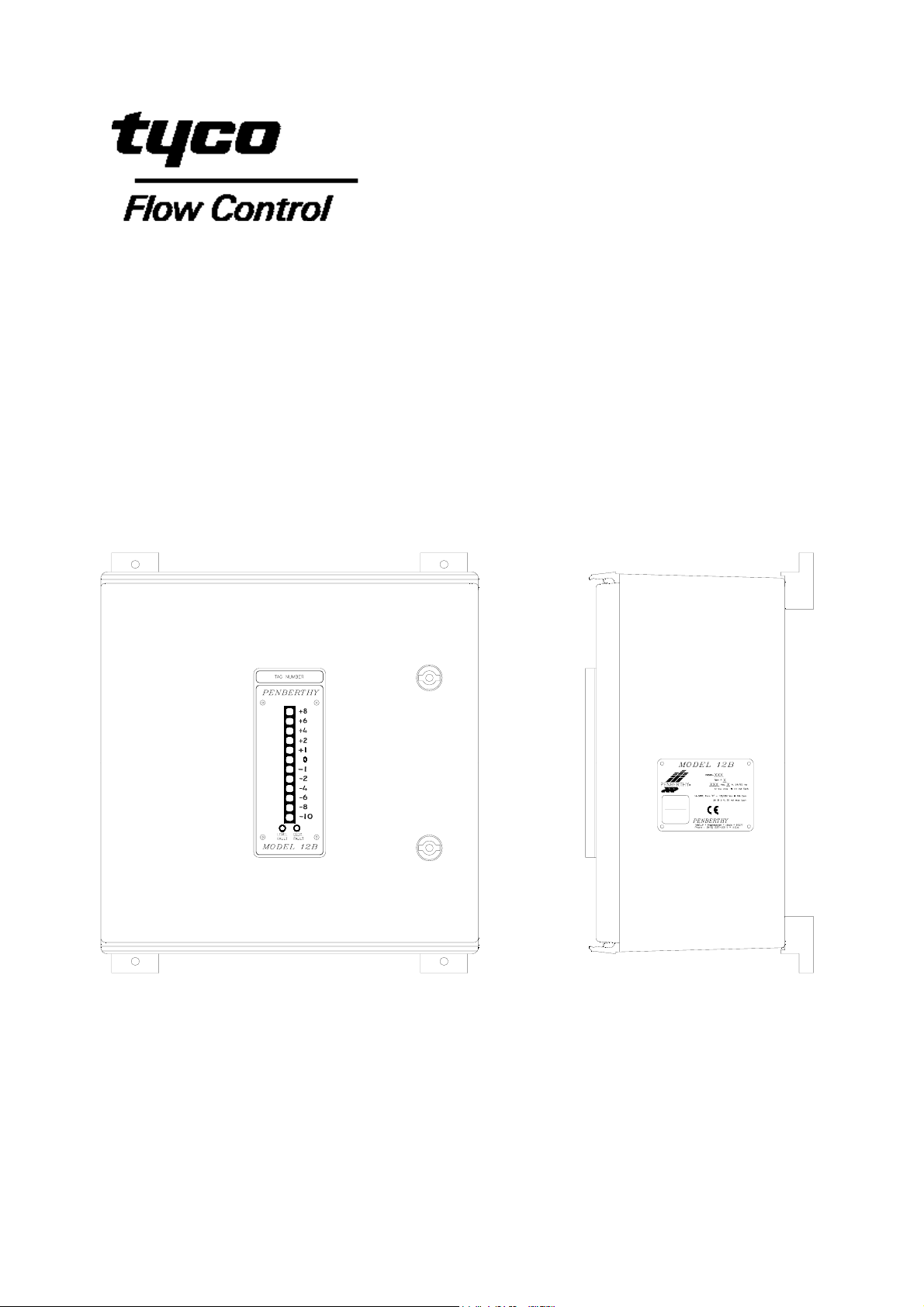
02
*Optional Door Mount Display shown *Standard Electronics Enclosure
with example probe spacing
Installation, Operation and Maintenance
Instructions
Page 2

TABLE OF CONTENTS
Product Warranty . . . . . . . . . ii
1.0 Description . . . . . . . . . 1
2.0 Supply & Installation . . . . . . . . 1
2.1 Packing . . . . . . . . . 1
2.2 Wiring Requirements . . . . . . . 1
2.3 Location of Electronics . . . . . . . 2
2.4 Water Column . . . . . . . . 2
2.5 Probes . . . . . . . . . 3
2.6 Wiring . . . . . . . . . 4
2.6.1 At The Probes . . . . . . . 4
2.6.2 At the Electronic Module . . . . . 5
2.6.3 Display Panel . . . . . . . 6
2.6.3.1 Flash Programming . . . . . 7
2.6.4 Control Output . . . . . . . 7
2.6.5 Electronic Fault Output . . . . . . 7
2.6.6 Level Fault Output . . . . . . 7
2.6.7 Probe Wiring . . . . . . . 8
2.6.7.1 Systems without continuity . . . . 8
2.6.7.2 Systems with Open / Short Circuitry . . . 8
3.0 Startup And Operation . . . . . . . . 8
3.1 Water Column . . . . . . . . 8
3.2 Electronic Module Sensitivity Control . . . . . 9
3.3 System Monitor . . . . . . . . 9
3.3.1 Power Supply Fault . . . . . . 10
3.3.2 Clock Fault . . . . . . . 10
3.3.3 Continuity Monitoring . . . . . . 11
3.4 Probe Installation . . . . . . . . 11
3.5 Probe Removal . . . . . . . . 11
4.0 Detection Circuitry . . . . . . . . 12
5.0 Maintenance . . . . . . . . . 13
5.1 Water Column . . . . . . . . 13
5.2 Probes. . . . . . . . . . 13
5.3 Electronic Modules and Display(s) . . . . . 14
6.0 Spare Parts . . . . . . . . . 15
7.0 Model 12B Specifications . . . . . . . . 15
8.0 Troubleshooting . . . . . . . . . 17
9.0 Disposal at End of Useful Life . . . . . . . 17
10.0 Telephone Assistance / Factory Repair . . . . . . 18
Table of Figures
Figure # 1 – Probe Assembly . . . . . . . . 3
Figure # 2 – Standard Enclosure (up to 12 probes) . . . . . 19
Figure # 3 – Standard Enclosure (13-24 probes) . . . . . 20
Figure # 4 – Wiring Diagram (up to 12 probes) . . . . . 21
Figure # 5 – Wiring Diagram (13-24 probes) . . . . . . 22
Figure # 6 – Motherboard Layout . . . . . . . 23
Figure # 7 – Full-Size Panel Mount Display (up to 12 probes) . . . 24
Figure # 8 – Full-Size Display in NEMA 4X Enclosure (up to 12 probes) . . 25
Figure # 9 – Mini Display in NEMA 4X Enclosure (up to 12 probes) . . . 26
Figure # 10 – Mini Panel Mount Display (up to 12 probes) . . . . 27
Figure # 11 – Full-Size Panel Mount Display (13-24 probes) . . . 28
Figure # 12 – Mini Panel Mount Display (13-24 probes) . . . . 29
Declaration of Conformity . . . . . . . . 30
i
Page 3

PENBERTHY PRODUCT WARRANTY
Tyco Valves & Controls Prophetstown warrants its Penberthy products as
designed and manufactured by TV&C Prophetstown to be free of defects in
the material and workmanship for a period of one year after the date of
installation or eighteen months after the date of manufacture whichever is
earliest. TV&C Prophetstown will, at its option, replace or repair any
products which fail during the warranty period due to defective material or
workmanship.
Prior to submitting any claim for warranty service, the owner must submit
proof of purchase to TV&C Prophetstown and obtain written authorization
to return the product. Thereafter, the product shall be returned to TV&C in
Prophetstown, Illinois, with freight paid.
This warranty shall not apply if the product has been disassembled,
tampered with, repaired or otherwise altered outside of TV&C
Prophetstown factory, or if it has been subject to misuse, neglect or
accident.
The responsibility of TV&C Prophetstown hereunder is limited to repairing
or replacing the product at its expense. TV&C Prophetstown shall not be
liable for loss, damage or expenses related directly or indirectly to the
installation or use of its products, or from any other cause or for
consequential damages. It is expressly understood that TV&C
Prophetstown is not responsible for damage or injury caused to other
products, buildings, personnel or property, by reason of the installation or
use of its products.
THIS IS TV&C PROPHETSTOWN’S SOLE WARRANTY AND IN LIEU OF
ALL OTHER WARRANTIES, EXPRESSED OR IMPLIED WHICH ARE
HEREBY EXCLUDED, INCLUDING IN PARTICULAR ALL WARRANTIES
OF MERCHANTABILITY OR FITNESS FOR A PARTICULAR PURPOSE.
This document and the warranty contained herein may not be modified and
no other warranty, expressed or implied, shall be made by or on behalf of
TV&C Prophetstown unless made in writing and signed by the General
Manager or Director of Engineering of TV&C Prophetstown.
ii
Page 4

INSTALLATION, OPERATION and MAINTENANCE MANUAL
FOR PENBERTHY Model 12B
1.0 Description
The Penberthy Model 12B is an accurate and ultra-reliable instrument for detection of
steam/water presence in subcritical pressure steam generators. The unit pr ovides up to
12 channels per unit (cascadable) for steam/water indication and is complete with
control outputs and internal system fault monitoring, Local and Remote indication and
Level Fault output. Prior to performing any work, personnel responsible for the
installation of the system should read these instructions and become familiar with the
unit. There is a patent pending on the detection and verification circuitry.
Two functional options covered by this I.O.M. may be specified. Check purchasing
documents and verify that the unit received has the options specified.
1.1 Independent Power Line Inputs (a.k.a. dual transformer option) provides
redundancy throughout the entire system.
1.2 Open/short detection
If both options are specified, the unit has at minimum either error detection or double
redundancy for its functions and complies with ANSI/ISA S84.01 – 1996 “Safety
Instrumented Systems”.
The contract drawing supplied for each installation specifies the tapping point spacing
on the water column, the number of probes and their positioning.
This I.O.M. is organized so that article 2 describes the essentials of installation and
wiring to allow initial turn-on. Articles 3 and 4, covering the same basic subjects, may
seem redundant but describe the details of operation beyond initial turn-on. They should
be perused to maximize the utility of the Model 12B.
2.0 Supply & Installation
2.1 Packing
Prior to installing this equipment clean all packing material from around the unit
and inspect for any damage that may have occurred during shipment. Any
claims for loss or damage must be filed by the purchaser with the carrier. A cop y
of the bill of lading and freight bill will be supplied on request by
TV&C – Prophetstown.
2.2 Wiring Requirements
All wiring shall be terminated in a screw type terminal block, a screwed crimp- on
terminal or a screwed lug point.
All wiring for mains in and control relays out shall be dressed away from all
probe and display wiring, bundled and tie wrapped to maintain separation.
Probes and their wiring that are in steam/vapor are essentially antennas and are
susceptible to noise pick-up. To reduce RFI/EMI pick-up, a cable with an overall
shield should be used for the probe/junction box to electronic module
connections. This is a low current line so small wire diameters are acceptable.
The maximum distance is 300’ [91M], refer to section 2.3 for other details.
Remote display wiring should be limited to 1000’ [305M]. Since I•R loss is the
distance limiter – larger wire will allow longer distances. The low level signals
used suggest that an overall shield on this cable is prudent. If the installation is
to be in an area with high electrical noise or to fully comply with EMC directives,
1
Page 5

all enclosures should be specified as metallic or with a conductive coating rather
p
than the basic polymer enclosures.
Wiring shields should be terminated on both ends to the enclosures’ ground lugs
– not to circuit common.
TV&C – Prophetstown recommends that all wiring be enclosed in electrical
metallic tubing (EMI) and that drip loops are established at each enclosur e entry
point. Spiral wrap cable conduits (e.g. Greenfield, BX) should not be used.
2.3 Location of the Electronics
The section on Startup and Operation, Sensitivity Control (Section 3.2) explains
how to set the sensitivity range according to the conductivity of the water in your
application. Water with a low conductivity requires a higher sensitivity and
consequentially has greater noise susceptibility. The highest sensitivity (<1-10
μS) range limits the shielded cable distance between probe and electronic
module to 80 ft. [25m]. The intermediate sensitivity range
(10-100 μS) places an upper limit of 165 ft. [50m] for the shielded cable distance.
The lowest sensitivity greater than about 50 μS allows the shielded cable
distance to be up to 500 ft. [150m]. The coolest, most accessible location for
mounting the electronics is preferred, usually on an outside wall. Dimensions of
enclosures are shown in fig’s 2 and 3.
2.4 Water Column (Refer to Water Column I.O.M. for complete details)
The water column is fixed to the steam drum either by being welded directly to
the isolating valves or welded to flanges that mate with existing flanges on the
steam drum tapping points. A steam inlet line must be installed to provide a free
flow of steam to the Model 12B column. The steam line must slope down toward
the column (a slope of 2% is recommended). When globe valves are used as the
isolation valves, they must be installed with the stem horizontal. Ideally, the
return water leg should be horizontal. This leg may, however, be sloped down to
the drum, in which case it must be insulated. In no case should the steam line be
insulated.
Water Columns with three maximum pressure ratings are available –
850 [58 bar], 1800 [124 bar] and 3000 psi [206.9 bar] design. The fittings on
steam generators of lower pressure usually have a lesser rating. As a result, the
overall rating of a system is governed by the lowest rating of any of the
components.
The metal probe covers should be removed from the water column after it is fully
plumbed into the system and remain off until the system is in service and a
satisfactory inspection of all the probes and the associated wiring is completed.
! W A R N I N G !
The nature of the electronics, the harsh operating environment and the
potential hazards associated with live steam require that only qualified
personnel install and maintain this equipment. Without adequate qualifications,
an operator could allow live steam to escape which may cause property damage
or severe
ersonal injury.
2
Page 6
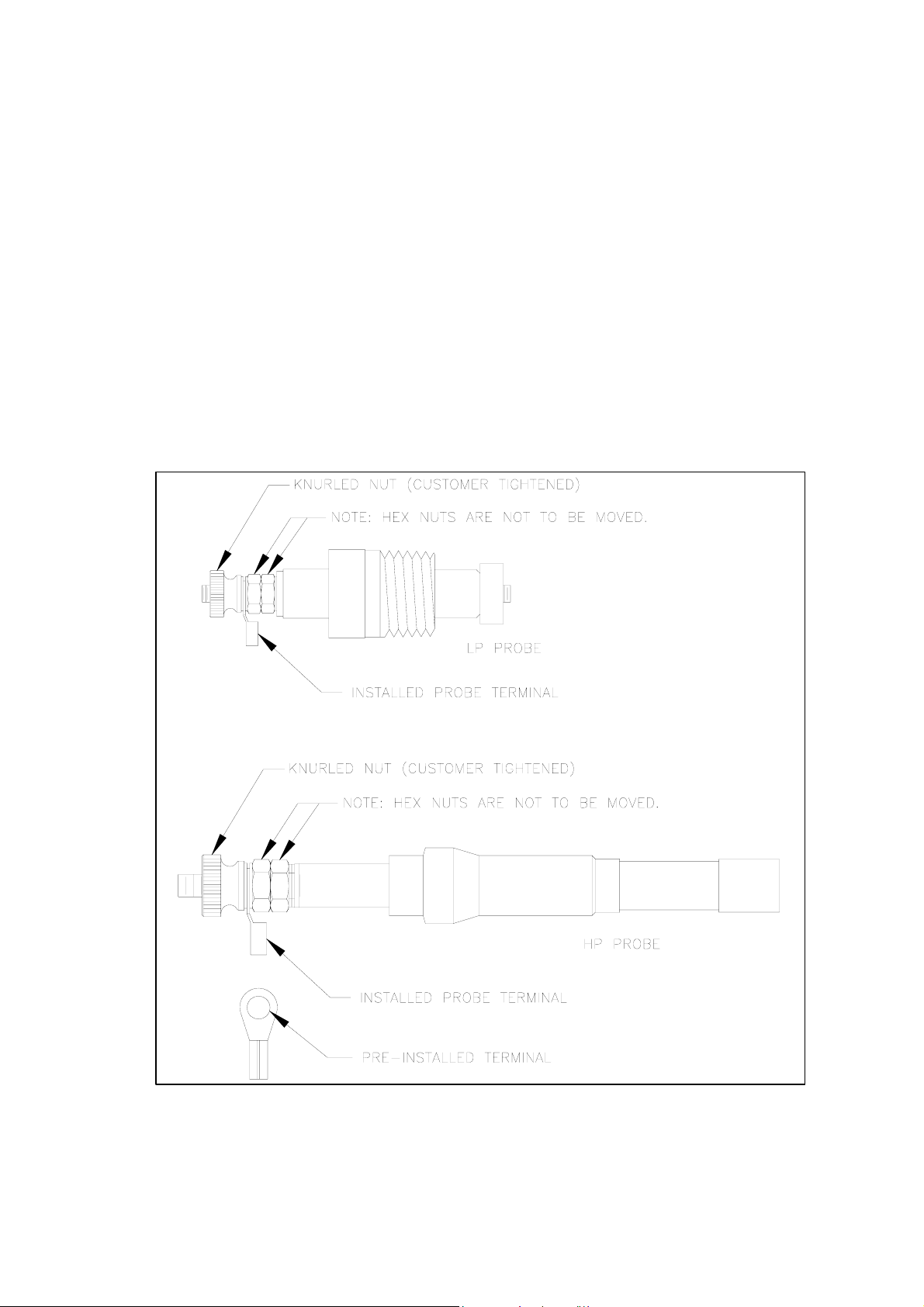
2.5 Probes
The Model 12B is supplied with either of two probe styles. For applications below
525°F [274°C] / 850 psi [58 bar], an economical probe is available with a PTFE
wetted insulator. It can not be used if either parameter (525°F [274°C] or 850 psi
[58 bar]) is exceeded.
For all other applications, probes with the zirconium oxide (ceramic) insulators
must be used. The high pressure (HP) probes are easily recognized by the
brazing between the insulator and the body (fig 1). The two styles of probes are
not interchangeable and will not fit in a receptacle designed for the other, the LP
probe uses a threaded fitting, the HP a compression fitting. In this I.O.M., all
instructions address the HP style probe (see figure 1). Refer to the water
column I.O.M. for details on both the HP and LP probes.
Note: The probe hex nut and hex jam nut located on the post used for the
electrical connection have been pre-torqued to exact specification. If the
hex nuts are inadvertently moved, the probe must be replaced.
Figure 1 – Probe Assembly
3
Page 7
2.5.1 Probes are supplied fully assembled. Probe receptacles on the water
column are ½” swaged fittings.
2.5.2 To ensure the probes remain clean, mount the receptacles so the probes
are exposed to mild fluid circulation. Do not locate the probes in high
velocity steam or water. Probes may be located horizontally or vertically
with the electrical connection up.
2.5.3 Ensure that the receptacle and probe retaining nut threads and sealing
surfaces are clean. The threads on the receptacle and probe retaining
nut should be lubricated with an anti-seize compound to prevent galling
and lower the tightening torque on the threaded parts. Recommended
compounds include:
Silver Goop (Swagelok trade name)
MP-50 Moly Paste (Jet Lube of Canada)
Never-Seez (trade name)
2.5.4 Insert the probe into the receptacle and tighten the probe retaining nut by
hand. With a wrench, further tighten the nut ¼ turn only. Subsequent
connections will be made in a similar manner.
2.6 Wiring (refer to figures 4 and 5)
! C A U T I O N !
Before making any connections, make sure that the power source to be used is
isolated by use of the appropriate circuit breakers and switches so that no work
is being performed with “live wires”, otherwise personal injury or property
damage may result.
Note: All wiring should be in accordance with applicable national
and local codes by qualified personnel.
2.6.1 At the Probes
If the column mounted junction box option is ordered, the unit is prewired from the probes to the junction box mounted on the water column.
Probe to junction box wiring must be high temperature (e.g., mineral /
glass insulated or thermocouple wire).
The cabling between the standard off-column junction box and the
Electronic Module does not require any high temperature capability. It is
recommended, however, the cable should have an overall shield, 18-24
gauge tin or silver plated wire and have a minimum rating of 221°F,
[105°C]. If the junction box is located on the water column, higher
temperature wiring may be required.
The lowest probe on ALL
terminal in the Electronic Module is 1. Wire successively higher probes in
systems is numbered 1 and the corresponding
4
Page 8
the same manner.
Cascaded Electronic Modules (more than 12 channels) may be installed
with probe wiring in numerical series or interleaved. If interleaving is
used, make certain that the low Electronic Module Probe 1 terminal block
location is wired to the lowest probe or the level fault logic will not work.
The wiring method used must be specified so the level fault logic can be
properly programmed at the factory.
Do not run input power through spare conductors in multi-conductor cables
used for probes and display module wiring. Input power is to be run in
separate cable runs.
2.6.2 At the Electronic Module
No wiring access holes are drilled in the enclosure. Access holes may be
placed at any convenient point during installation. Use appropriate
fittings, consider EMI and RFI, also maintain the NEMA/IP rating of the
enclosure. The access hole for the probe wiring should contain only
probe wiring. The access hole for the remote display wiring (if used)
should contain only remote display wiring. (Refer to fig 7 through 10 for
display wiring and dimensions).
It is recommended that the relay out and mains power input each have
their own access hole although this is not mandatory. Dress all mains
carrying conductors away from signal wiring.
To ease installation and wiring, the entire module may be removed from
its enclosure by removing the screws holding the metal back plate. Do
not separate the printed circuit board from the back plate.
For reliable operation, a mains power source with the following
requirements is required:
120 or 240 Vac
Single Phase, 50/60 Hz
40VA / 80VA, depending on configuration
Mains higher than 240 Vac will require the use of a stepdown
transformer. DC voltages will require use of a voltage inverter.
(refer to fig 6, loc 1 and 2)
If a standard unit was specified:
Mains power is connected to TB27 only.
For 120 Vac operation: L1 is “hot”, L2 is “neutral”. A fuse should be
installed at F1. G is for electrical ground.
For 240 Vac operation: L1 and L2 are directly wired. Fuses should be
installed at F1 and F2. G is for electrical ground.
If the dual transformer option was specified:
Mains 1 power is connected as above. Mains 2 power should be sourced
from a different mains supply. Mains 2 power is connected to TB28 only.
5
Page 9

Follow the connections above for mains 1 using TB28. Fuse positions
are F3 and F4 for mains 2.
Earth bonding should be to the earthing lug on the mounting plate.
Mains power is MOV protected. Although the Model 12B uses jumper
set dual primary toroidal transformers, do not attempt to change factory
set mains voltage level unless the MOV’s are also changed to the proper
value.
If a door mounted local display or 4-20 mA loop output was specified, a
ribbon cable connects it to the connector at fig 6, loc 14. Do not use this
connector for any other purpose.
Keep-Outs (refer to fig 6, loc 5 and 16)
Note: Failure to heed these “keep-out” areas may damage the
electronics.
The terminal blocks at the upper left are for factory cascading level logic
– do not use for any purpose. Do not connect any wiring to these
terminal blocks.
The programming pins at the lower right are for the CPLD logic block –
do not use for any purpose. Do not store flash jumpers on these pins.
2.6.3 Display Panel (refer to fig 6, loc 15)
External display panel(s) are connected to the Electronic Module by a
16-20 AWG multi-conductor cable. Shielding is required if electrical
conductors other than those for the Model 12B low voltage display share
the same wiring conduit. Do not use extra cable leads for anything
except display module wiring. Use of these cables for other than what
they were intended may cause damage to the electronics.
The number of conductors required between Electronics and Display
Panel for your system can be calculated as follows:
Minimum conductors required = Number of probes x 2 + 2 (commo n) +
2 (fault LED’s).
Therefore, a twelve probe system requires (12 x 2 + 2 +2) = 28
conductors.
When several display modules are used a maximum of one local and
one remote or two remotes may be directly driven. For more than two,
the displays must be independently powered models. Each module may
be connected in parallel to the Electronic Module terminal strip or daisy
chained from the terminal strip of a preceding display module. Care must
be taken to match the corresponding terminal connections. For daisy
chained connections use heavier gage wire. A smaller remote display
(suitable for desk mounting) is also available.
Light emitting diodes (LED’s) are used on the display module. These
LED’s have an expected 20+ year life and can be replaced only on a
modular basis.
6
Page 10

2.6.3.1 Flash Programming (refer to fig 6, loc 17)
For operationally critical point indication – any green (water) or
red (steam) LED on all displays may be user programmed to
flash. As supplied all LED’s are programmed steady state.
There are two columns each three pins wide. Red LED control
is the left three pin columns; green, the right three pin colum ns.
If the shorting link is placed on the right two pins in a color
column, that LED color/channel will be steady state.
If the shorting link is moved to the left two pins in a column, that
LED color/channel will flash. Probe numbers, color and F(lash)
/ S(teady state) are silk screened on the printed circuit board as
a guide. The flash oscillator frequency may be checked with an
oscilloscope at test point #7 as a 5V ≈ 3Hz square wave.
Note: Do NOT set any of the LED’s to flash if a 4-20mA output
module is used with the system. This will interfere with the
proper operation of the 4-20mA module.
2.6.4 Control Output (water fail-safe) (refer to fig 6, loc 10)
SPDT Form-C contacts are provided for the control output of each
channel. These outputs are designated Relays “1” through “12” for
channels 1 through 12, respectively. Contact Rating:
8 A @ 28 VDC
10 A @ 120 Vac
10 A @ 250 Vac CSA and UL
5 A @ 250 Vac TÜV
Careful consideration should be given to the design of the alarm and trip
logic. Power loss or vessel blowdown could inadvertently shut down the
steam generator or leave the unit without protection. A keyed lock-out
switch, for trips, alarms, etc. is available as an option. The NC/NO/C
terminals are graphically marked at each relay. See detail on fig 4.
2.6.5 Electrical Fault Output (fail-safe)
A SPDT Form-C relay contact is provided to monitor the operation of the
Model 12B. This relay coil is normally energized. Loss of power to the
unit or detection of an internal Electrical Fault condition will cause the
relay to de-energize, opening the contacts. The electrical fault detection
circuit covers clock failure, open and short circuit detection and two
internal power supplies. This feature has variable time delay from 3 to
about 10 seconds. See fig 6, loc 12 for the adjustment potentiometer.
Turn clockwise to increase the length of delay.
2.6.6 Level Fault Output (fail-safe)
The Model 12B is also equipped with a Level Fault relay. A Level Fault
occurs whenever water is detected above steam. Probe 1 is always at
the lowest level. This feature also has variable time delay. The
adjustment potentiometer is on fig 6, loc 13. Turn clockwise to increase
the length of delay.
7
Page 11

2.6.7 Probe Wiring (refer to fig 6, loc 4)
Each electronic module will support a maximum of twelve probes. Each
probe input to the module may have two wires. These are probe wire
(electrode marked “E” = minimum wiring required with all systems) and a
open/short sense wire, marked “S” (optional). Wiring at the probe is via
the crimp type eyelet supplied with each probe. If the eyelet is not used
intermittent operation may result. At least two ground wires must be
connected to the water column ground. Units with more than 12 probes
use two or more electronic modules in a larger enclosure. The num ber of
conductors required between the water column and Electronics for your
system may be calculated as follows:
2.6.7.1 Basic Systems (wired only to “E” on the terminal block)
Minimum conductors required = Number of probes + 2
(ground)
Therefore, a twelve probe system requires (12 + 2) = 14
conductors.
2.6.7.2 Systems with Open / Short Option (two wires at each
probe. One from probe to “E” on the terminal block, the
other to “S” on the terminal block.)
Minimum conductors required = Number of probes x 2 + 2
(ground)
Therefore, a twelve probe system with open/short option
requires (12 x 2 + 2) = 26 conductors.
Note: If this option was specified and is NOT
wired as described in
2.6.7 and 2.6.7.2, the electrical fault indication and relay will
continuously indicate fault.
3.0 Startup and Operation
3.1 Water Column
To place the water column in service the following procedure is recommended:
(1) Inspect the water column to ensure that all the probes are installed and the
associated wiring is correct and all connections are secure. Wiring should
be neatly routed and any contact between the high temperature water
column body or the probe cover should be avoided.
(2) Open the blowdown valve.
(3) Crack the steam block valve and warm up the water column for a period of
3 to 5 minutes with low velocity steam.
(4) At the end of the warm-up period, close the blowdown valve and then fully
open the steam valve.
(5) The water connection block valve should now be opened, or alternately, if
this valve is left closed, the vessel will fill with condensate allowing the
operating range to be verified.
(7) The water block valve must then be fully opened.
8
Page 12

(8) Visually check all the probes for any sign of leaks. Replacement of the probe
cover using the ¼” socket head cap screws will complete the commissioning
of the water column.
(9) The metallic sensing tip of any probe may self-passivate or the probe
insulator may retain a slightly conductive film from processing. A “hot start”
as outlined above will clear any residual passivation or coating. Attempting to
commission a Model 12B using cold water, such as during a hy drostatic test,
cannot guarantee proper probe wetting. The display/relays may therefore
generate a random output commonly called “checkerboarding”. Pre-cleaning
the probes (see section 5.2 (3)) will also eliminate this potential
commissioning problem.
(10) Isolation and blowdown valves should be carefully selected and installed as
outlined in ASME Power Boiler Code, Section 1. Yarway Welbond valves,
Series 5600, are recommended.
(11) During vessel blowdown, isolation or testing, some form of interlocking
bypass of the high and low water control outputs may be required to avoid
boiler tripping.
3.2 Electronic Module Sensitivity Control
Inspect the module to ensure that all electrical connections are made and
properly protected. The sensitivity required for the water conductivity range to be
detected should have been specified when the system was ordered, if not, the
default sensitivity of 10 – 100 μS was supplied. If the sensitivity is not correct,
proper replacement resistor packs should be obtained by contacting TV&C –
Prophetstown with the conductivity of water used. The proper resistor packs are
placed into sockets at R444 and R445 (ref: fig 6, loc 6). These are standard dual
in-line (DIP) IC type sockets. Do not bend any resistor pack lead during insertion.
Note: All channels will be set to the same conductivity range.
The factory default setting is: Conductivity 10 - 100μS nominal.
After setting the sensitivity, power may be supplied to the unit by use of the
external circuit breaker. The unit is now operational.
3.3 System Monitor (a.k.a. Electrical Fault)
The Model 12B is equipped with a SPDT fault annunciating relay that monitors
critical internal electronic circuitry. The fault relay is de-energized when a fault is
present. If the mains power to the device is lost or if one of the three conditions
listed below were to occur the fault relay will de-energize.
9
Page 13

3.3.1 Power Supply Fault
Two separate power supplies provide detection power for the Model 12B.
The output of both power supplies are diode shared such that if one
supply fails the remaining supply will carry 100% of the system load.
Each supply has its own full bridge rectifier, filter and a regulator. For the
basic unit, the low voltage transformer with fused input is shared by the
two DC supplies. With the dual transformer option using two independent
power mains, each transformer supplies electrical energy to one DC
power supply. If a fault were to occur within any part of this circuit the
fault circuit would de-energize the electrical fault relay and turn on LED
27 or LED 28 (ref: Fig 6, loc 3) to indicate the fault area and also turn on
the electrical fault LED on the display. If both supplies fail, check the
fuses. Replacement fuses should be rated at 2A 250 V for 120 Vac
mains power or 1A 250 V for optional 240 Vac mains power. One fuse is
used in the “hot” line of 120 Vac supply, one fuse in
Vac supply. The fuses have a polymer guard to prevent personnel
contact, always replace it after changing fuses. There are also two 5
VDC power supplies with diode sharing and thermal and electrical
overload protection. If both 5 VDC power supplies fail the indication is a
loss of all displays and all relays go to the de-energized state.
Power supply test points are numbered 1 to 6 (ref: fig 6, loc 4).
TP1 and TP4 should be at +12 VDC.
TP2 and TP5 should be at -12VDC.
TP3 and TP6 should be at +5.75 VDC.
All with a tolerance of ±0.25 VDC.
each line for 240
! C A U T I O N !
Make sure the mains supply is isolated before replacing the fuse. Working on an
electrically “hot” circuit could cause personal injury and property damage.
3.3.2 Clock Fault
There are three clock circuits on the Model 12B. Clock 1 operates at 20
Hz and is the steam/water discriminating frequency. If this clock circuitry
fails, the Model 12B will turn on LED 1 (see fig 6, loc 11) and the
electrical fault LED on the display. Loss of this clock is replaced
automatically by a line frequency (50/60Hz) sample (Clock 3). Sensitivity
will be reduced but the unit should still operate if the sensitivity resistor
pack value was properly chosen. Clock 2 at 5KHz is used for open/short
detection. If it fails, LED 2 (see fig 6, loc 11) will turn on as well as the
electrical fault LED on the display. Steam/water detection will still be
operational. Open/short LED’s (see fig 6, loc 9) for all channels will also
turn on with the loss of either primary clock.
10
Page 14

3.3.3 Continuity Monitoring (if open / short option was ordered)
When two wires are connected to each probe, cable continuity testing is
continuously performed. Connect one wire from the “E” (electrode)
terminal to the probe and another wire from the “S” (sense) terminal to
the probe. If either of these wires are broken or shorted or a probe is
shorted, a continuity fault occurs, the electrical fault relay is deenergized, the Electrical Fault LED on the display is turned on and a
yellow LED corresponding to the channel is turned on. (Ref: fig 6, loc 9).
If the break is in the wire connected to the “S” terminal, the level will still
show proper steam/water status. If the break is in the wire connected to
the “E” terminal, that channel will always show steam. If single wiring
only is used, the continuity function will not work.
(Refer to fig 6, loc 8).
Tables of test points and fault condition determination follow.
Probe # Left TP# Right TP# LED #
12 26 27 15
11 35 36 21
10 38 39 23
9 41 42 25
8 29 30 17
7 32 33 19
6 23 24 13
5 17 18 9
4 20 21 11
3 14 15 7
2 11 12 5
1 8 9 3
Condition Left TP Right TP Note
Normal Operation
Short < +1 VDC > -1 VDC Display and Relay indicates water
“E” wire open < +1 VDC
“S” wire open
3.4 Probe Installation (See Section 2.4)
3.5 Probe Removal
(1) Ascertain that the water column is properly isolated from the steam drum
(2) Loosen the probe retaining nut approximately 1 turn and then free the probe
≈ +9 VDC ≈ -9 VDC
≈ +9 VDC
The shorted probe option works with a fixed reference. It changes to
fault condition upon the detection of the equivalent of ≈1000 μS water
(standard setting). This switching point may be changed to indicate fault
at any user determined conductivity point by replacing the three shortcircuit resistor packages (Refer to fig 6, loc 7). If applied, this option will
allow early detection of changing water chemistry. See section 5.3 for
more details on changing resistor packages.
and all pressure has been relieved.
≈ -9 VDC
> -1 VDC Steam/Water Display and Relays Normal
11
Normal Display/ Relay
Display and Relay indicates steam
Page 15

to verify all pressure has been relieved. The metal-to-metal sealing surface
initially may cause the probe to stick, so carefully free the joint by tapping
the probe on the metal body. Do not strike the zirconia insulator and do not
use a wrench to turn the probe hex nuts.
(3) After the probe becomes free, loosen the probe retaining nut fully and
remove the probe.
(4) The threads on the probe receptacle and probe retaining nut should be re-
lubricated each time the probe is reinserted (refer to section 2.4 for probe
reinsertion).
4.0 Detection Circuitry
A low-voltage ± symmetrical mixed sine wave (net integral zero value) is generated in
the Model 12B System. This signal is buffered and connected through a resistor to the
probe field terminal blocks. (ref: fig 6, loc 4)
Note: If clock 1 fails, line frequency sampling is used for back-up detection but
± symmetry can not be guaranteed and a small offset voltage may develop.
When the probe tip is immersed in water a signal current bleed path to ground is
completed by the conductivity of the water. Current flow through the circuit causes a
voltage drop to appear across a sensitivity resistor. The voltage is compared to a fixed
reference voltage. When the voltage drop exceeds the reference voltage the amplifier
outputs a signal indicating the presence of water. A green LED turns on when the probe
is in contact with water, (ref: fig 6, loc 9). One test point is provided per channel for
troubleshooting. When the probe is submerged, the voltage should be ≈ 0, when in air or
steam the voltage should be +1.4 VDC (±0.3). Probe channel to test point numbers are:
Frequency filters separate the two components of the sinewave and also reduce
noise pick-up by the probes and their associated wiring.
Channel Test Point
12 28
11 37
10 40
9 43
8 31
7 34
6 25
5 19
4 22
3 16
2 13
1 10
12
Page 16

5.0 Maintenance
Each boiler installation is subject to varying operating and water conditions. Generally,
the higher operating pressure units (>1800 psi [125 bar]) have improved water treatment
and, as such, maintenance is minimized.
5.1 Water Column
A specific maintenance program is difficult to detail but the following out lines the
minimum required:
(1) The water column should be blown down periodically and visually inspected
(2) The operating range of the Model 12B should be verified at this time by
5.2 Probes
! W A R N I N G !
for leaks every 3 months.
allowing the water column to fill with condensate (see Startup and
Operation sect 3.1).
Before servicing the probes, ensure that the water column is properly isolated
from the system, all pressure has been relieved and the unit cooled to an
acceptable level, otherwise severe personal injury and property damage may
occur.
Note: The voltage to the probes from the electronic module is a symmetrical sine
wave 12 Vac RMS or less, resistively isolated. The power, therefore, does not
have to be turned off when working with the probes. Probe tips may be
shorted to ground but should never be subjected to another voltage source.
Assuming trouble-free operation, probes should be inspected after the first 12
months. Thereafter, they should be inspected as required, depending upon the
degree of contamination found at first inspection.
(1) Loosen the probe retaining nut approximately 1 turn and then free the
probe to verify all pressure has been relieved. The metal to metal sealing
surface initially may cause the probe to stick, so carefully free the joint by
tapping the probe on the metal body. Do not strike the zirconia insulator
and do NOT turn the probe hex head nuts or the probe will be destroye d.
(2) After the probe becomes free, loosen the probe retaining nut fully and
remove the probe.
(3) Severe deposits on the probes indicate that inspection should be more
frequent. A common household powdered cleaner may be used to clean
the probe body and the insulator. After cleaning, the probes should be
wiped off with a dry, clean cloth. Do not immerse the probe in liquids.
Probes that show any signs of damage, insulator cracking, or steam
leaks must be replaced immediately. Do not attempt disassembly of the
probe components.
13
Page 17

(4) The integrity of the probe can be checked by using an ohmmeter.
p
Resistance measurement across the insulator of 10 MΩ or greater
indicates the probe is performing satisfactorily. If the system is selected
for detection of high conductivity water (greater than
25 μS), a probe resistance measurement of 1 MΩ or greater may be
considered satisfactory. For the ultra high sensitivity system o ption (<1μS
conductivity), 20 MΩ is minimum.
(5) After the probes have been inspected, cleaned and tested, they can be
installed following the steps outlined in the probe installation procedure
section.
(6) Do not leave an open probe receptacle on the water column. If for any
reason a probe is not immediately re-installed, the port should be
plugged with Penberthy HP Part No. 964584-19 or Penberthy Part #
10675-022 for LP probes and tightened following the probe installation
procedure.
(7) The unit can now be returned to service by following the steps outlined in
the start-up procedure (see Startup and Operation, section 3).
5.3 Electronic Modules and Display(s)
! C A U T I O N !
Any malfunction of the equipment should be attended to immediately. Although any
single channel will fail safe, the overall package is designed for continued
operation. Compounding faults, however, could defeat the internal self-diagnostic
logic, providing misinformation to the operator and possibly subjecting the boiler to
otential hazard or nuisance trips.
The Model 12B is factory set to detect water with 10μS conductivity. If the
operating water conductivity is significantly different from this value, contact the
factory for replacement sense resistor packages (two per board). The operating
water conductivity will be needed to determine the proper resistor value. When
ready to install the new resistor packages, follow these steps (refer to figure 6,
location 6):
(1) Remove power to the unit.
(2) Ensure that proper precautions are taken to prevent electrostatic
discharge to the electronics. Using fingers, remove the old resistor
package by pulling straight out from the socket. A slight rocking motion
can be used if needed. Do not use tools to pry the package out. Do not
use excessive force.
(3) Place the new resistor package into the socket, ensuring all of the pins
are engaged in the socket. Press firmly straight down to seat the resistor
package. Do not use excessive force.
14
Page 18

(4) Restore power to the unit.
If the continuity monitoring option was ordered, the shorted wire detection is
factory set to indicate fault condition upon the detection of the equivalent of
≈1000 μS water. If the water conductivity sense resistors are changed, the three
short-circuit resistors should be changed at the same time. Refer to figure 6,
location 7 and use the procedure outlined above.
6.0 Spare Parts
The following spare parts are recommended as a minimum set for stocking by the
user:
Probes:
12 point Single Module – stock 2
24 point Two Module – stock 4
36 point or more Systems – stock 6
1 Relay (requires pcb through hole soldering to replace)
A copy of this I.O.M.
Probes are available only as complete new assemblies.
Consult your Tyco or Penberthy distributor or TV&C-Prophetstown
for repair Modules.
7.0 Model 12B Specifications *
Standard Sensitivity:
Input Voltage: 105-130 Vac or optional
210-260 Vac – MOV protected
Frequency: 50-60 Hz
Power (max): depends on system configuration
80 VA dual transformer system
40 VA single transformer system
Output Voltage:
Probes: 12 Vac RMS maximum, resistor isolated
Relay Contact: 8 AMP 28 VDC
10 AMP @ 125 Vac (resistive)
UL & CSA: 10 AMP @ 250 Vac (resistive)
TÜV: 5 AMP @ 250 Vac (resistive)
Operating Temperature:
Electronics: 32 – 160°F [0°C –70°C]
FOR USE IN 121°F [50°C] MAXIMUM AMBIENT (without local display)
FOR USE IN 104°F [40°C] MAXIMUM AMBIENT (with local display)
Standard Column: 850°F [455°C] maximum
Standard Enclosure Rating: NEMA 4X [IP66]
≥ 1μSiemens (10 – 100 μS default)
15
Page 19

Wiring Specification:
Junction Box to 300V, 221°F [105°C]
Electronic Module: 18-24 AWG or larger shielded
PVC, 14 or 26 conductor
Electronic Module 300V, 221°F [105°C]
To Remote Display: 16-20 AWG or larger
PVC 28 conductor
Dimensions/Weights: Electronic Module
(Up to 12 Probe System) 16” [40.6 cm] H x
16” [40.6 cm] W x
8” [20.3 cm] D
Single Transformer 20 lbs [ 9 kg]
Dual Transformer 22 lbs [10 kg]
Manufacturing Standards:
Column: ASME Section 1, ASME B31.1
Electronics: CSA 22.2
NFPA - 70 (NEC)
89/336/EEC
73/23/EEC
Standard Options:
Door Mounted Local Display
Additional Remote Displays: Slaved or
Independently Powered
Note: Displays are available in two sizes, standard and mini.
Displays may be ordered in an enclosure or for panel mounting.
Dual Transformer using two separate mains input
Open/Short Detection
Metallic enclosure for EMI/RFI control – Stainless Steel or Carbon Steel
Keyed Lock-Out Switches
< 1μS sensitivity
Cascaded units to n channels
Specify: Series or Interleaved Probe connections
Shorted probe detection level set to user specified conductivity trip point
(±5% with hysteresis) to indicate change in water chemistry.
4-20 mA instrumentation loop output, galvanic isolation, with geometrically
proportional driven integrative state change
16
Page 20

*Specifications and descriptions are subject to change without notice.
8.0 Troubleshooting
Water Column: Refer to section 5.1
Sensitivity/Conductivity: Refer to sections 2.2 and 3.2
Probes: Refer to sections 2.4, 3.5 and 5.2
Probe Wiring: Refer to sections 2.2, 2.5.1, 2.5.2, 2.5.7 and fig 4, 5 & 6
Line Power/Fuses: Refer to section 2.5.2 and 3.3.1
Power Supplies: Refer to section 3.3.1
S/W discrimination: Refer to section 4.0
Clock Fault/Backup: Refer to section 3.3.2
Electric Fault: Refer to section 3.3
Level Fault: Refer to sections 2.5.1 and 2.5.6
Continuity (Open/Short): Refer to section 3.3.3
Control Relay: Refer to section 2.5.4
Display Module Wiring: Refer to section 2.5.3 and fig 4, 5, 8, 9 & 10
LED Flash: Refer to section 2.5.3.1
The electronics module and display module(s) are constructed with surface mounted
electronics. Field repair is not practical except for replacement of relays.
9.0 Disposal at End of Useful Life
The Model 12B may be used in a variety of fluid applications. By following the appropriate
national and industry regulations, the user must determine the extent of preparation and
treatment the Model 12B must incur before its disposal. A Material Safety Data Sheet
(MSDS) may be required before disposal services accept certain components.
Metal, glass and polymers should be recycled whenever possible. Refer to order and
TV&C - Prophetstown Material Specification sheets for materials of construction.
The OSHA Hazard Communication Standard 29CFR 1910.1200, states that the standard does not apply to “articles”. The standard defines an article
as:
The above named products fall within the definition of an ‘article”, no Material Safety Data Sheets are available or are required. Our product is
manufactured as an “end product”.
If the product is a weld end the following applies.
WARNING: Materials used in manufacture of Penberthy products are considered in a stable condition when shipped. However, under certain
conditions purchasers could create potential hazardous conditions by their future operations.
Caution: Welding, cutting, burning, machining or grinding of this product can generate toxic dust and fumes of potentially hazardous ingredients. The
dust or fumes can cause irritation of the respiratory tract, nose, throat, skin and eyes. It may cause temporary or permanent respiratory disease in a
small percentage of exposed individuals. Use moderate ventilation when grinding or welding. Avoid breathing dust, fumes or mist. Avoid prolonged
skin contact with dust or mist. Maintain dust levels below OSHA and ACGIH levels. Use protective devices. Wash hands thoroughly after contact
with dust before eating or smoking.
*A manufactured item formed to a specific shape or design for a particular use which does not release or otherwise expose an employee
to a hazardous chemical under normal conditions of use”.
RIGHT TO KNOW LAWS AND OSHA STANDARD 29CFR (1910.1200)
Material Safety Data Sheets on the following Penberthy product:
Model 12B
For emergency information contact:
Tyco Valves & Controls, L.P. Prophetstown
320 Locust St., Prophetstown, Illinois 61277
Phone: 815-537-2311
Fax: 815-537-5365
E-mail:boilertrimteam@tycovalves.com
17
Page 21

10.0 Telephone Assistance / Factory Repair
If you are having difficulty with your Model 12B, contact your local Tyco / Penberthy
distributor. You may also contact the factory direct at (815) 537-2311 and ask for an
applications engineer. So that we may assist you more effectively, please have as much of
the following information available when you call:
Model #
Serial #
Name of the company from whom you purchased the Model 12B
Invoice # and date
Process conditions (pressure, temperature, cycle rate, etc.)
A brief description of the problem
Troubleshooting procedures that failed
If attempts to solve your problem fail, you may request to return your Model 12B to the
factory for intensive testing. You must obtain a Return Authorization (R.A.) number from
TV&C - Prophetstown before returning anything. Failure to do so will result in the un it being
returned to you without being tested, freight colle ct. To obtain an R.A. n umber, the following
information (in addition to that above) is needed:
Reason for return
Person to contact at your company
“Ship To” address
There is a minimum charge of $100.00 for evaluation of non-warranty units. You will be
contacted before any repairs are initiated should the cost exceed the minimum charge. If
you return a unit under warranty, but is not defective, the minimum charge will apply.
18
Page 22

:
g
n
i
t
a
2
R
0
t
c
a
t
n
o
C
y
:
a
l
:
t
:
e
u
s
p
R
e
t
p
t
u
:
p
y
u
p
i
t
T
O
r
r
u
e
T
:
e
e
O
.
w
r
d
o
o
&
u
o
y
P
N
s
r
a
m
o
t
l
t
t
r
l
c
p
u
r
c
a
e
s
p
n
l
i
l
a
n
E
P
E
I
D
A
.
o
N
l
a
i
r
e
S
Figure 2 – Standard Enclosure (up to 12 Probes)
19
Page 23

:
g
n
i
t
2
a
R
0
t
c
a
t
n
o
C
y
:
a
:
l
t
:
e
u
s
R
p
e
t
p
t
u
:
p
y
u
i
p
T
r
r
O
t
e
u
T
e
:
e
w
O
r
.
d
o
&
u
o
o
y
P
s
r
N
m
a
o
t
t
l
r
t
l
c
p
u
c
a
r
e
s
p
l
l
a
i
n
n
A
E
E
P
I
D
.
o
N
l
a
i
r
e
S
7
4
8
0
1
2
3
5
6
2
7
1
8
4
5
9
0
2
6
2
2
3
1
2
5
4
0
4
0
5
1
1
1
1
1
1
1
1
1
1
Figure 3 – Standard Enclosure (13-24 Probes)
1
0
3
2
6
9
1
7
6
3
9
7
7
9
8
8
6
4
1
3
5
9
2
8
8
4
2
0
4
9
6
3
5
5
6
5
2
1
3
2
3
4
20
Page 24

Figure 4 – Wiring Diagram (up to 12 Probes)
21
Page 25

Figure 5 – Wiring Diagram (13-24 Probes)
22
Page 26

Figure 6 – Motherboard Layout
23
Page 27

Figure 7 – Full-Size Panel Mount Display (up to 12 Probes)
24
Page 28

Figure 8 – Full-Size Display in NEMA 4X Enclosure (up to 12 Probes)
25
Page 29

Figure 9 – Mini Display in NEMA 4X Enclosure (up to 12 Probes)
26
Page 30

Figure 10 – Mini Panel Mount Display (up to 12 Probes)
27
Page 31

Figure 11 – Full-Size Panel Mount Display (13-24 Probes)
28
Page 32

Figure 12 – Mini Panel Mount Display (13-24 Probes)
29
Page 33

TV&C – Prophetstown
≈ DECLARATION of CONFORMITY ≈
In conformance with ISO/IEC Guide 22 - 96
12B.DC r 0
Manufacturer's Name: Tyco Valves and Controls B Prophetstown, L.P.
Manufacturer's Address: 320 Locust Street
Prophetstown, IL 61277-1147 U.S.A.
Product:
Type of Equipment: Electronic Water Level Gauge
Equipment Class: Industrial Instrumentation
Model Designation: Penberthy 12B
The product described above is in conformity with:
Standards:
CISPR 11 Radiated Emissions
EN55011, Amend A1 EM Disturbance
EN61362-1 Industrial Immunity
EN61000-4-2/IEC801-2/IEC1000-4-2 Electrostatic Discharge
EN61000-4-3/IEC801-3/IEC1000-4-3/ENV50140 Radiated
Electromagnetic Fields
EN61000-4-4/IEC801-4/IEC1000-4-4 Electrical Fast
Transient
EN61000-4-5/IEC801-5/IEC1000-4-5/ENV50142 Surge (Lightning)
EN61000-4-6/IEC801-6/IEC1000-4-6/ENV50141 RF Conducted (CW)
EN61000-4-8/IEC801-8/IEC1000-4-8 50Hz Radiated Susceptibility
EN61000-4-11/IEC801-11/IEC1000-4-11 Voltage Dips and Variations
Directives:
73/23/EEC Low Voltage
89/336/EEC Electromagnetic Compatibility
When installed per instructions in this I.O.M., Part # 18LC6-019
Date: 24 August 2002 Signature:
Prophetstown, IL U.S.A. Name: David J. Williams, C.Q.E.
Position: Quality Assurance Manager
Technical Construction File is available at stated address. Signatory is contact person.
30
Page 34

Notes:
31
Page 35

Notes:
32
Page 36

Tyco Valves & Controls, L.P. Prophetstown
320 Locust St., Prophetstown, Illinois 61277
Phone: 815-537-2311
FAX: 815-537-5387
Printed in USA
Part No. 18LC6-019
© 2006 TV&C, L.P. Prophetstown, All Rights Reserved
33
 Loading...