

Page 1
Tyco SNMP Managed Media Converters Page 1
SNMP Managed Media Converter
Chassis and Converters
___
Product User Guide
Chassis Product Number
0-1591500-x
0-1591500-x ©Tyco Electronics 2004 Issue 1.2
Page 2

Tyco SNMP Managed Media Converters Page 2
0-1591500-x ©Tyco Electronics 2004 Issue 1.2
Table Of Contents
Introduction.................................................................................................... 4
Features ................................................................................................................ 5
Software Features ................................................................................................. 5
Disclaimer.............................................................................................................. 6
Warranty................................................................................................................ 6
Getting Support ..................................................................................................... 7
Package Contents ................................................................................................. 8
Management Methods ...................................................................................9
Console Management............................................................................................ 9
Telnet Management............................................................................................... 9
Web Based Management ...................................................................................... 9
SNMP Network Management ................................................................................ 9
Hardware Description.................................................................................. 10
Front & Rear Panel.............................................................................................. 10
Installation....................................................................................................11
Pre-Installation Requirements.............................................................................. 11
DC Power Supply Connections ........................................................................ 11
Desktop Installation ............................................................................................. 12
Rack-mounted Installation ................................................................................... 12
Applying Power.................................................................................................... 13
Simple Diagnostic Test ........................................................................................ 13
Quick Start Guide.........................................................................................14
LED Indicators ..................................................................................................... 15
Management Card LED Indicators ................................................................... 15
Media Converter LEDs..................................................................................... 16
Detailed Configuration ................................................................................18
Using a Local Console to Connect to the Chassis................................................ 18
Logging into the Chassis.................................................................................. 18
Main Menu........................................................................................................... 19
Device Settings Menu.......................................................................................... 21
Modules Settings Menu ....................................................................................... 23
Redundant Power Status Menu ........................................................................... 24
Event Log Menu .................................................................................................. 25
SNMP Trap Menu................................................................................................ 27
Secure IP for Telnet, HTTP and SNMP Menu...................................................... 28
Page 3

Tyco SNMP Managed Media Converters Page 3
0-1591500-x ©Tyco Electronics 2004 Issue 1.2
Save Current Settings Command ........................................................................ 29
Factory Default Settings & Reboot System Command......................................... 29
Reboot System Command................................................................................... 29
Web-Based Management ............................................................................30
System Login....................................................................................................... 30
Modules Settings Menu ....................................................................................... 32
Module Controls............................................................................................... 33
UTP (RJ-45) Port Controls ............................................................................... 33
Fibre Port Controls........................................................................................... 34
Notes Field....................................................................................................... 34
Apply Settings .................................................................................................. 34
Save Configuration Settings............................................................................. 34
Port Counters Screen .......................................................................................... 35
IP Config Menu.................................................................................................... 36
Change The IP Address Values ....................................................................... 36
Change User And/Or Password ....................................................................... 36
Save Configuration Settings............................................................................. 36
SNMP Configuration Menu .................................................................................. 37
Save Configuration Settings............................................................................. 37
Event Log Screen ................................................................................................ 38
Misc Settings Screen........................................................................................... 39
Save and Reboot Menu ....................................................................................... 40
Save Current Settings...................................................................................... 40
Factory Default Settings & Reboot ................................................................... 40
Reboot System................................................................................................. 41
Upgrade Firmware Menu ..................................................................................... 41
Web Browser Java Settings........................................................................ 42
Additional Notes............................................................................................... 45
Product Specifications................................................................................ 49
Page 4
Tyco SNMP Managed Media Converters Page 4
Introduction
This professional grade, managed media converter chassis solution enables LAN
workgroups and network users to be connected by a fibre path to remote switches,
routers and servers etc. The Ethernet circuits passing through the chassis are fully
managed and enable the network manager to have a high degree of control over the
system.
Link defects and other circuit problems are promptly reported to enable the network
manager to manage and control the network to a much higher level than using basic
un-managed media converters.
The distant end optical devices can be any 100Base-FX or Gigabit Ethernet media
converter or LAN switch/router port. These remote devices cannot controlled or
configured by this SNMP managed chassis product.
Meeting all the relevant standards for 10Mbit/s, 100Mbit/s and Gigabit Ethernet,
installation is ‘plug-and-play’ and requires no technical knowledge.
The hot-swappable managed media converters cards support ST, MT-RJ and SC
single and multimode fibre formats.
With support for hot-swappable management card, dual-redundant and hot-swappable
AC and DC power packs, this managed chassis system delivers a very robust solution
for critical applications.
16
1
Figure 1 - Typical Managed System
0-1591500-x ©Tyco Electronics 2004 Issue 1.2
Page 5

Tyco SNMP Managed Media Converters Page 5
0-1591500-x ©Tyco Electronics 2004 Issue 1.2
Features
• Chassis supports up to 16 hot swappable media converter cards
• Fully manageable through Web browser, Telnet, SNMP or console interfaces
• Compatible with all standard 100Mbits/s and Gigabit optical interfaces
• Supports full and half-duplex auto-negotiation together with N-Way capability
on all STP/UTP ports
• Link Loss Forwarding fully supported
• Integral event log
• SNMP traps fully supported
• SNMP MIB II and private MIB
• Management security by secure IP address mode
Software Features
Management
Telnet, Web, and Console (RS-232)
MIBS
RFC 1213 MIB II, Private MIB
Software Upgrade
Firmware upgrade via web interface
Link Lost Forward
Each module can be configured to support link loss
forwarding using the Web or console menu interfaces.
Management
Telnet, Web and Console (RS-232)
SNMP Trap Node
Up to 4 Traps supported.
SNMP Trap
SNMP traps support :- Link down, Link up, Power module
status change, authorization fail, Module plug in and plug
out, chassis configuration change, module configuration
change.
IP security
IP security support for telnet, HTTP and SNMP access.
Up to 4 different IP addresses can be supported.
Events log
Up to 4095 events can be recorded.
Table 1 – Key Software Features
Page 6

Tyco SNMP Managed Media Converters Page 6
0-1591500-x ©Tyco Electronics 2004 Issue 1.2
Disclaimer
Tyco Electronics makes no representation or warranties with respect to the contents
hereof and specifically disclaims any implied warranties or merchantability or fitness
for any particular purpose. Further, Tyco Electronics reserves the right to revise this
publication and make changes from time-to-time in the content hereof without
obligation of Tyco Electronics to notify any person of such revision or changes.
Warranty
Full details of the generic limited lifetime warranty scheme are available on the web
site at:-
http://www.lan-electronics.com/support.htm
Tyco Electronics (Active LAN Products) warrants its products to be free from defects in
material and workmanship, under normal use and operation for the lifetime of the
product from the date of purchase from an authorised vendor, subject to the conditions
and exclusions below:-
1. This warranty does not cover any damage to the products that resulted from
accident, abuse, misuse, natural or personal disaster, or any unauthorised
disassembly or modification, or operation in a manner contrary to the instructions,
or shipment of the product to the Tyco Support Centre.
2. The products are not designed, manufactured or intended for use in hazardous or
critical environments or in activities requiring emergency or fail-safe operation or in
any other activity or application in which failure of the product may pose the risk of
physical injury or death or environmental harm. Tyco Electronics (Active LAN
Products) specifically disclaims any express or implied warranty of fitness for any
dangerous application.
3. Except for the foregoing express limited warranty, Tyco makes no other warranty,
statutory, express or implied, including, but not limited to, warranties of
merchantability or fitness for a particular purpose.
4. Tyco Electronics (Active LAN Products) offers a two-year standard warranty to
internal or external power supply units and cooling fans, where fitted. This standard
warranty commences from the date that the end Customer purchases the unit from
an authorised vendor.
Page 7

Tyco SNMP Managed Media Converters Page 7
0-1591500-x ©Tyco Electronics 2004 Issue 1.2
Getting Support
Please carefully check the manual and the settings of associated equipment before
calling for technical support. When requesting support, please have your
proof-of-purchase documentation available.
The first line of support is via the Tyco Electronics web site at
www.lan-electronics.com
where further support information and frequently asked questions are located. If you
are still unable to solve the problem then there is a web contact form at
www.lan-electronics.com/support.htm that will assist you in placing the query with us.
Please fill in all the fields and provide us with as much information as possible to assist
us in getting a suitable answer to you. The estimated turn-round time for support
requests is 1-2 working days. Partner level clients may participate in a 24 x 5 telephone
helpdesk support scheme.
Page 8
Tyco SNMP Managed Media Converters Page 8
Package Contents
Unpack the carton of the Tyco SNMP managed converter chassis and check contents
as listed below :-
n Tyco SNMP Managed Converter Chassis with AC Power Supply
n AC Power Cord
n Four adhesive rubber feet
n RS-232 cable
n User Guide
n Rack mount kit
Tyco SNMP Managed Converter Chassis Rubber Feet Rack-mount Kit
Manual
RS-232 cable User Guide Power Cord
Figure 2 – Package contents
Compare the contents of your Tyco SNMP managed converter package with the
checklist above. If any item is missing or damaged, please contact your local dealer for
service.
0-1591500-x ©Tyco Electronics 2004 Issue 1.2
Page 9

Tyco SNMP Managed Media Converters Page 9
0-1591500-x ©Tyco Electronics 2004 Issue 1.2
Management Methods
The Tyco SNMP managed media converter chassis supports the following
management methods:
n Console Management
n Telnet Management
n Web-based Management
n SNMP Network Management
Console Management
The chassis can be managed by the RS-232 Console Port on the Management Card
using a terminal emulation or other program on a PC. A range of simple text based
menus guides the user through the configuration process. See page 15.
Telnet Management
The chassis can be remotely managed over the network using a standard Telnet client
that is available in most PCs and workstations. Telnet can be used to log in and control
the chassis configuration. The same format menus as used in the Console
Management are displayed. Note that the Telnet session remains active until the
session is closed at the client.
Web Based Management
The chassis can be managed using a standard web browser that supports Java
applets. This interface has the same functionality as the console/Telnet interfaces but
is more user-friendly. The chassis can be managed from anywhere on the network
through a standard browser such as Microsoft Internet Explorer. See page 30.
SNMP Network Management
SNMP (Simple Network Management Protocol) provides a means to monitor and
control a network device, and to manage configurations, statistic collection,
performance and security.
Data is passed from SNMP agents, which are hardware and software processes
reporting activity in each network device to the workstation console used to oversee
the network. The agent returns information contained in a MIB (Management
Information Base), which is a data structure that defines the device and what can be
controlled.
Page 10
Tyco SNMP Managed Media Converters Page 10
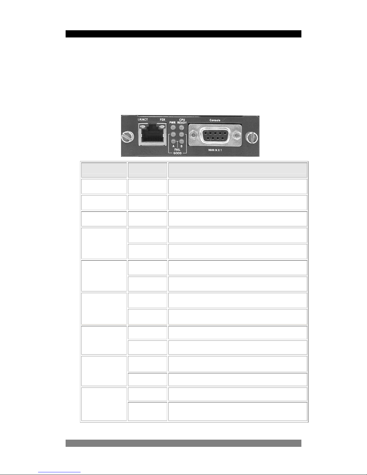
Hardware Description
The Tyco SNMP Managed Converter Chassis is a modular unit that contains 16
converter slots and 2 power slots. The chassis is provided with a plug-in management
card. The RS-232 port is used for local management and the Ethernet RJ-45
connector is for In-band management via Telnet, SNMP or web browser. Both these
physical interfaces are on the front panel of the management card.
Front & Rear Panel
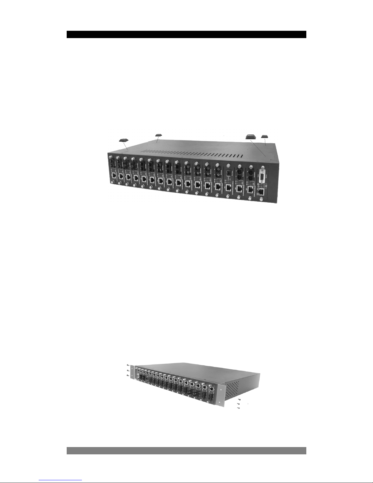
The front panel of the SNMP Managed Converter Chassis is shown below fully
populated with the Management card in the far left hand slot and then 16 plug-in fibre
media converter cards in slots numbered 1…16 towards the right.
Figure 3 – SNMP Managed Media Converter Chassis - Front View
The standard IEC power socket is located at the rear panel of the Tyco SNMP
managed converter chassis. The AC power range is 100-240VAC, 50-60Hz and the
DC power range is 40.5 ~57.0V. Two power supply units of either AC or DC type can
be installed in the chassis. The factory default chassis is supplied with one AC power
module unit and one fan unit.
Power Slot B is installed with
a fan unit by default.
0-1591500-x ©Tyco Electronics 2004 Issue 1.2
Figure 4 –SNMP Managed Media Converter Chassis - Rear View
Power Slot A is fitted with
an AC Power Module
Page 11

Tyco SNMP Managed Media Converters Page 11
0-1591500-x ©Tyco Electronics 2004 Issue 1.2
Installation
Pre-Installation Requirements
Before you start hardware installation, make sure your installation environment has
following items:
• Standard PC with 10/100Mbps Ethernet interface
• S/UTP LAN cables terminated with RJ-45 connectors.
• Fibre cables with the required connector formats (SC/ST/MT-RJ connectors)
• A dedicated AC power source at 100 to 240V AC at 50/60 Hz or 48v DC power.
Ensure that the chassis power is accessible and power cables can be connected
easily.
• A dry cool location. Keep the chassis away from moisture and avoid direct sunlight,
sources of heat and high amount of electromagnetic interference.
• Small cross-head screw driver to remove the chassis blanking panels
• Large screw driver to mount the chassis in a rack.
Cautions:
• All cabling must be routed away from sources of electrical noise such as radio,
computers, transmitters, broadband amplifiers, power lines etc.
• Airflow around the chassis and through its vents on the rear must not be restricted.
DC Power Supply Connections
The optional 48v DC plug-in power unit (Model Number 0-1591506-0) can be fitted into
the chassis. Remove the fan unit from the chassis unit and carefully insert the DC
power unit into the chassis. Secure the power unit with screws. The DC power supply
has a set of screw terminals on the rear of the power unit. Secure the supply leads to
these screw terminals using spade style connections.
• Connect the 0v or negative of the DC supply to the screw marked GND
• Connect the +48v or positive of the DC supply to the screw marked VIN
Ensure that the input DC supply is floating with respect to chassis to avoid ground
loops.
Page 12
Tyco SNMP Managed Media Converters Page 12
Desktop Installation
Set the chassis on a sufficiently large flat space with a power outlet nearby, and near
the centre of all networked devices. Make sure mounting surface on the bottom of the
chassis is grease and dust free. Remove the adhesive backing from the supplied
rubber feet.
Figure 5 – Fitting Rubber Feet
Apply the rubber feet to each corner on the bottom of the chassis. These footpads can
prevent the chassis from shock/vibrations.
Caution: Do not place objects on top of the chassis unit or obstruct the side vents.
Rack-mounted Installation
The SNMP Managed converter chassis is supplied with a rack-mounted kit and can be
mounted in an EIA standard size, 19-inch rack. The chassis can be placed in a wiring
closet with other equipment.
Perform the following steps to rack mount the chassis:
• Position one bracket to align with the holes on one side of the chassis and
secure it with the smaller bracket screws.
• Then attach the remaining bracket to the other side of the chassis.
Figure 6 – Fitted Rack Mounted Ears
0-1591500-x ©Tyco Electronics 2004 Issue 1.2
Page 13

Tyco SNMP Managed Media Converters Page 13
After attaching both mounting brackets, position the chassis in the rack by lining up the
holes in the brackets with the appropriate holes on the rack. Secure the chassis to the
rack with the rack-mounting screws.
Figure 7 – Fitting Chassis into a rack
[Note] For proper ventilation, allow at least 4 inches (10 cm) of clearance on the
front and 3.4 inches (8 cm) on the back of the chassis. This is especially important
for enclosed rack installation.
Applying Power
After all network cables are connected, apply AC or DC power as required to the
SNMP managed chassis. Turn the power on using the power switch on the back panel.
Check the front panel power indicator LEDs on the Management Card to verify that
power is properly supplied. See page 15 for details.
Simple Diagnostic Test
After the installation is completed and the power is applied to the chassis, the system
will automatically perform a diagnostic test.
After boot-up, the CPU Ready LED indicator on the Management Card will toggle on
and off every 3~5 seconds if media converter cards are installed in the chassis.
0-1591500-x ©Tyco Electronics 2004 Issue 1.2
Page 14

Tyco SNMP Managed Media Converters Page 14
0-1591500-x ©Tyco Electronics 2004 Issue 1.2
Quick Start Guide
The steps below are intended to guide the technically competent user through the
initial configuration of the SNMP chassis for both Telnet and Web based management
systems. For full details of these steps, see the relevant sections of the manual.
1. Place the chassis into a safe environment suitable for testing the key functions.
2. Fit at least one media converter card into the chassis and apply power to the
chassis. Ensure that the LED indicators are lit as detailed in the tables on pages 15
and 16.
3. Connect a PC serial console port to the chassis using the supplied RS232 cable as
described in page 18.
4. Start the terminal emulation program on the PC and check that the basic console
menu is displayed as described on page 18.
5. Log into the chassis by using the default user name of root and the default
password of root.
6. Change the IP address details for the chassis by selecting option 1 – Device
Settings menu and then options 4, 5 and 6 to apply the new IP address, subnet
mask and default gateway values. The network administrator should provide these
values.
7. Save these new settings and reboot the switch by selecting S and then R on the
Main menu.
8. Connect the Ethernet LAN port of the Management Card to the network and check
that the chassis responds to “ping requests” directed to the programmed IP
address. See page 45 for further information.
9. Open a Telnet session on the PC and specify the chassis programmed IP address.
The Main menu screen should be displayed.
10. Open a web browser session and specify the chassis IP address. It may be
necessary to apply the browser security settings detailed on page 42 if the browser
does not display the correct image of the populated chassis.
11. Use the Module Settings screen of the browser to select the required media
converter card. Check that the displayed settings match the expected values.
12. Apply the required configuration values to the media converters and chassis unit.
13. Save the new settings using the Save& Reboot menu.
Page 15
Tyco SNMP Managed Media Converters Page 15
LED Indicators
All LED status indicators are located on the front panel of the chassis. These indicators
provide real-time indication of system and operational status.
Management Card LED Indicators
LED Status Meaning
CPU Ready Slow Flash The management card is working correctly
CPU Ready Green
The management card has failed or no
modules are fitted in the chassis
PWR
Green Power on
Green External Power supplied to PSU A
Good A
Off
No External power supplied to PSU A or
PSU A not fitted
Green External Power supplied to PSU B
Good B
Off
No External power supplied to PSU B or
PSU B not fitted
Orange Power unit A has failed
Fail A
Off Power unit A is ready
Orange Power unit B has failed
Fail B
Off Power unit B is ready
Green
Ethernet port is connected to an external
device.
LK/ACT
Flash The port is receiving or transmitting data
Yellow Ethernet link in Full Duplex mode
FDX
Flash Collision of Packets occurs in the port.
Table 2 – Management Card LED Indications
0-1591500-x ©Tyco Electronics 2004 Issue 1.2
Page 16

Tyco SNMP Managed Media Converters Page 16
Media Converter LEDs
10/100Mbits/s Ethernet Media Converter LEDs
LED Status Meaning
Speed (RJ-45)
Green Link operating in 100Mbps mode
Green Ethernet Link connected
LINK/ACT
(RJ-45)
Flash
The port is receiving or transmitting data
on the RJ-45 port.
Orange In Full Duplex mode
Flash
Collision of Packet has occurred on this
port
FDX/COL
(RJ-45)
Off Half Duplex mode
Power
Green Power On
Green Fibre Link connected
LINK/ACT
(Fibre)
Flash
The port is receiving or transmitting data
on the fibre port.
Green Port In Full Duplex mode
Flash
Collision of Packet has occurred on this
port
FDX/COL
(Fibre)
Off Port In Half Duplex mode
Table 3 – Module LED Indications
0-1591500-x ©Tyco Electronics 2004 Issue 1.2
Page 17

Tyco SNMP Managed Media Converters Page 17
Gigabit Ethernet Media Converter LEDs
LED Status Meaning
Green Link in 1000Mbps mode
Orange Link in 100Mbps mode
Speed (RJ-45)
Off Link in 10Mbps mode
Green Ethernet Link connected
LINK/ACT
(RJ-45)
Flash
The port is receiving or transmitting data on
the RJ-45 port.
Orange In Full Duplex mode
FDX (RJ-45)
Off Half Duplex mode
Power
Green Power On
Green Ethernet Link connected
LINK/ACT
(Fibre)
Flash
The port is receiving or transmitting data on
the RJ-45 port.
Green In Full Duplex mode
FDX/COL
(Fibre)
Off In Half Duplex mode
Table 4 – Gigabit Module LED indications
0-1591500-x ©Tyco Electronics 2004 Issue 1.2
Page 18

Tyco SNMP Managed Media Converters Page 18
Detailed Configuration
Using a Local Console to Connect to the Chassis
The console port is a male DB-9 connector located on the front panel of the chassis
management card. This port enables a connection to a PC or terminal for monitoring
and configuration. Use the supplied RS-232 cable with a female DB-9 connector to
connect a terminal or PC to the Console port.
After connection to the Console port, turn on the PC or terminal and configure its
communications parameters to match the following default characteristics of the
console port:
Baud Rate: 9600 bps
Data Bits: 8
Parity: None
Stop Bit: 1
Flow control: None
Figure 8 – Terminal Settings
Logging into the Chassis
Hyper Terminal
TM
or other terminal emulation programs can be used with the above
settings for Console management. After communication has been achieved the user
will be prompted for a login user name and password.
Default login user name: root
Default login password: root
Note: User lower case letters only to enter the default user name and password.
0-1591500-x ©Tyco Electronics 2004 Issue 1.2
Page 19

Tyco SNMP Managed Media Converters Page 19
Main Menu
After the user has logged on they will be prompted to enter “m” to enter the main menu.
The following console style screen is then displayed:-
Figure 9 – Console Main Menu Screen
The Main menu is the top-level menu for the console and Telnet interfaces. The
options are:-
Figure 10 – Console and Telnet Menu Tree
0-1591500-x ©Tyco Electronics 2004 Issue 1.2
Page 20

Tyco SNMP Managed Media Converters Page 20
0-1591500-x ©Tyco Electronics 2004 Issue 1.2
The available Main menu options are:-
No. Menu Item Description
1
Device Settings
Configure and view the settings for the chassis unit
including IP address, password, user interface modes etc.
2
Module Settings
Configure and view the settings for the selected media
converter unit. Settings include enable/disable, speed etc.
3
Redundant
Power Status
View the status of both power supply units.
4
Event Log
Enable and view the event log that displays detected faults
including module plugged out, fibre fail etc.
5
SNMP Trap
Configure the SNMP trap sub-system including trap
addresses and community strings.
6
Secure IP
Configure IP addresses that are permitted to manage the
chassis system over the IP network.
S
Save Current
Settings
Saves all settings of the chassis and media converter cards
into non-volatile memory.
D
Factory Default
Settings &
Reboot System
Selectively restore the factory default conditions to reset all
controls to a the shipped status.
R
Reboot System
Reboots the chassis and media converter modules.
Q
Quit
Exit the Main menu and log off
Table 5- Main Menu Options
After selecting a menu item (from the range 1..6, S,D,R and Q) enter the <CR> or
<Return> key on the PC to activate the item.
Page 21

Tyco SNMP Managed Media Converters Page 21
Managing the Chassis using Console Menus
Device Settings Menu
This menu is used to configure specific top level system values such as the IP Address
information, user and password information, SNMP community strings and system
names etc.
From the Main menu shown in page 19, select option 1 Device Settings and press
<Enter> or carriage return on the PC keyboard. The Device Settings menu is then
displayed as shown below.
Figure 11 – Device Settings Menu
Menu items that have (RO) next to them are read only and cannot be configured or
modified. These are provided for information purposes only.
0-1591500-x ©Tyco Electronics 2004 Issue 1.2
Page 22

Tyco SNMP Managed Media Converters Page 22
0-1591500-x ©Tyco Electronics 2004 Issue 1.2
No. Menu Item Description
1
System Name
A particular name can be assigned to the chassis for
reference purposes. The maximum field length is 64
characters and the default value is “Tyco SNMP
Managed Converter Chassis”.
2
System Location
A description of the location of chassis can be assigned.
The maximum field length is 64 characters.
3
System Contact
A contact name for the chassis can be assigned. The
maximum field length is 64 characters.
4
IP Address
The IP address of the device must be assigned to allow
Tenet or Web management. The default IP address is
192.168.1.1
5
Subnet Mask The default value is 255.255.255.0
6
Default Gateway The default value is 192.168.1.254
7
Change
User/Password
The default username and password is “root”. This can
changed to a different username or password.
8
Get Request
Community
A community string for SNMP “get” requests” can be
assigned. The default value is “Public”.
9
Set Request
Community
A community string for SNMP “set” requests” can be
assigned. The default value is “Public”.
A
HTTP Enable
This allows configuration of the converter chassis
through the Web. The default is Enabled.
B
Telnet Enable
This allows configuration of the converter chassis via
Telnet. The default is Enabled.
Q
Quit
Return to the Main Menu
Table 6 - Device Settings Menu Options
Note
It is very important that after any changes have been made to the IP Address
and other primary chassis settings that the user returns to the main menu,
saves the new settings and reboots the chassis. This is achieved by:-
1. Selecting “Q” to quit the Device Settings menu to return to the Main menu,
2. Selecting “S” to save the settings in the Main menu,
3. Selecting “R” to reboot the chassis.
Page 23

Tyco SNMP Managed Media Converters Page 23
Modules Settings Menu
The media converter modules can be configured using the Module Settings menu
which is selected by entering “2” from Main menu. The first part of the Module Settings
menu is displayed and you are prompted to enter the number of the module for
configuration (1…16) where slot 1 is the first slot to the right of the management card
and slot 16 is the slot at the far right hand side of the chassis. Press “Enter”.
Figure 12 – Module Settings Menu Screen
No. Menu Item Description
1
Module
enable/disable
Enable or disable module function. The default is
“Enable”. If the module is disabled then the module will
not transport any traffic.
2
LLF Direction
When the UTP or Fibre is link down, it will force the
other port to auto disconnect. The forced direction
depends on the setting “UTP controls Fibre port” or
“Fibre controls UTP port” pull-down option. The LLF
default is “Disabled” and other selections are “FX
Control Utp” and “UTP Controls FX”.
3
UTP Speed/ Duplex
Configure the UTP port speed and mode. The default is
“auto”.
4
Fibre Speed/Duplex
Configure Fibre port speed and mode. The default is
“100M” and “Full”.
5
Reset to default
Reset the module configuration to the default value.
6
Note
Enter the short description or note for this module. The
maximum length is 32 characters.
Q
Quit
Return to the Main Menu
Table 7 - Module Settings Menu Options
0-1591500-x ©Tyco Electronics 2004 Issue 1.2
Page 24

Tyco SNMP Managed Media Converters Page 24
Redundant Power Status Menu
The chassis has two slots for plug-in power units. The left hand unit is Power A and
right hand unit is Power B. The chassis power supply status can be viewed by
selecting option 3 from the Main Menu and then the following screen is displayed:-
Figure 13 - Redundant Power Status Display
From the display above it can be seen that both power supplies are fitted and working.
If a power supply is either not fitted or has failed, the power supply will indicate “not ok”
as shown in the example below:-
Figure 14 - Redundant Power Status – Power Unit B is Faulty/Missing
0-1591500-x ©Tyco Electronics 2004 Issue 1.2
Page 25

Tyco SNMP Managed Media Converters Page 25
Event Log Menu
The chassis management card can store up to 4095 event records. By selecting option
4 Event Log from the main menu the following options will be displayed: -
Figure 15 – Event Log
The event log menu options are:-
No. Menu Item Description
1
Event Log Enabled
If the event log is enabled then events that occur such
as link down or link up will be recorded and displayed.
2
Show Event Log If Event Log is enabled (option 1) then all log events
will be displayed as a sequential list.
3
Delete All Event Log
All event log records that stored in system non-volatile
memory will be deleted.
Q
Quit
Return to the Main menu
Note that chassis and card events such as module plugged in/out together with link
up/down will be displayed on the console menu irrespective of the menu level and
irrespective of the enabled state of the Event Log. This real-time display of system
change feature can be very useful when diagnosing network problems or other issues.
0-1591500-x ©Tyco Electronics 2004 Issue 1.2
Page 26

Tyco SNMP Managed Media Converters Page 26
Figure 16 - Example Event Log Display
The above example shows the screen output of the Event Log. Each recorded event
since the Event Log was Enabled is sequentially numbered with the first event
assigned the index of 1. Each event is time-stamped based on the relative time since
the management card/chassis was reset. No real-time clock is implemented in the
chassis. The number of the module (1..16) that detected the event together with type
of event is then displayed. This combination of information can be a great assistance in
detailed fault-finding. To assist in determining the actual time that an event was
detected, it is good practice to note the real time at which the chassis/management
card was reset. Simply add the relative time displayed in the event log to the real time
that the system was reset to obtain the approximate real time of the event.
0-1591500-x ©Tyco Electronics 2004 Issue 1.2
Page 27

Tyco SNMP Managed Media Converters Page 27
SNMP Trap Menu
By selecting menu item 5 from the Main menu “SNMP Trap” then the settings for
SNMP traps be configured and the following screen is displayed.
Figure 17 – SNMP Trap Setup Menu
The SNMP Trap menu options are:-
No. Menu Item Description
1
Send Trap
This command Enables or Disables the SNMP Trap
function.
2
Trap Community
The Trap Management Station must have same
community string as specified in this field. The default
community string is “public”.
3
Trap IP 1
Trap Station 1 IP Address
4
Trap IP 2
Trap Station 2 IP Address
5
Trap IP 3
Trap Station 3 IP Address
6
Trap IP 4
Trap Station 4 IP Address
Q
Quit
Return to the Main menu
Table 8 - SNMP Trap Menu Options
0-1591500-x ©Tyco Electronics 2004 Issue 1.2
Page 28

Tyco SNMP Managed Media Converters Page 28
Secure IP for Telnet, HTTP and SNMP Menu
For security reasons it may be necessary to restrict the remote management of the
SNMP chassis to predetermined management stations. This restriction can be
achieved by only allowing certain IP addresses to remotely manage the chassis. If
menu item 6 is selected from the Main menu then the following screen is displayed: -
Figure 18 – Setting Secure IP menu
The Secure IP Setting menu options are:-
No. Menu Item Description
1
Secure IP for Telnet
This enables or disables the secure IP function for the
Telnet interface.
2
Secure IP for HTTP
This enables or disables the secure IP function for the
Web interface.
3
Secure IP for SNMP
This enables or disables the secure IP function for
SNMP management.
4
Secure IP 1
Assigns the first IP address of the specified station that
can remotely manage the chassis using Telnet, HTTP
and SNMP interfaces.
5
Secure IP 2
Second secure IP station address
6
Secure IP 3
Third secure IP station address
7
Secure IP 4
Fourth secure IP station address
Q
Quit
Return to the Main menu
Table 9 - Secure IP Menu Options
0-1591500-x ©Tyco Electronics 2004 Issue 1.2
Page 29

Tyco SNMP Managed Media Converters Page 29
Save Current Settings Command
After changes have been made to any parameters the new settings will not
automatically be saved to non-volatile memory. If the settings are not saved, then after
a restart the changes will be lost. It is advisable to save settings after any changes
have been made. To save settings from the console Main menu select menu item S
“save current settings”.
Factory Default Settings & Reboot System Command
The chassis and modules have a range of settings that are stored in non-volatile
memory. These variables can be restored to the factory default setting.
To restore the default settings, select Main menu item “D”. The user is then prompted
to restore all Module Settings to default. Chose Y to restore the settings of all the
modules or choose or N to leave the module settings un-changed.
The user is then prompted to restore the IP Settings to default settings. If this is
required, select Y. To leave the IP settings unchanged, select N. The chassis will then
restart and all non-volatile settings other than the exceptions above will be restored to
factory defaults. The prompts are shown below:-
Reboot System Command
The management element of the chassis can also be rebooted without restoring the
factory defaults. By choosing option “R” from the console Main menu, the system will
restart.
0-1591500-x ©Tyco Electronics 2004 Issue 1.2
Page 30

Tyco SNMP Managed Media Converters Page 30
Web-Based Management
The Tyco SNMP Managed Converter Chassis supports an embedded HTML web
interface. It offers advanced management features and allows users to manage the
device from anywhere on the network using a standard browser such as Microsoft
Internet Explorer. The Web-Based Management supports Internet Explorer 5.0 and
later versions. It is based on Java Applets this reduces network bandwidth
consumption, enhances access speed and presents an easy to understand viewing
screen.
System Login
Follow the steps below to log into the chassis:-
1. Start Internet Explorer on the PC or Workstation.
2. In the address field of the browser, enter the http prefix followed by the assigned IP
address of the SNMP managed chassis. Consult your network manager for details.
For example, the factory default IP address of the chassis unit is 192.168.1.1 so
enter
http://192.168.1.1 ) and press “Enter” key of the PC.
3. The following screen should be displayed in the browser:-
Figure 19 – Logon Authentication Window
4. Enter the user name and password. The factory default values are:-
5. User Name = root
6. Password = root
The above values must be entered in lower case letters.
0-1591500-x ©Tyco Electronics 2004 Issue 1.2
Page 31

Tyco SNMP Managed Media Converters Page 31
7. Press <Enter> or Click ”OK” in the authentication box, then the home screen of the
Web-based management appears as shown :-
Figure 20 - Web Management Home Page
The home page displays the configuration of the Tyco SNMP Managed Converter
Chassis. If the text “No Response” appears in all the above fields then the security
settings of the browser need to be changed to allow the browser to run the Java
applets in a secure manner. See page 42 for details.
1. System Name: a particular name can be assigned to the device. (maximum length
is 32 characters). Default value is “Tyco SNMP Managed Converter Chassis”.
2. System Location: a description for the location of device can be assigned
(maximum length is 64 characters).
3. System contact: A contact people of device can be assigned. (Characters
maximum length is 64)
4. System Up Time: The time last since the managed unit was reinitialised. This
value is read only.
5. IP address: the IP address of the device must be assigned to allow Tenet or Web
management. The default IP is 192.168.1.1
6. Subnet mask: The default value is 255.255.255.0
7. Default Gateway: The default value is 192.168.1.254
0-1591500-x ©Tyco Electronics 2004 Issue 1.2
Page 32

Tyco SNMP Managed Media Converters Page 32
8. MAC Address: The MAC address of the managed unit. This value is read only.
9. Console: This displays the serial interface settings of the console port.
10. Redundant Power status: Displays the redundant power status.
11. Firmware Version: The firmware version of the management unit. This value is
read only.
Note By default, IE4.0 does not allow Java Applets to open sockets. The user has to
explicitly modify the browser setting to enable Java Applets to use network ports. Later
version browsers do not have this issue.
Modules Settings Menu
The module settings menu shows the settings and status of all installed modules in the
SNMP Managed Converter Chassis. The Module Settings menu has 4 main fields that
can be configured – Module, UTP Port, Fibre Port and Notes. This menu screen will
not automatically refresh, therefore when a module is installed or removed a manual
refresh of the web page will be required. This refresh can be done by licking on the
image of a card in the graphic display at the top of the screen. There may be a delay of
a few seconds between the change of state of a card and the change being displayed.
Figure 21 - Module Settings Menu
0-1591500-x ©Tyco Electronics 2004 Issue 1.2
Page 33

Tyco SNMP Managed Media Converters Page 33
0-1591500-x ©Tyco Electronics 2004 Issue 1.2
Module Controls
The controls and values for the module are in the left hand column of the Module
Settings web page. The available values are:-
State
This value displays the module current status. The module can be
Enabled or Disabled using the pull down control. When the
module is disabled, the card will not respond to copper link pulses
but fibre link continuity is retained. The default value is Enabled.
Mode
This shows the module mode and displays the fibre and connector
type that is automatically detected by the chassis when a module
is installed (Read Only)
LLF Direction
When the UTP or Fibre link is “down”, the media converter can be
configured to force the other port to auto-disconnect. This mode is
called Link Loss Forwarding. The forced direction depends on the
setting of the pull-down control where UTP controls Fibre port or
Fibre controls UTP port. The LLF default is Disabled
Default
To set the configuration to a known default condition, click in this
box.
UTP (RJ-45) Port Controls
The controls and values for the UTP/STP RJ-45 Port of the media converter card are in
the second from left hand column of the Module Settings web page. The available
values are:-
Link
This read-only value shows the current link status of the RJ-45
port. The displayed value Up means it is connected to another
Ethernet 10/100Base-T device and Down means that it is not
linked.
Nego
This pull-down control selects the negotiation mode of the copper
RJ-45 port. Auto means the card automatically negotiates the
speed and duplex mode of the module RJ-45 port with the
attached device. Force means the user can select the speed and
duplex mode. The default is Auto.
Speed
This control allows the user to select the speed of the RJ-45 port to
either 10Mbps or 100Mbps. If the Nego control is set for Force
then the speed of 10Mbps or 100Mbps can be selected using the
Speed pull-down control.
Duplex
This allows the user to select Duplex mode of the copper RJ-45
port. If the “Nego” control is set to Force then the duplex mode
can be set for either Half or Full duplex using the Duplex
pull-down control.
Page 34

Tyco SNMP Managed Media Converters Page 34
0-1591500-x ©Tyco Electronics 2004 Issue 1.2
Fibre Port Controls
The controls and values for the Fibre Port of the media converter card are in the
second from right hand column of the Module Settings web page. The available values
are:-
Link
This read-only value shows the current link status of the fibre port.
Up means that the fibre optic link it is connected to another fibre
device and the link is operational. Down means that the fibre port
is not working correctly or that there is a problem with one of the
fibres.
Nego
This pull-down control allows selection of the fibre link negotiation
mode. The 100Mb/s FX fibre module only has Force mode. The
Gigabit fibre card has Auto and Force modes.
Speed
The select the speed of port fibre port can be selected using the
pull down control. (Gigabit module only)
Duplex
The Duplex mode of the fibre port can be selected using the
pull-down control. The Gigabit fibre converter only works in full
duplex mode. The 100Mb/s Fibre module can be configured to
work in either Full or Half duplex. The default is Full Duplex
Notes Field
In some installations it can be beneficial to assign some text to the card such as link
number to assist in maintenance and faultfinding. A free-format notes field is in the
right hand column of the Module Settings page. A maximum of 32 characters can be
entered into this field.
Apply Settings
After any modifications have been completed click the
Apply
button at the end of the
Module Settings web page to apply the new settings.
Save Configuration Settings
To save the module settings into the Management Card non-volatile memory, use the
Save and Reboot
menu as detailed in page 40.
Page 35

Tyco SNMP Managed Media Converters Page 35
Port Counters Screen
This screen displays information about the number and condition of Ethernet packets
or frames flowing through each of the media converters.
Figure 22 - Port Counters Menu Screen
The displayed read-only values are grouped into two classes depending on the media
converter interface type:-
• (U) shows the performance of the traffic flowing through the UTP/STP RJ-45
port of the converter in the chassis,
• (F) shows the performance of the traffic flowing through the fibre interface of
the converter in the chassis.
Rx Good Pkts
The amount of good packets that have been received on the port
Rx Bad Pkts
The amount of bad or errored packets that have been received on
a port
Tx Good Pkts
The amount of good packets that have been transmitted by a port
Tx Bad Pkts
The amount of bad or errored packets that have been transmitted
by a port
Tx Collision
The amount of transmit collisions detected on a port
Rx Collision
The amount of receive collisions detected on a port
The counters periodically refresh with the latest values displayed. The counters can all
be
Reset
be clicking the Reset button at the bottom of the screen.
Note that the counter refresh rate is partly dependant on the number of media
converters installed in the chassis.
0-1591500-x ©Tyco Electronics 2004 Issue 1.2
Page 36

Tyco SNMP Managed Media Converters Page 36
IP Config Menu
The IP Config menu allows a user to modify the IP address, subnet mask, default
gateway, login username and password. This menu allows critical information to be
changed and so changes must be made with great care to ensure that management
access to the chassis is retained.
Change The IP Address Values
To change the IP Address, first ensure that the correct values are obtained form the
Network Administrator and then use the following steps:-
1. Enter the required IP Address in the IP Address field
2. Enter the required Sub-Net Mask in the Subnet Mask field
3. Enter the required Gateway Address in the Default Gateway field
4. Click the
Apply
button to activate the changes.
Change User And/Or Password
To change the user name or password use the following steps:-
1. Click the Change Password checkbox
2. Enter the required user name in the Username field. The default is root
3. Enter the new password in the Password field, the default is root
4. For security purposes, re-enter the password in the Confirm Password field
5. Click the
Apply
button to activate the changes.
Save Configuration Settings
To save the new settings into the Management Card non-volatile memory, use the
Save and Reboot
menu as detailed in page 40.
Figure 23 - IP Configuration Menu
0-1591500-x ©Tyco Electronics 2004 Issue 1.2
Page 37

Tyco SNMP Managed Media Converters Page 37
SNMP Configuration Menu
The SNMP menu enables the configuration of generic information including the system
name, location and contact.
In addition, the SNMP variables “get” request, "set” request and “Trap” community
name can be configured together with assigning the IP addresses of up to 4 Trap
stations.
The default value of a “get” request community and “trap” community is “
public
”. The
default value of set request community is “
private
”. These parameters must be set
correctly to perform SNMP management of the chassis unit. Click the
“Apply”
button
to activate the new settings.
Up to 4 Trap management stations can be configured to receive the trap packets from
the SNMP managed chassis. Select the “
Send traps to the following management
stations
” check-box and fill in the IP address management stations that require the
SNMP traps. Click the
“Apply”
button to apply the configuration.
Figure 24 - SNMP Configuration Menu
Save Configuration Settings
To save the new SNMP settings into the Management Card non-volatile memory, use
the
Save and Reboot
menu as detailed in page 40.
0-1591500-x ©Tyco Electronics 2004 Issue 1.2
Page 38

Tyco SNMP Managed Media Converters Page 38
Event Log Screen
The event log provides information about events that have been detected by the
chassis and installed media converters.
To enable the event log function and view the logged events, click the
Enable
button
which will change state to show Disable. Then, click the
Refresh
button to update the
event log. The screen will not automatically refresh as a manual refresh is required
view the newest events. To clear all event logs in the display frame, click the
Clear All
button.
Figure 25 - Event Log Display Screen
The log displays an index value that is an incrementing number assigned to each
event. The time of the vent is displayed as the time since the chassis was rebooted.
There is no real-time clock in the chassis.
0-1591500-x ©Tyco Electronics 2004 Issue 1.2
Page 39

Tyco SNMP Managed Media Converters Page 39
Misc Settings Screen
This screen allows a user to enable or disable Telnet management support. This may
be required for network management security purposes. The default value is to have
the Telnet enabled. Select the required mode from the pull-down control.
Figure 26 - Miscellaneous Settings Screen
0-1591500-x ©Tyco Electronics 2004 Issue 1.2
Page 40

Tyco SNMP Managed Media Converters Page 40
Save and Reboot Menu
This menu enables the user to save the chassis and module settings to non-volatile
memory, to restore factory defaults and to reboot the chassis.
Figure 27 - Save and Reboot Menu
Save Current Settings
After configuration changes have been made to any values in the chassis or media
converters, these settings need to be saved to non-volatile memory. If the settings are
not saved then after a chassis restart the changes will be lost. It is strongly advisable to
save settings after any changes have been made. To save the current settings, select
the Save Current Settings checkbox and then click the Apply button located at the
end of the Save Current Settings line.
Factory Default Settings & Reboot
It is possible to restore the system to the factory default settings. This is sometimes
used to regain control of a mis-configured system. Click the Factory Default Settings
& Reboot checkbox. Then decide the scope of the restoration. It is also possible to
selectively restore the media converter module factory default settings and also the IP
address of the management card. Click the box next to the relevant field to restore
these values to factory default conditions. Click the Apply button.
0-1591500-x ©Tyco Electronics 2004 Issue 1.2
Page 41

Tyco SNMP Managed Media Converters Page 41
Reboot System
The management element of the chassis can also be rebooted without restoring the
factory defaults. Select the check box adjacent to the
Reboot system
field and click
the associated
Apply
button to reboot the system. The reboot will take about 15
seconds.
Upgrade Firmware Menu
On occasions it may be necessary to upgrade the Tyco SNMP media converter
chassis firmware to rectify known problems or to add enhancements. This upgrade can
be only done via using the web interface. Upgrade the firmware as described below:-
1. Download the new version of firmware from the Tyco web site at
www.lan-electronics.com and store the file locally on the PC.
2. Enter the user password in the Password box. The default password is root.
3. Enter the file name and path of the file saved in step 1. Alternatively click
browse button to browse for this file.
4. Select the Upgrade button to start the upgrade.
5. The software will be upgraded and the chassis will restart.
6. The new software version will be visible on the web browser home page.
Figure 28 – Upgrade Firmware Menu
0-1591500-x ©Tyco Electronics 2004 Issue 1.2
Page 42

Tyco SNMP Managed Media Converters Page 42
Web Browser Java Settings
In some instances, the web browser may need to have the Java settings modified to
enable the chassis to be configured and controlled using Java Applets. This
modification of the browser settings is required if the web home page shows the
chassis without any modules fitted, even though there were modules in place, or if the
text “No response” is displayed on the main page.
These changes of browser settings have no impact on the SNMP, Telnet or console
interfaces. The changes are described for the Internet Explorer Browser V6 are
described below:-
1. Select the Tools > Internet Options > Security Settings tab
2. Select Local Intranet Zone
Figure 29 - Internet Options Menu Tab
3. Select Custom Level and a new screen is displayed
0-1591500-x ©Tyco Electronics 2004 Issue 1.2
Page 43

Tyco SNMP Managed Media Converters Page 43
4. Scroll down the list to locate the Microsoft VM > Java Permissions and select
the Custom radio button
Figure 30 - Security Settings Menu
5. Then select the Java Custom Settings button and a new screen is displayed:-
0-1591500-x ©Tyco Electronics 2004 Issue 1.2
Page 44

Tyco SNMP Managed Media Converters Page 44
Figure 31 - Internet Settings Menu – Edit Permissions Tab Location
6. Select the Edit Permissions tab and the new menu is displayed:-
0-1591500-x ©Tyco Electronics 2004 Issue 1.2
Page 45

Tyco SNMP Managed Media Converters Page 45
Figure 32 - Internet Settings Menu – Edit Permissions
7. Select the Unsigned Content > Run Unsigned Content and select the radio
button “Run In Sandbox”
8. Then locate the control Additional Unsigned Permissions > Access to all
Network Addresses and select the Enable radio button. Select OK
Additional Notes
In some instances, it may be found necessary to add the IP address of the chassis to
the Trusted Sites list. From the security option in internet options screen choose
“Trusted Sites” option.
Insert the IP address into the trusted sites list. An * can be used to denote a group of IP
addresses. (see
Figure 33 and Figure 34)
0-1591500-x ©Tyco Electronics 2004 Issue 1.2
Page 46

Tyco SNMP Managed Media Converters Page 46
Figure 33 - Internet Settings Menu – Security settings
Figure 34 - Security Settings – Trusted Sites
0-1591500-x ©Tyco Electronics 2004 Issue 1.2
Page 47

Tyco SNMP Managed Media Converters Page 47
0-1591500-x ©Tyco Electronics 2004 Issue 1.2
Frequently Asked Questions
1. When I log into the chassis using a web browser, I cannot see any cards plugged in
and the text “No Response” is displayed.
This is caused by the PC not having the correct settings to run the Java applets
generated by the chassis management card. Apply the browser settings described
on page 42.
2. The web browser fails to find the SNMP chassis.
Ensure that the IP address of the chassis is correct and the right value entered into
the address field of the browser in the form
http://192.168.1.1 but with your IP
address applied. The IP integrity of the chassis can be tested by “pinging” the IP
address of the chassis from the PC. The ping test is accessed on PC platforms by
selecting Start on the Windows toolbar, then selecting Run. Now enter the TCP/IP
ping command using the syntax ping 192.168.1.1 where the IP address is
replaced with the address allocated to your chassis. A black DOS box should be
displayed showing a successful ping and the time taken to transmit data and
receive the response. If “Request Timed out” is displayed then communication has
failed and the network card, cables and IP address settings should be checked.
Ensure that the SNMP chassis and PC are in the same IP subnet for this test.
3. The IP Address setting on the chassis was set but then lost following a restart.
This is caused by the IP address settings not being saved correctly and the chassis
rebooted. Ensure that the steps on page 22 are followed.
4. The Management Card CPU LED is permanently off.
The cause could be either a management card fault or no media converter cards
are fitted in the chassis. If media converter cards are fitted in the chassis and the
CPU Ready LED remains permanently off or on, then the management card has
probably failed. Replace the plug-in management card.
Page 48

Tyco SNMP Managed Media Converters Page 48
0-1591500-x ©Tyco Electronics 2004 Issue 1.2
5. Can I manage distant end media converters from the chassis ?
No, the chassis fully manages the local end media converters. Indirect information
about the state of the distant end media converters is presented as part of the
status reports of the local converters. For example, if there is a power failure at the
remote site, then the optical link will fail and this will be seen as a local Fibre Port
Link Down. If the distant end units need to be SNMP managed, then a different
solution is required. Consult factory for information.
6. Are the power supplies hot-swappable ?
Yes, the supplies can be swapped at any time.
7. Can DC and AC power supplies be mixed in the same chassis ?
Yes, the supplies can be mixed so that AC and DC units can be fitted in the
chassis.
8. Can I replace the Management card ?
Yes, the card can be swapped at any time and it will only fit into the far left hand slot
of the chassis. Note that the management card stores all the settings for the plug-in
media converter cards. This means that when a management card is exchanged,
all the settings for the plug-in media cards and the management card need to be
manually restored before the chassis can re-enter normal service.
9. Can the Management card and media converter card settings be saved to a file
that can be externally saved ?
There is no method of saving the configuration settings to an external file. All
settings are stored in the non-volatile memory of the management card and cannot
be externally accessed.
Page 49

Tyco SNMP Managed Media Converters Page 49
0-1591500-x ©Tyco Electronics 2004 Issue 1.2
Product Specifications
Standards
IEEE802.3 10BASE-T
IEEE802.3u 100BASE-TX and 100BASE-FX with
N-way auto negotiation
IEEE802.3ab Gigabit copper with N-way
auto-negotiation
IEEE802.3z for Gigabit fibre
Max Forwarding Rate
14,880 pps per Ethernet port
148,800 pps per Fast Ethernet port
1488,000 pps per Gigabit Ethernet port
Transparent packet
64 to 1518 Bytes for Non-VLAN Ethernet packet
68 to 1522 Bytes for VLAN-Tag type Ethernet packet
LED Indicators
Management Module: CPU Ready, Power Good (A,
B) Power Fail (A, B), TX (link/Act, FDX)
100FX Module: Power, TX (Link /Act, speed, FDX),
FX (Link /Act, FDX)
Gigabit Module: Power, Gigabit Copper (SPD,
LK/ACT, FDX), Fibre (Link/Act, FDX)
Fibre parameters Fibre Types:
Multi-Mode (62.5/125um, 50/125um)
Single-Mode (8/125um, 10/125um)
Operating Wavelength:
100Mbps multi-mode: 1310nm
100Mbps single-mode: 1310nm
100Mbps WDM 1550 card: TX 1550nm, RX 1310 nm
100Mbps Fibre Distance:
Single-Mode Fibre (30 Km) / Multi-Mode (2Km)
WDM (Single-Mode): 20Km
Gigabit Fibre Distance:
SX (Multi-mode) 500 Metres
LX (Single mode) 10 Km
Optical Characteristics:
100Mbps Multi-Mode: TX (–19dBm), RX (-31dBm),
Power Budget (12dBm)
100Mbps Single-mode (30KM): TX (–15 dBm), RX
(-34 dBm), Power Budget (19dBm)
Gigabit SX Transceiver: TX (–9.5dBm), RX (12.5
dBm), Power Budget (3dBm)
Gigabit LX Transceiver: TX (–9.5dBm), RX (-20 dBm),
Power Budget (10.5dBm)
Dimensions
448mmx 279mm x 89mm (L x W x H)
Operational
Temperature
0C to 45C (32F to 113F)
Page 50

Tyco SNMP Managed Media Converters Page 50
0-1591500-x ©Tyco Electronics 2004 Issue 1.2
Power Supply
Redundant and Load Sharing function support (AC or
DC)
AC 90~240 VAC, 50/60 HZ @ 20A (max)
DC - 40.5 ~ - 57.0VDC @ 20A (max)
EMI
FCC Class A, CE Mark
Safety
cUL, UL
Table 10 – Product Specifications
For order codes of Chassis and converters Please see below
Order Codes
• 10/100M Multimode SC Media Converter
0-1591514-0
• 10/100M Multimode ST Media Converter
0-1591516-0
• 10/100M Multimode MT-RJ Media Converter
0-1591518-0
• 10/100M Singlemode SC Media Converter
• 10/100M Singlemode SC WDM 1550nm Converter
0-1591520-0
0-1591522-0
• Gigabit Multimode SX SC Media Converter
0-1591510-0
• Gigabit Singlemode LX SC Media Converter
0-1591512-0
• 16 Slot SNMP Managed Converter Chassis (AC
power)
• Spare/Redundant AC Power Unit
• Spare/Redundant DC Power Unit
0-1591500-x
0-1591504-0
0-1591506-0
Where –x is the country code. –1 = US and Canada, -2 = Europe, -7 = UK
Table 11 – Product Order Codes
 Loading...