

Page 1

24 Port Stackable Managed Switch – User Guide Page 1
24 Port Stackable Managed Switch
With Dual Port Expansion Slot
Product User Guide
Product Number 0-1591099-x © Tyco Electronics 2005 Issue 1
Page 2

24 Port Stackable Managed Switch – User Guide Page 2
Disclaimer
Tyco Electronics makes no representation or warranties with respect to the contents hereof
and specifically disclaims any implied warranties or merchantability or fitness for any
particular purpose. Further, Tyco Electronics reserves the right to revise this publication and
make changes from time-to-time in the content hereof without obligation of Tyco Electronics to
notify any person of such revision or changes.
Features
• Conforms to IEEE802.3, 802.3u, 802.3z, 802.3ab, 802.3ad, 802.3x, 802.1p, 802.1d,
802.1w and 802.1q. 802.1x
• Single IP stack management
• 24 auto-sensing 10/100Mbps Ethernet RJ-45 port s
• 1 Expansion slot for optional modules:
o 100Fx SC Multimode Fibre
o 100Fx ST Multimode Fibre
o 100Fx SC Singlemode Fibre
o Dual Gigabit Multimode Sx
o Dual Gigabit Singlemode Lx
o Dual Gigabit Copper 1000BaseT
• Store - And - Forward switch architecture
• 8K-entry MAC address table
• Up to 256 Sta t ic and 2048 dynamic VLAN groups.
• IGMP snooping supporting 256 groups.
• 8 MB system memory
• 8.8 Gbps Backplane Bandwidth
• Full wire speed forwarding rate
• LED-indicators for Power, Link/Activity, FDX/COL
• 10/100/1000M Gigabit Module LNK/ACT, FDX/ COL status
Intelligent Management Features
• Console and Telnet Configuration
• Web based management
• SNMP network management
• Asymmetrical bandwidth limiting and control on each port
• Port based VLANS
• Protocol VLANS
• Tagged VLANS using IEEE802.1Q
• Programmable QoS
• Port Trunking
• Spanning Tree Protocol (802.1d and 802.1w)
• GVRP/IGMP protocol
• Port mirroring
• Radius Authentication
• TFTP support for firmware downloads, configuration backup and restore
Product Number 0-1591099-x © Tyco Electronics 2005 Issue 1
Page 3

24 Port Stackable Managed Switch – User Guide Page 3
Technical Support and Service
If you require technical advice for these products, please see the
FAQ pages on the web address: -
http://www.tycoelectronics.com/products/lanelectronics
If you still have problems, please contact us using the support
form located on the above web site.
If you have a faulty unit then please contact us through the web
site to arrange for a replacement unit. The faulty unit must be
returned to us as part of the replacement agreement.
Product Number 0-1591099-x © Tyco Electronics 2005 Issue 1
Page 4
24 Port Stackable Managed Switch – User Guide Page 4
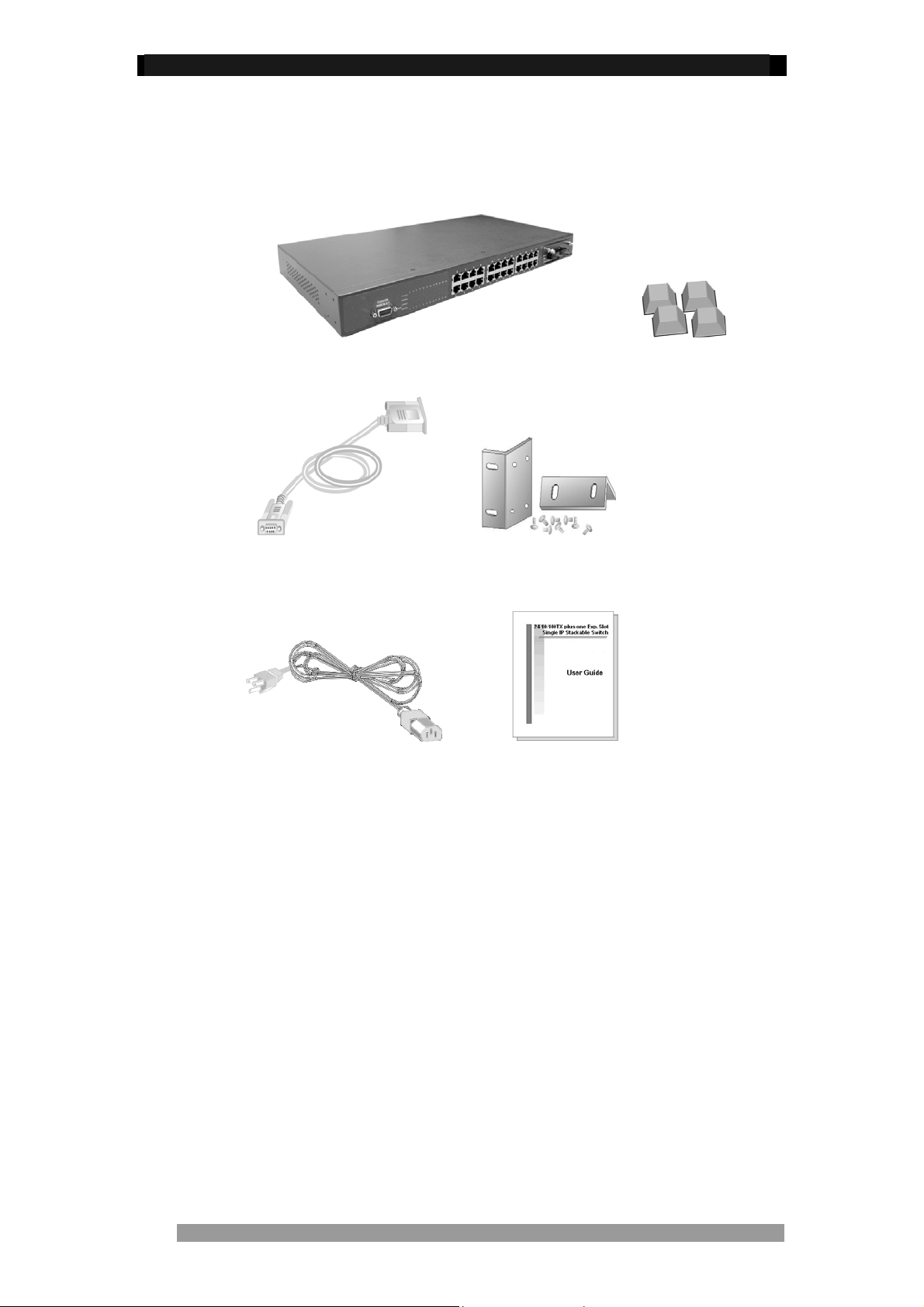
Package Contents
Unpack the contents of the 24 Stackable Managed Switch and verify them against the
checklist below.
24 Port Stackable Ma naged Switch Four Rubber Feet
RS-232 Cable Rack-mounted Kit
Power Cord User Guide
Figure 1. Package Contents
Compare the contents of the 24 Port Stackable Managed Switch with the standard checklist
above. If any item is missing or damaged, please contact your local dealer for service.
Product Number 0-1591099-x © Tyco Electronics 2005 Issue 1
Page 5

24 Port Stackable Managed Switch – User Guide Page 5
The 24 Port Stackable Managed Switch supports the following management methods:
• Console and Telnet Management
• Web-based Management
• SNMP Network Management
Console and Telnet Management
Console Management is performed through the RS-232 Console Port. Managing the 24
Stackable Managed Switch using this method requires a direct connection between a PC and
the 24 Port Stackable Managed Switch. Telnet allows remote management of the Switch
across the network. Once the 24 Port Stackable Managed Switch is on the network with an
assigned IP address, it is possible to use Telnet to log in and change the configuration.
Web Based Management
The Switch can be managed using a standard web browser that supports Java applets. This
interface has the same functionality as the console/Telnet interfaces but is more user-friendly.
See page 42 for details.
SNMP Network Management
SNMP (Simple Network Management Protocol) provides a means to monitor and control the
Switch. Agents, which reside in the Switch, respond to requests from the NMS (Network
Management Station). The agent returns information contained in a MIB (Management
Information Base), which is a data structure that defines what is obtainable from the Switch
and what can be controlled.
Product Number 0-1591099-x © Tyco Electronics 2005 Issue 1
Page 6
24 Port Stackable Managed Switch – User Guide Page 6
Hardware Description
The 24 Stackable Managed Switch has fixed 24-port auto-sensing Ethernet RJ-45
connectors, and one expansion slot that can support a range of optional modules. These
optional modules enable the Switch to support Gigabit copper and fibre optic circuits.
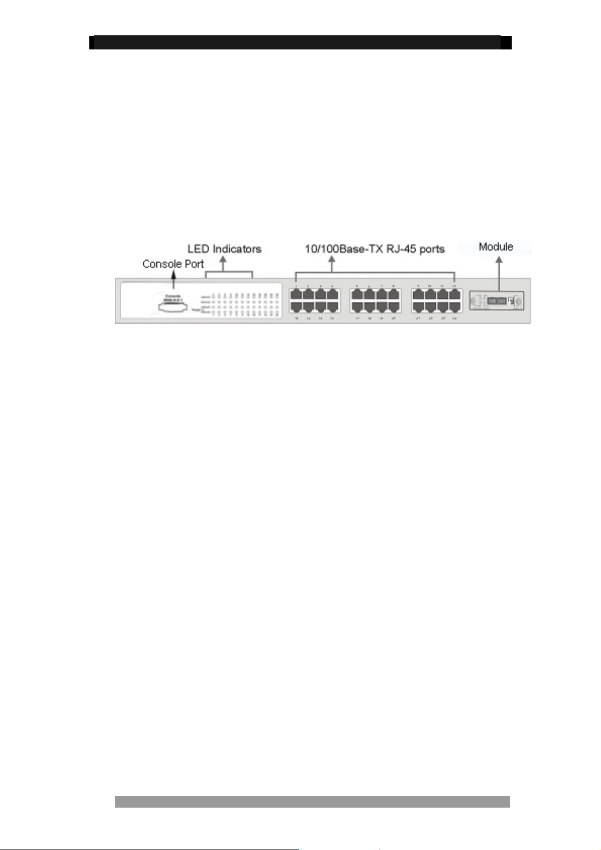
Front Panel
The Front Panel of the Switch consists of 24 auto-sensing 10/100Mbs Ethernet ports, one
optional expansion slot and a console port. The LED Indicators are also located on the front
panel of the Switch.
Figure2. The Front panel of 24 Port Stackable Managed Switch
10/100Base-TX Auto MDI/MDIX RJ-45 Ports
The 24 10/100Mbps auto-sensing ports can support 10Base-T or 100Base-TX device
connection. The auto-MDI/MDIX function enables the direct connection to another Switch or
workstation without the need to select either a straight or cross-over cable.
Expansion Slot
The Switch can support one of the following expansion modules:
• Single 100Fx SC Multimode Fibre
• Single 100Fx ST Multimode Fibre
• Single 100Fx SC Singlemode Fibre
• Dual Gigabit Multimode Sx
• Dual Gigabit Singlemode Lx
• Dual Gigabit Copper 1000BaseT
Console Port
The Switch can be fully managed using the console port connected to a PC using the
supplied RS-232 cable.
Product Number 0-1591099-x © Tyco Electronics 2005 Issue 1
Page 7
24 Port Stackable Managed Switch – User Guide Page 7
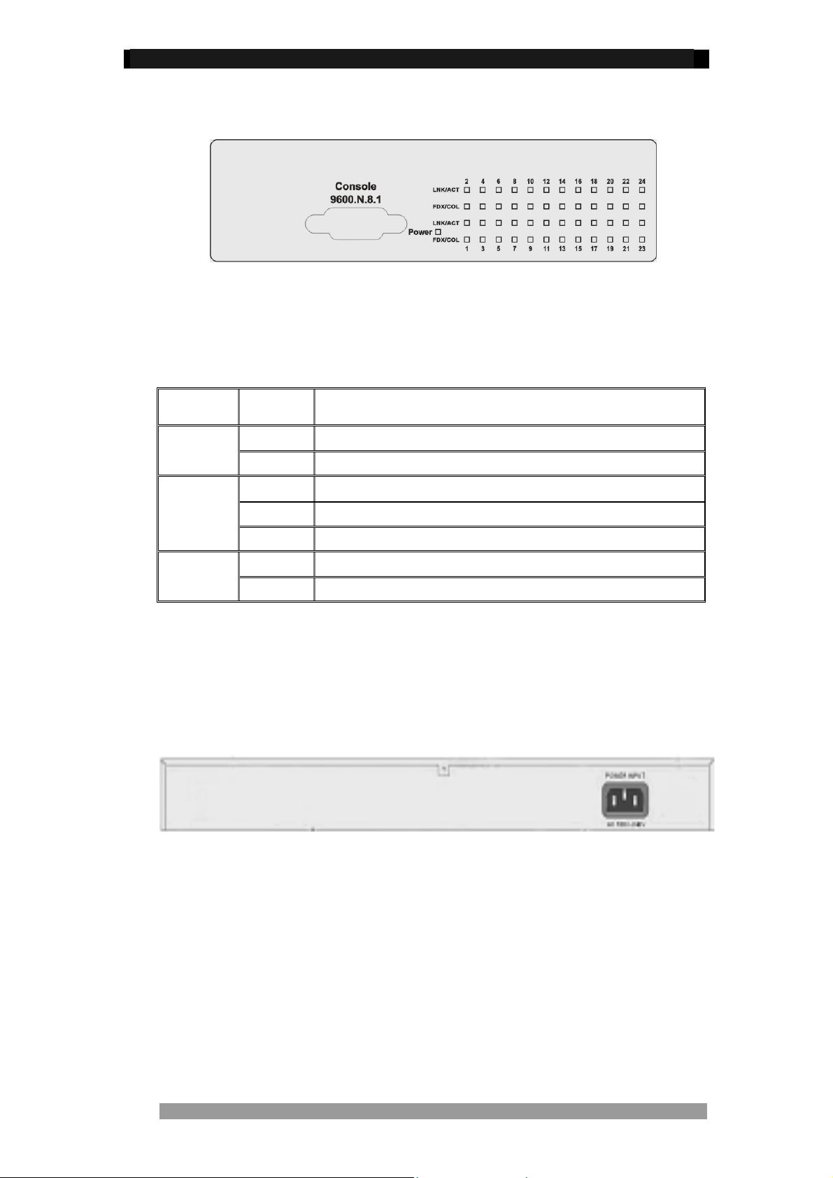
LED Indicators
Figure3. LED indicators
All LED indicators are located on the front panel of the 24 Port Stackable Managed Switch
and provide a real-time indication of Switch condition and operational status. The following
table details the LED states:
LED Status Description
Power
LNK/ACT
FDX/COL
Green Power On
Off Power is Off.
Green The port is connected to an Ethernet device.
Blinks The port is receiving or transmitting data
Off No device is attached
Orange The port is operating in Full-duplex mode
Blinks Collisions are occurring on the port (Half-duplex only)
Table 1. Descriptions of LED Indicators
Rear Panel
The 3-pronged power socket is located at the rear panel of the Switch. The Switch operates in
a range between 100-240V AC, 50-60Hz without adjustment
.
Figure 4. The Rear Panel of the 24 Port Stackable Managed Switch
Product Number 0-1591099-x © Tyco Electronics 2005 Issue 1
Page 8
24 Port Stackable Managed Switch – User Guide Page 8
Installation
Pre-Installation Requirements
Before starting the hardware installation, make sure the installation environment has the
below items:
• PC with 10/100Mbps RJ-45 Network Interface Card to connect the Switch’s copper
port.
• UTP/STP cable with RJ45 connectors. Ensure that the cable has been tested
• AC Power: 100 to 240V AC at 50/60 Hz: Make sure that the power is accessible
and the AC power can be connected easily.
• Dedicated power supply: Use a dedicated AC supply to power the Switch.
• A dry cool place: Keep the Switch away from moisture. Avoid direct sunlight,
sources of heat, and a high amount of electromagnetic interference.
• Mounting tools: If you intend to mount the Switch in a rack, make sure you have all
the tools, mounting brackets, screws etc
Caution:
Cabling must be away from sources of electrical noise such as radio, computers, transmitters,
broadband amplifiers, power lines etc.
Mounting the Switch
The 24 Port Stackable Managed Switch is suitable for use in an office environment where it
can be rack-mounted in standard EIA 19-inch racks or Desktop.
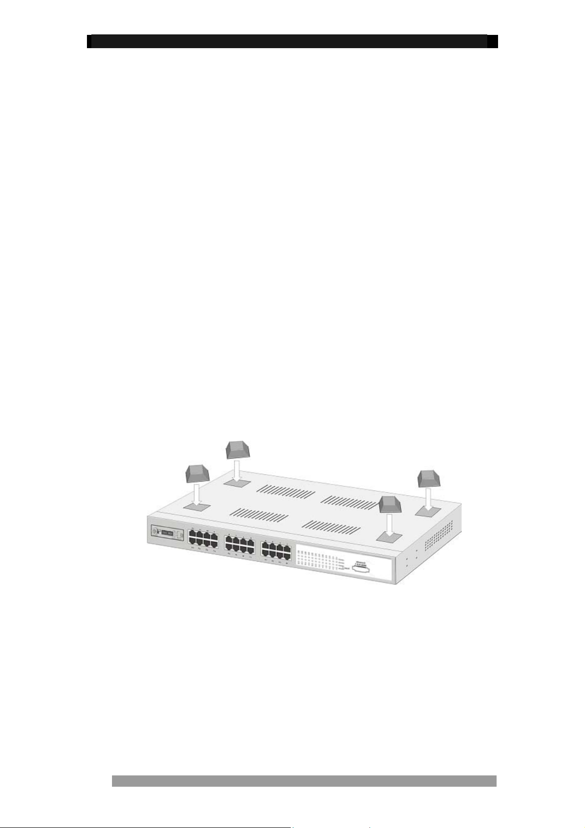
Desktop Mounting
Set the Switch on a sufficiently large flat space with a power outlet nearby, and near the
center of all networked devices. Make sure mounting surface on the bottom of the Switch is
grease and dust free. Remove adhesive backing from the Rubber Feet.
Figure 5. Attach Rubber Feet to each corner on the bottom of the Switch
Apply the Rubber Feet to each corner, on the bottom, of the Switch. These footpads can
prevent the Switch from shock/vibrations.
Caution: Do not place objects on top of the Switch
Product Number 0-1591099-x © Tyco Electronics 2005 Issue 1
Page 9
24 Port Stackable Managed Switch – User Guide Page 9
Rack-mounted Installation
The 24 Port Stackable Managed Switch is supplied with a rack-mounted kit and can be
mounted in an EIA standard size, 19-inch rack. The Switch can be placed in a wiring closet
with other equipment.
Perform the following steps to ra ck mount the Switch:
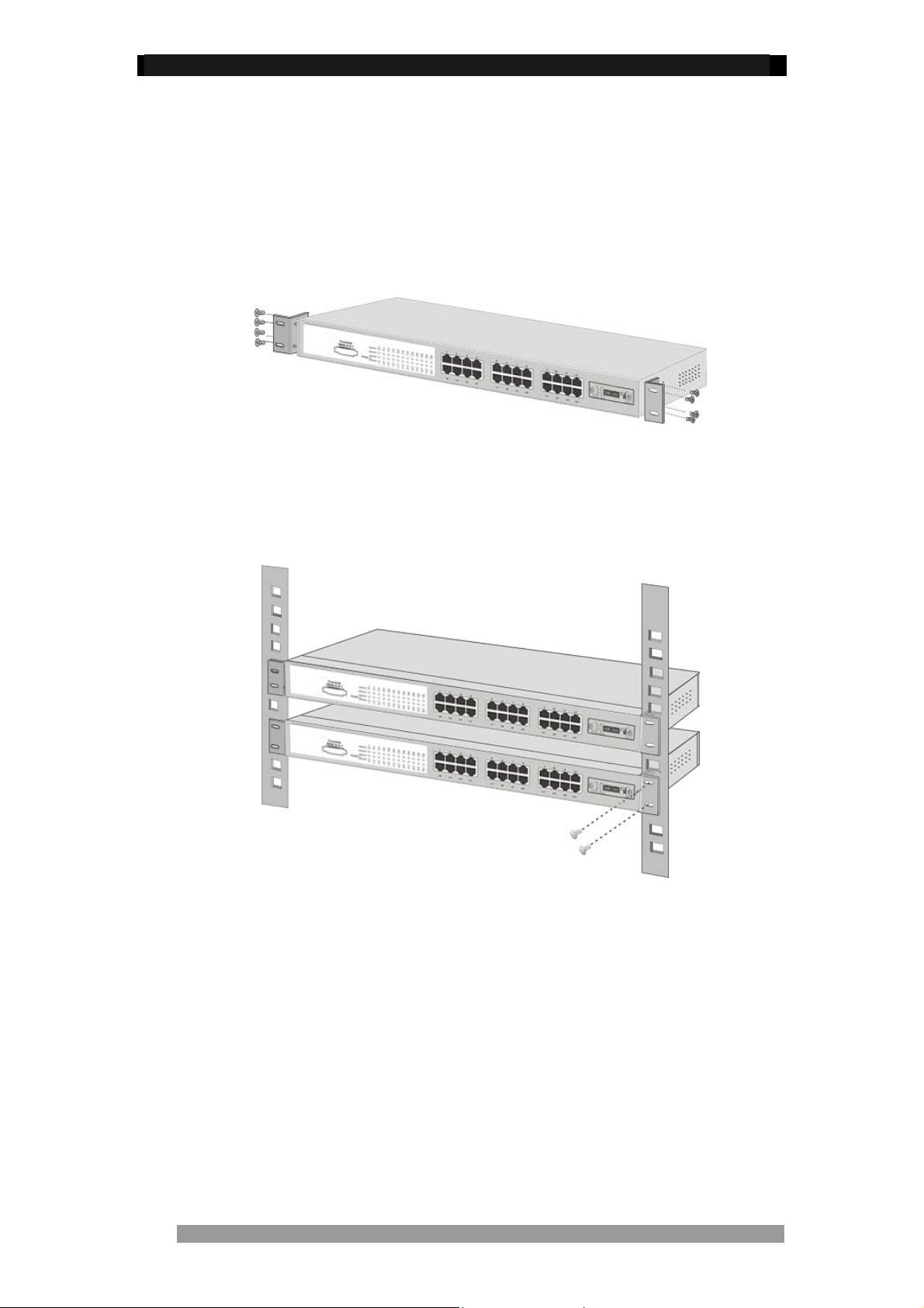
Position one bracket to align with the holes on one side of the Switch and secure it with the
smaller bracket screws. Then attach the remaining bracket to the other side of the Switch.
Figure 6. Attach mounting brackets with screws
After attaching both mounting brackets, position the Switch in the rack by lining up the holes
in the brackets with the appropriate holes on the rack. Secure the Switch to the rack with the
rack-mounting screws.
Figure 7. Mount the Switch in an EIA standard 19-inch Rack
NOTE: For ventilation allow at least 4 inches (10 cm) of clearance on the front and
3.4 inches (8 cm) on the back of the Switch. This is especially important for enclosed
rack installation.
Product Number 0-1591099-x © Tyco Electronics 2005 Issue 1
Page 10
24 Port Stackable Managed Switch – User Guide Page 10
Connecting to the Switch
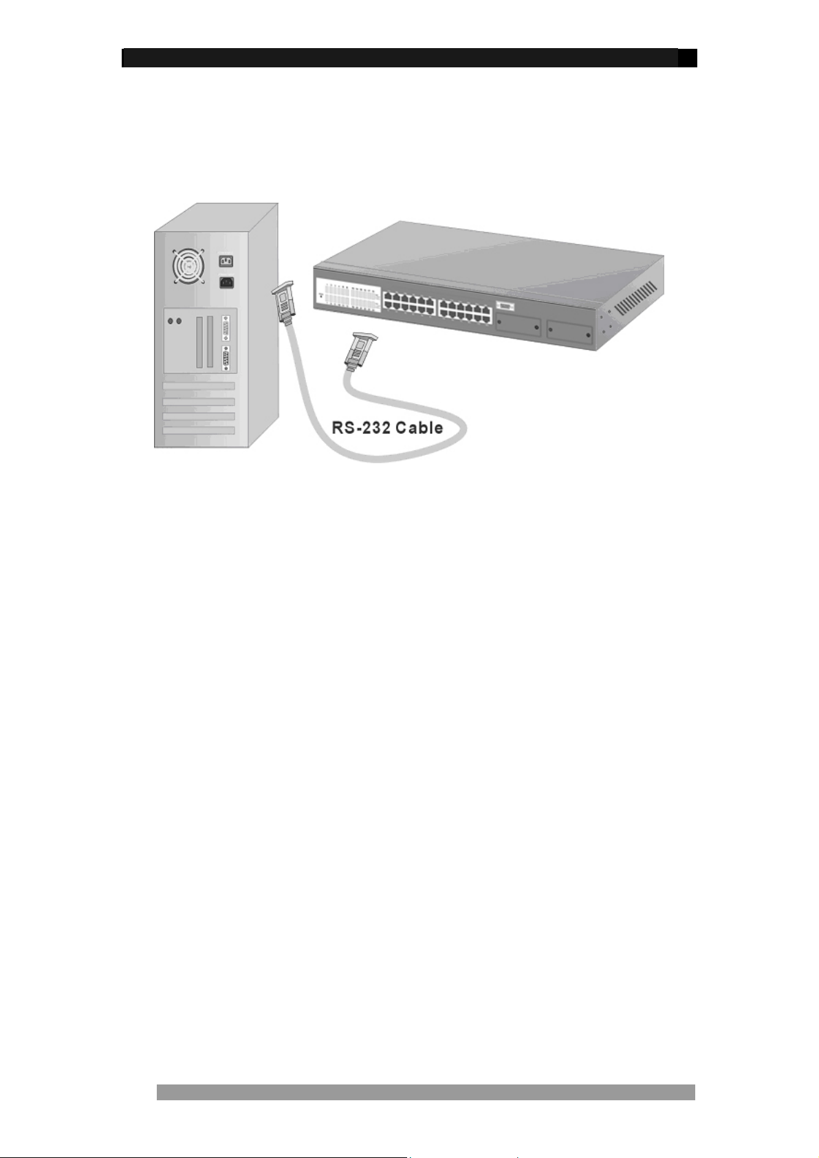
The Console port is a male DB-9 connector located on the front panel of the Switch that
enables a connection to a PC or terminal for monitoring and configuration. Use the supplied
RS-232 cable with a female DB-9 connector to connect a terminal or PC to the Console port.
Figure 8. Connecting the 24 Port Stackable Managed Switch to a terminal via
RS-232 cable
Quick Start Guide
If you do not need to apply VLANS, Quality of Service, Stacking functionality, adjust any
settings or manage the Switch via the network, then the Switch can be used “straight-fromthe-box” to carry network traffic. In that case, no further action is needed. If you want to use
the management settings or controls, then a little work is needed to configure the Switch.
1. After the installation is complete and AC power is applied, the Switch loads its
operating code from memory and performs a full power-on self test that takes about
30 seconds to complete.
2. Configure the PC terminal emulation program, such as HyperTerminal, to allow it to
communicate with the Switch via the supplied serial cable connected to the front
panel Console port. See page11 for details
3. After configuring the emulation program press <enter> and input root in lower case
letters for both the User Name and Password. The main menu screen will be
displayed. Use either <tab> or cursor keys to navigate up and down the menu. Select
the item using the <enter> key. The <esc> key will return to the previous menu level.
4. If the Switch is to be managed over the network using Telnet, SNMP or the web
browser, then an IP address needs to be assigned to the Switch. See page 18 for
details.
5. Once an IP address has been assigned to the Switch, it should be possible to PING
the Switch over the network. This will prove that the Switch is present and responding
correctly to network requests.
6. Now that the Switch can be accessed over the network, use a web browser
application to open up the configuration screens. Enter the Switch’s IP address into
the web browser URL field and use the same user name and password set as in 3
above.
7. Using the preferred method (console, Telnet or web browser), configure the Switch to
meet the requirements. Always save the configuration at the end of each action.
8. If you need to revert the Switch back to the factory default configuration, then see
page 41.
Product Number 0-1591099-x © Tyco Electronics 2005 Issue 1
Page 11
24 Port Stackable Managed Switch – User Guide Page 11
Management Using The Console
Configuring the Console Interface
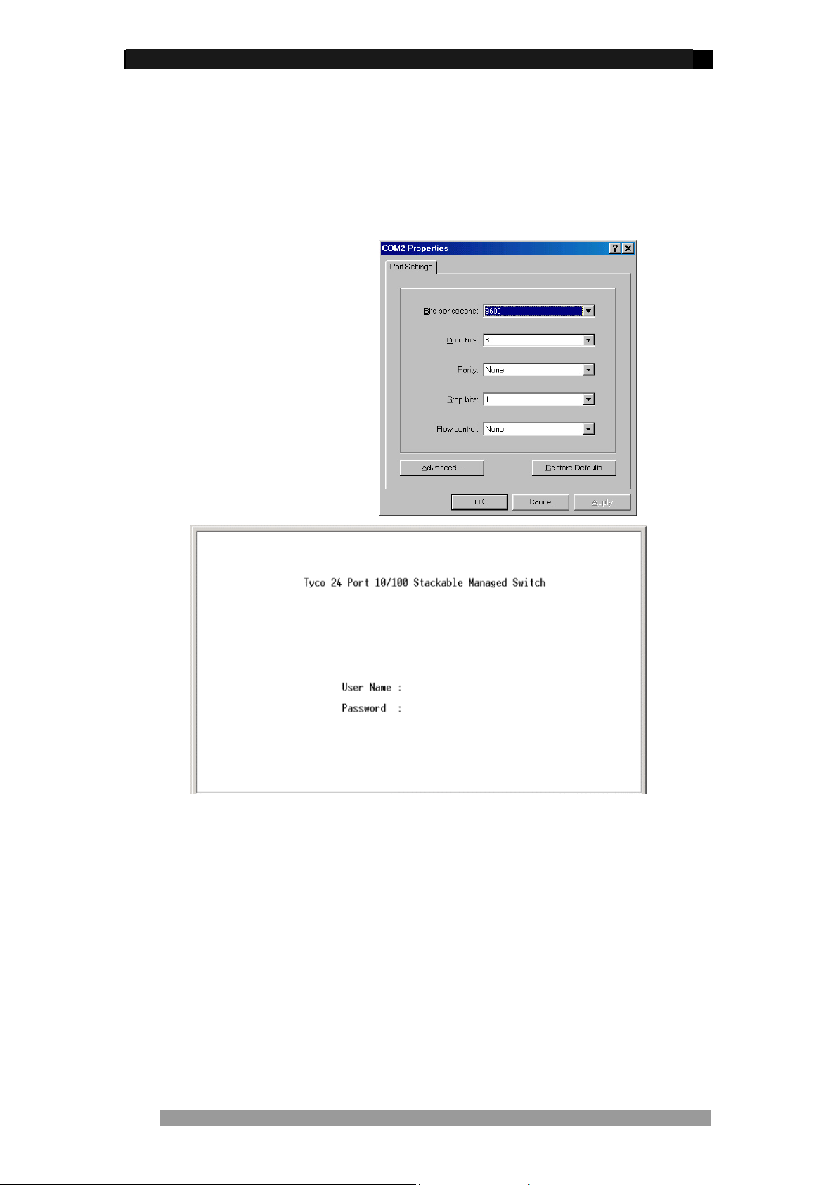
When the connection between Switch and PC is complete, turn on the PC and run a terminal
emulation program such as Hyper Terminal and configure its communication parameters to
match the following default characteristics of the console port:
Baud Rate: 9600 bps
Data Bits: 8
Parity: none
Stop Bit: 1
Control flow: None
Figure 9. Communication
parameters settings
Figure 10. Initial login screen
After setting the communication parameters, click “OK“ on the PC. Press <enter> and when
the screen displays the initial login screen as above, enter root in lower case letters for both
the User Name and Password. The Main Menu Screen of console management appears.
NOTE: If an IP address has been assigned to the Switch then it also possible to manage the
Switch remotely using Telnet. The management menu structure is exactly the same as from
console.
Product Number 0-1591099-x © Tyco Electronics 2005 Issue 1
Page 12
24 Port Stackable Managed Switch – User Guide Page 12
Menu Navigation
To navigate all these menus, use the following keys:
• Tab: Move the cursor to next item or right arrow key
• Backspace: Move the cursor to previous item or left arrow key
• Enter: Select the item.
• Spacebar: Toggle selected item to next value in sequence
• Esc: Go back to the action list or the previous menu
Note: Most menus have an action line at the bottom of the screen. This provides basic
context instructions such as Edit, Apply and Quit
Main Menu Screen
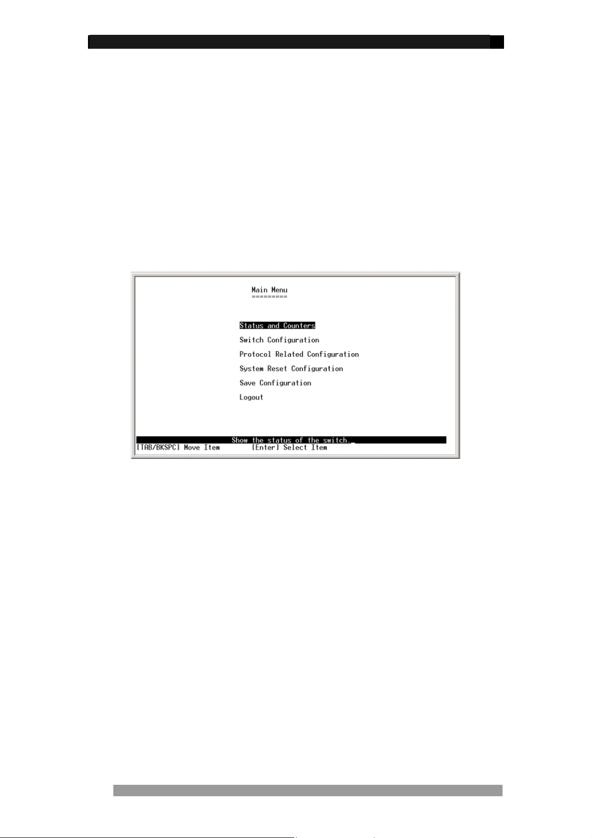
After login the screen below is displayed. Use the <tab> or cursor keys to step through the
sub-menus. Select the required sub-menu using the <enter> key.
Figure 11. Main Menu Screen
The sub-menus are:
• Status and Counters: Displays Port Status, Port Counters and System Information
• Sw itch Configuration: This large menu enables the configuration of key functions
such as IP address, Ports, Trunking, Mirroring, VLANs, QoS, Security, Broadcast
filtering etc.
• Protocol Related Configuration: Enables the configuration of Spanning Tree,
SNMP, GVRP and LACP.
• System Reset Configuration: Restores factory default values, restarts the Switch
and TFTP functions such as update firm ware, Restore/Backup configuration.
• Save Configuration: Saves the current configuration to the switches permanent
memory.
Product Number 0-1591099-x © Tyco Electronics 2005 Issue 1
Page 13
24 Port Stackable Managed Switch – User Guide Page 13
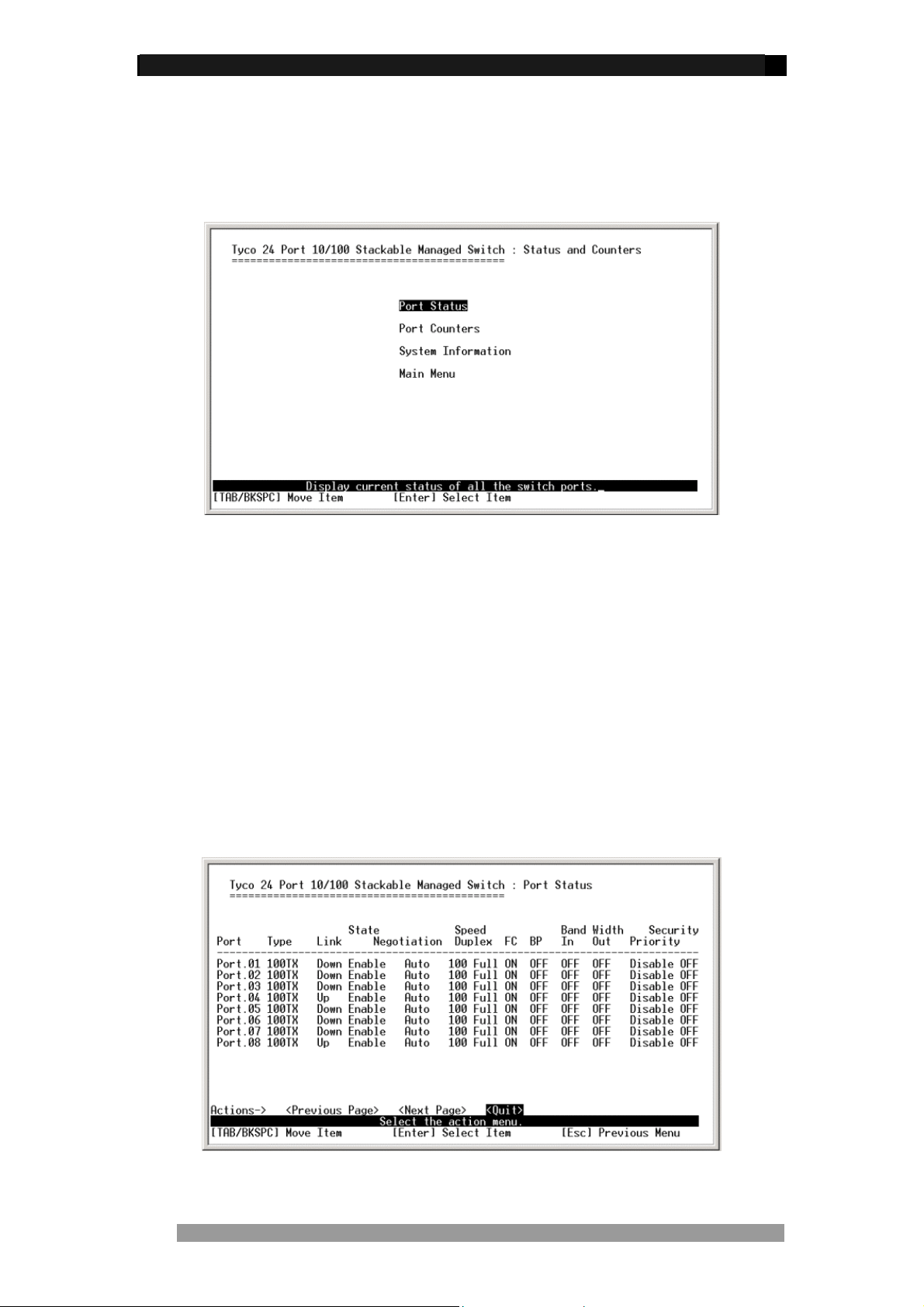
Status and Counters
In Status and Counters, you can view port status, counters, and system information. Press the
<tab> to choose item, and press <enter> key to select item.
Figure 12. Status and Counters main configuration screen
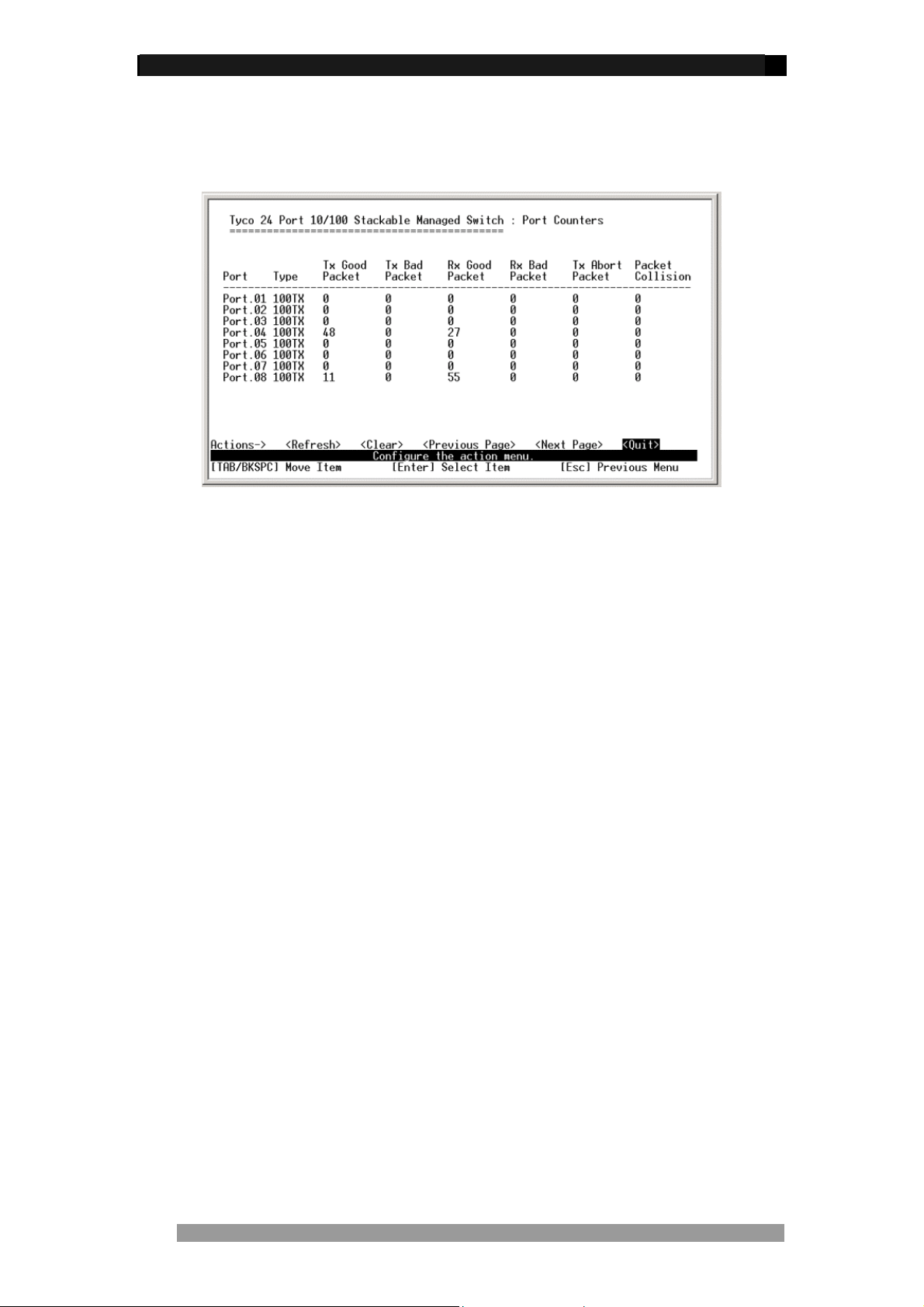
Port Status
This read-only screen lists the status of every port. Select the <previous page> and <next
page> to scroll through the full port list.
• Type: Displays the port type.
• Link: Displays link status. UP is a valid working link, and Down is no link.
• State: Displays if port is Enabled or Disabled by management
• Negotiation: Displays the auto negotiation status.
• Speed Duplex: Displays port speed and duplex mode.
• FC: Displays the flow control status – On or Off
• BP: Di splays backpressure status – On or Off
• Bandwidth In/Out: Displays bandwidt h In/out control status.
• Priority: Displays the port priority status. Enabled or Disabled.
• Security: Displays the port security status. On or Off.
Figure 13. Port status Screen
Product Number 0-1591099-x © Tyco Electronics 2005 Issue 1
Page 14
24 Port Stackable Managed Switch – User Guide Page 14
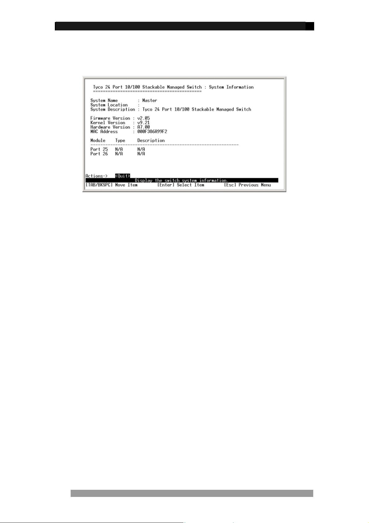
Port Counters
Displays real-time counter values for each port. This information can be especially useful
when troubleshooting link and port problems.
Figure 14. Port counter Screen
These counters display both transmitted and received packet counts, together with the
number of good and bad packets, includ ing the number of collisions (half-duplex mode only).
Select <refresh> to get newest port counter information and <clear> to reset the counters
from the action line
.
Product Number 0-1591099-x © Tyco Electronics 2005 Issue 1
Page 15
24 Port Stackable Managed Switch – User Guide Page 15
System Information
This screen displays useful information such as system name, location, firmware version,
MAC address and expansion module type if applicable. Note this is a read-only menu.
Figure 15. System Information Screen
Product Number 0-1591099-x © Tyco Electronics 2005 Issue 1
Page 16
24 Port Stackable Managed Switch – User Guide Page 16
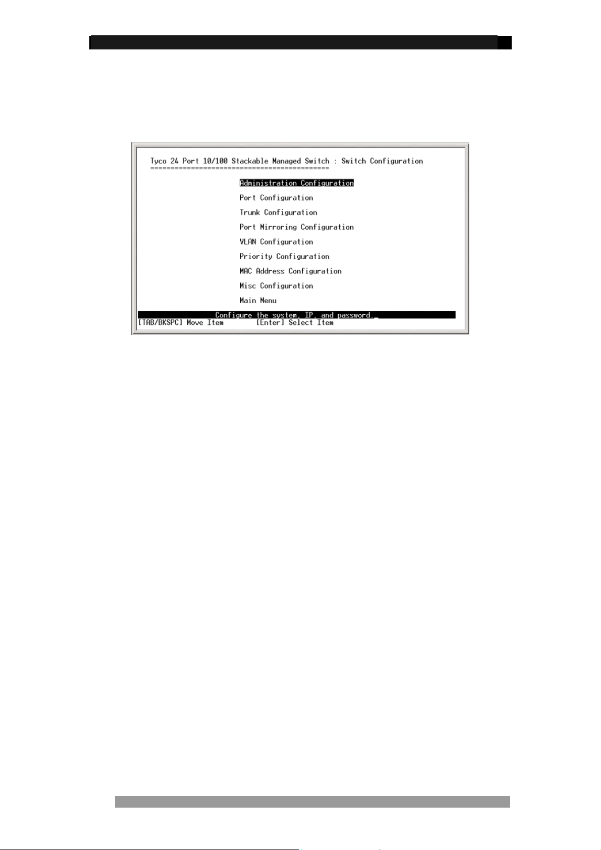
Switch Configuration
This menu, selected from the main menu, provides the primary method of configuring the
Switch and its associated values.
Figure 16. Switch Configuration Screen
The Switch configuration screens has the following sub-menus:
• Administration Configuration – used to configure device description information, IP
address configuration, User Name and Password configuration.
• Port Configuration – enable port attributes such as speed, duplex, state and
security to be configured.
• Trunk Configuration – allows configuration of LACP and Static port trunk groups.
• Port Mirroring Configuration – used to configure a port(s) to be mirrored
• VLAN Configuration – enables VLANS to be configured.
• Priority Configuration – controls the QoS settings on the Switch.
• MAC Address Configuration – Sets the MAC address security and filtering
attributes
• Misc. Configuration – Controls various settings including Stacking mode, Broadcast
Filtering, and MAC Ageing Timer
Product Number 0-1591099-x © Tyco Electronics 2005 Issue 1
Page 17
24 Port Stackable Managed Switch – User Guide Page 17
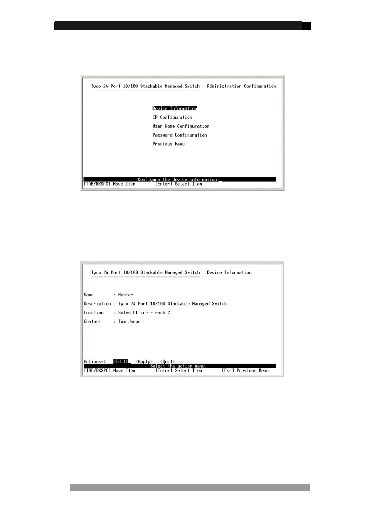
Administration Configuration
The Administration Configuration screen, selected from the Switch Configuration menu,
allows the configuration of device information, IP address, login username and password.
Figure 17. Administration Configuration Screen
Device Information
In this menu you can change device name, description, location and contact details. Select
the <edit> mode from the action line and edit the required fields, use the <tab> key to move
to the next field. When configuration is complete use the <esc> key to move back to the
action line and <apply> the changes.
Figure 18. Device Information Screen
Product Number 0-1591099-x © Tyco Electronics 2005 Issue 1
Page 18

24 Port Stackable Managed Switch – User Guide Page 18
IP Configuration
This screen is used to set the IP address, Sub-Net Mask and Default Gateway, DHCP client
functionality for the Switch. These settings are only required if the Switch is to be managed
over the network using Telnet, a web browser or SNMP.
Figure 19. IP Configuration Screen
This menu enables the IP address of the Switch to be configured. To change the IP Switch
setting:
1. Use the <tab> to highlight the <edit> field in the action line and press <enter>
2. The cursor will highlight the DHCP client field.
3. Use <tab> key to highlight the IP address field.
4. Enter the new IP Address as required.
5. Use <tab> key to highlight the Subnet Mask field.
6. Enter the Subnet mask address as required.
7. Use <tab> keys to highlight the default gateway field.
8. Enter the IP address of the default gateway as required.
9. Use the <esc> key return to the action line and then tab to the <apply> field and then
select the <apply> using the <enter> key to save the IP address changes.
10. Navigate up to the Main Menu using the <esc> key and then select the Save
Configuration. This will save the IP address configuration to Fla s h Rom.
11. After saving the configuration reboot the Switch for IP address configuration to take
affect.
12. After rebooting the Switch it is advisable to check that IP changes have been made
current by checking the Administration Configuration>IP Configuration menu
again.
NOTE: The Switch can also acquire its IP configuration automatically via DHCP by enabling
DHCP client from the IP configuration screen.
Product Number 0-1591099-x © Tyco Electronics 2005 Issue 1
Page 19

24 Port Stackable Managed Switch – User Guide Page 19
Change User Name and Password
The Administration Configuration screen has separate options for changing the User Name
and the Password for the Switch. The default values are:
• User N ame = root
• Password = root
NOTE: User Name and Password are case-sensitive.
To change either value, select the required option in the Administration Configuration screen
and the select the <edit> mode from the action line. Make the change and then quit from the
edit mode using <esc> key. Ensure that the new User Name and Password is saved by
selecting the <apply> option in the action line.
Figure 20. Password Configuration Screen
Product Number 0-1591099-x © Tyco Electronics 2005 Issue 1
Page 20

24 Port Stackable Managed Switch – User Guide Page 20
Port Configuration
This menu section controls the port configuration of the Switch and is selected from the
Switch Configuration menu screen. The following port attributes can be configured from this
menu:
• Port State
• Auto-Negotiation Mode
• Port Speed and Duplex Mode
• Port Flow Control
• Port Back Pressure
• Bandwidth In/Out
• Priority
• Security
Figure 21. Port Configuration Screen
Selecting the required Port Attribute
To edit the attribute of a selected port, use the <tab> key to move the cursor in the action line
to the <edit> mode. Then press the <enter> key and the cursor will highlig ht the Enable
status of Port 1. Use the <tab> key to navigate to the required port attribute and then u se the
<spacebar> key to toggle the values of that attribute. Use the <backspace> key to move to
the previous port attributes. Ensure that port configurations are saved by selecting the
<apply> in the action line.
Port State
This allows the port to be enabled or disabled by management. The default is enabled
allowing packets to be transmitted and received.
Port Negotiation
This allows the ports to be configured for Auto or Force. If configured for ‘Auto’ the port will
auto-negotiate speed and duplex with the its connected neighbour’s port. If configured for
‘Force’ then the port is set to speed and duplex as defined in the speed/duplex attribute. The
default is Auto.
Port Speed/Duplex
This controls the speed and duplex capability of a port. If negotiation is ‘Auto’ then the port will
advertise to the neighbour port its capability and will try and negotiate this capability. If
negotiation is set to ‘Force’ the speed and duplex are fixed.
Product Number 0-1591099-x © Tyco Electronics 2005 Issue 1
Page 21

24 Port Stackable Managed Switch – User Guide Page 21
Port Flow Control (FC)
This allows a full-duplex port to negotiate with connected equipment to implement a flow
control process using embedded Pause frames. The default setting is ON.
Back Pressure (BP)
This allows a half-duplex port to use back pressure as a method of flow control. The default
is OFF.
Bandwidth In/Out
Limits a port transmit and receive bandwidth. The bandwidth limiting can be configured
between 0 - 999 in 100Kbps increments. The default is 0, which is no rate limiting.
Priority
Configures a port to be high or low priority. Packets entering this port will be assigned a
priority and will follow the rule as defined in the Priority Configuration menu. The default is
Disable.
Security
Stops a port from learning new MAC addresses, which is useful when security is needed to
disallow an unauthorized connection to the port. This can be used in conjunction with Static
MAC Address Configuration to allow only a known and authorized MAC address to use this
port. The default is OFF.
Product Number 0-1591099-x © Tyco Electronics 2005 Issue 1
Page 22

24 Port Stackable Managed Switch – User Guide Page 22
Trunk Configuration
The Switch supports trunk groups between Switches. This scheme combines ports to become
an aggregate link to increase the bandwidth available between Switches using the standard
IEEE802.1ad (LACP) or Static Trunks. Up to 4 ports can be assigned to a trunk and the
Switch supports up to 7 trunks.
NOTE: LACP trunk ports must be full duplex and same speed.
Figure 22. Trunk Configuration Screen
Select Trunk Configuration from Switch Configuration menu and use the <tab> key to move
the cursor in the action line and select <edit> mode. It is now possible to use the <tab> and
<backspace> keys to navigate through the ports and add ports using the <spacebar> into a
trunk group (T1 to T7). Ports that are members of trunk are indicated by ‘*’. Having chosen
which ports to add into the Trunk Group navigate to the appropriate group and use the
<spacebar> to enable LACP or Static groups. Ensure that the Trunk Group configuration is
saved by selecting the <apply> in the action line. For further configuration details of LACP
trunk group, please refer to ‘LACP Configuration’ on page 36 in this manual.
Product Number 0-1591099-x © Tyco Electronics 2005 Issue 1
Page 23

24 Port Stackable Managed Switch – User Guide Page 23
Port Mirroring Configuration
Port mirroring is a method of duplicating traffic seen on a particular port and sending it to
another port. This is used for analyzing traffic using a network sniffer. The port being
monitored is called the Mirrored port and the port used to analyze the traffic is called the
Analysis port.
Figure 23. Port Mirroring Screen
Select Port Mirroring from the Switch Configuration menu and then from the action line select
<edit>. By default port mirroring is disabled. Use the <spacebar> to enable port mirroring.
The screen above will now be displayed. Again using the <spacebar> select the Mirroring
State. There are three options:
• RX: Received packets are only sent to the Analysis port
• TX: Transmitted packets are only sent to the Analysis port
• Both: Received and Transmitted packets are sent to the Analysis port.
Next using the <tab> key navigate to the Analysis port and select which port, using the
<spacebar>, is to be the Analysis Port. Again using the <tab> key scroll down through the
port list to select which port(s) is to be mirrored. Make the selection us ing the <spacebar>
which is indicated by a ‘*’. Ensure that the Port Mirroring Configuration is saved by selecting
<apply> in the action line. Please disable Mirroring State when finished, as Mirroring is very
CPU intensive.
Product Number 0-1591099-x © Tyco Electronics 2005 Issue 1
Page 24

24 Port Stackable Managed Switch – User Guide Page 24
VLAN Configuration
This menu section controls the VLAN configuration of the Switch and is selected from the
Switch Configuration menu screen. The Switch supports the following VLAN modes:
Port Based,
802.1Q
The default configuration is Disabled.
Figure 24. VLAN Configuration Main Screen
This menu allows basic control of the VLAN and its membership. Select the VLAN Conf igure
menu option and a new screen is displayed. If the Switch is in the default setting of Disabled,
then this will need to be changed to the required VLAN type listed above. Use the <edit> key
in the action line to move into the options area of the screen. Then use the <spacebar> to
toggle through the VLAN options. Having selected the required VLAN type use <esc> to
return to action line and <apply> changes.
Product Number 0-1591099-x © Tyco Electronics 2005 Issue 1
Page 25

24 Port Stackable Managed Switch – User Guide Page 25
Port Based VLAN
Having selected Port Based VLAN in the VLAN Configure menu, the next task is to create
and assign ports into the VLAN. This is achieved by selecting ‘Create VLAN Group’ from the
main VLAN Configuration menu. The following information is required:
• VLAN Name
• VLAN Group ID
• VLAN Port Membership
VLAN Name
This is a local value intended to provide a simple description of the VLAN, such as Sales,
Accounts etc.
VLAN Group ID
This is used to provide a number identifier for the specific VLAN. The legal range is 1 to 4094,
with 1 being the default value. The VLAN Group ID must be a unique number for each VLAN.
VLAN Port Membership
To assign ports to a VLAN use the <tab> key to scroll through the port list and then the
<spacebar> to toggle the membership status between No and Member. Select <previous
page> and <next page> from the action line to see further ports in the list. Select the required
ports to be members of this VLAN and then use <esc> to move to the action line and then
<apply> the settings.
Product Number 0-1591099-x © Tyco Electronics 2005 Issue 1
Page 26

24 Port Stackable Managed Switch – User Guide Page 26
IEEE802.1Q VLANS
This is a more complex form of VLAN that reacts to the tagging field in the Ethernet packets.
Unlike Port Based VLANS, where VLANS created are only significant to the local Switch,
802.1Q VLANS can exist across multiple Switches. The connection between these Switches
is called an 802.1Q trunk.
Figure 25. 802.1Q VLAN Configure Screen
1. Having selected 802.1Q in the VLAN Configure Menu the above is displayed.
2. Use the <tab> to move into the VLAN ID Range and select required VLAN ID range
by pressing <space>. Again using the <tab> key to move into the port field of the
menu. Enter the number of the tagged VLAN ID directly into the VLAN ID field. If the
device connected to this port does not support tagged VLANS, the ingress traffic will
have the specified default tag number added to each packet. This allows legacy
devices that do not support tagging to interoperate with tagged VLAN systems.
3. Use the <tab> key to move into the Ingress Filter field of the menu. Use the
<spacebar> to toggle between Disable and Enable. When this filter is Enable
(default), then only ingress packets with an identical VLAN tag to the port VLAN ID
will be forwarded. If Disable, all tagged packets will be forwarded.
4. Use the <tab> key to move into the Acceptable Frame Type field of the menu. Use
the <spacebar> key to toggle between All and Tag O n l y . If All then all tagged and
non-tagged packets will be forwarded. If Tag O nl y then only ingress packets with a
tag will be forwarded.
Product Number 0-1591099-x © Tyco Electronics 2005 Issue 1
Page 27

24 Port Stackable Managed Switch – User Guide Page 27
Create VLAN Group
This menu section controls the VLAN Group Membership of the Switch and is selected from
the VLAN Configuration menu. This allows specified ports to be made members of specific
VLAN groups. It is also possible to create a Security VLAN from this menu. A Security VLAN
allows only members of this VLAN to manage the Switch using Web, Telnet, or SNMP. There
can be only one Security VLAN. Having selected Create VLAN Group from the VLAN
Configuration Menu and chosen if a Security VLAN is needed the following screen is
displayed:
Figure 26. Create VLAN Group: 802.1Q Screen
VLAN Name
This is a local value intended to provide a simple description of the VLAN, such as Sales,
Accounts etc. If a Security VLAN has been selected this field will display ‘Security_VLAN’ and
cannot be changed.
VLAN ID
The VLAN ID is used to provide a number for the specific VLAN. The legal range is 1 to 4094,
with 1 being the default value. The VLAN ID must be a unique number
Protocol VLAN
It is possible to assign ports to a VLAN based on protocol. The d efault is None.
Member
Ports that are to be members of this VLAN are specified in the table by using <tab> key to
move to the Port area and then the <spacebar> key to toggle the membership status
between No, Untagged, and Tagged. Select the required ports to be members of this VLAN
and then use <esc> to move to the action line and then <apply> the settings changes.
Product Number 0-1591099-x © Tyco Electronics 2005 Issue 1
Page 28

24 Port Stackable Managed Switch – User Guide Page 28
Edit/Delete VLAN Group
This menu section is selected from the VLAN Configuration menu and allows an existing
VLAN group to be edited or even deleted. When this option is selected, all existing VLAN
groups on the Switch are displayed. Use the <tab> key to navigate to the <edit> field or
<delete> field in the action line and then use the <enter> key to select the option.
If <edit> was selected, the cursor now moves to the VLAN group are. Use the <tab> key to
select the required group to edit and make the required changes. Use the <esc> key to return
to the action line and then <apply> the changes.
If <delete> was selected, the cursor now moves to the VLAN group. Select the required
group using the <tab> and then <enter> to delete the VLAN group. Use the <esc> key to
return to the action line and then <apply> the changes.
NOTE: The Default VLAN cannot be deleted.
Group Sorted Mode
This menu controls the order VLANS are listed in the ‘Edit/Delete VLAN Group’. The VLANS
can either be sorted using VLAN ID (Numerically) or by VLAN Name (Alphabetically). Select
<edit> from the action line and use the <spacebar> to toggle between VLAN ID and Name.
Having selected the required order method, use the <esc> key to return to action line and
then <apply> the changes.
Figure 27. Group Sorted Mode Screen
Product Number 0-1591099-x © Tyco Electronics 2005 Issue 1
Page 29

24 Port Stackable Managed Switch – User Guide Page 29
Priority Configuration
The Switch supports basic QoS operation with the ability to map the 0-7 priority levels in
IEEE802.1p to either the low or high priority egress queue buffers. In addition the relative
weighting of high to low packets egressing from the Switch can also be programmed. This
menu section is selected from the Switch Configuration menu screen.
Figure 28. Priority Configuration Screen
Modify the Egress Mapping
After the Priority Configuration menu has been selected, the priority screen is displayed and
this enables the control of the QoS egress mapping. To adjust the mapping, select <edit>
from the action line and the cursor moves to the first map level. Use the <spacebar> key to
toggle between <low> and <high> settings. The default mapping is Levels 0-3 are Low
priority and Levels 4-7 are High priority.
Modify the Egress Weighting
The Switch can be programmed to control the relative flow of high and low priority packets
from the egress port. Note that this weighting algorithm is applied to the whole Switch and not
specific ports. To adjust the weighting algorithm, select <edit> from the action line and the
cursor moves to the first map level. Use the <tab> key to move through the mapping options
to the QoS Mode field. Then select the required algorithm using the <spacebar>. The
weighting options are:
All High Before Low – All high priority packets are sent before low priority (default)
Weight Round Ratio x:1 – The Switch will send x high priority packets followed by a low
priority packet (x can be between 2 to 7)
First Come First Serve – The first packet to arrive is sent out first (no actual priority is
applied).
Use the <esc> key to return to the action line and ensure that the settings are saved by
selecting the <apply> field.
Product Number 0-1591099-x © Tyco Electronics 2005 Issue 1
Page 30

24 Port Stackable Managed Switch – User Guide Page 30
MAC Address Configuration
This menu section is selected from the Switch Configuration menu screen and enables
configuration of the static or filtered MAC addresses. These settings are only needed for
certain security operations and are not generally used. It is also possible from this option to
view MAC addresses that have been learnt by the Switch.
In some instances, it is necessary to manually apply a fixed or static address into the tables of
the Switch. When you add a static MAC address, it remains in the Switch's address table,
regardless of whether the device is physically conn ected to the Switch. This saves the Switch
from having to learn a device's MAC address.
Static MAC Address
From the MAC Address Configuration menu select the option Static MAC Address. A new
menu is displayed listing the existing static MAC addresses. Select <add> from the action
line. A new menu is displayed that requests the MAC address value and the physical port that
is associated with the static address value. If VLANS are configured it will also request a
VLAN ID. When these values have been entered, use the <esc> key to return to the action
line and then select the <apply> to ensure that the MAC values are stored. The menu will
display each static MAC address configured, the associated port a nd VLAN ID.
Filtering MAC Address
There maybe times when filtering packets based on the destination MAC address is needed.
This is achieved using Filtering MAC Address menu, selected from the MAC Address
Configuration menu. After selecting this option a new menu is displayed listing the current
MAC addresses that are being filtered and their associated VLAN ID. Select <add> from the
action line. A new menu is displayed that requests the MAC address value to be filtered and if
VLANS are configured, the VLAN ID value. When these values have been entered, us e the
<esc> key to return to the action line and then select <apply> to ensure the configuration is
saved.
All MAC Addresses
There can be occasions when it is useful to determine what MAC addresses have been learnt
on a port for troubleshooting reasons. Select All MAC Addresses from the MAC
Configuration Menu. Now choose <select> from the action line and use the <spacebar> to
list port number options. Select the port to be viewed by pressing <enter>. A new screen is
now displayed showing a list of MAC addresses that have been learnt on this port, and their
associated VLANID. The Status field shows if the MAC address is Dynamic (learnt) or Static.
NOTE: This option currently only works on a Standalone or Master Switch
Product Number 0-1591099-x © Tyco Electronics 2005 Issue 1
Page 31

24 Port Stackable Managed Switch – User Guide Page 31
Misc Configuration
This menu is selected from the Switch Configuration menu screen and enables configuration
of the remaining Switch-specific variables such as MAC Ageing time, Broadcast Storm,
Stacking mode etc.
Figure 29. Misc Configuration Screen
MAC Address Aging Time
This setting specifies the time that a dynamic MAC address can remain in the Switch tables
before the value is “aged out”. The valid range is 300 to 765 seconds. The default value is
300 seconds, which is the industry standard duration. This value rarely needs to be modified.
Broadcast Storm Filter
This is used to limit the number of packets flowing through the Switch that do not have
associated entries in the Switch tables (Destination Look-Up Failures) or excessive broadcast
transmissions. In some instances, this high level of DLF/broadcast traffic can degrade
network performance. To minimize this problem, the Switch can be programmed to limit the
amount of broadcast traffic that can flow through the Switch. In normal networks, only a few
percent of traffic would normally be broadcast s.
This mode is accessed from the Misc. Configuration screen and is changed by selecting
<edit> from the action line and then using <tab> key for navigation to Broadcast Storm field.
Use the <spacebar> to step through the valid thresholds:
• N/A (Disabled)
• 5%
• 10%
• 15%
• 20%
• 25%
The default value is 5%. After the required threshold value has been selected, use the <esc>
key to return to the action line and then select <apply> to store the value.
Product Number 0-1591099-x © Tyco Electronics 2005 Issue 1
Page 32

24 Port Stackable Managed Switch – User Guide Page 32
Max Bridge Transmit Delay Bound
This control is used in association with QoS Configuration to control the time that packets
may be queued in the Switch. If the packet is stored in the Switch for a time exceeding the
specified amount, then it is dropped. These settings do not need to be changed except for
networks where time-sensitive prioritized traffic is used. The default is OFF.
Low Queue Delay Bound
If low priority packets are queued in the Switch for longer than the ‘Low Queue Max Delay
Time’, then the Switch will forward the packet immediately. Default is Disable.
NOTE: Ensure that ‘Max Bridge Transmit Delay Bound’ is ON before enabling ‘Low Queue
Delay Bound’.
Low Queue Max Delay Time
Defines the maximum time a low priority packet will be queued before being sent. The valid
range is 1 to 255ms. The default max delay time is 255ms.
Collisions Retry Forever
In the default enable state the Switch will attempt to send a packet forever in the event of
collisions. If disabled the Switch will re-transmit the packet up to 48 times in the event of
collisions and after this the packet will be dropped.
Hash Algorithm
This controls the method used to maintain the MAC table. Either CRC Hash or Direct Hash.
The default is CRC Hash.
IFG Compensation
When enabled Inter-Frame Gap is forced to 0.96 microseconds. This maintains compatibility
with LAN cards and other network equipment. If disabled then the IFG remains unchanged.
The default is enabled.
IP Stacking Group ID
Assigns the stacking group ID, which is used to control stack membership. Switches
belonging to the same stack must be assigned the same stacking group ID. The valid range is
0 to 65535).
IP Stacking Mode
There are three stacking modes that can be configured on the Switch:
• Disable – The Switch is not participating in a stack and is standalone (default)
• Master – The Switch is the main controller Switch in the stack. There can be only one
configured Master in the stack.
• Slave – All other Switches in the stack are configured as Slaves. Web management
of these Slave Switches is preformed via the Master Switch.
IP Stacking System Information
This is a meaningful name that can be given to the Switch e.g. Sales Switch – rack 4, that is
displayed when using a web browser to manage the Switch.
Please refer to page 42 for further details about Stacking.
Product Number 0-1591099-x © Tyco Electronics 2005 Issue 1
Page 33

24 Port Stackable Managed Switch – User Guide Page 33
Protocol Related Configuration
This menu option enables the following protocols to be configured:
• STP/RSTP Spanning Tree Protocol
• SNMP Simple Network Management Protocol
• LACP Link Aggregation Control Protocol
• IGMP/GVRP (Internet Group Management Protocol/Generic Attrib ute Registration
Protocol
• RADIUS Remote Authentication Dial-i n User Service (802.1x)
RSTP Configuration
Spanning-Tree Protocol is a link management protocol that provides path redundancy while
preventing undesirable loops in the network. For an Ethernet network to function properly,
only one active path can exist between two stations. The Switch supports two versions of this
protocol:
• RSTP Rapid Spanning Tree Protocol (802.1w)
• STP Spanning Tre e Proto col (802.1d)
NOTE: In this current version of firmware Spanning Tree will not work across trunk links.
Having selected RSTP Configuration from the Protocol Related Configuration screen the
following menu is displayed:
Figure 30. RSTP Configuration Screen
Product Number 0-1591099-x © Tyco Electronics 2005 Issue 1
Page 34

24 Port Stackable Managed Switch – User Guide Page 34
RSTP Setup
To enable Spanning Tree highlight ‘Set RSTP Mode’ using the <tab> key and press <enter>.
The RSTP Setup screen will now appear. Select <edit> mode from the action line and use the
<spacebar> to toggle between STP modes. Choose either 802.1w (RSTP) or 802.1d
(Traditional Spanning Tree) depending what type of spanning tree protocol is required. Now
use the <esc> key to return to the action line and then <apply> the changes. Spanning Tree
is now enabled on the Switch.
System Configuration
This screen provides both information and configuration of the spanning tree protocol. Useful
information such as Root Bridge, Root Port and cost to root can be gathered from here. The
following parameters can also be changed from this menu:
• Priority – This parameter allows the control of Root Bridge in the STP network. The
lower the priority, the more likely this Switch will be elected as root. The valid range
is 1 - 65535.
• Max Age - The number of seconds the Switch waits for hello messages from root
bridge before deciding the root is unavailable and performing a reconfiguration. The
valid range is 6 - 40.
• Hello Time – This is the interval in time (seconds) that a root bridge sends BPDU
configuration messages. The valid range is 1 - 10.
• Forw ard Delay Time – The period in time (seconds) a Switch will wait (the listen
and learn period) before forwarding frames. The valid range is 4 - 30.
Per Port Setting
This screen allows the individual RSTP/STP values to be set on the required ports. . A port
with higher priority, lower path cost is less likely to be blocked if Spanning Tree Protocol
detects a network loop. The following can be configured:
• Path Cost – This parameter can be used to assign a higher or lower path cost to a
port. A port with a high path cost is more likely to be blocked. The valid range is 1 -
200000000.
• Priority – If path cost to root is equal then a port with a higher priority (lower
numerical value) is more likely to forward traffic. The valid rang e is 1 - 240.
• P2P – This parameter is used by RSTP to determine if the port is connected to a
shared or full-duplex link, which will affect RSTP state transaction. It is
recommended to keep this parameter with the default of Auto.
• Edge – This is a RSTP value. A port directly connected to end stations cannot
create a bridging loop. The default is true.
• Non STP – The status shown here indicates if the port is participating in STP.
Per Port Status
This is informational screen only and parameters cannot be changed. The STP status
of each port can be viewed. The following STP port statuses are:
• Role – indicates the STP role of the port
• St ate – determines the STP state of the port
• Path Cost – The port cost.
• P2P – The current P2P status of the port
• Edge – The current Edge status of the port
• STP Neighbor – shows if the port has a STP neighbor or not.
Product Number 0-1591099-x © Tyco Electronics 2005 Issue 1
Page 35

24 Port Stackable Managed Switch – User Guide Page 35
SNMP Configuration
This set of screens configures the Switch to become an active SNMP agent. There are
several sub-menus available:
• System Options
• Comm unity Strings
• Trap Managers
System Options
This sub-menu is used to specify the System Name, Contact and Location. This information
can be useful when querying a Switch from a network management station.
Community Strings
In the SNMP Community Menu, it is possible to create or edit communities and customize
their access rights.
When the rights value is Read Only, this enables SNMP requests accompanied by this
community string to display MIB variable information.
When the rights value is Read/Write this enables SNMP requests accompanied by this
community string to display and set MIB variable information.
Trap Managers
A trap manager is a network management station (NMS) that receives traps from distributed
SNMP devices. The Switch will generate trap messages when a fault condition is detected.
Create a trap manager by entering the IP address of the NMS and a community string.
Product Number 0-1591099-x © Tyco Electronics 2005 Issue 1
Page 36

24 Port Stackable Managed Switch – User Guide Page 36
LACP Configuration
The Link Aggregation Control Protocol (LACP) provides a standardized means for grouping
up to four consecutive ports into a single dedicated connection. This feature can expand
bandwidth to a device on the network. LACP operation requires full-duplex mode.
NOTE: Before configuring LACP set a trunk group(s) from the Trunk Configuration menu.
Having selected LACP Configuration from the Protocol Related Configuration screen the
following menu is displayed:
Figure 31. LACP Configuration screen
Working Ports
This menu allows the control of how many active LACP ports will participate in the trunk. If an
active port fails then a standby port will join the LACP trunk.
E.g. If 4 ports have been configured to be in an LACP trunk and work ports is 3. Then 3 ports
will be active and 1 port will be in standby.
Note: It is not possible to create standby trunk ports if Static Trunks have been configured.
Figure 32. LACP Working Ports Screen
Product Number 0-1591099-x © Tyco Electronics 2005 Issue 1
Page 37

24 Port Stackable Managed Switch – User Guide Page 37
Having selected working ports from the LACP Configuration screen the above is displayed.
Select <edit> from the action line and enter the number of ports to be working port. Press
<esc> to return to the action line and <apply> to save the configuration.
State Activity
If a LACP trunk has been configured it is possible to set the port to the following modes:
• Active (default) – The port automatically sends LACP packet to the neighbor device
to establish a trunk connection
• Passive – The port waits for a LACP packet from the neighbor device before
establishing a LACP trunk connection.
NOTE: One or both ends of the trunk link must be set to ‘Active’.
Figure 33. LACP State Activity Screen
After selecting this option from the LACP configuration the screen above will appear. Now
select <edit> from the action line. Use the <tab> key to highlight the port to be modified and
press the <spacebar> to toggle between Active and Passive modes. Having made the
selection press <esc> to return to the action line and <apply> to save the configuration.
Product Number 0-1591099-x © Tyco Electronics 2005 Issue 1
Page 38

24 Port Stackable Managed Switch – User Guide Page 38
Group Status
This is an informational screen only and provides the status of both LACP and Static trunk
groups. This option can be selected from the LACP Configuration screen.
Figure 34. LACP Group Status Screen
IGMP/GVRP Configuration
This screen, selected from the Protocol Configuration screen is used to enable or disable the
IGMP and GVRP, and to configure the IGMP mode. The Internet Group Management Protocol
(IGMP) is a protocol that manages IP multicast traffic.
The Generic VLAN Registration Protocol allows automatic VLAN configuration between
Switches and its nodes. A node that that supports GVRP can send a request to the Switch to
join a specific VLAN.
Figure 35. IGMP/GVRP Configuration Screen
Select <edit> from the action line and highlight the required field to modify using the <tab>
key. Use the <spacebar> to toggle through the settings. IGMP and GVRP can be set to either
Enable or Disable. Query Mode can be set to enable, disabled or auto. Having made the
selection use <esc> key to return to the action line and <apply> to save the configuration.
Product Number 0-1591099-x © Tyco Electronics 2005 Issue 1
Page 39

24 Port Stackable Managed Switch – User Guide Page 39
802.1x Configuration
The 802.1x is a security protocol that provides a means of authenticating and authorizing
devices attached to a LAN port on the Switch, and preventing access to that port when
authentication and authorization fails. Having selected 802.1x Configuration from the Protocol
Configuration screen the following is displayed:
Figure 36. 802.1x Configuration Screen
802.1x Setup
This menu is used to enable to the 802.1x protocol. By default the protocol is disabled. To
enable the protocol select 802.1x Setup from the 802.1x Configuration menu. Using the <tab>
key select <edit> from the action line and use the <spacebar> to toggle to Enable. Now
press <esc> key to return to the action line and <apply> to save changes. The 802.1x
protocol is now running on the Switch.
System Configuration
This is the main configuration screen for the 802.1x protocol and is selected from the 802.1x
Configuration screen. Having selected this menu option the following screen is displayed:
Figure 37. 802.1x System Configuration Screen
Product Number 0-1591099-x © Tyco Electronics 2005 Issue 1
Page 40

24 Port Stackable Managed Switch – User Guide Page 40
The following parameters can be configured:
• Radius Server IP address – This is the IP address of the authentication server that
the Switch will use to authenticate and authorize.
• Shared Key - set an encryption key for use during authentication process with the
specified radius server. This key must match the encryption key used on the Radius
Server
• NAS, Identifier – A meaningful name used in authentication and accounting.
• Server Port - The UDP destination port number used to send authentication
requests to the Radius server.
• Accounting Port – The UDP destination port number used to send accounting
requests to the Radius server.
Per Port Setting
Using this menu option it is possible to configure the 802.1x authentication state of each port.
Having selected this menu option from the 802.1x Configuration it is possible to set specific
ports to the following authentication states
:
• Disable (defa ult) – Authentication is disabled on this port
• Reject – The port is held in an unauthorized state
• Accept – The port is held in an authorized state
• Authorize – The port will participate in the authentication process and the
authentication state will depend on the outcome of the authentication process
between the supplicant and the Radius server.
.
From the action line select <edit> and use the <esc> key to highlight the port that needs
changing. Use the <spacebar> to toggle between the required authentication states. Having
made the selection press the <esc> to return to the action line and <apply> to save the
changes.
Misc Configuration
Use this option to change the following 802.1x attributes. It is recommended to leave as
defaults unless certain of the consequences:
• Quiet Period - The number of seconds that the Switch remains in the quiet state
following a failed authentication exchange with the client (default 60 seconds)
• Tx Period – The number of seconds the Switch should wait for a response to an
EAP request/identity frame from the client before retransmitting the request (default
30 seconds)
• Supplicant Timeout - The number of seconds the Switch waits for a supplicant
response to an EAP request (default 30 seconds)
• Server Timeout – The number of seconds the Switch waits for a server response
to an authentication request. (default 30 seconds)
• Reauthorize Maximum –The number of times that the Switch will send an EAP-
request/identity frame before restarting the authentication proce ss (default 2)
• Reauth Period – The number of seconds the authorized clients must be re-
authenticated (default 3600 seconds).
Product Number 0-1591099-x © Tyco Electronics 2005 Issue 1
Page 41

24 Port Stackable Managed Switch – User Guide Page 41
System Reset Configuration
The following options can be selected from this menu:
• Factory Default
• System Reboot
• TFTP Configuration
Factory Default
This menu restores the Switch back to its original defaults. Select this option from the System
Reset Configuration. When prompted choose if current IP address and username/password
are to be kept after the factory default. After confirming the intention of restoring to factory
defaults, it is recommend that a system reboot is performed.
System Reboot
This option reboots the entire Switch as soon as it is selected. There is no confirmation step.
Only select this mode if you are sure that you want to reset the Switch
TFTP Configuration
From this menu option, selected from System Reset Configuration, it is possible to perform
the following:
• Update Firmware
• Restore Confi guratio n
• Backup Confi guration
Update Firmware
This option updates firmware running on the Switch from the TFTP server. Having selected
this option from the TFTP Configuration menu select <edit> from the action line. Enter the IP
address of the TFTP server and the file name to download. Use the <esc> to return to action
line and <apply> to start the download. When the file has downloaded choose to reboot the
Switch when prompted. The firmware is now updated.
NOTE: Check the version is updated from the System Information menu. If it remains
unchanged a factory default maybe needed.
Restore Configuration
This selection allows a saved Switch configuration file to be downloaded to the Switch. After
choosing this option from the TFTP Configuration menu select <edit> from the action line.
Now enter the IP address of the TFTP server and the file name of the configuration file to
download. Press <esc> to return to the action line and <apply> to start the download. If
successful a prompt will appear to confirm if a system reset is required. It is recommended
that a reset be performed. The Switch is now restored.
Backup Configuration
Use this option to upload and save a backup Switch configuration file to a TFTP server. After
choosing this option from the TFTP Configuration menu select <edit> from the action line.
Now enter the IP address of the TFTP server and the file name of the configuration file to
upload. Press <esc> to return to the action line and <apply> to start the upload. Check on the
TFTP server that the file has been saved.
Save Configuration
Any changes made to the configuration of the Switch needs to be saved. Otherwise after a
reboot of the Switch any configuration changes will be lost. Select this option from the Main
Menu and confirm the save.
Product Number 0-1591099-x © Tyco Electronics 2005 Issue 1
Page 42

24 Port Stackable Managed Switch – User Guide Page 42
IP Stacking
The Switch can be web managed in either a standalone or stacking mode. In stacking mode a
group of Switches (8 maximum) can be managed using a single IP address from a web
browser, which simplifies the management task. One Switch in the Stack is configured as the
‘Master’ Switch and all other Switches are configured as a ‘Slave’. Switches belonging to the
same Stacking group must have the same IP Stacking Group ID.
Note: After configuring an IP Stacking Group. Slave Switches can only be managed through
the Master Switch. It is not possible to Web/Telnet/SNMP Manage a Slave Switch directly.
IP Stacking Configuration
1. Select the IP Configuration menu on each Switch and assign a unique IP address to
all Switches that are to be stacked (NOTE: Only the Master Switch’s IP address is
used on the LAN. All other IP addresses assigned to Slave Switches can be reused
for other devices on the LAN. Ensure that assigned IP addresses are in the same
subnet.
2. To enable one Switch as Master, select Misc Configuration from Switch Configuration
menu and modify:
IP Stacking Group ID – Choose a unique ID, between 0 - 65535, to identify the
stacking group
IP Stacking Mode – Select this Switch to be Master
IP Stacking System Information – Give the Switch a meaningful name that will be
displayed when web managed.
Save the configuration
3. The next task is to configure all other Switches as Slaves. Select Misc Configuration
on each Switch and modify:
IP Stacking Group ID – Configure each Switch with the same ID as the Master.
IP Stacking Mode – Sele ct each Switch to be ‘Slave’
IP Stacking System Information – Give each Switch a meaningful name that will be
displayed when web managed.
Save the configuration
4. Now ensure all Switches are connected to the LAN and are in the same broadcast
domain (subnet). It is recommended that the Switches be directly connected to each
other.
Product Number 0-1591099-x © Tyco Electronics 2005 Issue 1
Page 43

24 Port Stackable Managed Switch – User Guide Page 43
The Stack is now configured. It should now be possible to manage the stack of Switches from
a web browser. In the URL field of the web browser enter the IP address of the Master
Switch. A similar window as below should appear:
Figure 38. Web Login Screen
Enter the Username and Password and click OK. The default s a re:
Username: root
Password: root
If username and password are correct the browser will display the stacked Switch group
homepage, which will look similar to:
Figure 39. Switch Homepage Screen
Product Number 0-1591099-x © Tyco Electronics 2005 Issue 1
Page 44

24 Port Stackable Managed Switch – User Guide Page 44
To ensure that the stack has been properly configured click on the ‘IP Stacking’ in the side
menu and a window similar to below will appear:
Figure 40. IP Stacking Screen
If the Stacking Configuration has been successful, then the IP Stacking screen will show a list
of MAC addresses and System names, which are Hyperlinks. It is now possible to manage
any member Switch in the stacking group by clicking on the Switch Hyperlink. The Switch
that is currently being managed is indicated by >> and <<. Having selected a Switch to
manage, any actions performed using this web interface will affect the selected Switch o nly.
NOTE: If a Stack of Switches needs to be disbanded using Web Based Management, then
Disable Stacking mode on the Slaves first, and lastly Disable Stacking mode on the Master
Switch.
Backup Master
The Stack will remain manageable if the Master Switch fails or looses network connectivity. If
this should happen then the BackupMaster will go active and maintain the manageability of
the Stack. The BackupMaster is elected by the lowest MAC address in the Stack and no user
configuration is needed. The IP Stacking screen (Figure 40.) is used to determine the current
Master and BackupMaster Switch.
NOTE: The IP address used to manage the Stack, after the Master Switch fails, remains
unchanged.
Product Number 0-1591099-x © Tyco Electronics 2005 Issue 1
Page 45

24 Port Stackable Managed Switch – User Guide Page 45
Web Based Management
Inside the Switch exists an embedded web server that allows administrators to manage the
Switch remotely. The Web Based management is a graphical interface, which some users
may find easier and more intuitive than other management methods.
The Web-Based Management supports Microsoft Internet Explorer 5.0 and above (plus other
web browsers). It is based on Java Applets with an aim to reduce network bandwidth
consumption, enhance access speed and present an easy viewing screen.
Configuring The Switch for Web Based Management
The Switch has the following default values that need to be adjusted to suit your network:
IP Address: 10.10.10.10
Subnet Mask: 255.255.255.0
Default Gateway: 10.10.10.254
User Name: root
Password: root
1. Obtain the correct local IP addresses from your network administrator and enter the
values from the console menu as detailed on page 17. This IP information has to be
entered via the console, as the web interface will not be accessible until the local IP
address values have been entered, saved and the Switch restarted.
2. After the Switch has been restarted with the new IP address, check that the Switch is
visible on the network by ‘pinging’ the address. If the Switch is present and correctly
configured, then the ‘ping’ will echo back a response message otherwise the message
“Request Timeout” will be displayed. Ensure that the Switch can be ‘pinged’ before
proceeding. Consult your system administrator for details of ‘pinging’. The syntax from
your PC is:
Start >Run> ping 162.109.37.13 –t
Where the 162.109.37.13 is the example IP address allocated to the Switch
The –t causes the ping test to run continuously.
3. After the ‘ping’ test has passed, ope n a web browser window (such as Microsoft Internet
Explorer) and enter the allocated IP address of the Switch into the URL field. For
example:
http://162.109.37.13
If all the settings are correct, then the browser will display a user name and password
box similar to the one below:
Figure 41. Web Login Screen
Product Number 0-1591099-x © Tyco Electronics 2005 Issue 1
Page 46

24 Port Stackable Managed Switch – User Guide Page 46
4. to the password box and enter the default password root. If the settings are correct,
then the browser will begin to render a new page showing the image of the Switch. This
is the home page of the Switch web management screen.
Figure 42. Web Browser Home Page Screen
It is recommended that you explore the menu bar in the left hand side of the screen. This
menu area controls the configuration, control and statistics elements of the Switch.
Product Number 0-1591099-x © Tyco Electronics 2005 Issue 1
Page 47

24 Port Stackable Managed Switch – User Guide Page 47
Port Status Screen
The most basic and useful menu is the read-only Port Status screen, which provides the
current status of each port.
Figure 43. Port Status Screen
This menu screen displays the read-only link status (Up/Down) of all ports together with the
Auto-negotiation mode, duplex mode and flow control settings. A ‘green’ port on the graphical
representation of the Switch also indicates the link status of a port that is UP. The
programmable port values can be changed in the Administrator > Port Controls Screen.
Product Number 0-1591099-x © Tyco Electronics 2005 Issue 1
Page 48

24 Port Stackable Managed Switch – User Guide Page 48
Port Statistics Screen
The port statistics screen enables the network administrator to diagnose certain fault
conditions. The screen is accessed by selecting Port Statistics from the left hand menu bar .
Figure 44. Port Statistics Screen
Product Number 0-1591099-x © Tyco Electronics 2005 Issue 1
Page 49

24 Port Stackable Managed Switch – User Guide Page 49
Administrator Screen
This set of screens is used to deliver the advanced configuration and control functions of the
Switch. These settings are potentially network affecting so it is important that the
consequences of these changes are clearly understood. Select the Administrator option in the
left hand menu bar and an extended drop down menu is displayed offering the following
functions:
Option Function
IP Configuration Displays the current IP addresses.
Switch Configuration Controls the Broadcast Storm, QoS, enable 802.1x etc
Console Port Information Displays the console port setup (read-only – configuration cannot
be changed)
Port Controls Allows detailed port configuration
Trunking LACP/Static Trunk configuration
Forwarding and Filtering IGMP Multicast group, Static MAC, MAC Filtering and Display
MAC addresses learnt on a port
VLAN Configuration Configure Port based, 802.1Q VLANS
Spanning Tree Configure STP (802.1d and 802.1w)
Port Mirroring Set up Analysis port and Monitor port
SNMP Management Set up the trap addresses, strings and access information
Security Manager Set the password and user names.
802.1x Configuration Configure 802.1x parameters
Table 2. Web Administrator Options
All the above items are identical in structure to the console controls described in the first part
of the manual. Refer to these sections for guidance.
To close the administrator menu, click on the red arrow in the lower part of the expanded
administrator menu. The menu will roll-up.
Future manuals will describe the web-based interface in more detail.
Save Configuration
After configuring the Switch it is important to save the configuration, otherwise the changes
made will be lost after the Switch is rebooted. This option can be selected from the left hand
menu bar.
TFTP Update Firmware
This menu allows the download of new firmware images to the Switch, so that bugs can be
fixed and enhancements added in the future. This option can be selected from the left hand
menu bar. This option can be selected from the left hand menu bar
Configuration Backup
The screen is used to backup and restore a configur ation. This is useful when Switches need
to be replaced or the configuration has been accidentally lost.
Factory Default
It maybe necessary on occasions to reset all Switch attributes back to default. Having
selected this option from the left hand menu bar a new screen will appear. If it is preferred to
keep the current IP address and Username/Password after the factory reset then ‘check’ the
appropriate boxes.
Product Number 0-1591099-x © Tyco Electronics 2005 Issue 1
Page 50

24 Port Stackable Managed Switch – User Guide Page 50
System Reboot
To reboot the Switch select this option from the left hand menu bar. Please ensure that it is
safe to do so be performing this operation.
Panel List
This screen is used to refresh the most current view of the Switch that is being managed.
The current view can be seen in the lower panel. This option is selected from the left hand
menu bar.
IP Stacking
It is possible to configure IP Stacking using Web Based Management. Configure a Master
Switch first, and next configure the Slave Switches.
NOTE: If a Stack of Switches needs to be disbanded using Web Based Management, then
Disable Stacking mode on the Slaves first, and lastly Disable Stacking mode on the Master
Switch.
Product Number 0-1591099-x © Tyco Electronics 2005 Issue 1
Page 51

24 Port Stackable Managed Switch – User Guide Page 51
Product Specifications
IEEE802.3 10BASE-T
IEEE802.3u 100BASE-TX/100BASE-FX
IEEE802.3z Gigabit SX/LX
IEE802.3ab Gigabit 1000T
Standard
Switch architecture Store and forward switch architecture.
Back plane 8.8Gbps
LED Indicators
IEEE802.3x Flow Control and Back pressure
IEEE802.3ad Port trunk with LACP
IEEE802.1d Spanni ng tree protocol
IEEE802.1p Class of service
IEEE802.1Q VLAN Tagging
IEEE 802.1x user authentication
System Power
10/100TX RJ-45 Port: 100Mbps,Link/Active, Full-duplex/Collision
Gigabit Fiber: Link/ Activity
Gigabit Copper: Link/Activity, Full duplex/collision, 1000Mbps,
100Mbps
100FX module: Link/Activity, Full duplex
10/100TX: RJ-45
100FX(Multimode) module: SC/ST
Connector
MAC address 8K MAC address table
Memory 3Mbits for packet buffer
CPU ARM-7
Flash ROM 1 Mbytes
System memory 8Mbytes
Power Consumption 34Watts(Maximum)
Dimensions 440mm(W) x 161mm(D) x 44mm(H)
100FX (Singlemode) module: SC
Gigabit SX/LX module: SC
Gigabit 1000T module: RJ-45
Power Supply 100-240V AC, 50-60Hz, 0.8A(maximum)
EMI FCC Class A, CE
Product Number 0-1591099-x © Tyco Electronics 2005 Issue 1
Page 52

24 Port Stackable Managed Switch – User Guide Page 52
Safety UL, cUL, CE/EN60950
Order Codes
24 Port Stackable Managed Switch 0-1591100-x
Plug-In Option Modules
100Fx SC Multimode Fibre Plug-In Option Module 0-1591094-0
100Fx ST Multimode Fibre Plug-In Option Module 0-1591095-0
100Fx SC Singlemode Fibre Plug-In Option Module 0-1591096-0
Dual Gigabit Multimode Sx Plug-In Option Module 0-1591097-0
Dual Gigabit Singlemode Lx Plug-In Option Module 0-1591098-0
Dual Gigabit Copper 1000BaseT Plug-In Option Mod ule 2-1591019-0
x = Country/Region suffix code as specified below:1 = USA and Canada 5 = Denmark
2 = Europe ex. Italy, Denmark, Swiss. 6 = Australia and New Zealand
3 = Switzerland 7 = UK, Ireland, Singapore
8 = India, South Africa
Contact:-
Tyco Electronics,
Kinmel Park,
Rhyl,
Denbighshire,
LL18 5TZ, UK.
Tel. +44-1745-58929 0
Fax. +44-1745-589345
Product Number 0-1591099-x © Tyco Electronics 2005 Issue 1
Page 53

24 Port Stackable Managed Switch – User Guide Page 53
Disclaimer.................................................................................................................2
Features.....................................................................................................................2
Intelligent Management Features...........................................................................2
Technical Support and Service.....................................................................................3
Package Contents.....................................................................................................4
Console and Telnet Management...........................................................................5
Web Based Management.........................................................................................5
SNMP Network Management.................................................................................5
Hardware Description...................................................................................................6
Front Panel...............................................................................................................6
10/100Base-TX Auto MDI/MDIX RJ-45 Ports.....................................................6
Expansion Slot.......................................................................................................6
Console Port...........................................................................................................6
LED Indicators.......................................................................................................7
Rear Panel.................................................................................................................7
Installation ....................................................................................................................8
Mounting the Switch................................................................................................8
Desktop Mounting .................................................................................................8
Rack-mounted Installation.....................................................................................9
Connecting to the Switch.......................................................................................10
Quick Start Guide........................................................................................................10
Management Using The Console...............................................................................11
Configuring the Console Interface.......................................................................11
Menu Navigation....................................................................................................12
Main Menu Screen.................................................................................................12
Status and Counters...............................................................................................13
Port Status ..............................................................................................................13
Port Counters.........................................................................................................14
System Information ...............................................................................................15
Switch Configuration..................................................................................................16
Administration Configuration..............................................................................17
Device Information................................................................................................17
IP Configuration....................................................................................................18
Change User Name and Password........................................................................19
Port Configuration.................................................................................................20
Selecting the required Port Attribute ..................................................................20
Product Number 0-1591099-x © Tyco Electronics 2005 Issue 1
Page 54

24 Port Stackable Managed Switch – User Guide Page 54
Port State................................................................................................................20
Port Negotiation.....................................................................................................20
Port Speed/Duplex .................................................................................................20
Port Flow Control (FC).........................................................................................21
Back Pressure (BP)................................................................................................21
Bandwidth In/Out..................................................................................................21
Priority....................................................................................................................21
Security...................................................................................................................21
Trunk Configuration.............................................................................................22
Port Mirroring Configuration..............................................................................23
VLAN Configuration.............................................................................................24
Port Based VLAN ..................................................................................................25
VLAN Name...........................................................................................................25
VLAN Group ID ....................................................................................................25
VLAN Port Membership.......................................................................................25
IEEE802.1Q VLANS .............................................................................................26
Create VLAN Group .............................................................................................27
VLAN Name...........................................................................................................27
VLAN ID.................................................................................................................27
Protocol VLAN.......................................................................................................27
Member...................................................................................................................27
Edit/Delete VLAN Group......................................................................................28
Group Sorted Mode...............................................................................................28
Priority Configuration...........................................................................................29
Modify the Egress Mapping..................................................................................29
Modify the Egress Weighting................................................................................29
MAC Address Configuration................................................................................30
Static MAC Address..............................................................................................30
Filtering MAC Address.........................................................................................30
All MAC Addresses................................................................................................30
Misc Configuration................................................................................................31
MAC Address Aging Time....................................................................................31
Broadcast Storm Filter..........................................................................................31
Max Bridge Transmit Delay Bound.....................................................................32
Low Queue Delay Bound.......................................................................................32
Product Number 0-1591099-x © Tyco Electronics 2005 Issue 1
Page 55

24 Port Stackable Managed Switch – User Guide Page 55
Low Queue Max Delay Time ................................................................................32
Collisions Retry Forever........................................................................................32
Hash Algorithm......................................................................................................32
IFG Compensation.................................................................................................32
IP Stacking Group ID............................................................................................32
IP Stacking Mode...................................................................................................32
IP Stacking System Information ..........................................................................32
Protocol Related Configuration..................................................................................33
RSTP Configuration..............................................................................................33
RSTP Setup.............................................................................................................34
System Configuration............................................................................................34
Per Port Setting......................................................................................................34
Per Port Status .......................................................................................................34
SNMP Configuration.............................................................................................35
System Options.......................................................................................................35
Community Strings................................................................................................35
Trap Managers.......................................................................................................35
LACP Configuration .............................................................................................36
Working Ports........................................................................................................36
State Activity..........................................................................................................37
Group Status...........................................................................................................38
IGMP/GVRP Configuration.................................................................................38
802.1x Configuration.............................................................................................39
802.1x Setup............................................................................................................39
System Configuration............................................................................................39
Per Port Setting......................................................................................................40
Misc Configuration................................................................................................40
System Reset Configuration........................................................................................41
Factory Default.......................................................................................................41
System Reboot........................................................................................................41
TFTP Configuration..............................................................................................41
Update Firmware...................................................................................................41
Restore Configuration...........................................................................................41
Backup Configuration...........................................................................................41
Save Configuration.....................................................................................................41
Product Number 0-1591099-x © Tyco Electronics 2005 Issue 1
Page 56

24 Port Stackable Managed Switch – User Guide Page 56
IP Stacking..................................................................................................................42
IP Stacking Configuration ....................................................................................42
Backup Master.......................................................................................................44
Web Based Management ............................................................................................45
Configuring The Switch for Web Based Management.......................................45
Port Status Screen..................................................................................................47
Port Statistics Screen.............................................................................................48
Administrator Screen............................................................................................49
Save Configuration................................................................................................49
TFTP Update Firmware ........................................................................................49
Configuration Backup...........................................................................................49
Factory Default.......................................................................................................49
System Reboot........................................................................................................50
Panel List................................................................................................................50
IP Stacking..............................................................................................................50
Product Specifications................................................................................................51
Order Codes.................................................................................................................52
Product Number 0-1591099-x © Tyco Electronics 2005 Issue 1
 Loading...