


Tiger K8WE /// |
S2877 |
Version 1.02 |
|
Copyright
Copyright © TYAN Computer Corporation, 2005-2006. All rights reserved. No part of this manual may be reproduced or translated without prior written consent from TYAN Computer Corp.
Trademark
All registered and unregistered trademarks and company names contained in this manual are property of their respective owners including, but not limited to the following.
TYAN, Taro and Tiger K8WE are trademarks of TYAN Computer Corporation. AMD, Opteron, and combinations thereof are trademarks of AMD Corporation. Nvidia and nForce are trademarks of Nvidia Corporation
Microsoft, Windows are trademarks of Microsoft Corporation. SuSE is a trademark of SuSE AG.
Linux is a trademark of Linus Torvalds
IBM, PC, AT, and PS/2 are trademarks of IBM Corporation. Winbond is a trademark of Winbond Electronics Corporation.
Notice
Information contained in this document is furnished by TYAN Computer Corporation and has been reviewed for accuracy and reliability prior to printing. TYAN assumes no liability whatsoever, and disclaims any express or implied warranty, relating to sale and/or use of TYAN products including liability or warranties relating to fitness for a particular purpose or merchantability. TYAN retains the right to make changes to product descriptions and/or specifications at any time, without notice. In no event will TYAN be held liable for any direct or indirect, incidental or consequential damage, loss of use, loss of data or other malady resulting from errors or inaccuracies of information contained in this document.
1 http://www.tyan.com
Table of Contents |
|
||
Chapter 1: Introduction |
Page 4 |
||
1.1 |
Congratulations |
Page 4 |
|
1.2 |
Hardware Specifications |
Page 4 |
|
1.3 |
Software Specifications |
Page 6 |
|
Chapter 2: Board Installation |
Page 8 |
||
2.1 |
|
Board Image |
Page 9 |
2.2 |
|
Block Diagram |
Page 10 |
2.3 |
|
Board Parts, Jumpers and Connectors |
Page 11 |
2.3.1 |
|
Front Panel Header: J139 |
Page 13 |
2.3.2 |
|
Clear CMOS Header: J112 |
Page 13 |
2.3.3 |
|
Chassis Intrusion Header: J77 |
Page 14 |
2.3.4 |
|
*FireWire (IEEE1394A) Enable/Disable Jumper: *J147 |
Page 14 |
2.3.5 |
|
*FireWire (IEEE1394A) Pin Header: *J148/*J149 |
Page 15 |
2.3.6 |
|
Buzzer/External Speaker Header: J14 |
Page 15 |
2.3.7 |
|
COM2 Connector: J42 |
Page 16 |
2.3.8 |
|
USB 2.0 Front Panel Headers: J25/J140 |
Page 16 |
2.3.9 |
|
Keyboard Lock Connector: J13 |
Page 17 |
2.3.10 |
Gigabit LAN1/**LAN2 Front Panel Header: J2/ **J3 |
Page 17 |
|
2.3.11 |
**VGA (ATI Rage XL) Enable/ Disable Jumper: **J85 |
Page 18 |
|
2.3.12 |
**BCM5705 Gigabit LAN Enable/ Disable Jumper: **J152 |
Page 18 |
|
2.3.13 |
*Front Panel Audio Header: *P53 |
Page 19 |
|
2.3.14 |
CPU FAN Connector: J9/J37 |
Page 19 |
|
2.3.15 |
Chassis 4-pin FAN Connector: J47 |
Page 20 |
|
2.3.16 |
Chassis 3-pin FAN Connectors: J36/J10 |
Page 20 |
|
2.3.17 |
3-pin or 4-pin fan support selection jumper: J5 |
Page 21 |
|
2.4 |
|
Installing the Processor(s) |
Page 22 |
2.5 |
|
Heatsink Retention Frame Installation |
Page 23 |
2.6 |
|
Thermal Interface Material |
Page 24 |
2.7 |
|
Heatsink Installation Procedures |
Page 25 |
2.8 |
|
Finishing Installing Heatsink |
Page 27 |
2.9 |
|
Tips on Installing Motherboard in Chassis |
Page 28 |
2.10 |
|
Installing the Memory |
Page 29 |
2.11 |
|
Attaching Drive Cables |
Page 32 |
2.12 |
|
Installing Add-In Cards |
Page 34 |
2.13 |
|
Connecting External Devices |
Page 35 |
2.14 |
|
Tips on modifying I/O shielding for ANRF and G2NR version |
Page 36 |
2.15 |
|
Installing the Power Supply |
Page 36 |
2.16 |
|
Finishing Up |
Page 37 |
Chapter 3: BIOS |
Page 39 |
||
3.1 |
|
BIOS Setup Utility |
Page 39 |
3.2 |
|
BIOS Menu Bar |
Page 40 |
3.3 |
|
BIOS Legend Bar |
Page 40 |
3.4 |
|
Getting Help |
Page 40 |
3.5 |
|
BIOS Main Menu |
Page 41 |
|
|
2 |
|
|
|
http://www.tyan.com |
|
3.6 |
BIOS Advanced Menu |
Page 42 |
3.6.1 |
Hammer Configuration Sub-Menu |
Page 43 |
3.6.2 |
Integrated Devices Sub-Menu |
Page 45 |
3.6.3 |
PCI Configuration Sub-Menu |
Page 46 |
3.6.4 |
IDE Configuration Sub-Menu |
Page 50 |
3.6.5 |
Floppy Configuration Sub-Menu |
Page 52 |
3.6.6 |
I/O Device Configuration Sub-Menu |
Page 53 |
3.6.7 |
Hardware Monitor Sub-Menu |
Page 54 |
3.6.8 |
Console Redirection Sub-Menu |
Page 54 |
3.6.9 |
Watchdog Timer Option Sub-Menu |
Page 56 |
3.7 |
BIOS Memory Menu |
Page 56 |
3.8 |
Security Menu |
Page 58 |
3.9 |
BIOS Boot Menu |
Page 59 |
3.9.1 |
Boot Device Priority |
Page 60 |
3.10 |
Power Menu |
Page 61 |
3.11 |
BIOS Exit Menu |
Page 62 |
Chapter 4: Diagnostics |
Page 64 |
|
4.1 |
Beep Codes |
Page 64 |
4.2 |
Flash Utility |
Page 64 |
4.3 |
BIOS Post Code |
Page 65 |
Glossary |
Page 68 |
|
Technical Support |
Page 74 |
|
3 http://www.tyan.com

Chapter 1: Introduction
1.1 - Congratulations
You have purchased one of the most powerful entry-level workstation solutions in the Tyan Tiger K8WE (S2877) which is based on the NVIDIA nForce(tm) Professional Media and Communications Processor (MCP).
Designed to support up to two AMD Opteron(tm) 200 series processors, and up to 24GB of Registered DDR400 memory. The S2877 is ideal for video and graphics development applications which demand the highest level of performance from the CPU, memory and video sub-systems.
1.2 - Hardware Specifications
Processor
•Supports one or two AMD Opteron™ 2xx processors
•Two onboard 4-phase VRMs
•Dual HyperTransportTM links between two CPU, support up to 6.4GB/s data transfer rate each link
•144-bit DDR interface (128-bit data + 16 bit ECC)
•Scalable 32bit and 64bit computing
•Secure computing with Nx register support
Chipset
•Nvidia nForce Professional 2200 (CK8-04)-connected to CPU1
•Winbond W83627HF Super I/O
•One Analog Device
ADT7468 Hardware Monitoring IC
Memory
•128-bit dual channel (interleaved) memory bus
•Total Six DDR-1 DIMM sockets (Four for CPU1&Two for CPU2)
•Supports up to 24GB Registered DDR
•Supports ECC with CHIPKill technology
•Supports DDR400, DDR333, or DDR266
Integrated ATA-133 (from nForce
Professional 2200)
•Two ATA-133 IDE Channel for up to four devices
Integrated SATAII Generation 1
Controllers (from nForce
Professional 2200)
•Two integrated dual port SATA II controllers
•Four SATA connectors support up to four drives
•3 Gb/s per direction per channel
•NvRAID v2.0 support
•Supports RAID 0, 1, 0+1, 5 and JBOD
Integrated LAN Controller
•One Broadcom® BCM5705 GbE LAN
controller (G2NR version only)
-One RJ-45 LAN connector with LEDs
-One front panel LED headers
•One Marvell® 88E1111 GbE PHY
-One RJ-45 LAN connectors with LEDs
-One front panel LED headers
•Supports WOL and PXE
•Full Duplex Gigabit Ethernet support
4 http://www.tyan.com
Expansion Slots
• Two x16 PCI Express expansion slots
•- Slot 3 PCI-E x16 from nForce PRO 2200 with x4 signals
•- Slot 5 PCI-E x16 from nForce PRO 2200 with x16 signals
•Four 32-bit 33Mhz PCI v2.3 (Slot 0, Slot 1, Slot 2 and Slot 4)
•Total of six usable slots
Integrated I/O Ports
•One floppy connector supports up to two drives
•Four USB 2.0 Ports (via cable)
•One COM port (via cable)
•Tyan 2 x 9 front-panel pin header
Back Panel I/O Ports
•Stacked PS/2 Mouse & Keyboard ports
•One 15-pin VGA port
(G2NR version only)
•One 9-pin Serial port
•Two stacked RJ-45 with two USB2.0 ports
(G2NR version only)
•One stacked RJ-45 with two USB2.0 ports
(ANRF version only)
•Stacked two USB2.0 ports (ANRF version only)
•Stacked Mic-in/Line-In/Line-Out audio jacks
System Management
•Five fan headers support tachometer monitoring, three 4-pin fan support smart FAN control (PWM).
•Watchdog Timer support
•Temperature, voltage and fan monitoring
Integrated FireWire (IEEE 1394A) Controller (ANRF version only)
•TI® TSB43AB22A IEEE 1394a PCI controller
•Two FireWire 1394 pin headers
Integrated Audio (ANRF version only)
•Realtek ALC655 6-channel CODEC
•2 x 5 pin header for front panel audio connector
•CD-in connector
•Aux-in connector
Integrated 2D/3D Graphics (G2NR version only)
•ATI® RAGE XLTM PCI controller w/ 8MB memory
Form Factor
• ATX (12” x 9.75”)
BIOS
•PhoenixBIOS® on 8Mbit LPC Flash ROM
•ACPI 2.0
•Serial Console Redirect
•USB device boot
•Power management: S0, S1, S4 and S5
•48-bit LBA support
•Power Supply
•EPS12V Power Supply
•EPS12V/SSI v3.5 (24 + 8) power connectors
5 http://www.tyan.com
1.3 - Software Specifications
OS (Operating System) Support
Microsoft Windows XP (32bit/64bit)
Microsoft Windows Server 2003 (32bit/64bit)
SuSE Professional 9.2 (32bit)
SuSE Professional 9.3 (32bit)
SLES 9.0 + SP2 (64-bit)
RHEL 3 Update 4 (64bit)
RHEL 4 Update 1 (64-bit)
TYAN reserves the right to add support or discontinue support for any OS with or without notice.
Remember to visit TYAN’s website at http://www.tyan.com. There you can find information on all of TYAN’s products with FAQs, manuals, and BIOS updates.
6 http://www.tyan.com

NOTES:
7 http://www.tyan.com

Chapter 2: Board Installation
Precautions: The Tiger K8WE supports SSI, EPS12V type power supplies (24pin + 8pin) and will not operate with any other types. For proper power supply installation procedures see page 36.
DO NOT USE ATX 2.x or ATXGES power supplies as they will damage the board and void your warranty.
How to install our products right… the first time
The first thing you should do is reading this user’s manual. It contains important information that will make configuration and setup much easier. Here are some precautions you should take when installing your motherboard:
(1)Ground yourself properly before removing your motherboard from the antistatic bag. Unplug the power from your computer power supply and then touch a safely grounded object to release static charge (i.e. power supply case). For the safest conditions, TYAN recommends wearing a static safety wrist strap.
(2)Hold the motherboard by its edges and do not touch the bottom of the board, or flex the board in any way.
(3)Avoid touching the motherboard components, IC chips, connectors, memory modules, and leads.
(4)Place the motherboard on a grounded antistatic surface or on the antistatic bag that the board was shipped in.
(5)Inspect the board for damage.
The following pages include details on how to install your motherboard into your chassis, as well as installing the processor, memory, disk drives and cables.
|
NOTE |
|
DO NOT APPLY POWER TO THE BOARD IF IT HAS BEEN |
|
|
DAMAGED |
|
|
|
|
8 http://www.tyan.com

2.1- Board Image
This picture is representative of the latest board revision available at the time of publishing. The board you receive may or may not look exactly like the above picture.
The following page includes details on the vital components of this motherboard.
9 http://www.tyan.com
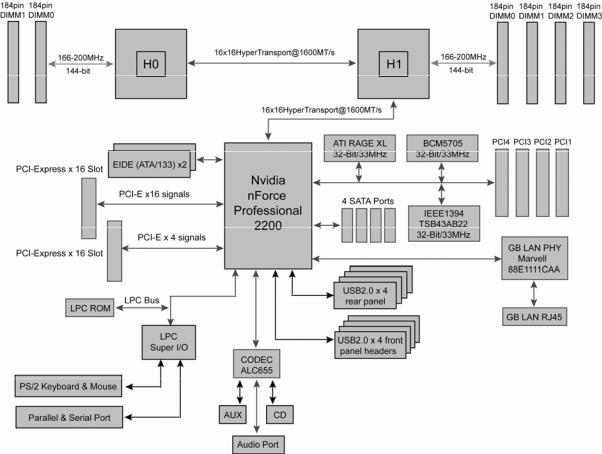
2.2 - Block Diagram
Tiger K8WE (S2877) Block Diagram
10 http://www.tyan.com
2.3 - Board Parts, Jumpers and Connectors
This diagram is representative of the latest board revision available at the time of publishing. The board you receive may not look exactly like the above diagram.
NOTE: * is only available on S2877ANRF version. ** is only available on S2877G2NR version.
11 http://www.tyan.com
Jumper Legend
|
|
OPEN - Jumper OFF, without jumper cover |
|
|
|
|||||
|
|
|
|
|
|
|
|
|
|
|
|
|
|
CLOSED – Jumper ON, with jumper cover |
|
|
|
||||
|
|
|
|
|
|
|
|
|||
Jumper/Connector |
|
|
Function |
|
|
Settings |
|
|||
|
|
|
|
|
|
|
|
|
|
|
|
|
J139 |
|
|
Front Panel Header |
|
|
See Section 2.3.1 |
|
|
|
|
|
|
|
|
|
|
|
|
|
|
|
J112 |
|
Clear CMOS Jumper |
|
See Section 2.3.2 |
|
|||
|
|
|
|
|
|
|
|
|||
|
|
J77 |
|
|
Chassis Intrusion Header |
|
|
See Section 2.3.3 |
|
|
|
|
|
|
|
|
|
|
|
|
|
|
|
*J147 |
|
FireWire (IEEE1394A) Disable |
|
See Section 2.3.4 |
|
|||
|
|
|
Jumper |
|
|
|||||
|
|
|
|
|
|
|
|
|
||
|
*J148/*J149 |
|
|
FireWire (IEEE 1394A) Pin |
|
|
See Section 2.3.5 |
|
||
|
|
|
Header |
|
|
|
||||
|
|
|
|
|
|
|
|
|
|
|
|
|
J14 |
|
Buzzer/ External Speaker |
|
See Section 2.3.6 |
|
|||
|
|
|
Header |
|
|
|||||
|
|
|
|
|
|
|
|
|
||
|
|
J42 |
|
|
COM2 Connector |
|
|
See Section 2.3.7 |
|
|
|
|
|
|
|
|
|
|
|
|
|
|
J25/J140 |
|
USB2.0 Front Panel Header |
|
See Section 2.3.8 |
|
||||
|
|
|
|
|
|
|
|
|||
|
|
J13 |
|
|
Keyboard Lock Connector |
|
|
See Section 2.3.9 |
|
|
|
|
|
|
|
|
|
|
|
|
|
|
|
J2 |
|
Marvell 88E1111 GbE LAN |
|
See Section 2.3.10 |
|
|||
|
|
|
Front Panel Header |
|
|
|||||
|
|
|
|
|
|
|
|
|
||
|
|
**J3 |
|
|
BCM5705 GbE LAN Front |
|
|
See Section 2.3.10 |
|
|
|
|
|
|
Panel Header |
|
|
|
|||
|
|
|
|
|
|
|
|
|
|
|
|
|
**J85 |
|
VGA Enable/Disable Jumper |
|
See Section 2.3.11 |
|
|||
|
|
|
|
|
|
|
|
|
|
|
|
|
**J152 |
|
|
BCM5705 LAN Enable/Disable |
|
See Section 2.3.12 |
|
||
|
|
|
|
Jumper |
|
|
||||
|
|
|
|
|
|
|
|
|
||
|
|
P51 |
|
CD_IN Connector |
|
|
|
|||
|
|
|
|
|
|
|
|
|||
|
|
P52 |
|
|
Audio Aux_IN Connector |
|
|
|
|
|
|
|
|
|
|
|
|
|
|
|
|
|
|
*P53 |
|
Front Audio Header |
|
See Section 2.3.13 |
|
|||
|
|
|
|
|
|
|
|
|||
|
|
J9 |
|
|
CPU1 Fan Connector (4pin) |
|
|
See Section 2.3.14 |
|
|
|
|
|
|
|
|
|
|
|
|
|
|
|
J37 |
|
CPU2 Fan Connector (4pin) |
|
See Section 2.3.14 |
|
|||
|
|
|
|
|
|
|
|
|||
|
|
J47 |
|
|
Chassis Fan Connector (4pin) |
|
|
See Section 2.3.15 |
|
|
|
|
|
|
|
|
|
|
|
|
|
|
|
J36/J10 |
|
Chassis Fan Connector (3pin) |
|
See Section 2.3.16 |
|
|||
|
|
|
|
|
|
|
|
|
|
|
|
|
J5 |
|
|
3-pin or 4-pin fan support |
|
|
See Section 2.3.17 |
|
|
|
|
|
|
selection Jumper |
|
|
|
|||
|
|
|
|
|
|
|
|
|
|
|
|
|
|
|
|
12 |
|
|
|
|
|
|
|
|
|
|
|
http://www.tyan.com |
|
|
|
|
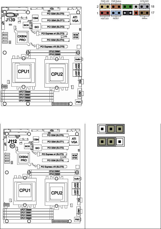
2.3.1 Front Panel Header: J139
|
|
|
|
|
|
|
|
|
|
|
|
|
|
|
|
|
|
|
|
|
|
|
|
|
|
|
|
|
|
|
|
|
|
|
|
|
|
|
|
Function |
|
PIN |
|
|
PIN |
|
Function |
|
|
||||
|
|
|
|
# |
|
|
# |
|
|
|
|
||||||
|
|
|
|
HDD LED+ |
|
|
1 |
|
|
|
2 |
|
|
PWR LED+ |
|
|
|
|
|
|
|
|
|
|
|
|
|
|
|
|
|
|
|
|
|
|
|
|
|
HDD LED- |
|
|
3 |
|
|
|
4 |
|
|
PWR LED- |
|
|
|
|
|
|
|
|
|
|
|
|
|
|
|
|
|
|
|
|
|
|
|
|
|
Reset |
|
|
5 |
|
|
|
6 |
|
|
PWR |
|
|
|
|
|
|
|
Button - |
|
|
|
|
|
|
|
Button+ |
|
|
|
||
|
|
|
|
|
|
|
|
|
|
|
|
|
|
|
|
||
|
|
|
|
Reset |
|
|
7 |
|
|
|
8 |
|
|
PWR |
|
|
|
|
|
|
|
Button + |
|
|
|
|
|
|
|
Button- |
|
|
|
||
|
|
|
|
|
|
|
|
|
|
|
|
|
|
|
|
||
|
|
|
|
VCC |
|
|
9 |
|
|
|
10 |
|
|
NC |
|
|
|
|
|
|
|
|
|
|
|
|
|
|
|
|
|
|
|
|
|
|
|
|
|
SMI |
|
|
11 |
|
|
|
12 |
|
|
GND |
|
|
|
|
|
|
|
|
|
|
|
|
|
|
|
|
|
|
|
|
|
|
|
|
|
5V_SB |
|
|
13 |
|
|
14 |
|
|
KEY |
|
|
||
|
|
|
|
|
|
|
|
|
|
|
|
|
|
|
|
|
|
|
|
|
|
SMB-DAT |
|
|
15 |
|
|
|
16 |
|
|
GND |
|
|
|
|
|
|
|
|
|
|
|
|
|
|
|
|
|
|
|
|
|
|
|
|
|
SMB-CLK |
|
|
17 |
|
|
|
18 |
|
|
Intruder# |
|
|
|
|
|
|
|
|
|
|
|
|
|
|
|
|
|
|
|
|
|
|
|
|
|
|
|
|
|
|
|
|
|
|
|
|
|
|
|
2.3.2 Clear CMOS Header: J112
|
Pin_3 |
Pin_1 |
Default |
|
|
||
|
|
|
|
|
Pin_3 |
Pin_1 |
Clear |
|
|
You can reset the CMOS settings by using this jumper if you have forgotten your system/setup password or need to clear system BIOS setting.
- Power off system and disconnect both power connectors from the motherboard
- Use jumper cap to close Pin_2 and Pin_3 for several seconds to Clear CMOS
- Put jumper cap back to Pin_1 and Pin_2 (default setting)
Reconnect power & power on system
13 http://www.tyan.com

2.3.3 Chassis Intrusion Header: J77
PIN2
PIN1
Pin-2
GND
Pin-1
INTRUDUER _L
The Chassis Intrusion Header provides chassis intrusionmonitoring function.
Note: For use with chassis that support this feature
2.3.4 *FireWire (IEEE1394A) Enable/Disable Jumper: *J147
Open
Closed
Use this jumper to enable/disable
IEEE1394.
Open : Enable (Default)
Closed : Disable
Note: J147 is only available on
S2877ANRF version.
14 http://www.tyan.com
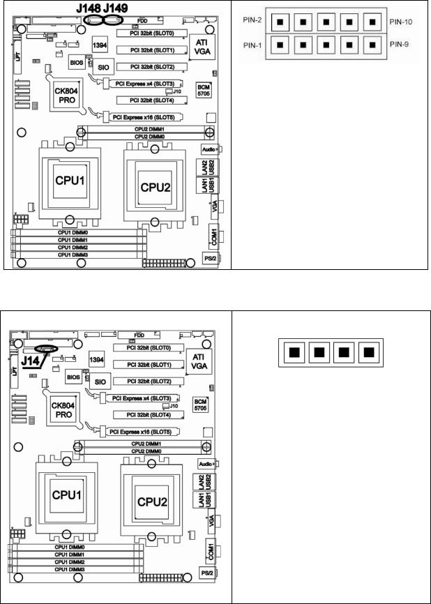
2.3.5 *FireWire (IEEE1394A) Pin Header: *J148/*J149
Signal |
Pin |
Pin |
Signal |
Description |
# |
# |
Description |
TPA+ |
1 |
2 |
TPA- |
GND |
3 |
4 |
GND |
TPB+ |
5 |
6 |
TPB- |
+12V |
7 |
8 |
+12V |
KEY |
9 |
10 |
GND |
Warning: Both 1394 header and 1394 cable connector are colored black in order to distinguish from USB header which is colored blue. Please be aware that incorrect installation may harm the device.
Note: J148 & J149 are only available on S2877ANRF version
2.3.6 Buzzer/External Speaker Header: J14
PIN1
|
Pin # |
Signal Description |
|
|
1 |
Speaker+ |
|
|
2 |
NC |
|
|
3 |
Buzzer- |
|
|
4 |
Speaker- |
|
Close Pin3 and Pin4 (Default)
Enable onboard buzzer
Open Pin3 and Pin4
Disable onboard buzzer or connect to chassis speaker
15 http://www.tyan.com

2.3.7 COM2 Connector: J42
|
Signal |
Pin |
|
Pin |
|
|
Signal |
|
Description |
# |
|
# |
|
|
Description |
|
|
|
|
|
|
|
|
|
Data-Carrier |
1 |
|
2 |
|
|
Data-Set- |
|
Detect |
|
|
|
Ready |
||
|
|
|
|
|
|
||
|
Receive-Data |
3 |
|
4 |
|
|
Request-to- |
|
|
|
|
Send |
|||
|
|
|
|
|
|
|
|
|
Transfer-Data |
5 |
|
6 |
|
|
Clear-to-Send |
|
|
|
|
|
|
|
|
|
Data- |
7 |
|
8 |
|
|
Ring-Indicator |
|
Terminal- |
|
|
|
|||
|
Ready |
|
|
|
|
|
|
|
Ground |
9 |
|
10 |
|
|
Key |
|
|
|
|
|
|
|
|
Use these pin definitions to connect a port to COM2.
2.3.8 USB 2.0 Front Panel Headers: J25/J140
Signal |
Pin |
Pin |
Signal |
Description |
# |
# |
Description |
VCC |
1 |
2 |
VCC |
USB DATA- |
3 |
4 |
USB DATA- |
USB DATA+ |
5 |
6 |
USB DATA+ |
GND |
7 |
8 |
GND |
KEY |
9 |
10 |
GND |
Warning: USB header is colored blue in order to distinguish from 1394 header. Both 1394 header and connector of 1394 cable are colored black. Please be aware that incorrect installation may harm the device.
Note: Use these headers to connect to chassis front panel USB connectors.
16 http://www.tyan.com
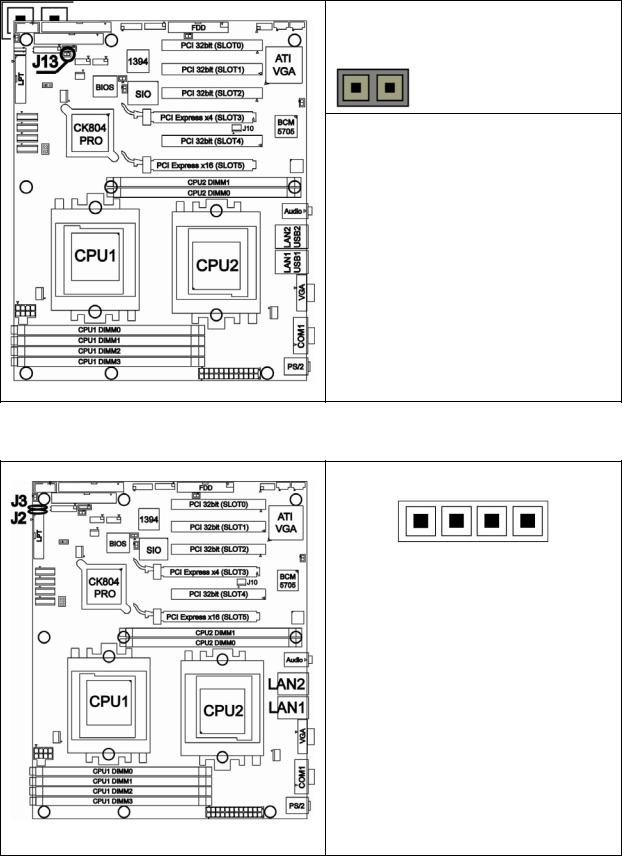
2.3.9 Keyboard Lock Connector: J13
Open
Closed
Use this Jumper to enable/disable
PS/2 keyboard.
Open : Enable (Default)
Closed : Disable
2.3.10 Gigabit LAN1/**LAN2 Front Panel Header: J2/ **J3
PIN1
|
Pin # |
Signal Description |
|
|
|
|
|
|
1 |
1000Mb+/100Mb-_Link |
|
|
2 |
1000Mb-/100Mb+_Link |
|
|
3 |
Active- |
|
|
4 |
Active+ |
|
Use this 4-Pin Header to connect
LAN LED on Front Panel.
Note: J3 is only available on
S2877G2NR version.
17 http://www.tyan.com
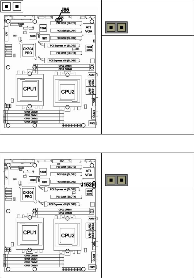
2.3.11 **VGA (ATI Rage XL) Enable/ Disable Jumper: **J85
Open
Closed
Use this Jumper to enable/disable onboard ATI Rage XL graphic.
Open : Enable (Default) Closed : Disable
Note: J85 is only available on
S2877G2NR version.
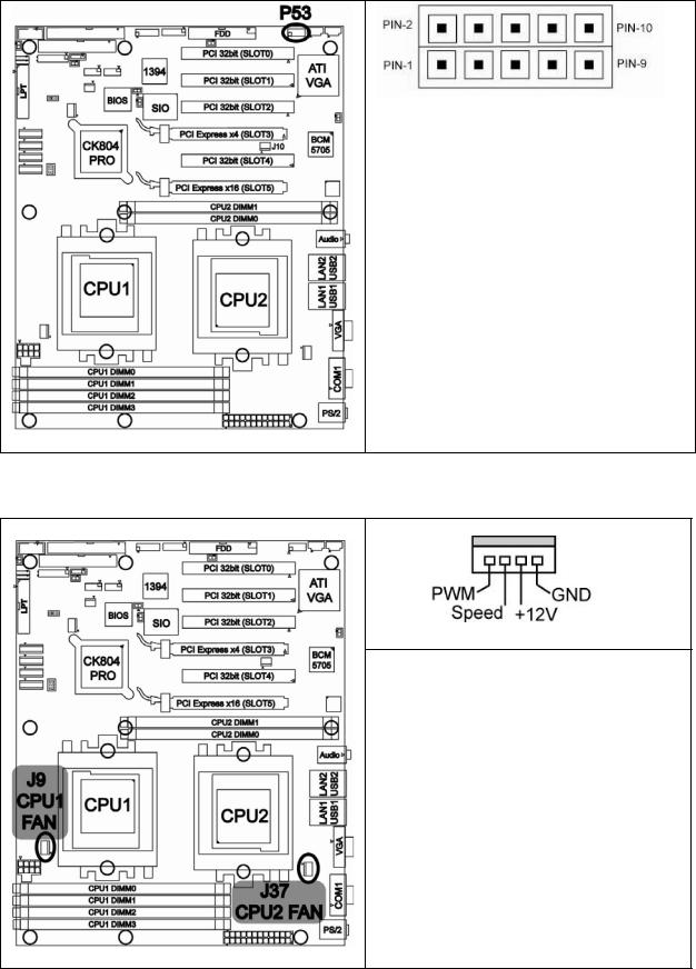
2.3.12 **BCM5705 Gigabit LAN Enable/ Disable Jumper: **J152
Open
Closed
Use this Jumper to enable/disable
LAN2 (BCM5705 GbE LAN)
Open : Enable (Default)
Closed : Disable
Note: J152 is only available on
S2877G2NR version.
18 http://www.tyan.com
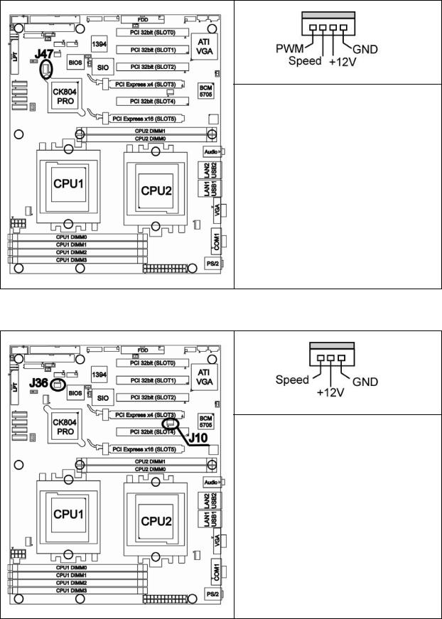
2.3.13 *Front Panel Audio Header: *P53
Signal |
Pin |
Pin |
Signal |
Description |
# |
# |
Description |
|
|
|
|
AUD_MIC_L |
1 |
2 |
GND |
|
|
|
|
AUD_MIC_R |
3 |
4 |
AVDD |
|
|
|
|
AUD_FP_R |
5 |
6 |
AUD_RET_R |
|
|
|
|
NC |
7 |
8 |
KEY |
|
|
|
|
AUD_FP_L |
9 |
10 |
AUD_RET_L |
|
|
|
|
Note: If you use onboard Audio port, you must close Pin5-Pin6 and Pin9-Pin10. P53 is only available on S2877ANRF version.
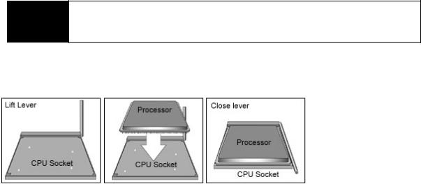
2.3.14 CPU FAN Connector: J9/J37
PIN1
Use these connectors to connect processor cooling fans to your motherboard.
J9 for CPU1 & J37 for CPU2.
This 4-pin fan connector supports a new standard fan with integrated fan speed control on the fan itself for better fan life.
19 http://www.tyan.com
2.3.15 Chassis 4-pin FAN Connector: J47
PIN1
Use this connector to connect chassis cooling fan to your motherboard.
This 4-pin fan connector supports a new standard fan with integrated fan speed control on the fan itself for better fan life.
2.3.16 Chassis 3-pin FAN Connectors: J36/J10
PIN1
Use these connectors to connect chassis cooling fans to your motherboard.
The traditional 3-pin fan connector does not have PWM fan speed control function.
20 http://www.tyan.com
2.3.17 3-pin or 4-pin fan support selection jumper: J5
|
|
Signal |
|
Pin |
|
Pin |
|
|
|
Signal |
|
|||
|
Description |
|
# |
|
# |
|
|
Description |
|
|||||
|
|
|
|
|
|
|
|
|
|
|
|
|
|
|
|
|
GND |
|
6 |
|
5 |
|
SYS_FAN_PWM |
||||||
|
|
|
|
|
|
|
|
|
|
|
|
|
|
|
|
|
GND |
|
4 |
|
3 |
|
CPU2_FAN_PWM |
||||||
|
|
|
|
|
|
|
|
|
|
|
|
|
|
|
|
|
GND |
|
2 |
|
1 |
|
CPU1_FAN_PWM |
||||||
|
|
|
|
|
|
|
|
|
|
|
|
|
|
|
|
|
|
|
|
|
|
|
|
|
|
||||
|
|
Pin # |
|
|
Corresponding |
|
|
FAN |
|
|
||||
|
|
|
|
|
|
FAN |
|
|
Connector |
|
|
|||
|
|
|
|
|
|
|
|
|
|
|
||||
|
|
|
|
|
|
|
|
|
|
|
|
|
|
|
|
1 & 2 |
|
|
|
CPU1 FAN |
|
|
J9 |
|
|||||
|
|
|
|
|
|
|
|
|
|
|||||
|
3 & 4 |
|
|
|
CPU2 FAN |
|
|
J37 |
|
|||||
|
|
|
|
|
|
|
|
|
|
|||||
|
5 & 6 |
|
|
|
Chassis FAN |
|
|
J47 |
|
|||||
|
|
|
|
|
|
|
|
|
|
|
|
|
|
|
Open: To support 3-pin auto fan
Closed (Default): To support 4-pin auto fan
21 http://www.tyan.com
2.4 - Installing the Processor(s)
Your brand new Tiger K8WE supports the latest 64-bit processor technology from AMD. Only AMD Opteron™ processor 200 series are certified and supported with this motherboard.
Check our website for latest processor support. http://www.tyan.com
If using a single processor, it MUST be installed in socket NOTE CPU1. When using a single processor only CPU1 memory
banks are addressable.
TYAN is not liable for damage as a result of operating an unsupported configuration.
The diagram is provided as a visual guide to help you install socket processors and may not be an exact representation of the processors you have.
Step 1: Lift the lever on the socket until it is approximately 90o or as far back as possible to the socket.
Step 2: Align the processor with the socket. There are keyed pins underneath the processor to ensure that the processor’s installed correctly.
Step 3: Seat the processor firmly into the socket by gently pressing down until the processor sits flush with the socket.
Step 4: Place the socket lever back down until it locks into place. The installation is finished.
Repeat these steps for the second processor if you are using two processors.
Take care when installing processors as they have very fragile connector pins below the processor and can bend and break if inserted improperly.
22 http://www.tyan.com
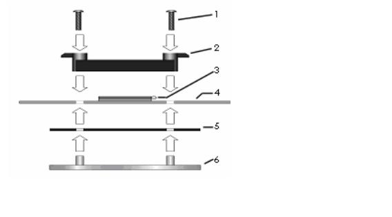
2.5 - Heatsink Retention Frame Installation
After you are done installing the processor(s), you should proceed to installing the retention frame and heatsink. The CPU heatsink will ensure that the processors do not overheat and continue to operate at maximum performance for as long as you own them. Overheated processors are also dangerous to the motherboard.
The backplate assembly prevents excessive motherboard flexing in the area near the processor and provides a base for the installation of the heatsink retention bracket and heatsink.
Because there are many different types of heatsinks available from many different manufacturers, a lot of them have their own method of installation. For the safest method of installation and information on choosing the appropriate heatsink, use heatsinks validated by AMD. Please refer to AMD’s website at www.amd.com.
The following diagram will illustrate how to install the most common CPU back plates:
1. Mounting screws
2. Heatsink retention frame
3. CPU socket
4. Motherboard PCB
5. Adhesive insulator material
6. Backplate assembly
NOTE: Please see next section for specific instructions on how to install mounting bracket.
23 http://www.tyan.com
 Loading...