

Tyan THUNDER N6650EX S4992 User Manual

S4992
///
Version 1.0
S4992
Copyright
Copyright © MiTAC International Corporation, 2008. All rights reserved. No part
of this manual may be reproduced
or translated without prior written consent from MiTAC International Corporation.
Trademark
All registered and unregistered trademarks and company names contained in
this manual are property of their respective owners including, but not limited to
the following.
TYAN®, is trademarks of MiTAC International Corporation.
AMD® ,Opteron™, and combinations thereof are trademarks of AMD
Corporation.
AMI®, AMIBIOS®, and combinations thereof are trademarks of AMI
Technologies.
Microsoft®, Windows® are trademarks of Microsoft Corporation.
Nvidia® and nForce® are trademarks of Nvidia Corporation.
IBM®, PC®, AT®, PS/2® are trademarks of IBM Corporation.
Winbond® is a trademark of Winbond Electronics Corporation.
Notice
Information contained in this document is furnished by MiTAC International
Corporation and has been reviewed for accuracy and reliability prior to printing.
MiTAC assumes no liability whatsoever, and disclaims any express or implied
warranty, relating to sale and/or use of TYAN
warranties relating to fitness for a particular purpose or merchantability. MiTAC
retains the right to make changes to product descriptions and/or specifications
at any time, without notice. In no event will MiTAC be held liable for any direct
or indirect, incidental or consequential damage, loss of use, loss of data or other
malady resulting from errors or inaccuracies of information contained in this
document.
®
products including liability or


Contents
Before you begin Ⅴ
Chapter 1: Instruction 1
1.1 Congratulations .......................................................................................1
1.2 Hardware Specifications.......................................................................... 1
1.3 Software Specifications ...........................................................................2
Chapter 2: Board Installation 3
2.1 Board Image ............................................................................................ 4
2.2 Block Diagram ......................................................................................... 5
2.3 Board Parts, Jumpers and Connectors.................................................... 6
2.4 Installing the Processor .........................................................................18
2.5 Heat sink Installation .............................................................................19
2.6 Thermal Interface Material..................................................................... 20
2.7 Finishing Installing the Heat sink ...........................................................21
2.8 Tips on Installing Motherboard in Chassis ............................................. 22
2.9 Installing the Memory ............................................................................24
2.10 Attaching Drive Cables ........................................................................ 27
2.11 Installing Add-In Cards ........................................................................28
2.12 Connecting External Devices............................................................... 29
2.13 Installing the Power Supply .................................................................30
2.14 Finishing Up.........................................................................................32
Chapter 3: KVM-over-IP Server Management 33
3.1 Overview of KVM-over-IP Sever Management..................................... 33
3.2 Key Feature.......................................................................................... 33
3.3 Initialize and Web Interface ..................................................................34
3.4 Configuration ........................................................................................ 37
3.5 Menu Option ......................................................................................... 45
3.6 Notes ....................................................................................................80
Chapter 4: BIOS Setup 85
4.1 About the BIOS..................................................................................... 85
4.2 BIOS Menu Bar ....................................................................................85
4.3 Setup Basics......................................................................................... 86
4.4 Getting Help..........................................................................................86
4.5 In Case of Problems ............................................................................. 86
4.6 BIOS Main Menu .................................................................................. 87
4.7 BIOS Advanced Menu .......................................................................... 88
4.8 PCI PnP Menu....................................................................................107
4.9 Boot Menu .......................................................................................... 109
4.10 Security Menu.................................................................................... 113
4.11 Chipset Menu ....................................................................................114
4.12 Exit Menu........................................................................................... 127

Chapter 5: Diagnostics 129
5.1 Beep Codes......................................................................................... 129
5.2 Flash Utility .......................................................................................... 129
5.3 AMIBIOS Post Code............................................................................130
Appendix: How to Make a Driver Diskette 133
Glossary 135
Technical Support 141
Before you begin…
Check the box contents!
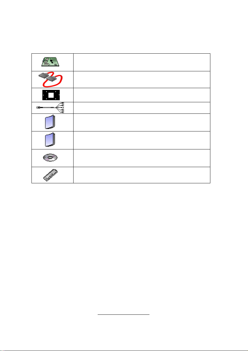
The retail motherboard package should contain the following:
1x S4992 Motherboard
6 x SATA Cable
4 x CPU Backplane
2 x SAS to Backplane Cable
1 x S4992 User’s Manual
1 x S4992 Quick Reference Guide
®
1 x TYAN
Driver CD
1 x I/O Shield
If any of these items are missing, please contact your vendor/dealer for
replacement before continuing with the installation process.
V
http://www.TYAN.com


Chapter 1: Instruction
1.1 - Congratulations
You have purchased one of the most powerful server solutions. Based on
Nvidia® NPF3600 and NPF3050 chipsets, S4992 is designed to support AMD®
Opteron™ Rev. F 8000 series Dual-core and Quad-core processors and up to
128GB DDRII-400/533/667/800 memory, providing a rich feature set and
incredible performance. Leveraging advanced technology from AMD
®
, S4992 is
capable of offering scalable 32 and 64-bit computing, high-bandwidth memory
design, and lightning-fast PCI-E, PCI-X bus implementation.
S4992 not only empowers your company in today’s demanding IT environment
but also offers a smooth path for future application usage. TYAN
®
is also proud
to deliver S4992 in SAS and SATA II flavor. All of this provides S4992 the
power and flexibility to meet the needs of nearly any server application.
Remember to visit TYAN®’s Website at http://www.TYAN.com. There you can
find information on all of TYAN
®
’s products with FAQs, online manuals and
BIOS upgrades.
1.2 - Hardware Specifications
Processors
● Four 1207-pin ZIF socket
● Supports up to four AMD®
Opteron™ Rev. F 8000 series
Dual Core/ Quad-core processors
(Barcelona/Shanghai)
● HyperTransport™ link bandwidth
between processors varies from
2.0GT/s up to 4.4GT/s, depending
on processor populated
● Four onboard 5-phase VRDs (four
phases for CPU-core and one
phase for North bridge)
Chipset
● nVidia
● PERICOM
®
nForce® Pro 3600+
®
nForce® Pro 3050
nVidia
®
PI7C9X130 PCI-E
bridge
● HW monitors:
(1) WinbondW83793G
(2) ADT7476
Expansion Slots
● (2) PCI-E slots with x16 signal
(1) x 8 or x16 signal from MCP55
(1) x 8 or x16 signal from IO55
● (3) PCI-E slots with x8 signal
(1) x 8 signal from MCP55
(1) x 8 signal from IO55
(1) x 8 signal from IO55
● (1) PCI-X 133MHz slots from
PERICOM PI7C9X130 (through
IO55)
System Management
● Raritan KIRA100 chip w/ iKVM (M3
type)
Onboard SAS Controller
● LSI 1068E SAS controller
● (8) SAS ports
● RAID 0,1,1E support
1
http://www.TYAN.com

Memory
● Dual-channel memory bus
● 32 x 240-pin 1.8-volt DDRII DIMM
sockets (eight on each CPU)
● Maximum of 256GB DDRII-
400/533/667/800 (4 DIMM per
CPU; 2 DIMM per Channel can
run DDRII-800)
● Supports ECC Registered DIMMs
Integrated I/O
● (2) USB 2.0 headers (two ports in
one header)
● (6) SATAII connectors from
MCP55
● (8) SAS ports (2 four-in-one
connectors) from LSI 1068E
● (2) RJ-45 10/100/1000 LAN ports
from 82571
(1) RJ-45 10/100 LAN port from
onboard Raritan KIRA100 chip
w/ iKVM(M3 type)
● (10) 4-pin FAN headers with
autofan and tachmeter function
● (1) 2x9-pin front panel header
● (1) 2x6-pin TYFP2 header
● (1) 2x9-pin FAN header for
Barebone
● (1) 2x3-pin LCM header
Back Panel I/O Connector
● Stacked connector for PS/2
®
Integrated Network Processor
● GbE Intel 82571 (2x GbE ports)
● Davicom DM9161AE (PHY) for
onboard Raritan KIRA100 chip w/
iKVM (M3 type) (LAN3 <SMDC
dedicated only> MAC is integrated
in KIRA100)
● WOL and PXE support
● (3) RJ-45 ports with LEDs
Integrated 2D PCI Graphics
● XGI Z9S
● PCI interface
● 32MB DDRII frame buffer memory
BIOS
● AMIBIOS
ROM
®
on 8Mbit LPC Flash
Form Factor
● MEB (13”x 16.2”)
● PCB layer:10-layer
Power
● EPS12V
● (1) 24-pin,3V+5V+12V power
connector
● (2) 8-pin,12V power connector
● (1) 4-pin,12V power connector
Regulatory
● FCC Class B (DoC)
● European Community CE (DoC)
keyboard and mouse
● Stacked connector for (2) USB 2.0
● Stacked connector for VGA+COM
●(3) RJ-45 connectors, side by side
1.3 - Software Specifications
For OS (operation system) support, please check with TYAN support for latest
information.
2
http://www.TYAN.com

Chapter 2: Board Installation
You are now ready to install your motherboard.
How to install our products right… the first time
The first thing you should do is reading this user’s manual. It contains important
information that will make configuration and setup much easier. Here are some
precautions you should take when installing your motherboard:
(1) Ground yourself properly before removing your motherboard from the
antistatic bag. Unplug the power from your computer power supply and
then touch a safely grounded object to release static charge (i.e. power
supply case). For the safest conditions, TYAN® recommends wearing
a static safety wrist strap.
(2) Hold the motherboard by its edges and do not touch the bottom of the
board, or flex the board in any way.
(3) Avoid touching the motherboard components, IC chips, connectors,
memory modules, and leads.
(4) Place the motherboard on a grounded antistatic surface or on the
antistatic bag that the board was shipped in.
(5) Inspect the board for damage.
The following pages include details on how to install your motherboard into your
chassis, as well as installing the processor, memory, disk drives and cables.
NOTE
DO NOT APPLY POWER TO THE BOARD IF IT HAS BEEN
DAMAGED.
3
http://www.TYAN.com
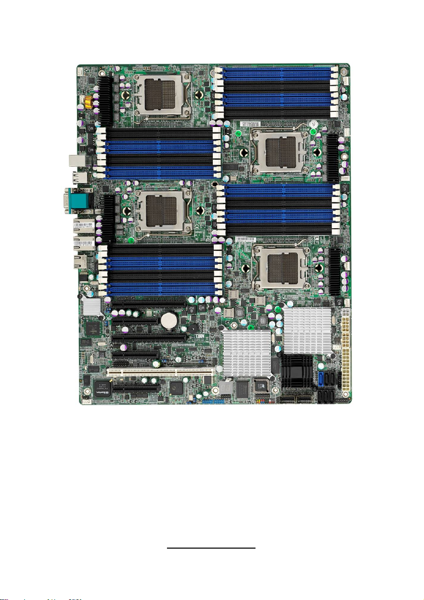
2.1- Board Image
This picture is representative of the latest board revision available at
the time of publishing. The board you receive may or may not look
exactly like the above picture.
4
http://www.TYAN.com
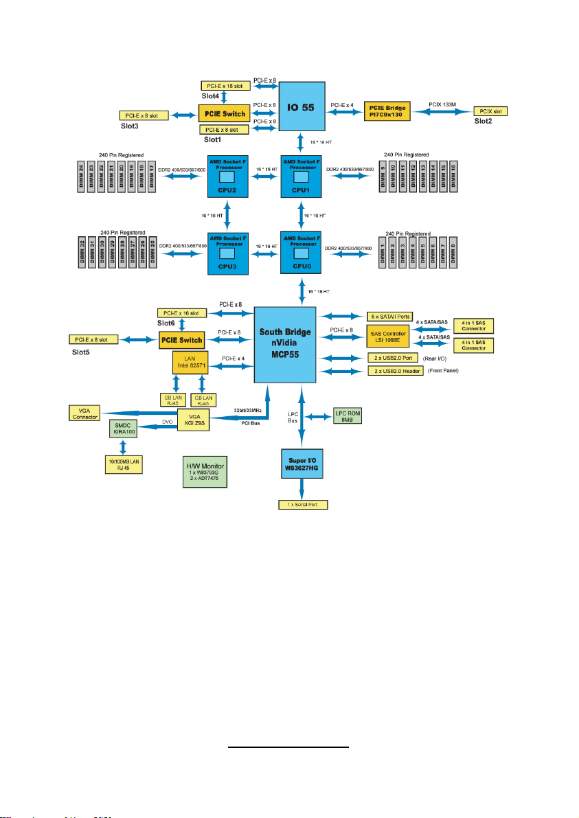
2.2 - Block Diagram
S4992 Block Diagram
Note: CPU1 is required to use PCI-E/PCI-X under IO55.
5
http://www.TYAN.com
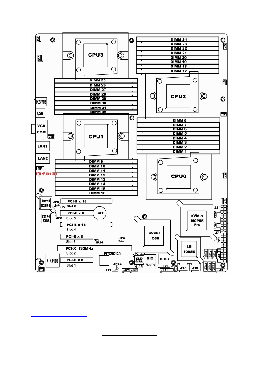
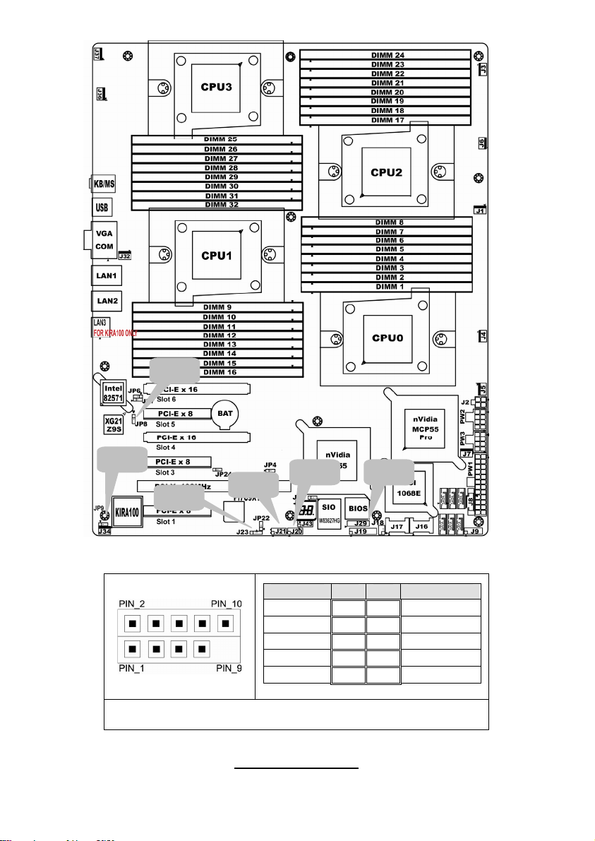
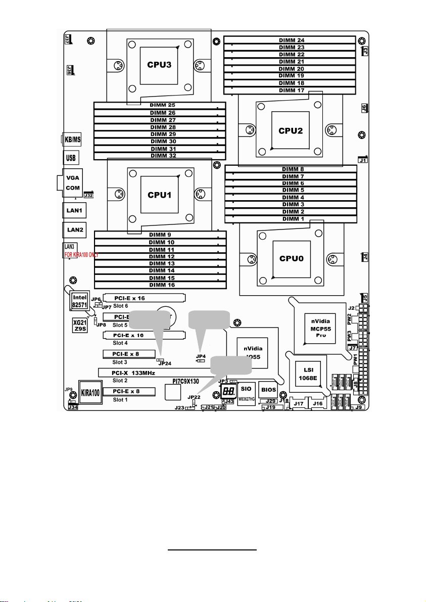
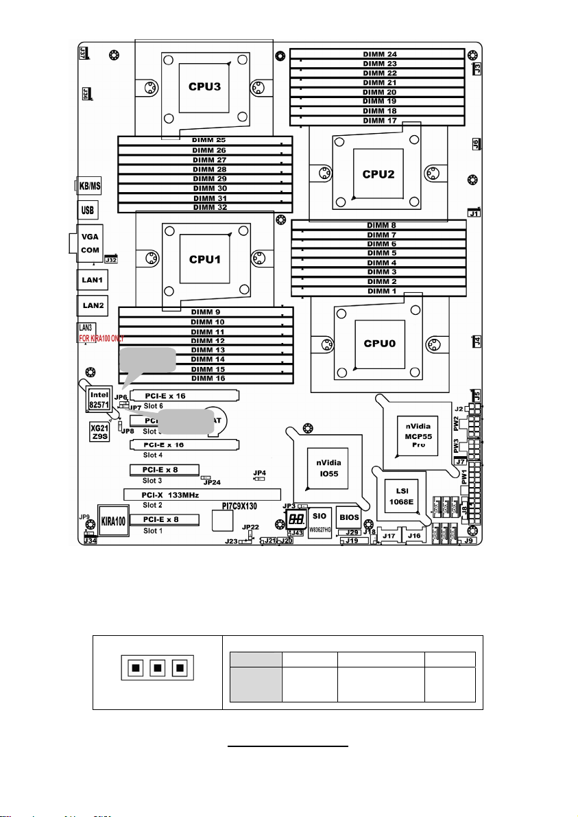
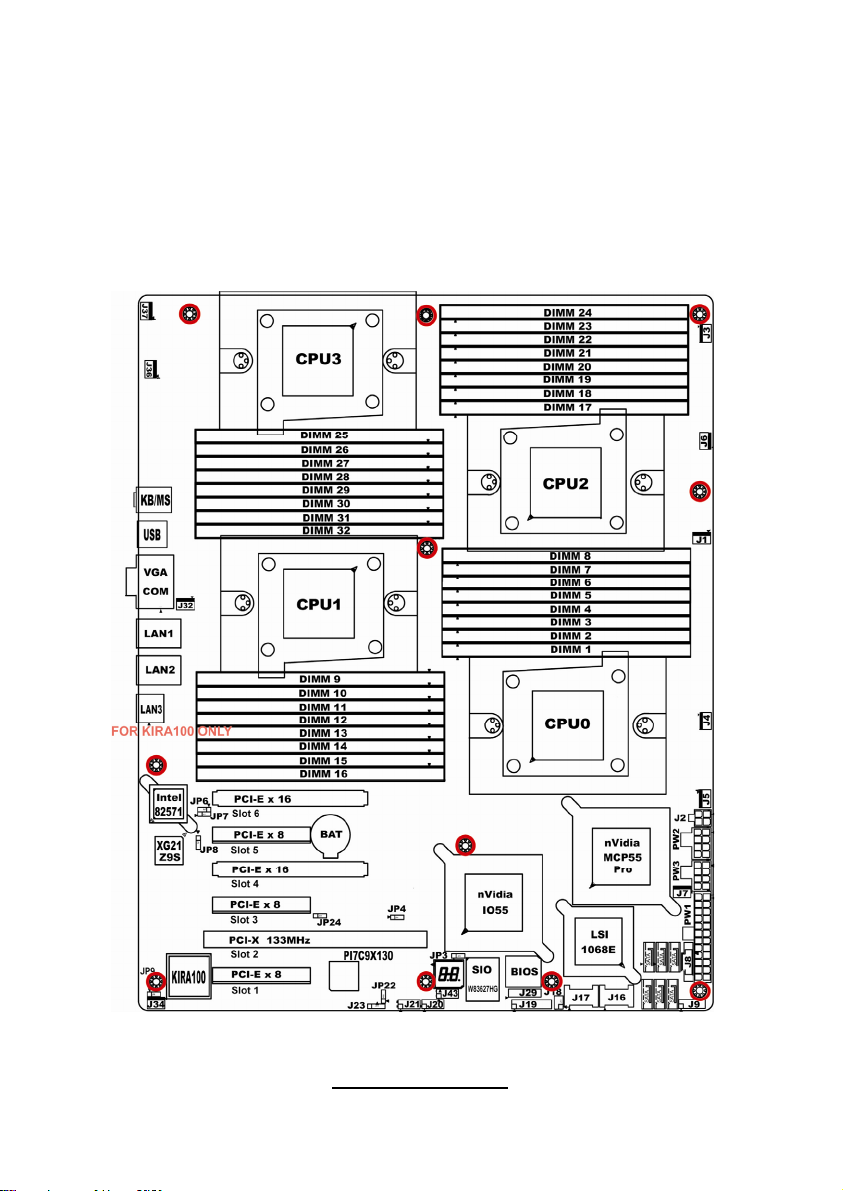
2.3 - Board Parts, Jumpers and Connectors
Note: Slot1-4 belong to IO55 and Slot5-6 belong to MCP55.
This diagram is representative of the latest board revision available at the time
of publishing. The board you receive may not look exactly like the above
diagram. But for the DIMM number please refer to the above placement for
memory installation. For the latest board revision, please visit:
http: //www.TYAN.com
http://www.TYAN.com
6
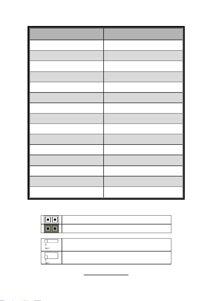
Jumpers & Connectors
Jumper/Connector Function
J1/J3/J4/J5/J6/J7/J32/J34/J36/J37 Fan connector
J8 PSMI Header
J9
J18 LCM Header
J19 Front Panel Header
J20/J21 USB 2.0 Header
J23 PCI-X Mode Selection
J29 BBU Fan Connector
JP3 Clear CMOS
JP6 LAN 2 Selection
JP7 LAN 1 Selection
JP8
JP9 IPMB Pin Header
Front Panel Header for
Barebones System
XG21 VGA Enable/Disable
Jumper
JP4/JP24 PCI-E configuration selection
JP22
Jumper Legend
OPEN - Jumper OFF Without jumper cover
CLOSED - Jumper ON With jumper cover
To indicate the location of pin-1
To indicate the location of pin-1
http://www.TYAN.com
PCI-X clock frequency 133/100
MHz selection
7
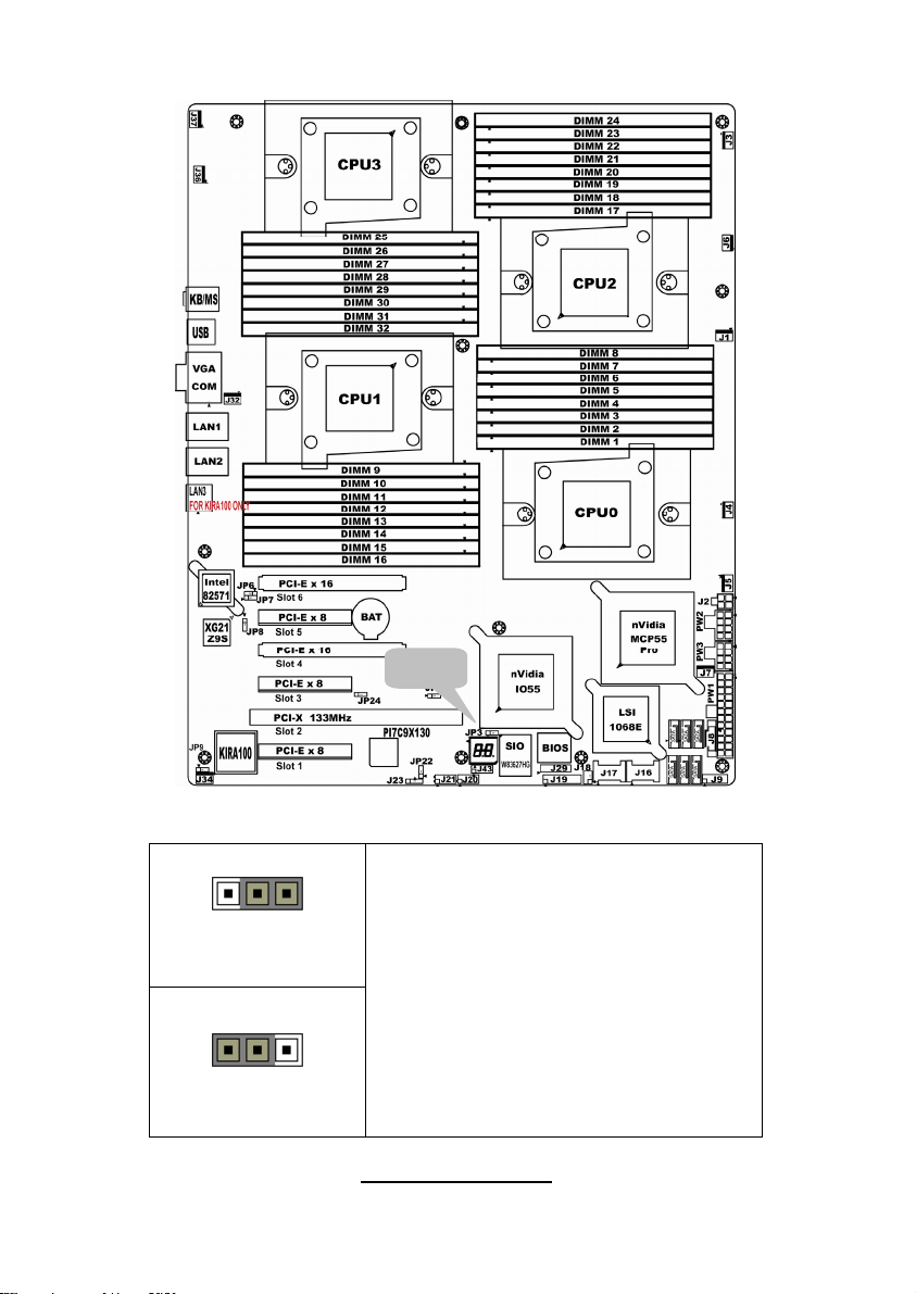
Jumper Placement
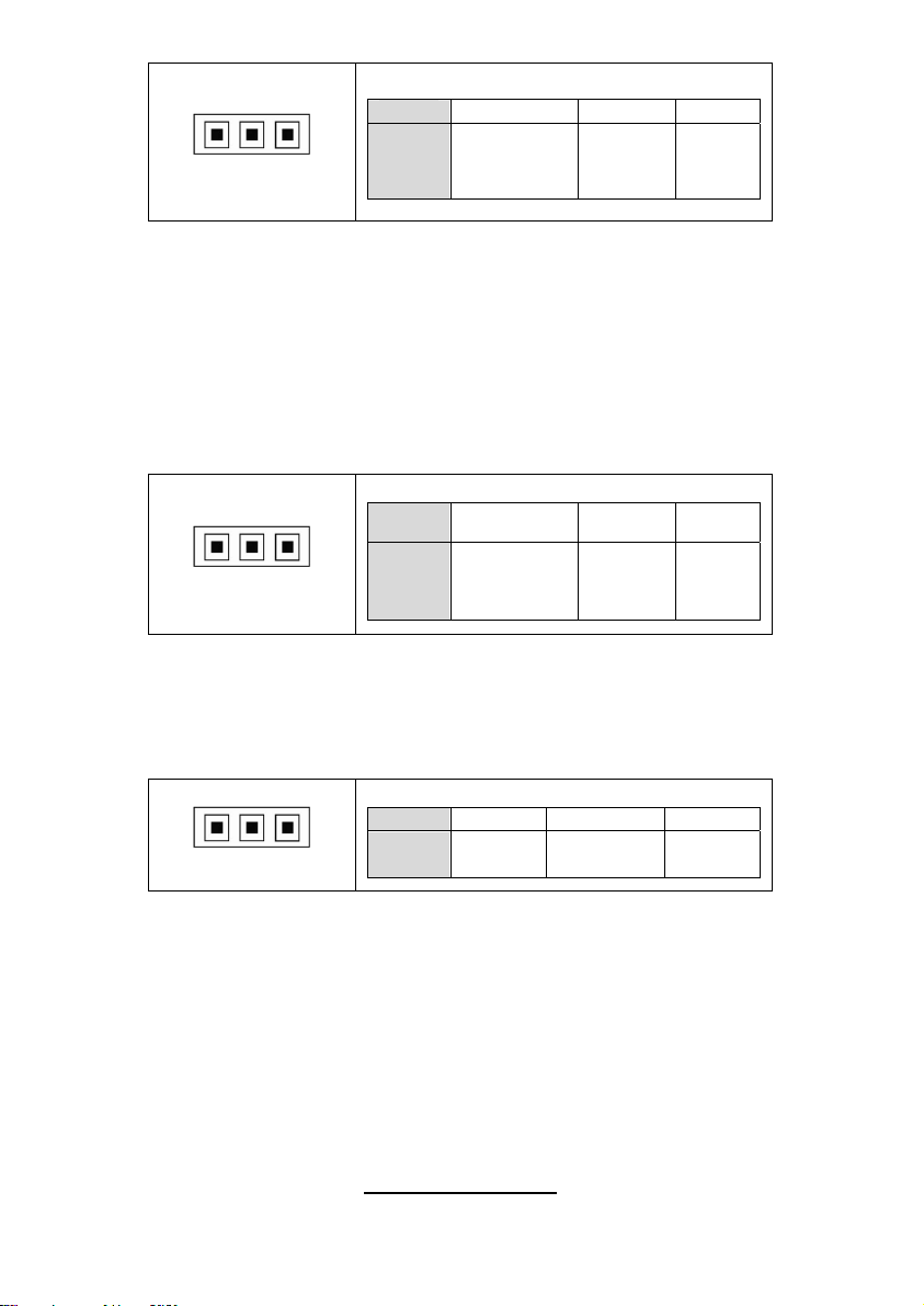
JP3
JP3: Clear CMOS
Pin_3 Pin_1
Pin_3 Pin_1
Clear CMOS
Normal
(Default)
You can reset the CMOS settings by using
this jumper if you have forgotten your
system/setup password or need to clear
system BIOS setting.
- Power off system and disconnect
both power connectors from the
motherboard
- Put jumper cap back to Pin_1 and
Pin_2 (default setting)
- Use jumper cap to close Pin_2 and
Pin_3 for several seconds to Clear
CMOS
Reconnect power & power on system
8
http://www.TYAN.com
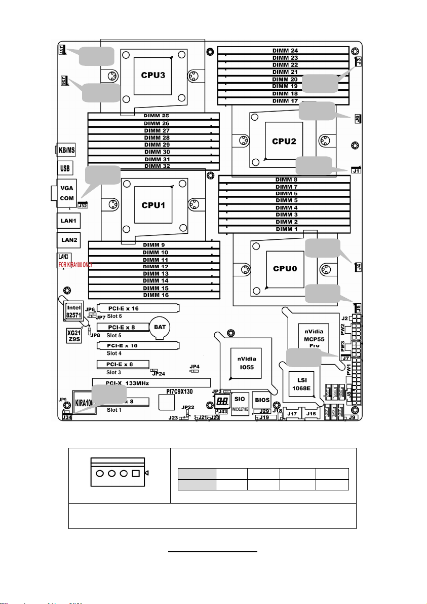
J37
J36
J32
J3
J6
J1
J4
J5
J7
J34
J1/J3/J4/J5/J6/J7/J32/J34/J36/J37: 4-pin fan connector
Pin 1 2 3 4
Pin_1
Signal
GND +12V TACH PWM
NOTE: When using the 3-pin fans, you will have no auto fan
functionality.
9
http://www.TYAN.com
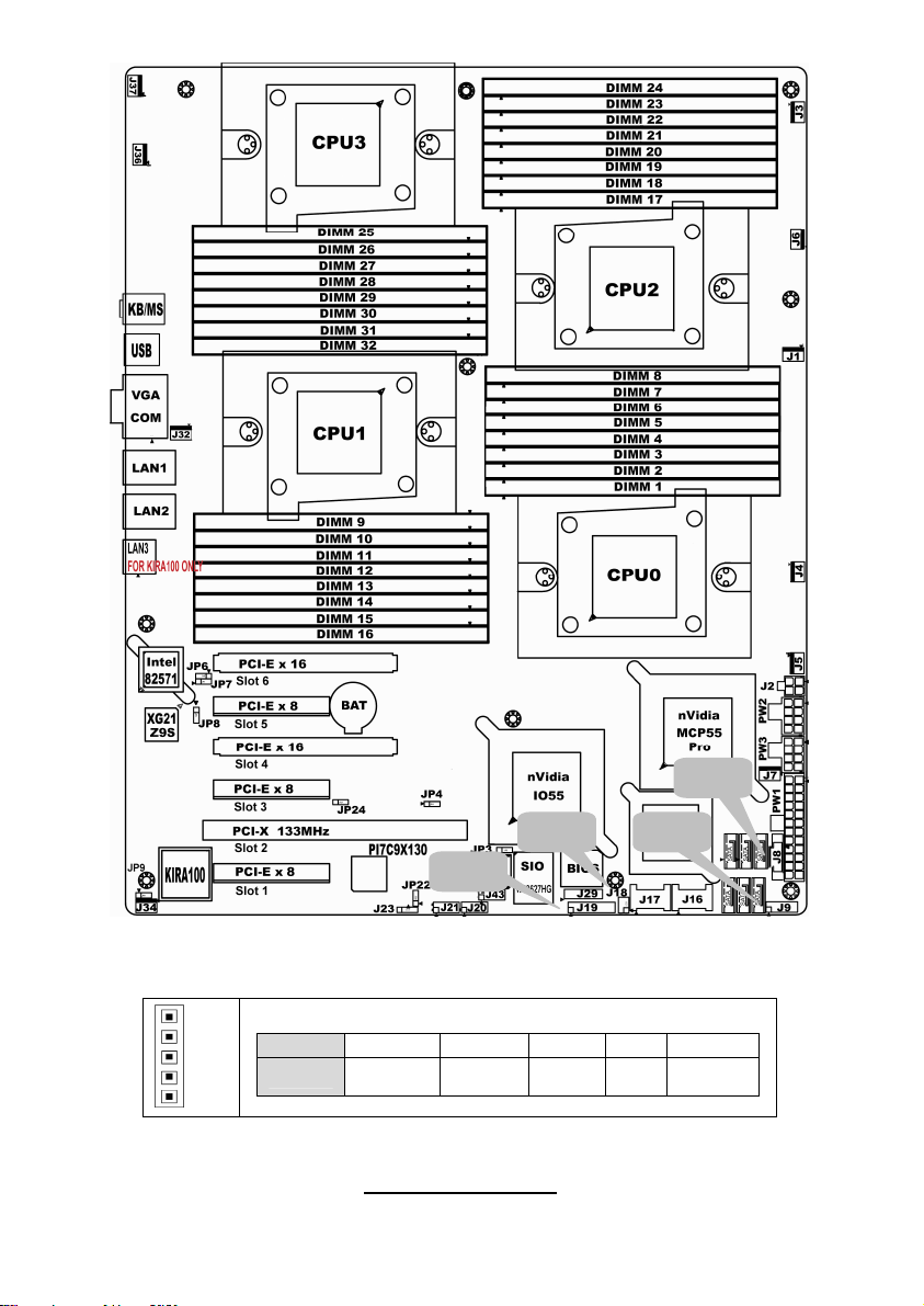
J8: PSMI Header
Pin_1
J8
J18 J9
J19
Pin 1 2 3 4 5
Signal
SMBUS
CLOCK
SMBUS
DATA
RSVD
(NC)
GND VDD_3P
3_DUAL
10
http://www.TYAN.com
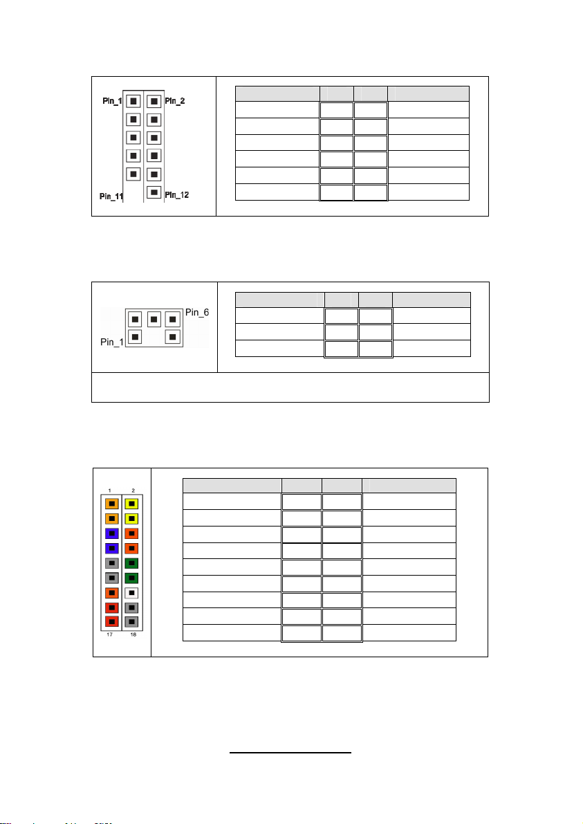
J9: Front panel Header for Barebones Systems
Signal Pin Pin Signal
LAN1_LED+ 1 2 LAN1_LEDLAN2_LED+ 3 4 LAN2_LEDLAN3_LED+ 5 6 LAN3_LED-
ID_LED+ 7 8 ID_LEDID_S/W+ 9 10 ID_S/W-
Key 11 12 RSVD
J18: LCM Pin Header
Signal Pin Pin Signal
VCC_5_RUN 1 2 RXD
KEY PIN 3 4 GND
VCC_5_ALW 5 6 TXD
Use this header to connect to the LCM module with system
monitoring function.
J19: Front Panel Header Connector
Signal Pin Pin Signal
HD LED+ 1 2 PW_LED+
HD_LED- 3 4 PW LED-
GND 5 6 P_S/W
RESET 7 8 GND
GND 9 10 FANFAIL_H
EXT_NMI 11 12 FANFAIL_L
5VSB 13 14 Key
SDA 15 16 GND
SCL 17 18 INTRUDER_L
11
http://www.TYAN.com
JP8
JP9
J20
J29
J21
J23
J20/J21: USB Pin Header
Signal Pin Pin Signal
+5VPWR 1 2 +5VPWR
USB0- 3 4 USB1-
USB0+ 5 6 USB1+
GND 7 8 GND
KEY PIN 9 10 GND
Use this header to connect to the USB devices via the provided
USB cable.
12
http://www.TYAN.com
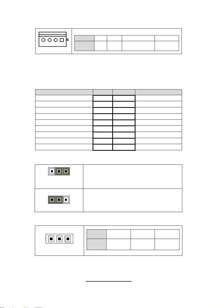
J23: PCI-X Mode Selection Header
Pin 1 2 3 4
Pin_1
Signal
N/C GND PCI_PCIXCAP
PCI Mode = Pins 2-3
PCI-X 66Mhz = Pins 3-4
PCI-X 100/133Mhz = Pins 1-2 (Default)
J29: BBU Fan Connector
Signal Pin Pin Signal
SYS1_TACH 1 2 SYS6_TACH
SYS2_TACH 3 4 SYS7_TACH
SYS3_TACH 5 6 SYS8_TACH
SYS4_TACH 7 8 SYS9_TACH
SYS5_TACH 9 10 SYS10_TACH
GND 11 12 KEY PIN
SYS2_PWM 13 14 CPUX_PWM
SYS11_TACH 15 16 SYS13_TACH
SYS12_TACH 17 18 SYS14_TACH
JP8: XG21 VGA Enable/Disable Jumper
10k TO
GROUND
Pin_3 Pin_1
Normal
(Default)
Pin_3 Pin_1
JP9: IPMB Pin Header
Pin_1
Pin_1 & Pin_2 closed: default setting
Pin_2 & Pin_3 closed: disable XG21
Pin 1 2 3
Signal
IPMB
DATA
GND
IPMB
CLK
13
http://www.TYAN.com
JP4JP24
JP22
JP4: PCI-E Configuration Selection
Pins 1-2 (Default):
If a x16 speed card is installed in slot 4, then the card installed will run at x16 speed
and slot 3 will be disabled.
If a x8 (or lower) card is installed on Slot 4, then the installed card will run at x8 (or
lower) speed and slot 3 will be active and run at a maximum of x8 speeds.
Pins 2-3:
If this jumper is set to pins 2 -3, then both slot 3 and 4 will be locked at x8 speed for
both slots regardless of the speed of card installed.
14
http://www.TYAN.com
Pin 1 2 3
Pin_1
Signal
PCIEX16
DETECT_L
IO55
PEMOD
SEL_L
NC
JP24: PCI-E Configuration Selection
Pins 1-2 (Default):
If a x16 speed card is installed in slot 6, then the card installed will run at x16 speed
and slot 5 will be disabled.
If a x8 (or lower) card is installed on Slot 6, then the installed card will run at x8 (or
lower) speed and slot 5 will be active and run at a maximum of x8 speeds.
Pins 2-3:
If this jumper is set to pins 2 -3, then both slot 5 and 6 will be locked at x8 speed for
both slots regardless of the speed of card installed.
Pin 1 2 3
Pin_1
Signal
MCP_X16
DETECT_L
MCP55
PEMOD
SEL_L
NC
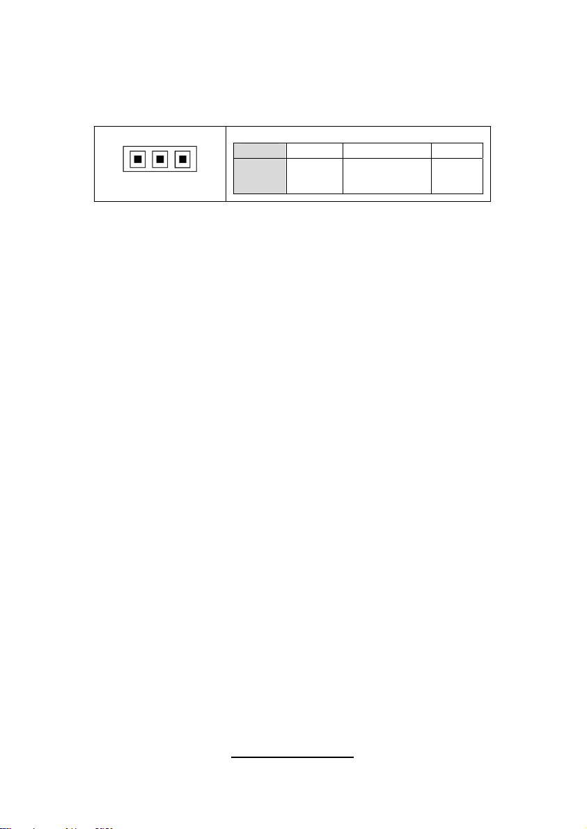
JP22: PCI-X Clock Frequency 133/100 MHz Selection
Pins 1-2 (Default): 133MHz
Pins 2-3: 100MHz
Pin 1 2 3
Pin_1
Signal
1k to
GND
S_SEL100
1k to
3.3V
15
http://www.TYAN.com
JP6
JP7
JP6: LAN2 Selection
Pins 1-2 (Default): Enable LAN2
Pins 2-3: Disable LAN2
Pin_1
Pin 1 2 3
Signal
http://www.TYAN.com
LAN1
DIS_N
16
82571_LAN1
DIS_N
GND
JP7: LAN1 Selection
Pins 1-2 (Default): Enable LAN1
Pins 2-3: Disable LAN1
Pin_1
Pin 1 2 3
Signal
LAN0
DIS_N
82571_LAN0
DIS_N
GND
17
http://www.TYAN.com
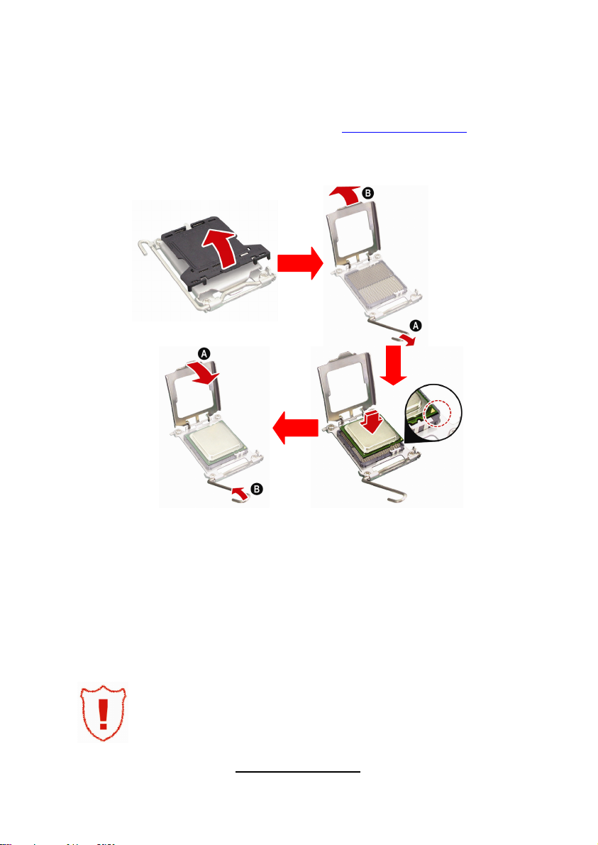
2.4 - Installing the Processor
Your brand new S4992 supports the latest 64-bit processor technology from
AMD®. Only AMD® Opteron™ Rev. F 8000 series processors are certified and
supported with this motherboard.
Check our website for latest processor support. http://www.TYAN.com
®
is not liable for damage as a result of operating an unsupported
TYAN
configuration.
The diagram is provided as a visual guide to help you install the socket
processor and may not be an exact representation of the processor you have.
Step 1: Take off the CPU protection cap.
Step 2: Pull the CPU lever up to unlock the CPU socket (A). Then open the
socket in the direction as shown (B).
Step 3: Place the CPU on the CPU socket, ensuring that pin 1 is located in the
right direction.
Step 4: Close the CPU socket cover (A) and press the CPU socket lever down
to secure the CPU (B).
Take care when installing the processor as it has very fragile
connector pins below the processor and can bend and break
if inserted improperly.
18
http://www.TYAN.com
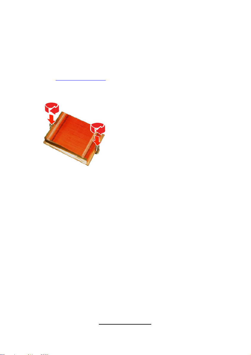
2.5 - Heat sink Installation
After installing the processor, you should proceed to install the heat sink. The
CPU heat sink will ensure that the processor do not overheat and continue to
operate at maximum performance for as long as you own them. The overheated
processor is dangerous to the motherboard.
For the safest method of installation and information on choosing the
appropriate heat sink, use heat sinks validated by AMD. Please refer to AMD’s
website at http://www.amd.com.
The following diagram illustrates how to install heat sink onto the CPU of S4992.
Place the heat sink on top of the CPU
and secure it to the motherboard using
two screws clockwise.
19
http://www.TYAN.com
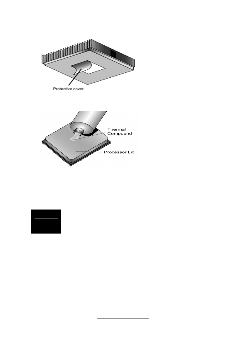
2.6 - Thermal Interface Material
Always check with the manufacturer of the heat sink &
NOTE
processor to ensure the Thermal Interface material is
compatible with the processor & meets the manufacturer’s
warranty requirements
There are two types of
thermal interface materials
designed for use with the
AMD® Opteron™
processors.
The most common material
comes as a small pad
attached to the heat sink at
the time of purchase. There
should be a protective cover
over the material. Take care
not to touch this material.
Simply remove the protective
cover and place the heat
sink on the processor.
The second type of interface
material is usually packaged
separately. It is commonly
referred to as ‘thermal
compound’. Simply apply a
thin layer on to the CPU lid
(applying too much will
actually reduce the cooling).
20
http://www.TYAN.com

2.7 - Finishing Installing the Heat sink
After you have finished installing the heat sink onto the processor and
socket, attach the end wire of the fan (which should already be attached to
the heat sink) to the motherboard. The following diagram illustrates how to
connect fans onto the motherboard.
Once you have finished installing all the fans you can connect your drives
(hard drives, CD-ROM drives, etc.) to your motherboard.
21
http://www.TYAN.com
2.8 - Tips on Installing Motherboard in Chassis
Before installing your motherboard, make sure your chassis has the
necessary motherboard support studs installed. These studs are usually
metal and are gold in color. Usually, the chassis manufacturer will pre-install
the support studs. If you are unsure of stud placement, simply lay the
motherboard inside the chassis and align the screw holes of the
motherboard to the studs inside the case. If there are any studs missing,
you will know right away since the motherboard will not be able to be
securely installed.
22
http://www.TYAN.com
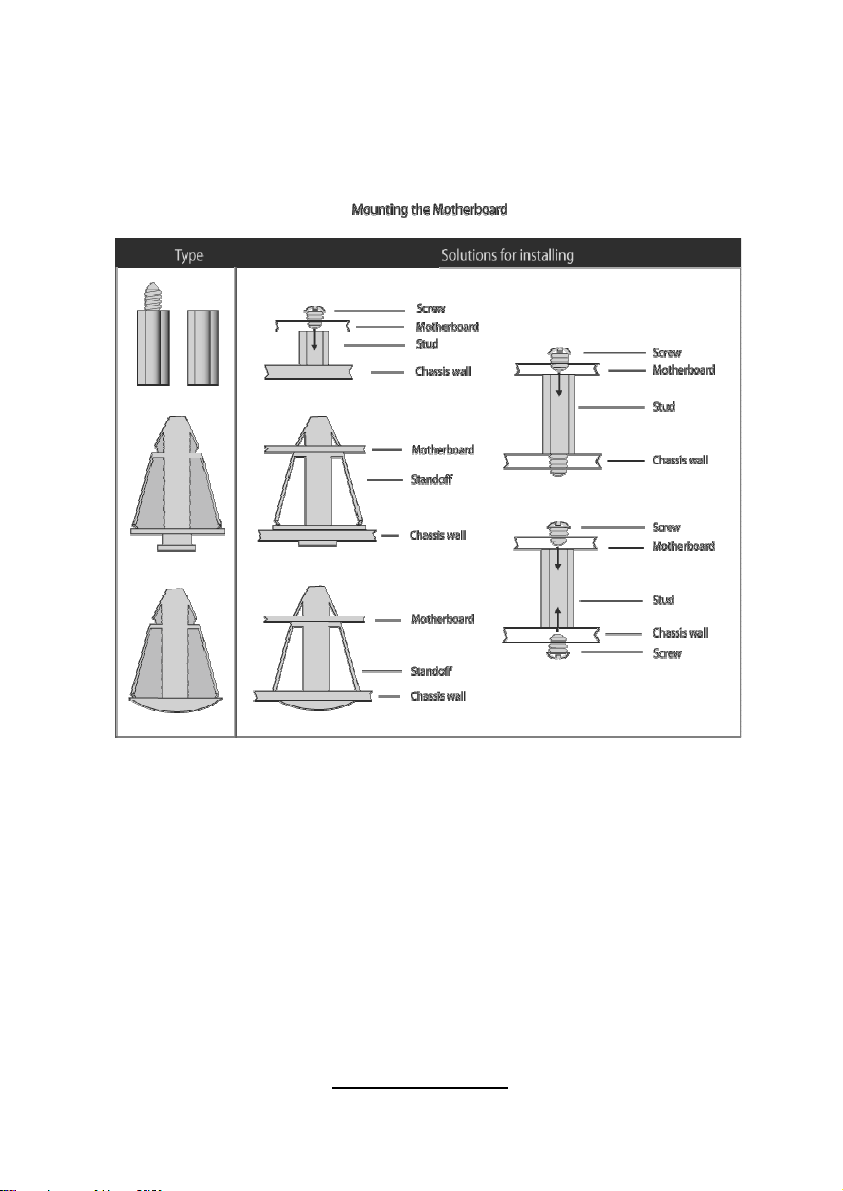
Some chassis’ include plastic studs instead of metal. Although the plastic
studs are usable, TYAN® recommends using metal studs with screws that
will fasten the motherboard more securely in place.
Below is a chart detailing what the most common motherboard studs look
like and how they should be installed
.
23
http://www.TYAN.com
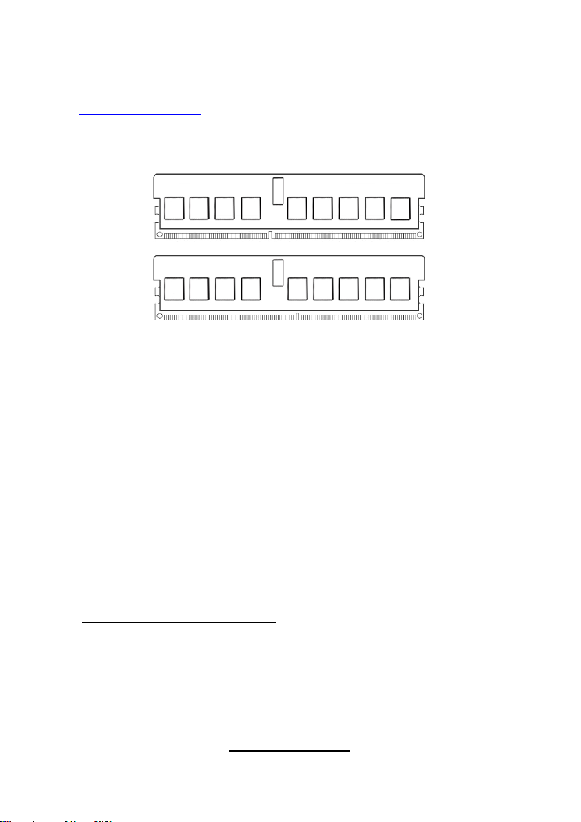
2.9 - Installing the Memory
Before installing memory, ensure that the memory you have is compatible
with the motherboard and processor. Check the TYAN® Web site at:
http://www.TYAN.com
your motherboard.
The following diagram shows common types of DDR2 memory modules.
for details of the type of memory recommended for
• AMD Opteron™ processors support 64bit (non-interleaved) or 128bit
(interleaved) memory configuration.
• ECC Registered DDRII-400/533/667/800 memory modules are
supported. But over 4 DIMM per CPU will cause the memory speed to
clock down to a slower speed at 800MHz, so you cannot have 800MHz
when full load test.
• All installed memory will automatically be detected and no jumpers or
settings need changing.
• S4992 supports up to 256GB of memory.
NOTE:
1). Refer to the memory population option table for detailed memory
configuration instruction.
2). For the DIMM number please refer to the motherboard placement in “2.3 Board Parts, Jumpers and Connectors” for memory installation.
Memory Population Option Table
To correctly install the memory in pairs (DIMMA# + DIMMB#), refer to the
table for supported population options. Start installing Memory modules
from DIMM7 and DIMM8.
24
http://www.TYAN.com
 Loading...