

Page 1

PLASMA
CUTTING TORCH
• Model PCH-62 Hand Torch
• Model PCM-62 Machine Torch
Instruction Manual
January 28, 2004 Manual No. 0-2817
Page 2

Page 3

WARNINGS
Read and understand this entire Manual and your employer’s safety practices before installing, operating, or servicing the equipment.
While the information contained in this Manual represents the Manufacturer's best judgement, the
Manufacturer assumes no liability for its use.
Plasma Cutting T o rc h
Model PCH-62 & PCM-62
Instruction Manual Number 0-2817
Published by
Thermal Dynamics Corporation
82 Benning Street
West Lebanon, New Hampshire, USA 03784
(603) 298-5711
www.thermal-dynamics.com
Copyright 2000 by
Thermal Dynamics Corporation
All rights reserved
Reproduction of this work, in whole or in part, without written permission of the publisher is prohibited.
The publisher does not assume and hereby disclaims any liability to any party for any
loss or damage caused by errors or omissions in this Manual, whether such errors r esult
from negligence, accident, or any other cause.
Printed in the United States of America
Publication Date: January 28, 2004
Record the following information for W arranty purposes:
Where Purchased: _______________________________________
Purchase Date: _______________________________________
Power Supply Serial #: _______________________________________
Torch Serial #: _______________________________________
Page 4

TABLE OF CONTENTS
SECTION 1:
GENERAL INFORMATION ............................................................................................... 1-1
1.01 Notes, Cautions and W arnings ..................................................................... 1-1
1.02 Important Safety Precautions ....................................................................... 1-1
1.03 Publications.................................................................................................. 1-2
1.07 Declaration of Conformity ............................................................................. 1-4
SECTION 2:
INTRODUCTION .............................................................................................................. 2-1
2.01 Scope of Manual .......................................................................................... 2-1
2.02 General Description ..................................................................................... 2-1
2.03 Specifications & Design Features................................................................. 2-1
2.04 Options And Accessories ............................................................................. 2-2
2.05 Introduction to Plasma.................................................................................. 2-2
SECTION 3:
INSTALLATION ................................................................................................................. 3-1
3.01 Introduction .................................................................................................. 3-1
3.02 Site Location ................................................................................................ 3-1
3.03 Unpacking .................................................................................................... 3-1
3.04 Setting Up Hand Torch ................................................................................. 3-1
3.05 Setting Up Machine Torch ............................................................................ 3-1
3.06 Connecting Torch ......................................................................................... 3-2
3.07 Gas Connection ........................................................................................... 3-4
SECTION 4:
OPERATION ..................................................................................................................... 4-1
4.01 Introduction .................................................................................................. 4-1
4.02 Functional Overview..................................................................................... 4-1
4.03 Getting Started............................................................................................. 4-1
4.04 Torch Parts Selection ................................................................................... 4-2
4.05 Cut Quality ................................................................................................... 4-2
4.06 General Cutting Information ......................................................................... 4-3
4.07 Hand Torch Operation .................................................................................. 4-4
4.08 Machine Torch Oper ation ............................................................................. 4-5
4.09 Recommended Cutting Speeds.................................................................... 4-6
4.10 Gouging ....................................................................................................... 4-7
Page 5

TABLE OF CONTENTS (continued)
SECTION 5:
SERVICE .......................................................................................................................... 5-1
5.01 Introduction .................................................................................................. 5-1
5.02 General Torch Maintenance ......................................................................... 5-1
5.03 Common Operating Faults ........................................................................... 5-2
5.04 Inspection and Replacement Consumable Torch Parts ................................ 5-2
5.05 Troubleshooting Guide ................................................................................. 5-3
5.06 T orch & Leads Troubleshooting .................................................................... 5-4
5.07 Servicing Hand Torch (PCH) Components ................................................... 5-6
5.08 Servicing Machine Torch (PCM) Components.............................................. 5-9
SECTION 6:
PARTS LISTS.................................................................................................................... 6-1
6.01 Introduction .................................................................................................. 6-1
6.02 Ordering Information .................................................................................... 6-1
6.03 Replacement Hand Torch Parts (Ergonomic Handle) ................................... 6-2
6.04 Replacement Machine Torch Parts ............................................................... 6-4
6.05 Replacement Torch Lead Parts ................................................................... 6-6
6.06 Complete Torch & Leads Assembly Replacement ........................................ 6-7
6.07 Options and Accessories .............................................................................6-8
6.08 T orch Spare P a rts Kits ................................................................................. 6-9
APPENDIX 1: TYPICAL SYSTEM SEQ UENCE OF OPERATION BLOCK DIAGRAMS ...........A-1
For CutMaster 50 Applications .............................................................................A-1
For P akMaster 50XL Plus Applications.................................................................A-2
APPENDIX 2: TORCH CONTROL CABLE WIRING DIAGRAM
FOR MECHANIZED SYSTEMS........................................................................................ A-3
APPENDIX 3: GENERAL APPLICATION NOTES..................................................................... A-4
APPENDIX 4: CUTMASTER 50 APPLICATION........................................................................A-6
APPENDIX 5: PAKMASTER 50XL PLUS APPLICATION.......................................................... A-8
APPENDIX 6: CE PAKMASTER 50XL PLUS APPLICATION..................................................A-10
APPENDIX 7: HAND TORCH CONNECTION .........................................................................A-12
Page 6

Page 7
SECTION 1:
GENERAL INFORMATION
1.01 Notes, Cautions and Warnings
Throughout this manual, notes, cautions, and warnings
are used to highlight important information. These highlights are categorized as follows:
NOTE
An operation, procedure, or background information which requires additional emphasis or is helpful in efficient operation of the system.
CAUTION
A procedure which, if not properly followed, may
cause damage to the equipment.
WARNING
A procedure which, if not properly followed, may
cause injury to the operator or others in the operating area.
1.02 Important Safety Precautions
WARNINGS
OPERATION AND MAINTENANCE OF
PLASMA ARC EQUIPMENT CAN BE DANGEROUS AND HAZARDOUS TO YOUR
HEALTH.
Plasma arc cutting produces intense electric and
magnetic emissions that may interfere with the
proper function of cardiac pacemakers, hearing aids,
or other electronic health equipment. Persons who
work near plasma arc cutting applications should
consult their medical health professional and the
manufacturer of the health equipment to determine
whether a hazard exists.
To prevent possible injury, read, understand and
follow all warnings, safety precautions and instructions before using the equipment. Call 1-603-2985711 or your local distributor if you have any questions.
GASES AND FUMES
Gases and fumes produced during the plasma cutting
process can be dangerous and hazardous to your health.
• Keep all fumes and gases from the breathing area.
Keep your head out of the welding fume plume.
• Use an air-supplied respirator if ventilation is not
adequate to remove all fumes and gases.
• The kinds of fumes and gases from the plasma arc
depend on the kind of metal being used, coatings
on the metal, and the different processes. Y ou must
be very careful when cutting or welding any metals which may contain one or more of the following:
Antimony Chromium Mercury
Arsenic Cobalt Nickel
Barium Copper Selenium
Beryllium Lead Silver
Cadmium Manganese Vanadium
• Always read the Material Safety Data Sheets
(MSDS) that should be supplied with the material
you are using. These MSDSs will give you the information regarding the kind and amount of fumes
and gases that may be dangerous to your health.
• For information on how to test for fumes and gases
in your workplace, refer to item 1 in Subsection 1.03,
Publications in this manual.
• Use special equipment, such as water or down draft
cutting tables, to capture fumes and gases.
• Do not use the plasma torch in an area where combustible or explosive gases or materials are located.
• Phosgene, a toxic gas, is generated from the vapors
of chlorinated solvents and cleansers. Remove all
sources of these vapors.
• This product, when used for welding or cutting, produces fumes or gases which contain chemicals
known to the State of California to cause birth defects and, in some cases, cancer . (California Health
& Safety Code Sec. 25249.5 et seq.)
ELECTRIC SHOCK
Electric Shock can injure or kill. The plasma arc process
uses and produces high voltage electrical energy. This
electric energy can cause severe or fatal shock to the operator or others in the workplace.
• Never touch any parts that are electrically “live” or
“hot.”
May 14, 2002 1-1 GENERAL INFORMATION
Page 8
• Wear dry gloves and clothing. Insulate yourself
from the work piece or other parts of the welding
circuit.
• Repair or replace all worn or damaged parts.
• Extra care must be taken when the workplace is
moist or damp.
• Install and maintain equipment according to NEC
code, refer to item 9 in Subsection 1.03, Publications.
• Disconnect power source before performing any service or repairs.
• Read and follow all the instructions in the Operating Manual.
FIRE AND EXPLOSION
Fire and explosion can be caused by hot slag, sparks, or
the plasma arc.
• Be sure there is no combustible or flammable material in the workplace. Any material that cannot be
removed must be protected.
• Ventilate all flammable or explosive vapors from
the workplace.
• Do not cut or weld on containers that may have held
combustibles.
• Provide a fire watch when working in an ar ea where
fire hazards may exist.
• Hydrogen gas may be formed and trapped under
aluminum workpieces when they are cut underwater or while using a water table. DO NOT cut alu-
minum alloys underwater or on a water table unless the hydrogen gas can be eliminated or
dissipated. Trapped hydrogen gas that is ignited
will cause an explosion.
NOISE
Noise can cause permanent hearing loss. Plasma arc processes can cause noise levels to exceed safe limits. You
must protect your ears from loud noise to prevent permanent loss of hearing.
• To protect your hearing from loud noise, wear pr otective ear plugs and/or ear muffs. Protect others
in the workplace.
• Noise levels should be measured to be sure the decibels (sound) do not exceed safe levels.
• For information on how to test for noise, see item 1
in Subsection 1.03, Publications, in this manual.
PLASMA ARC RAYS
Plasma Arc Rays can injure your eyes and burn your skin.
The plasma arc process produces very bright ultra violet
and infra red light. These arc rays will damage your eyes
and burn your skin if you are not properly protected.
• To protect your eyes, always wear a welding helmet or shield. Also always wear safety glasses with
side shields, goggles or other protective eye wear.
• Wear welding gloves and suitable clothing to protect your skin from the arc rays and sparks.
• Keep helmet and safety glasses in good condition.
Replace lenses when cracked, chipped or dirty.
• Protect others in the work area from the arc rays.
Use protective booths, screens or shields.
• Use the shade of lens as suggested in the following
per ANSI/ASC Z49.1:
Minimum Protective Suggested
Arc Current Shade No. Shade No.
Less Than 300* 8 9
300 - 400* 9 12
400 - 800* 10 14
* These values apply where the actual arc is clearly
seen. Experience has shown that lighter filters may
be used when the arc is hidden by the workpiece.
1.03 Publications
Refer to the following standards or their latest revisions
for more information:
1. OSHA, SAFETY AND HEALTH STANDARDS, 29CFR
1910, obtainable from the Superintendent of Documents,
U.S. Government Printing Office, Washington, D.C.
20402
2. ANSI Standard Z49.1, SAFETY IN WELDING AND
CUTTING, obtainable from the American Welding Society, 550 N.W. LeJeune Rd, Miami, FL 33126
3. NIOSH, SAFETY AND HEALTH IN ARC WELDING
AND GAS WELDING AND CUTTING, obtainable from
the Superintendent of Documents, U.S. Government
Printing Office, Washington, D.C. 20402
4. ANSI Standard Z87.1, SAFE PRACTICES FOR OCCUP A TION AND EDUCATIONAL EYE AND FACE PROTECTION, obtainable from American National Standards Institute, 1430 Broadway, New York, NY 10018
5. ANSI Standard Z41.1, STANDARD FOR MEN’S
SAFETY -TOE FOOTWEAR, obtainable from the American National Standards Institute, 1430 Broadway, New
York, NY 10018
GENERAL INFORMATION 1-2 May 14, 2002
Page 9

6. ANSI Standard Z49.2, FIRE PREVENTION IN THE USE
OF CUTTING AND WELDING PROCESSES, obtainable from American National Standards Institute, 1430
Broadway, New York, NY 10018
7. AWS Standar d A6.0, WELDING AND CUTTING CONTAINERS WHICH HAVE HELD COMBUSTIBLES, obtainable from American Welding Society, 550 N.W.
LeJeune Rd, Miami, FL 33126
8. NFPA Standard 51, OXYGEN-FUEL GAS SYSTEMS
FOR WELDING, CUTTING AND ALLIED PROCESSES, obtainable from the National Fire Protection
Association, Batterymarch Park, Quincy, MA 02269
9. NFPA Standard 70, NATIONAL ELECTRICAL CODE,
obtainable from the National Fire Protection Association, Batterymarch Park, Quincy, MA 02269
10. NFPA Standard 51B, CUTTING AND WELDING PROCESSES, obtainable from the National Fire Protection
Association, Batterymarch Park, Quincy, MA 02269
11. CGA Pamphlet P-1, SAFE HANDLING OF COMPRESSED GASES IN CYLINDERS, obtainable from the
Compressed Gas Association, 1235 Jefferson Davis
Highway, Suite 501, Arlington, VA 22202
12. CSA Standard W1 17.2, CODE FOR SAFETY IN WELDING AND CUTTING, obtainable from the Canadian
Standards Association, Standards Sales, 178 Rexdale
Boulevard, Rexdale, Ontario, Canada M9W 1R3
13. NWSA booklet, WELDING SAFETY BIBLIOGRAPHY
obtainable from the National Welding Supply Association, 1900 Arch Street, Philadelphia, PA 19103
14. American W elding Society Standard A WSF4.1, RECOMMENDED SAFE PRACTICES FOR THE PREPARATION FOR WELDING AND CUTTING OF CONT AINERS AND PIPING THAT HAVE HELD HAZARDOUS
SUBSTANCES, obtainable fr om the American Welding
Society, 550 N.W. LeJeune Rd, Miami, FL 33126
15. ANSI Standard Z88.2, PRACTICE FOR RESPIRATOR Y
PROTECTION, obtainable from American National
Standards Institute, 1430 Broadway, New York, NY
10018
May 14, 2002 1-3 GENERAL INFORMATION
Page 10

1.07 Declaration of Conformity
Manufacturer: Thermal Dynamics Corporation
Address: 82 Benning Street
W est Lebanon, New Hampshire 03784
USA
The equipment described in this manual conforms to all applicable aspects and regulations of the ‘Low Voltage Directive’
(European Council Directive 73/23/EEC as amended by Council Directive 93/68/EEC) and to the National legislation for
the enforcement of this Directive.
Serial numbers are unique with each individual piece of equipment and details description, parts used to manufacture a unit
and date of manufacture.
National Standard and Technical Specifications
The product is designed and manufactured to a number of standards and technical requir ements. Among them are:
* CSA (Canadian Standards Association) standard C22.2 number 60 for Arc welding equipment.
* UL (Underwriters Laboratory) rating 94VO flammability testing for all printed-circuit boar ds used.
* ISO/IEC 60974-1 (BS 638-PT10) (EN 60 974-1) (EN50192) (EN50078) applicable to plasma cutting equipment and associ-
ated accessories.
* Extensive product design verification is conducted at the manufacturing facility as part of the routine design and manufac-
turing process. This is to ensure the product is safe, when used according to instructions in this manual and related
industry standards, and performs as specified. Rigorous testing is incorporated into the manufacturing process to ensure
the manufactured product meets or exceeds all design specifications.
Thermal Dynamics has been manufacturing products for more than 30 years, and will continue to achieve excellence in our
area of manufacture.
Manufacturers responsible repr esentative: Steve W ard
Operations Director
Thermadyne Europe
Europa Building
Chorley N Industrial Park
Chorley , Lancashire,
England PR6 7BX
GENERAL INFORMATION 1-4 May 14, 2002
Page 11

1.08 Statement of Warranty
LIMITED WARRANTY: Thermal Dynamics® Corporation (hereinafter “Thermal”) warrants that its products will be free of defects in
workmanship or material. Should any failure to conform to this warranty appear within the time period applicable to the Thermal
products as stated below , Thermal shall, upon notification thereof and substantiation that the product has been stor ed, installed, operated,
and maintained in accordance with Thermal’s specifications, instructions, recommendations and recognized standard industry practice,
and not subject to misuse, repair , neglect, alteration, or accident, corr ect such defects by suitable r epair or replacement, at Thermal’s sole
option, of any components or parts of the product determined by Thermal to be defective.
THIS WARRANTY IS EXCLUSIVE AND IS IN LIEU OF ANY WARRANTY OF MERCHANTABILITY OR FITNESS FOR A
PARTICULAR PURPOSE.
LIMITATION OF LIABILITY: Thermal shall not under any circumstances be liable for special or consequential damages, such as, but
not limited to, damage or loss of purchased or replacement goods, or claims of customers of distributor (hereinafter “Purchaser”) for
service interruption. The remedies of the Purchaser set forth herein are exclusive and the liability of Thermal with respect to any
contract, or anything done in connection therewith such as the performance or breach thereof, or from the manufacture, sale, delivery,
resale, or use of any goods covered by or furnished by Thermal whether arising out of contract, negligence, strict tort, or under any
warranty, or otherwise, shall not, except as expressly provided herein, exceed the price of the goods upon which such liability is based.
THIS WARRANTY BECOMES INVALID IF REPLACEMENT PARTS OR ACCESSORIES ARE USED WHICH MAY IMPAIR THE
SAFETY OR PERFORMANCE OF ANY THERMAL PRODUCT.
THIS WARRANTY IS INVALID IF THE PRODUCT IS SOLD BY NON-AUTHORIZED PERSONS.
The limited warranty periods for Thermal products shall be as follows (with the exception of XL Plus Series, CutMaster Series , Cougar
and DRAG-GUN): A maximum of three (3) years from date of sale to an authorized distributor and a maximum of two (2) years from
date of sale by such distributor to the Purchaser, and with the further limitations on such two (2) year period (see chart below).
The limited warranty period for XL Plus Series and CutMaster Series shall be as follows: A maximum of four (4) years from date
of sale to an authorized distributor and a maximum of three (3) years from date of sale by such distributor to the Purchaser, and
with the further limitations on such three (3) year period (see chart below).
The limited warranty period for Cougar and DRAG-GUN shall be as follows: A maximum of two (2) years from date of sale to an
authorized distributor and a maximum of one (1) year from date of sale by such distributor to the Purchaser, and with the further
limitations on such two (2) year period (see chart below).
Parts
XL Plus & Parts Parts
PAK Units, Power Supplies CutMaster Series Cougar/Drag-Gun All Others Labor
Main Power Magnetics 3 Years 1 Year 2 Years 1 Year
Original Main Power Rectifier 3 Years 1 Year 2 Years 1 Year
Control PC Board 3 Years 1 Year 2 Years 1 Year
All Other Circuits And Components Including, 1 Year 1 Year 1 Year 1 Year
But Not Limited To, Starting Circuit,
Contactors, Relays, Solenoids, Pumps,
Power Switching Semi-Conductors
Consoles, Control Equipment, Heat 1 Year 1 Year 1 Year
Exchanges, And Accessory Equipment
Torch And Leads
Maximizer 300 To rch 1 Year 1 Year
SureLok Torches 1 Year 1 Year 1 Year
All Other To rches 180 Days 180 Days 180 Days 180 Days
Repair/Replacement Parts 90 Days 90 Days 90 Days None
Warranty repairs or replacement claims under this limited warranty must be submitted by an authorized Thermal Dynamics® repair
facility within thirty (30) days of the repair. No transportation costs of any kind will be paid under this warranty. Transportation
charges to send products to an authorized warranty repair facility shall be the responsibility of the customer. All returned goods shall
be at the customer’s risk and expense. This warranty supersedes all previous Thermal warranties.
Effective August 6, 2001
May 14, 2002 1-5 GENERAL INFORMATION
Page 12

GENERAL INFORMATION 1-6 May 14, 2002
Page 13

SECTION 2:
INTRODUCTION
2.01 Scope of Manual
This manual contains descriptions, operating instructions
and maintenance procedures for the PCH/M-62 Torch.
Service of this equipment is restricted to properly trained
personnel; unqualified personnel are strictly cautioned
against attempting repairs or adjustments not covered in
this manual, at the risk of voiding the Warranty.
Read this manual thoroughly. A complete understanding of the characteristics and capabilities of this equipment will assure the dependable operation for which it
was designed.
2.02 General Description
NOTE
Refer to Section 2.05, Introduction to Plasma, for
a more detailed description on plasma theory.
The T orch provides cutting capacity of up to 1/2 inch (12.7
mm) at 60 amperes drawn at the power supply.
In the torch, a single torch lead provides compr essed air
from a single source to be used as both the plasma and
secondary gas. The air flow is divided inside the torch
head. Single - gas operation allows for a smaller sized
torch and inexpensive operation.
2.03 Specifications & Design Features
Refer to Appendix Pages for additional specifications as
related to the Power Supply used.
A. Torch Configurations and Dimensions
1. Hand Torch
Available with torch head at 70° and 90° to the
torch handle. The hand torches include an ergonomic torch handle and torch trigger assembly.
2. Machine Torch
The standard machine torch has a fiberglass posi-
tioning tube with rack & pinch block assembly.
A vailable options include a kit with metal mount-
ing tube with rack & pinion assembly or a kit with
the pinion assembly only.
10.5 in
(267 mm)
3.0 in
(76.2 mm)
1.1in
(28 mm)
Plasma torches are similar in design to the common automotive spark plug. They consist of negative and positive sections which are separated by a center insulator.
Inside the torch, the pilot arc is initiated in the gap between the negatively charged electrode and the positively
charged tip. Once the pilot arc has ionized the plasma
gas, the superheated column of gas flows through the
small orifice in the torch tip, which is focused on the metal
to be cut.
10.0 in
(254 mm)
3.4 in
(86.4 mm)
1.1in
(28 mm)
14.1 in
(358 mm)
1.4 in
(35.6 mm)
0.6 in
(15.2 mm)
13.5 in (343 mm) Max
3.7 in (94 mm) Min
0.8 in
(20.3 mm)
5.1 in
(129.5 mm)
1.1 in
(28 mm)
A-02813
Figure 2-1 Torch Configurations and Dimensions
Manual 0-2817 2-1 INTRODUCTION
Page 14

B. Torch Leads Lengths
2.04 Options And Accessories
Hand Torch: 20 ft (6.1 m) or 50 ft (15.2 m)
Machine Torch: 25 ft (7.6 m) or 50 ft (15.2 m)
C. Torch Par ts
Gas Distributor , Electrode, Tip, Shield Cup
D. Par ts - In - Place (PIP)
Torch Head has built - in contacts
12vdc circuit rating.
E. Type of Cooling
Combination of ambient air and gas stream through
torch
F. Torch Ratings
Torch Ratings
Ambient
Temperature
Duty Cy cle
Maxi mu m C u r r e n t
Voltage (V
Arc Stri king Voltage
peak
)
100% @ 60 Amps @ 375 scfh
104° F
(40° C)
60 Amps
500V
12 kV
G. Plasma Power Supply Used With
• CutMaster 50
• PakMaster 50XL Plus
• CE CutMaster 50
• CE PakMaster 50XL Plus
H. Direct Contact Hazard
For exposed tip the recommended standoff is 1/8" 3/8" or 3.2 - 9.5 mm.
These items can be used to customize a standard system
for a particular application or to further enhance performance (refer to Section 6 for ordering information).
• Spare Parts Kits - V arious kits containing replace-
ment front - end torch parts for various applications.
• Circle Cutting Guide Kit - Easy add - on attach-
ments to allow for straight line, circle cutting, and
beveling with a hand torch. The guide fits both
the 70° and 90° hand torches.
• Standoff Cutting Guide - Simple push - on attach-
ment to allow for torch dragging without risk of
touching tip to workpiece.
• 1-3/8" Metal Mounting Tube with Rack & Pinion
Assembly
• Pinion Assembly - For machine torches.
• Computer Control (CNC) Cable 25 ft (7.6 m) or
50 ft (15.2 m)
• Hand Pendant Control Assembly - Used for ma-
chine applications. Hand Pendant Control has 20
ft. (6.1 m) cable which provides ON / OFF signals to the Power Supply.
• Extension Cable for Hand Pendant Control - 25 ft
(7.6 m) cable which can be added to the Hand
Pendant Control cable to provide a total control
cable length of 50 ft (15.2 m).
2.05 Introduction to Plasma
A. Plasma Gas Flow
Plasma is a gas which has been heated to an extremely
high temperature and ionized so that it becomes electrically conductive. The plasma arc cutting and gouging process use this plasma to transfer an electrical
arc to the workpiece. The metal to be cut or removed
is melted by the heat of the arc and then blown away.
While the goal of plasma arc cutting is separation of
the material, plasma arc gouging is used to remove
metals to a controlled depth and width.
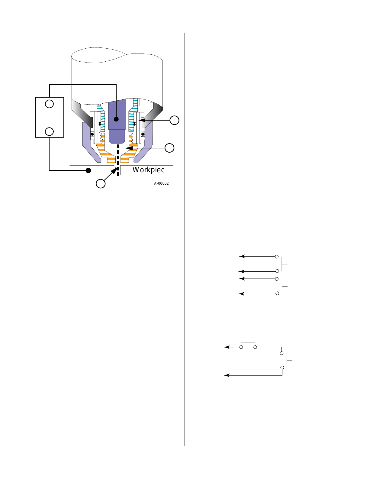
In a Plasma Cutting Torch a cool gas enters Zone B
(refer to Figure 2-2), where a pilot arc between the
electrode and the torch tip heats and ionizes the gas.
The main cutting arc then transfers to the workpiece
through the column of plasma gas in Zone C.
INTRODUCTION 2-2 Manual 0-2817
Page 15
_
Power
Supply
+
D. Capacitive Discharge (CD)
Because direct current (DC) alone is not sufficient to
strike and maintain the pilot arc, capacitive discharge
is also used. The high voltage jumps between the tip
and electrode with the DC following.
E. Main Cutting Arc
DC power is also used for the main cutting arc. The
negative output is connected to the torch electrode
through the torch lead. The positive output is con-
A
nected to the workpiece via the work cable and to
the torch through a pilot wir e.
F. Interlocks
Workpiece
C
Figure 2-2 Typical Torch Head Detail
By forcing the plasma gas and electric arc through a
small orifice, the torch delivers a high concentration
of heat to a small area. The stiff, constricted plasma
arc is shown in Zone C. Direct current (DC) straight
polarity is used for plasma cutting, as shown in the
illustration.
Zone A is used as a secondary gas that cools the torch.
This gas assists the high velocity plasma gas in blowing the molten metal out of the cut allowing for a
fast, slag - free cut.
B. Gas Distribution
The single gas used is internally split into plasma and
secondary gases.
The plasma gas flows into the torch through the negative lead, through the gas distributor , around the electrode, and out through the tip orifice.
The secondary gas flows down around the outside
of the torch gas distributor, and out between the tip
and shield cup around the plasma arc.
C. Pilot Arc
When the torch is started a pilot arc is established
between the electrode and cutting tip. This pilot arc
creates a path for the main arc to transfer to the work.
A-00002
B
One pressure switch acts as an interlock for the gas
supply. If supply pressure falls below minimum requirements the pressure switch will open, shutting
off the DC power, and the GAS Indicator will go off.
When adequate gas supply pressure is available the
pressure switch will close, allowing power to be resumed for cutting.
G. Parts - In - Place (PIP)
The torch head has built - in contacts called Parts - In
- Place (PIP). These two contacts are made through
the ring inside the shield cup when the shield cup is
installed. The torch will fail to operate if these contacts are not made.
To Control
Cable Wiring
A-03540
Torch Switch
PIP Pins
Torch Trigger
Shield Cup
Figure 2-5 Parts - In - Place (PIP) Diagram (Hand
Torch)
Torch Switch
To Control
Cable Wiring
PIP Pin
Shield Cup
PIP Pin
A-00458
Figure 2-3 Parts - In - Place (PIP) Diagram (Machine
Torch)
Manual 0-2817 2-3 INTRODUCTION
Page 16

INTRODUCTION 2-4 Manual 0-2817
Page 17
SECTION 3:
INSTALLATION
3.01 Introduction
This section describes installation of the Torch. These
instructions apply to the T orch and Leads Assemblies only .
Installation procedures for the Power Supply , Options and
Accessories are provided in Manuals specifically provided for those products.
The complete installation consists of:
• Site Selection
• Unpacking
• Setting Up T or c h
• Connecting T orch
• Gas Connection
3.02 Site Location
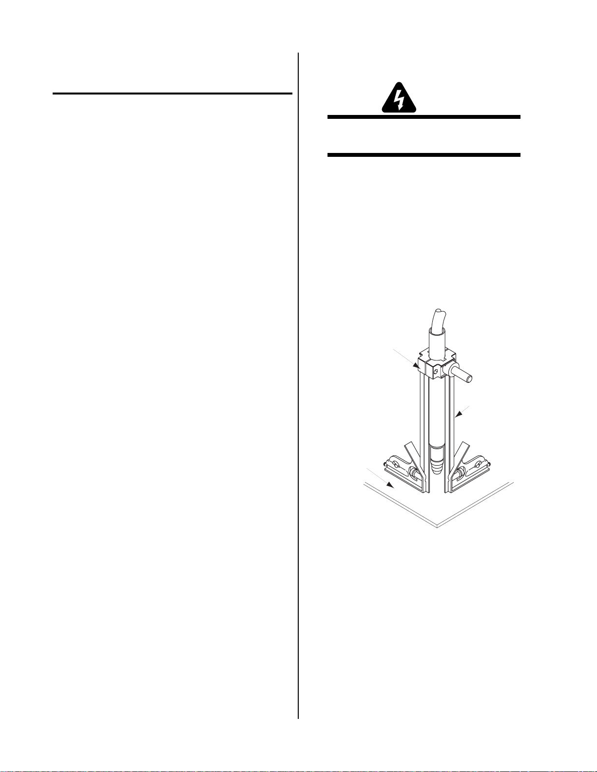
3.05 Setting Up Machine Torch
WARNING
Disconnect primary power at the source before disassembling the torch or torch leads.
The machine torch is factory assembled to the Power Supply. The standard machine torch includes a fiberglass
positioning tube with rack and pinch block assembly. A
metal mounting tube with rack & pinion assembly or the
pinion assembly only are available as options.
1. Mount the torch assembly on the cutting table.
2. T o obtain a clean vertical cut, use a squar e to align
the torch perpendicular to the surface of the workpiece.
Select a clean, dry location with good ventilation and adequate working space around all components.
Review the safety precautions in the front of this manual
to be sure that the location meets all safety requirements.
3.03 Unpacking
Each component of the system is packaged and protected
with a carton and packing material to prevent damage
during shipping.
1. Unpack each item and remove all packing material.
2. Locate the packing list(s) and use the list to identify
and account for each item.
3. Inspect each item for possible shipping damage. If
damage is evident, contact your distributor and / or
shipping company before proceeding with system
installation.
3.04 Setting Up Hand Torch
The hand torch is factory assembled to the Power Supply
and requires no special set up. The proper torch parts
(shield cup, tip, gas distributor, and electrode) must be
installed for the type of operation. Refer to Section 4.04,
Torch Parts Selection for more information.
Pinch Block
Assembly
Square
Workpiece
A-02591
Figure 3-1 Machine Torch Set - Up
3. The proper torch parts (shield cup, tip, gas distributor, and electrode) must be installed for the
type of operation. Refer to Section 4.04, Torch
Parts Selection for more information.
Manual 0-2817 3-1 INST ALLATION
Page 18
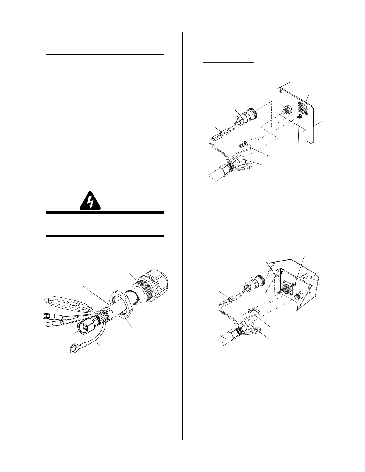
3.06 Connecting T orc h
NOTE
4. Connect the torch Negative / Plasma Lead to the
bulkhead connection inside the Power Supply.
Equipment ordered as a system will have the T or ch
factory connected to the Power Supply.
The instructions for connecting the Torch Leads to the
Power Supply are different depending on the type of
leads. This sub - section covers connecting the T o r ch for
the following applications:
A. Hand Systems
B. Machine Systems (Unshielded Leads)
C. Remote Pendant Control (Optional)
The T orch Leads must be pr operly installed to the Power
Supply for proper operation. If the torch leads were not
factory - installed, make all torch connections to the T or ch
Bulkhead Panel for the desired application.
A. Hand Systems
WARNING
Disconnect primary power at the source before disassembling the torch or torch leads.
Note: Actual Bulkhead
configuration may
differ from that shown.
Adapter
Adapter
Control Circuit
Connectors
Negative/Plasma
Lead Connection
Torch Lead
Assembly
or ATC Adapter
Pilot Lead
Negative/Plasma
Lead
Connector
Pilot Lead Stud
A-03542
Figure 3-3 Torch Lead Connections For CutMaster
50 Power Supply
1. Remove the nut from the Through - hole protector .
Torch Leads
Assembly
Negative /
Plasma Lead
Thru-Hole Protector
Thru-Hole Protector Nut
Pilot Lead
Art # A-03852
Figure 3-2 Through - hole protectorNut Removal
2. Pass the torch lead ends and the Through - hole
protector into the hole in the unit.
3. Secure the Through - hole protector with the nut
removed earlier.
Note: Actual Bulkhead
configuration may
differ from that shown.
Adapter
Control Circuit
Connectors
Torch Leads
Assembly or
ATC Adapter
A-03527
Adapter
Connector
Plug
Negative/Plasma
Pilot Lead Stud
Negative/Plasma Lead
Connection
Pilot Lead
Lead
Figure 3-4 Torch Lead Connections For PakMaster
50XL Plus Power Supply
5. Connect the T orch Leads Cables to the mating connectors on the Adapter supplied on the Power
Supply.
6. Remove the top nut and washer from the Pilot
Stud.
INST ALLATION 3-2 Manual 0-2817
Page 19

7. Place the lug on the Pilot Control Wire onto the
Adapter
(Supplied With
Power Supply)
Pilot Lead
Torch Lead
Assembly
Negative/Plasma
Lead
Adapter Connector
Pilot Lead
Stud
Negative/Plasma
Lead Connection
A-02828
Control (PIP) Circuit
Connectors
Shield Connectors
(Not Used)
Remote
Cable
Connector
stud and secure with the nut and washer removed
in the above Step.
8. Tighten the Through - hole protector onto the
Torch Leads.
9. Check the torch for proper parts assembly.
CAUTION
Note: Actual Bulkhead
configuration may
differ from that shown.
Shield Connectors
(Not Used)
Negative/Plasma
Lead Connection
Adapter
(Supplied With
Power Supply)
Adapter
Connector
The torch parts must correspond with the type of
operation. Refer to Section 4.04, Torch Parts Selection.
B. Machine Systems (Unshielded Leads)
1. Remove the Through - hole protector Nut from
the Through - hole protector.
Torch Leads
Assembly
Thru - Hole Protector
Art # A-03847
Thru - Hole
ProtectorNut
Control (PIP) Circuit
Connectors
Pilot Lead
Stud
Remote
Cable
Connector
Negative/Plasma
Torch Lead
Assembly
Pilot Lead
Lead
A-02768
Figure 3-6 Torch Lead Connections For CutMaster
50 Power Supply
Figure 3-5 Through - hole protector Nut Removal
2. The Adapter supplied with the Power Supply
must be installed per the following:
a. Inside the Power Supply Bulkhead area, route
the connector on the free end of the Adapter
through the Through - hole protector Nut.
b. Continue routing the connector out the hole
in the front of the Power Supply.
c. Pass the end of the torch lead and the Through
- hole protector into the hole in the unit while
routing the single black wire into the notch of
the Through - hole protector.
d. Tighten the Through - hole protector Nut to
secure the Through - hole protector to the
Power Supply.
3. Connect the torch Negative / Plasma Lead to the
Figure 3-7 Torch Lead Connections For PakMaster
50XL Plus Power Supply
bulkhead connection inside the Power Supply.
Manual 0-2817 3-3 INST ALLATION
Page 20

4. Connect the Control (PIP) Circuit Connectors to
the mating connectors on the Adapter supplied
on the Power Supply (see Warning).
WARNING
The Adapter supplied with the Power Supply has
two additional Shield Connectors that are used for
Shielded Systems only. These two connectors are
not used and need to be taped out of the way to
prevent contacting the Negative / Plasma or Pilot
Leads.
5. Remove the top nut and washer from the Pilot
Stud.
6. Place the lug on the Pilot Control Wire onto the
stud and secure with the nut and washer removed
in the above Step.
Remote Pendant/CNC
Cable Connector
Control
12
OK-To-Move
14
13
3
4
PIP
Circuit
Torch Control
Cable Connector
2
3
4
12
14
13
A-01366
Figure 3-8 Remote Pendant Connector Diagram
7. Tighten the Through - hole protector onto the
Torch Leads.
8. Check the torch for proper parts assembly.
CAUTION
The torch parts must correspond with the type of
operation. Refer to Section 4.04, Torch Parts Selection.
D. Remote Pendant Control (Optional)
In machine type operations the Power Supply has an
Adapter that has a cable connector supplied at each
end of the Adapter. One end is connected at the factory to the mating connector on the Power Supply
Bulkhead area. The other end allows connection of a
Remote Pendant. The remote pendant lead connector allows connection to a remote pendant or CNC
cable while using PIP connections in the Torch Assembly.
Connect the remote pendant control cable to the connector provided on the Adapter fr om the Power Supply.
NOTE
Refer to Appendix 2, Torch Control Cable Wiring
Diagram For Mechanized Systems, for detailed
schematic of the Adapter.
3.07 Gas Connection
A. Connection
Connect the gas, compressed air only, to the Power
Supply as described in the Manual supplied with the
Power Supply.
CAUTION
Air supply must be free of oil, moisture, and other
contaminants. Excessive oil and moisture may
cause double - arcing, rapid tip wear , or even complete torch failure. Contaminants may cause poor
cutting performance and rapid electrode wear.
B. Checking Air Quality
T o test the quality of air, place a welding filter lens in
front of the torch and turn on the gas. Any oil or
moisture in the air will be visible on the lens. Do not
initiate an arc!
C. Filtering
An in - line pneumatic dryer / evaporator type air
filter, capable of filtering to at least 5 microns, is required when using air from a compressor. This type
filter will insure that moisture, oil, dirt, chips, rust
particles, and other contaminants from the supply
hose do not enter the torch. For highly automated
applications, a refrigerated drier may be used
INST ALLATION 3-4 Manual 0-2817
Page 21

SECTION 4:
OPERATION
4.01 Introduction
This section provides a description of the Torch Assembly followed by operating procedures.
4.02 Functional Overview
The T orch is designed to operate with various Power Supplies to provide a plasma cutting system which can cut
most metals from gauge thickness up to 1/2 inch (12.7
mm). Using gouging torch parts the torch can be used
for plasma arc gouging up to 1/8 inch (3.2 mm) wide
and 1/8 inch (3.2 mm) deep in a single pass on carbon
steel.
NOTE
Refer to Appendix Pages for additional information as related to the Power Supply used.
4.03 Getting Started
This procedure should be followed at the beginning of
each shift:
NOTE
Refer to Appendix Pages for additional information as related to the Power Supply used.
E. Power On
Place the ON / OFF Switch on the Power Supply to
the ON position. If the RUN / SET or RUN / SET /
LATCH switch is in SET position, gas will flow. If
the switch is in RUN position there will be no gas
flow.
F. RUN / SET or RUN / SET / LATCH Switch
If the RUN / SET or RUN / SET / LATCH switch is
in SET position, gas will flow . If the switch is in RUN
position there will be no gas flow.
G. Current Output Level
At the Power Supply, set the desired current output
level between 20 - 40 amps for cutting or gouging.
H. Pressure Setting
Place the RUN / SET or RUN / SET / LA TCH switch
to the SET position. Adjust the gas pressure control
on the Power Supply for the proper gas pressur e (see
Note).
NOTE
WARNING
Disconnect primary power at the source before assembling or disassembling power supply, torch
parts, or torch and leads assemblies.
A. Torch Parts
Check that torch is properly connected and assembled. Install proper torch parts for the desired
application (refer to Section 4.04, Torch Parts Selection).
B. Input Power
Check the power source for proper input voltage.
Close main disconnect or plug the unit in to supply
primary power to the system.
C. Work Cable
Check for a solid work cable connection to the workpiece.
D. Gas Supply
Select desired single gas supply. Make sure gas
sources meet requirements (see Note). Check connections and turn gas supply on.
Refer to Appendix Pages for additional information as related to the Power Supply used.
I. Ready for Operation
Return the RUN / SET or RUN / SET / LATCH
switch to RUN position.
NOTES
For general cutting, use the RUN position which
provides normal torch operation where the torch
switch must be held throughout the main arc transfer.
For specific applications, use the LATCH position
where the torch switch can be r eleased after the main
arc transfer . The torch r emains activated until the
main arc breaks from the workpiece.
Refer to Appendix I for a typical detailed block diagram of Sequence of Operations.
The system is now ready for operation.
Start the pilot arc. On Hand T or ches press the T or ch T rig-
ger . On Machine T or ches press the switch on the Remote
Pendant or supply a Start Signal from the CNC control.
There is a 2 second pre-flow before the arc starts.
Manual 0-2817 4-1 OPERATION
Page 22

4.04 Torch Parts Selection
4.05 Cut Quality
The type of power supply and the type of operation to be
performed determine the torch parts to be used:
Type of operation:
Drag cutting, standoff cutting or gouging
Torch parts:
Shield Cup, Cutting Tip, Electrode and Gas Distributor
NOTE
Refer to Appendix Pages for additional information as related to the Power Supply used.
To change the torch parts for a different operation use
the following procedure:
NOTE
The tip and gas distributor are held in place by the
shield cup. Position the torch with the Shield cup
facing upward to prevent these parts from falling
out when the cup is removed.
1. Unscrew and remove the shield cup from the torch
head.
Torch Head Assembly
(70˚ Hand Torch Shown)
Electrode
Gas
Distributor
NOTES
Cut quality depends heavily on set-up and parameters such as torch standoff, alignment with the
workpiece, cutting speed, gas pressures, and operator ability.
Refer to Appendix Pages for additional information as related to the Power Supply used.
Cut quality requirements differ depending on application. For instance, nitride build-up and bevel angle may
be major factors when the surface will be welded after
cutting. Dross-free cutting is important when finish cut
quality is desired to avoid a secondary cleaning operation. The following cut quality characteristics are illustrated in the following figure.
Kerf Width
Cut Surface
Bevel Angle
Top
Spatter
Top Edge
Rounding
Dross
Build-Up
Cut Surface
Drag Lines
A-00007
Figure 4-2 Cut Quality Characteristics
Tip
A-02890
Shield Cup
Figure 4-1 Torch Parts
2. Tilt the torch head to remove the tip and gas distributor .
3. Remove the SureLok Electrode by pulling it straight
out of the Torch Head.
4. Install the desired SureLok Electrode by pushing it
straight into the torch head until it clicks.
5. Install the desired gas distributor and tip for the op-
eration into the torch head.
6. Hand tighten the shield cup until it is seated on the
torch head. If resistance is felt when installing the
cup, check the threads before proceeding.
A. Cut Surface
The desired or specified condition (smooth or rough)
of the face of the cut.
B. Nitride Build-Up
Nitride deposits can be left on the surface of the cut
when nitrogen is present in the plasma gas stream.
These build-ups may create difficulties if the material is to be welded after the cutting process.
C. Bevel Angle
The angle between the surface of the cut edge and a
plane perpendicular to the surface of the plate. A perfectly perpendicular cut would result in a 0° bevel
angle.
D. Top-Edge Rounding
Rounding on the top edge of a cut due to wearing
from the initial contact of the plasma arc on the workpiece.
OPERA TION 4-2 Manual 0-2817
Page 23

E. Bottom Dross Build-up
C. Edge Starting
Molten material which is not blown out of the cut
area and re-solidifies on the plate. Excessive dross
may require secondary clean-up operations after cutting.
F . Kerf Width
The width of the cut (or the width of material removed during the cut).
G. Top Spatter (Dross)
Top spatter or dross on the top of the cut caused by
slow travel speed, excess cutting height, or cutting
tip whose orifice has become elongated.
4.06 General Cutting Information
WARNINGS
Disconnect primary power at the source before disassembling the power supply, torch, or tor ch leads.
Frequently review the Important Safety Precautions in Section 1. Be sure the operator is equipped
with proper gloves, clothing, eye and ear protection. Make sure no part of the operator’s body
comes into contact with the workpiece while the
torch is activated.
CAUTION
Sparks from the cutting process can cause damage
to coated, painted, and other surfaces such as glass,
plastic and metal.
NOTE
Handle torch leads with care and protect them fr om
damage.
A. Piloting
Piloting is harder on parts life than actual cutting because the pilot arc is directed from the electrode to
the tip rather than to a workpiece. Whenever possible, avoid excessive pilot arc time to improve parts
life.
B. Torch Standoff
Improper standoff (the distance between the torch
tip and workpiece) can adversely affect tip life as well
as shield cup life. Standoff may also significantly
affect the bevel angle. Reducing standoff will generally result in a more square cut.
For edge starts, hold the torch perpendicular to the
workpiece with the front of the tip near (not touching) the edge of the workpiece at the point where the
cut is to start. When starting at the edge of the plate,
do not pause at the edge and force the arc to "reach"
for the edge of the metal. Establish the cutting arc as
quickly as possible.
D. Direction of Cut
Inside the torch, the plasma gas stream swirls as it
leaves the torch to maintain a smooth column of gas.
This swirl effect results in one side of a cut being mor e
square than the other . Viewed along the direction of
travel, the right side of the cut is more square than
the left.
Left Side
Cut Angle
Right Side
Cut Angle
Figure 4-3 Side Characteristics of Cut
To make a square-edged cut along an inside diameter of a circle, the torch should move counterclockwise around the circle. T o keep the squar e edge along
an outside diameter cut, the torch should travel in a
clockwise direction.
E. Dross
When dross is present on carbon steel, it is commonly
referred to as either “high speed dross", "slow speed
dross", or "top dross”. Dross present on top of the
plate is normally caused by too great a torch-to-plate
distance. "T op dross" is normally very easy to r emove
and can often be wiped off with a welding glove.
"Slow speed dross" is normally present on the bottom edge of the plate. It can vary from a light to heavy
bead, but does not adhere tightly to the cut edge, and
can be easily scraped off. "High speed dross" usually forms a narrow bead along the bottom of the cut
edge and is very difficult to remove. When cutting a
troublesome steel, it is sometimes useful to reduce
the cutting speed to produce "slow speed dross". Any
resultant cleanup can be accomplished by scraping,
not grinding.
A-00512
Manual 0-2817 4-3 OPERATION
Page 24

4.07 Hand T orch Operation
A. Standoff Cutting With Hand Torch
NOTE
For best performance and parts life, always use the
correct parts for the type of operation.
1. The torch can be comfortably held in one hand or
steadied with two hands. Position the hand to
press the Trigger on the torch handle. With the
hand torch, the hand may be positioned close to
the torch head for maximum control or near the
back end for maximum heat protection. Choose
the holding technique that feels most comfortable
and allows good control and movement.
NOTE
The tip should never come in contact with the workpiece except during drag cutting operations.
2. Depending on the cutting operation, do one of the
following:
a. For edge starts, hold the torch perpendicular
to the workpiece with the front of the tip on
the edge of the workpiece at the point where
the cut is to start.
b. For standoff cutting, hold the torch 1/8 - 3/8
in (3-9 mm) from the workpiece as shown below.
4. Once on, the main arc remains on as long as the
Torch Trigger is held down, unless the torch is
withdrawn from the work or torch motion is too
slow. If the cutting arc is interrupted, the pilot
arc comes back on automatically.
NOTE
Most cutting is performed with the power supply
in the RUN position. For specific applications, the
LATCH position may be pr eferred where the Torch
Trigger can be released after the main arc transfer .
The torch remains activated until the main arc
breaks from the workpiece.
5. To shut off the torch simply r elease the T orch Trigger . When the trigger is released a gas post-flow
will occur. If the Torch Trigger is pushed during
the post-flow , the cutting arc will r estart immediately when the torch is brought within range of
the workpiece.
B. Standoff Cutting Guide With Straight Edge
The Standoff Cutting Guide (option with some systems) can be used with a non-conductive straight
edge to make straight cuts by hand.
WARNING
The straight edge must be non-conductive.
Torch
Shield Cup
A-00024
Standoff
Distance 1/8" - 3/8"
Figure 4-4 Standoff Distance
3. With the torch in starting position, press and hold
the T orch Trigger. After an initial two second preflow, the pilot arc will come on and remain on
until the cutting arc starts.
Torch
Shield Cup
Standoff
Cutting Guide
Non-Conductive
Straight Edge
Cutting Guide
A-02792
Figure 4-5 Using Standoff Cutting Guide With
Straight Edge
The guide functions best when cutting 3/16 inch (4.7
mm) or greater solid metal with relatively smooth
surfaces. Use drag cutting for thinner metal.
OPERA TION 4-4 Manual 0-2817
Page 25

C. Drag Cutting With a Hand Torch
NOTE
Drag cutting works best on metal 3/16" (4.7 mm)
thick or less.
NOTE
For best parts performance and life, always use the
correct parts for the type of operation.
1. Install the drag cutting tip and set the output current to 35 amps or less.
2. The torch can be comfortably held in one hand or
steadied with two hands. Position the hand to
press the Trigger on the torch handle. With the
hand torch, the hand may be positioned close to
the torch head for maximum control or near the
back end for maximum heat protection. Choose
the holding technique that feels most comfortable
and allows good control and movement.
3. Keep the torch in contact with the workpiece during the cutting cycle.
4. Press the Torch Trigger, and after an initial two
second pre-flow, the pilot arc will come on and
remain on until the cutting arc starts.
5. Once on, the main arc remains on as long as the
Torch Trigger is held down, unless the torch is
withdrawn from the work or torch motion is too
slow. If the cutting arc is interrupted, the pilot
arc comes back on automatically.
The tip should never come in contact with the workpiece except during drag cutting operations.
2. Angle the torch slightly to direct blowback particles away from the torch tip (and operator) rather
than directly back into it until the pierce is complete.
3. In a portion of the unwanted metal start the pierce
off the cutting line and then continue the cut onto
the line. Hold the torch perpendicular to the workpiece after the pierce is complete.
4. Clean spatter and scale from the shield cup and
the tip as soon as possible. Spraying the shield
cup in anti-spatter compound will minimize the
amount of scale which adheres to it.
4.08 Machine T orch Operation
A. Cutting With Machine T orch
The machine torch can be activated by remote control pendant or by a remote interface device such as
CNC.
1. Use a square to check that the torch is perpendicular to the workpiece to obtain a clean, vertical cut.
NOTE
Most cutting is performed with the power supply
in the RUN position. For specific applications,
the LATCH position may be preferred where the
Torch Trigger can be released after the main arc
transfer . In the LATCH position, the tor ch remains
activated until the main arc breaks from the workpiece.
6. T o shut off the tor ch simply release the T orch Trigger . When the T rigger is r eleased a gas post-flow
will occur. If the Torch Trigger is pushed during
the post-flow , the cutting arc will r estart immediately when the torch is brought within range of
the workpiece.
D. Piercing With Hand T or ch
1. The torch can be comfortably held in one hand or
steadied with two hands. Position the hand to
press the Trigger on the torch handle. With the
hand torch, the hand may be positioned close to
the torch head for maximum control or near the
back end for maximum heat protection. Choose
the technique that feels most comfortable and allows good control and movement.
Pinch Block
Assembly
Square
Workpiece
A-02591
Figure 4-6 Checking Alignment
2. To start a cut at the plate edge, position the center
of the torch along the edge of the plate (refer to
Figure 4-7).
Manual 0-2817 4-5 OPERATION
Page 26

B. Travel Speed
Proper travel speed is indicated by the trail of the arc
which is seen below the plate ( Figure 4-7). The arc
can be one of the following:
1. Straight Arc
A straight arc is perpendicular to the workpiece
surface. This arc is generally recommended for
the best cut using air plasma on stainless or aluminum.
2. Leading Arc
The leading arc is directed in the same direction
as torch travel. A five degr ee leading arc is gener ally recommended for air plasma on mild steel.
3. Trailing Arc
The trailing arc is directed in the opposite direction as torch travel. Generally recommended for
Nitrogen Plasma.
Travel speed also affects the bevel angle of a cut.
When cutting in a circle or around a corner, slowing
down the travel speed will result in a squarer cut.
The power source output should be reduced also.
Refer to the approriate Power Supply Operating
Manual for any Corner Slowdown (CSD) adjustments
that may be required.
C. Piercing With Machine T orch
To pierce with a machine torch, the arc should be
started with the torch positioned as high as possible
above the plate while allowing the arc to transfer and
pierce. This standoff helps avoid having molten metal
blow back onto the front end of the torch.
When operating with a cutting machine, a pierce or
dwell time is required. Torch travel should not be
enabled until the arc penetrates the bottom of the
plate. As motion begins, torch standoff should be
reduced to the recommended 1/8 - 1/4 inch (3-6 mm)
distance for optimum speed and cut quality. Clean
spatter and scale from the shield cup and the tip as
soon as possible. Spraying or dipping the shield cup
in anti-spatter compound will minimize the amount
of scale which adheres to it.
Direction of Torch Travel
Standoff Distance
A-02590
Straight Arc
Trailing Arc
Leading Arc
Figure 4-7 Machine Torch Operation
For optimum smooth surface quality , the travel speed
should be adjusted so that only the leading edge of
the arc column produces the cut. If the travel speed
is too slow, a rough cut will be produced as the arc
moves from side to side in search of metal for transfer.
4.09 Recommended Cutting Speeds
Cutting speed depends on material, thickness, and the
operator’s ability to accurately follow the desired cut line.
The following factors may have an impact on system performance:
• Torch parts wear
• Air quality
• Line voltage fluctuations
• Torch standoff height
• Proper work cable connection
NOTES
This information represents realistic expectations
using recommended practices and well-maintained
systems. Actual speeds may vary up to 50% from
those shown.
Refer to Appendix Pages for cutting speed chart
information as related to the Power Supply used.
OPERA TION 4-6 Manual 0-2817
Page 27

4.10 Gouging
A-00025
35˚
Workpiece
Torch Head
Standoff Height
1/8 - 1/4"
Direction of Travel
WARNINGS
Be sure the operator is equipped with proper gloves,
clothing, eye and ear protection and that all safety
precautions at the front of this manual have been
followed. Make sure no part of the operator’s body
comes in contact with the workpiece when the torch
is activated.
Disconnect primary power to the system before
disassembling the torch, leads, or power supply.
CAUTIONS
35°), less material may be removed, requiring more
passes. In some applications, such as removing welds
or working with light metal, this may be desirable.
Sparks from plasma gouging can cause damage to
coated, painted or other surfaces such as glass, plastic, and metal.
Check torch parts. The torch parts must correspond
with the type of operation. Refer to Section 4.04,
Torch Parts Selection.
A. Gouging Parameters
Gouging performance depends on parameters such
as torch travel speed, current level, lead angle (the
angle between the torch and workpiece), and the distance between the torch tip and workpiece (standoff).
B. Tor ch Tra vel Speed
NOTE
Refer to Appendix Pages for additional information as related to the Power Supply used.
Optimum torch travel speed for gouging is dependent on current setting, and lead angle, and mode of
operation (hand or machine torch).
C. Current Setting
Figure 4-8 Gouging Angle and Standoff Distance
E. Standoff Distance
The tip to work distance affects gouge quality and
depth. Standoff distance of 1/8 - 1/4 inch (3 - 6 mm)
allows for smooth, consistent metal removal. Smaller
standoff distances may result in a severance cut rather
than a gouge. Standoff distances greater than 1/4
inch (6 mm) may result in minimal metal removal or
loss of transferred main arc.
F. Slag Build-up
Slag generated by gouging on materials such as carbon and stainless steels, nickels, and alloyed steels,
can be removed easily in most cases. Slag does not
obstruct the gouging process if it accumulates to the
side of the gouge path. However, slag build-up can
cause inconsistencies and irregular metal removal if
large amounts of material build up in front of the arc.
The build-up is most often a result of improper travel
speed, lead angle, or standoff height.
Current settings depend on torch travel speed, mode
of operation (hand or machine torch), and the amount
of material to be removed.
D. Lead Angle
The angle between the torch and workpiece depends
on the output current setting and torch travel speed.
At 40 amps, the recommended lead angle is 35°. At a
lead angle greater than 45° the molten metal will not
be blown out of the gouge and may be blown back
onto the torch. If the lead angle is too small (less than
Manual 0-2817 4-7 OPERATION
Page 28

OPERA TION 4-8 Manual 0-2817
Page 29

SECTION 5:
SERVICE
5.01 Introduction
This section describes basic maintenance procedures performable by operating personnel. No other adjustments
or repairs are to be attempted by other than properly
trained personnel.
WARNINGS
The inside of the torch should be cleaned with electrical contact cleaner using a cotton swab or soft wet
rag. In severe cases, the torch can be removed from
the leads and cleaned more thoroughly by pouring
electrical contact cleaner into the torch and blowing
it through with compressed air.
Refer to Section 5.07, Servicing Hand Torch (PCH)
Components, or Section 5.08, Servicing Machine
Torch Components (PCM) for disassembling the
Torch and Leads Assembly.
CAUTION
Dry the torch thoroughly before r einstalling.
Disconnect primary power at the source before disassembling the torch or torch leads.
Frequently review the Important Safety Precautions Section 1. Be sure the operator is equipped
with proper gloves, clothing, eye and ear protection. Make sure no part of the operator’s body comes
into contact with the workpiece while the torch is
activated.
CAUTION
Sparks from the cutting process can cause damage
to coated, painted, and other surfaces such as glass,
plastic and metal.
NOTE
Handle torch leads with care and protect them fr om
damage.
5.02 General T orch Maintenance
A. Cleaning Tor ch
Even if precautions are taken to use only clean air
with a torch, eventually the inside of the torch becomes coated with residue. This buildup can affect
the pilot arc initiation and the overall cut quality of
the torch.
WARNINGS
Disconnect primary power to the system before
disassembling the torch or torch leads.
DO NOT touch any internal torch parts while the
AC indicator light of the Power Supply is ON.
B. Checking Center Insulator
The center insulator separates the negative and positive sections of the torch. If the center insulator does
not provide adequate resistance, current which is intended for the pilot arc may be dissipated into the
torch head, resulting in torch failure.
WARNINGS
Disconnect primary power to the system before
disassembling the torch or torch leads.
DO NOT touch any internal torch parts while the
AC indicator light of the Power Supply is ON.
1. Remove the shield cup, tip, gas distributor, and
electrode from the torch. Disconnect the torch
leads from the power supply to isolate the torch
from power supply circuits.
2. Using an ohmmeter (set to 10K or higher), check
for continuity between the positive and negative
torch fittings. Infinite resistance (no continuity)
should be found. If continuity is found, refer to
subsection 5.06, Torch and Leads Troubleshooting.
C. O - Ring Lubrication
The external o - ring on the Torch Head Assembly
(shield cup) requires lubrication on a scheduled basis. This will allow the o - ring to remain pliable and
provide a proper seal. The o - ring will dry out, becoming hard and cracked, if the o - ring lubricant is
not used on a regular basis. This can lead to potential leaks of the secondary gas around the end of the
shield cup.
It is recommended to apply a very light film of o - ring
lubricant (Catalog # 8-4025) to the o - ring on a weekly
basis.
Manual 0-2817 5-1 SERVICE
Page 30

NOTE
DO NOT use other lubricants or grease, they may
not be designed to operate within high temperatures or may contain “unknown elements” that
may react with the atmosphere. This reaction can
leave contaminants inside the torch. Either of these
conditions can lead to inconsistent performance or
poor parts life.
5.03 Common Operating Faults
The following lists the more common cutting faults and
what is the possible cause:
1. Insufficient Penetration
a. Cutting speed too fast
b. Torch tilted too much
c. Metal too thick
d. Worn torch parts
e. Cutting current too low
f. Non - Genuine Thermal Dynamics Parts
2. Main Arc Extinguishes
a. Cutting speed too slow
b. Torch standoff too high from workpiece
5.04 Inspection and Replacement Consumable T or ch Parts
WARNINGS
Disconnect primary power to the system before
disassembling the torch or torch leads. DO NOT
touch any internal torch parts while primary power
is connected.
Remove the consumable torch parts per the following
procedure:
NOTE
The tip and gas distributor are held in place by the
shield cup. Position the torch with the shield cup
facing upward to prevent these parts from falling
out when the cup is removed.
1. Unscrew and remove the shield cup from the torch.
NOTE
Slag built up on the shield cup that cannot be removed may effect the performance of the system.
2. Inspect the cup for damage. Wipe it clean or replace
if damaged.
c. Cutting current too high
d. Work cable disconnected
e. Worn torch parts
f. Non - Genuine Thermal Dynamics Parts
3. Excessive Dross Formation
a. Cutting speed too slow
b. Torch standoff too high from workpiece
c. Worn torch parts
d. Improper cutting current
e. Non - Genuine Thermal Dynamics Parts
4. Short Torch Parts Life
a. Oil or moisture in air source
b. Exceeding system capability (material too thick)
c. Excessive pilot arc time
d. Air flow too low (incorrect pressure)
e. Improperly assembled torch
Torch Head Assembly
(70˚ Hand Torch Shown)
Electrode
A-02890
Gas
Distributor
Tip
Shield Cup
Figure 5-1 Front End Torch Parts Assembly
3. Remove the tip. Check for excessive wear (indicated
by an elongated or oversized orifice). Clean or replace the tip if necessary.
f. Non - Genuine Thermal Dynamics Parts
SERVICE 5-2 Manual 0-2817
Page 31

Good Tip
A-00942
Worn Tip
Figure 5-2 Tip Wear
This guide is set up in the following manner:
X. Symptom (Bold Type)
Any Special Instructions (Text Type)
1. Cause (Italic Type)
a. Check / Remedy (Text Type)
Locate your symptom, check the causes (easiest listed first)
then remedies. Repair as needed being sure to verify that
unit is fully operational after any repairs.
Troubleshooting
4. Remove the gas distributor and check for excessive
wear , plugged gas holes, or discoloration. Replace if
necessary.
5. Remove the SureLok Electrode by pulling it straight
out of the torch head. Refer to the following figure
and check the face of the electrode for excessive wear .
New Electrode
A-02794
Worn Electrode
Figure 5-3 Electrode Wear
6. Reinstall the SurLok electrode into the torch head by
pushing it straight into the torch head until it clicks.
7. Reinstall the gas distributor and tip into the torch head.
8. Hand tighten the shield cup until it is seated on the
torch head. If resistance is felt when installing the
cup, check the threads before proceeding.
5.05 Troubleshooting Guide
This subsection covers troubleshooting that requires
dissasembly and electronic measurements. It is helpful
for solving many of the common problems that can arise
with this torch assembly.
A. Torch will not pilot when torch switch is activated
1. Power Supply RUN / SET or RUN / SET / LATCH
switch in SET position
a. Place switch to RUN position
2. Parts - In - Place (PIP) not satisfied
a. Check canted coil spring inside shield cup
3. Faulty torch switch
a. Check continuity
4. Faulty torch parts
a. Inspect torch parts and replace if necessary. Re-
fer to subsection 5.04, Inspection and Replacement Consumable Torch Parts.
5. Gas pressure too high
a. Set proper operating gas pressure
6. Faulty components in torch and leads assembly.
a. Inspect torch assemblies and replace if neces-
sary . Refer to subsection 5.06, Torch and Leads
Troubleshooting.
7. Faulty components in power supply system components
a. Return for repair or have qualified technician
repair per Service Manual.
B. No cutting output
1. Torch not properly connected to power supply
a. Check that torch leads are properly attached
to power supply.
How to Use This Guide
The following information is a guide to help the Customer
determine the most likely causes for various symptoms.
2. Shield cup not properly installed on torch
a. Check that shield cup is fully seated against
torch head (do not overtighten).
3. Parts - In - Place (PIP) not satisfied
a. Check canted coil spring inside shield cup
Manual 0-2817 5-3 SERVICE
Page 32

4. Faulty components in torch and leads assembly
F. Torch cuts but not adequately
a. Inspect torch assemblies and replace if neces-
sary . Refer to subsection 5.06, Torch and Leads
Troubleshooting.
5. Faulty components in power supply system
a. Return for repair or have qualified technician
repair per Service Manual.
C. Limited cutting output with no control
1. Poor input or output connections to power supply
a. Check all input and output connections.
2. Faulty components in torch and leads assembly
a. Inspect torch assemblies and replace if neces-
sary. Refer to subsection 5.06, Torch & Leads
Troubleshooting.
3. Faulty components in power supply system
a. Return for repair or have qualified technician
repair per Power Supply Service Manual.
D. Erratic or improper cutting output
1. Poor input or output connections to power supply
1. Current set too low at power supply
a. Increase current setting
2. Torch is being moved too fast across workpiece
a. Reduce cutting speed (refer to Appendix Page
for the Power Supply being used).
3. Excessive oil or moisture in torch
a. Hold torch 1/8 inch (3 mm) from clean surface
while purging and observe oil or moisture
buildup (do not activate torch).
5.06 Torch & Leads Troubleshooting
A. General Information
Failures in the Torch & Leads can be isolated to the T orch
Head or T orch Lead components. To properly isolate the
failed part requires the use of an ohmmeter and a Hi Pot T ester.
WARNING
a. Check all input and output connections.
2. Current set too low at power supply
a. Increase current setting.
3. Torch is being moved too fast across workpiece
a. Reduce cutting speed (refer to Appendix Page
for the Power Supply being used).
4. Excessive oil or moisture in torch
a. Hold torch 1/8 inch (3 mm) from clean surface
while purging and observe oil or moisture
buildup (do not activate torch)
E. No gas flow
1. Gas not connected or pressure too low
a. Check source for proper operating gas pressur e
(refer to Appendix Page for the Power Supply
being used).
2. Faulty components in torch and leads assembly
a. Inspect torch assemblies and replace if neces-
sary . Refer to subsection 5.06, Torch and Leads
Troubleshooting.
The use of a Hi - Pot Tester should be performed
only by a qualified electronic technician.
In the T orch Head the center insulator separates the negative and positive charged sections of the torch. If the center insulator does not provide adequate resistance, current which is intended for the pilot arc may be dissipated
into the torch head, resulting in torch failure.
In the Torch Leads the negative and positive leads are
isolated from each other. If there is not adequate resistance between the leads then torch failure may occur.
B. Quick Check Procedure
This quick check will identify major isolation failures in
the T orch Head or T or ch Lead components using an ohmmeter.
The actual assembly and consumables may vary for different torches but the basic procedure is the same for all
torches. Make the quick check on the Torch Head and
Leads per the following procedure:
3. Faulty components in power supply system
a. Return for repair or have qualified technician
repair per Power Supply Service Manual.
SERVICE 5-4 Manual 0-2817
Page 33

WARNINGS
Disconnect primary power to the system before
disassembling the torch or torch leads.
DO NOT touch any internal torch parts while the
AC indicator light of the Power Supply is ON.
C. Checking Proper Isolation Resistance
Procedure
The Torch Head and Torch Leads should be tested further for insulation breakdown if no other fault has been
found. This procedure requir es the use of a Hi - Pot T ester .
WARNING
1. Remove the consumables from the torch.
2. Disconnect the torch leads from the power supply to isolate the torch from power supply circuits.
3. Using an ohmmeter (set to 10K or higher), check
for continuity between the positive and negative
torch fittings.
• If there is continuity between the two torch
fittings proceed to Step 4.
• If no continuity (infinite resistance) is found
between the two torch fittings proceed to paragraph C.
4. Remove the torch head from the leads (refer to
the proper section on servicing the T orch Components).
5. With the torch head disconnected from the leads,
measure the resistance between negative fitting
or cathode body of the torch head and the positive fitting or anode body of the torch head.
No continuity (infinite resistance) should be measured between negative and positive sections of
the torch head.
• If there is continuity, torch head must be re-
placed.
• If no continuity (infinite resistance) is found
proceed to Step 6.
6. Check the torch leads by measuring the resistance
between the positive pilot lead connector and the
negative lead fitting.
• If there is continuity, torch leads must be re-
placed.
• If no continuity (infinite resistance) is found
proceed to paragraph ‘C’ (see NOTE).
NOTE
It is possible that the Torch Head and Torch Leads
will test properly with an ohmmeter. The Torch
Head and Torch Leads should be tested further for
insulation breakdown if no other fault can be found.
This procedure should be performed only by a qualified electronic technician.
1. To test the T or ch Head center insulator for insulation breakdown use the following procedur e:
a. Remove the Torch Head Assembly from the
Torch Leads if not already done.
b. Remove the consumables from the T orch Head
Assembly if not already done.
c. Connect a Hi - Pot Tester capable of produc-
ing 2500VAC between the positive pilot lead
and the negative lead fittings.
d. Increase the output of the Hi - Pot Tester to a
maximum of 2500VAC.
• If the voltage drops to 0VAC or leakage
current of greater than 10mA is detected,
then the Torch Head center insulator is
breaking down and the Torch Head must
be replaced.
• If the Torch Head center insulator passes
the test, then proceed to Step 2.
2. To test the Torch Leads for insulation breakdown
use the following procedure:
a. Connect the Hi - Pot Tester between the posi-
tive pilot lead and the negative lead fittings.
The fitting on the other end of the T orch Leads
must be separated (isolated) from each other.
b. Increase the output of the Hi - Pot Tester to a
maximum of 2500VAC.
• If the voltage drops to 0VAC or leakage
current of greater than 10mA is detected,
then the insulation between the Torch
Leads is breaking down and the Torch
Leads must be replaced.
• If the Tor ch Leads passes the test, then proceed to Step 3.
Manual 0-2817 5-5 SERVICE
Page 34

3. Visually check that the PIP wires, torch switch
wires, pilot lead connection, and negative lead
connections are properly connected and in good
condition (no shorts or arcing).
5.07 Servicing Hand Torch (PCH) Components
To Control
Cable Wiring
A-03540
Torch Switch
PIP Pins
Torch Trigger
Shield Cup
Figure 5-4A HandTorch Switch and PIP Schematic
Torch Switch
To Control
Cable Wiring
PIP Pin
Shield Cup
PIP Pin
A-00458
Figure 5-4B Machine Torch Switch and PIP
Schematic
• If problems are evident, repair or replace as
required.
• If there are no visual problems, then proceed
to Step 4.
WARNINGS
Disconnect primary power to the system before disassembling the torch, leads, or power supply.
NEVER touch any internal torch parts while the
AC indicator light on the Power Supply is ON.
A. Removing the Hand Torch Assembly
The removal of the torch head assembly requires disassembly of the torch handle and leads per the following procedure:
1. Remove the five screws from the torch handle assembly. Pull the halves apart and set aside.
A-02823
Handle Half
4. Check the pilot lead, negative lead and switch control wires for opens from one end of the torch leads
to the other .
• If open, replace leads or open component of
the Torch Leads Assembly.
• If not open, then proceed to Step 5.
5. Check the pilot and switch control wires for shorts
to other components in the Torch Leads.
• If shorted, then replace Torch Leads.
• If not shorted, then proceed to Step 6.
6. Carefully reassemble the components and r echeck
the completed assembly per paragraph ‘B’, Step
3 to confirm that the components have been properly assembled.
This completes the checks for the proper operation of the
Torch Head and Torch Leads.
Handle Screws
(Five Places)
Figure 5-5 Torch Handle Screw Removal
2. Disconnect all wire connectors.
3. Slide the insulation sleeve on the Pilot Lead back
towards the Lead.
4. Remove the screw and star washer securing the
Pilot Lead to the head assembly.
5. Slide the insulation sleeving on the Negative /
Plasma Lead back towards the Lead.
NOTE
Some units may have shrink on tubing instead of
insulation sleeving. If this is the case, remove the
shrink on tubing from the Negative / Plasma Lead,
being careful not to damage the lead under the
shrink on tubing.
SERVICE 5-6 Manual 0-2817
Page 35

Negative / Plasma Lead
Insulation Sleeving
Handle Shell
Spring
Trigger
Pilot Lead
Insulation
Sleeving
Figure 5-6 Hand Torch Assembly
A-03544
Negative/Plasma
Lead Insulation Sleeving
Torch
Switch
A-03545
Handle Shell
Figure 5-7 Insulation Sleeving Position for Negative
/ Plasma Lead
6. Disconnect the Negative / Plasma Lead from the
torch head.
7. Remove the defective torch head.
B. Reassembling the Hand Torch Assembly
WARNING
Disconnect primary power to the system before disassembling the torch, leads, or power supply.
To install the Torch Head Assembly use the following procedure:
IMPORTANT
The insulation sleeves are critical for safety. Be
sure both are properly installed and not damaged
during reassembly.
1. Slide the replacement insulator sleeving over the
Negative / Plasma Lead.
2. Connect the Negative / Plasma Lead to the replacement Torch Head Assembly.
3. Carefully position the insulation sleeving over the
connectors, as shown below.
4. Insert the screw through the Pilot Lead lug and
then install the star washer before securing it to
the Torch Head Assembly.
5. Carefully position the Insulation Sleeving over the
Pilot connection.
Pilot Lead
Insulation Sleeving
A-03546
Figure 5-8 Insulation Sleeving Position for Pilot
Connection
6. Reconnect the wire connectors to the mating connectors in the leads assembly.
Manual 0-2817 5-7 SERVICE
Page 36

7. Place the T orch Head Assembly in the handle shell
halves keeping in mind the following:
• Place the torch head assembly switch leads so
that no connectors or wires extend beyond the
edge of the handle.
C. Removing Hand Torch Control Switch
To remove the Torch Control Switch Assembly requires gaining access to the switch wiring and requires partial disassembly of the torch handle per the
following procedure:
• Allow sufficient slack in the leads to avoid
pulling the leads tightly around the edge of
the handle.
• Position Pilot Lead under the Negative /
Plasma Lead.
• Position the Pilot Lead so that the screw will
not penetrate the Insulation Sleeving when the
handle halves are reassembled.
NOTE
For safety reasons, it is critical that the sleeving
not be used if it is damaged during reassembly.
Replace sleeving if damaged.
8. Place the torch handle halves together and install
the five assembly screws as follows:
a. Insert the two screws at the Torch Head end
of the Handle and torque to 15 in-lbs.
b. Insert the two screws at the T or ch Lead end of
the Handle and torque to 15 in-lbs.
c. Insert the center screw and torque to 15 in-lbs.
1. Remove the five screws from the torch handle assembly. Pull the halves apart and set aside.
A-02823
Handle Half
Handle Screws
(Five Places)
Figure 5-10 Torch Handle Screw Removal
2. Cut the Torch Switch leads between the butt
splices and the torch leads, and as close as possible to the splices.
d. Check the T orch Trigger for proper operation.
It should move freely and not bind. If the trigger binds, loosen the center screw only until
the Trigger moves freely.
A-02824
Handle Half
#3
#1
Install Screws In
Sequence Shown
#2
Figure 5-9 Torch Handle Screw Installation
9. Install the front end torch parts.
Negative / Plasma Lead
Insulation Sleeving
Handle Shell
Spring
Trigger
Pilot Lead
Insulation
Sleeving
Handle Shell
A-03544
Torch
Switch
Figure 5-11 Hand Torch Assembly
3. Remove the defective Torch Switch from the
handle.
SERVICE 5-8 Manual 0-2817
Page 37

D. Replacing Hand Torch Control Switch
1. Strip back the insulation from the Torch Switch
leads approximately 3/16". Install heat-shrink
insulation on the T orch Switch leads. Crimp butt
splices onto the two T or ch Switch leads and onto
the switch leads in the Torch Leads assembly.
Slide the sheat-shrink insulator over the butt
splices. Use a heat gun to shrink the heat-shrink
insulation into position on the butt splices.
5.08 Servicing Machine Torch (PCM) Components
WARNINGS
Disconnect primary power to the system before
disassembling the torch or torch leads.
2. Position Torch Head and Torch Control Switch in
handle, making sure all connectors and leads do
not extend beyond the edge of the handle.
3. Position Pilot Lead under the Negative / Plasma
Lead.
4. Position the Pilot Lead so that the screw will not
penetrate the Insulation Sleeving when the handle
halves are reassembled.
NOTE
For safety reasons, it is critical that the sleeving
not be used if it is damaged during reassembly.
Replace sleeving if damaged.
5. Replace the handle and secure with five screws
as follows:
a. Insert the two screws at the Torch Head end
of the Handle and torque to 15 in-lbs.
b. Insert the two screws at the T or ch Lead end of
the Handle and torque to 15 in-lbs.
c. Insert the center screw and torque to 15 in-lbs.
d. Check the T orch Trigger for proper operation.
It should move freely and not bind. If the trig-
ger binds, loosen the center screw only until
the Trigger moves freely .
A-02824
#2
DO NOT touch any internal torch parts while the
AC indicator light of the Power Supply is ON.
A. Removing Machine Torch Head
1. Unscrew the positioning tube from the Torch
Head.
2. Slide the positioning tube back over the leads to
expose the Negative / Plasma Lead connection,
Pilot Lead connection, and two PIP (parts - in place circuit) connectors.
Pinch Block
Assembly
Positioning
Tube
Machine T orch Head
A-02592
Figure 5-13 Torch Mounting Assembly
4. Disconnect the Negative / Plasma and Pilot Leads
and the PIP connectors to allow removal of the
T o r ch Head Assembly.
Handle Half
#3
#1
Install Screws In
Sequence Shown
Figure 5-12 Torch Handle Screw Installation
Negative/Plasma
Lead Connection
Pilot Lead
Connection
Parts-in-Place
Wires
A-02581
Figure 5-14 Torch Head Removal
Manual 0-2817 5-9 SERVICE
Page 38

C. Reassembling Machine Torch Assembly
1. Connect the two PIP lead connectors, the Negative / Plasma and Pilot leads.
NOTE
T ape the PIP lead connectors to the leads covering.
2. Screw the positioning tube tightly onto the Tor ch
Head Assembly .
SERVICE 5-10 Manual 0-2817
Page 39

SECTION 6:
PARTS LISTS
6.01 Introduction
A. Parts List Breakdown
The parts list provides a breakdown of all replaceable
components. T orch Assemblies are field serviceable, so a
complete breakdown of parts is provided. The parts lists
are arranged as follows:
Section 6.03: Replacement Hand Torch Parts
Section 6.04: Replacement Machine Tor ch Parts
Section 6.05: Replacement Machine Tor ch Lead Parts
Section 6.06: Complete Assembly Replacement
Section 6.07: Options and Accessories
Section 6.08: Tor ch Spar e Parts Kits
NOTE
Parts listed without item numbers are not illustrated, but may be ordered by the catalog numbers
shown.
B. Returns
If a product must be returned for service, contact your
authorized distributor . Materials returned without proper
authorization will not be accepted.
6.02 Ordering Information
Order replacement parts by catalog number and complete
description of the part or assembly, as listed in the description column of the Parts List. Also include the model
and serial number of the torch. Address all inquiries to
your authorized distributor .
Manual 0-2817 6-1 P A RTS LISTS
Page 40

6.03 Replacement Hand Torch Parts (Ergonomic Handle)
Item # Qty Description Catalog #
1 1 Shield Cup Assembly (includes item #2) 9-8400
2 1 O - Ring 8-0532
3 1 Spring, Canted Coil 9-7501
41 Tip (Refer to Appendix Page for the proper application)
5 1 Distributor (Refer to Appendix Page for the proper application)
6 1 Electrode (Refer to Appendix Page for the proper application)
7 1 Assembly, Tor ch Head (includes items #8 & 9)
PCH-62 RPT 70° Torch Head 9-8410
PCH-62 RPT 90° Torch Head 9-8409
8 1 #6-32 x 3/16" Phillips Pan Head Screw See Note
9 1 #6 Internal Star Washer See Note
10 1 Negative/Plasma Lead Insulation Sleeving 9-8067
11 1 Pilot Wire Insulation Sleeving 9-8057
12 3 Pin Housing (used with item #13) 9-81 11
13 3 Pin 9-8101
14 3 Socket Housing (used with item #15) 9-8112
15 3 Socket 9-8102
1 Handle, Split, with Trigger (includes items #16-20) 9-8058
16 1 Trigger, Lexan, Orange 9-8059
17 1 Handle 9-8060
18 1 Spring, 9-8061
19 1 Torch Switch Assembly 9-8063
20 1 Torch Handle Socket Head Cap Screw Kit (5 pcs 6-32 x 1/2" ) 9-8062
21 1 Lead Assembly, including items 17, 19, and 20
20 ft (6.1 m) Length 4-0830
50 ft (15.2 m) Length 4-0831
22 1 Standoff Cutting Guide 9-8415
23 1 Adapter, Torch Control Cable 7-3447
Note: Item can be purchased locally.
P AR TS LISTS 6-2 Manual 0-2817
Page 41

10
11
14 &15
12 &13
17
9
7
2
6
5
8
12 &13
18
16
12 &13
14 &15
19
20
17
21
4
3
1
22
23
NOTE
Illustration may vary slightly from
A-03543
actual torch.
Manual 0-2817 6-3 P A RTS LISTS
Page 42

6.04 Replacement Machine Torch Parts
Item # Qty Description Catalog #
1 1 Shield Cup Assembly (includes item #2), 40A 9-8400
2 1 Spring, Canted Coil 9-7501
3 1 Tip, Cutting, (Refer to Appendix Page for the proper application)
1 Tip, Gouging, (Refer to Appendix Page for the proper application)
4 1 Distributor (Refer to Appendix Page for the proper application)
5 1 Electrode (Refer to Appendix Page for the proper application)
6 1 Assembly, Torch Head, PCM-62 (includes items #7 - 9) 9-8408
7 1 O - Ring (pkg of 5) 8-0532
8 1 #6-32 x 3/16 Phillips Pan Head Screw See Note
9 1 #6 Internal Star Washer See Note
10 1 Unshielded Lead Assembly, Cable Complete
25 ft (7.6 m) Length 4-0832
50 ft (15.2 m) Length 4-0833
11 1 Positioning Tube with Rack, Fiber glass 9-7835
12 2 Body, Mounting, Pinch Block Phenolic (Plastic) 9-4513
13 1 Pin, Mounting, Pinch Block 9-4521
14 1 Torch Holder Sleeve 7-2896
15 3 #10-32 x 5/8" Phillips Pan Head Screw See Note
16 2 #10-32 x 32 x 1 1/4 Lg Phillips Pan Head Screw See Note
17 2 #10-32 Regular Nylon Lock Nut See Note
18 1 Through - hole Protector , Notched (Supplied with Nut) 9-7016
19 3 Pin Housing (used with item #20) 9-5577
20 3 Pin 9-5763
21 3 Socket Housing (used with item #22) 9-5764
22 3 Socket 9-5578
23 1 Adapter, Machine Torch Control Cable 7-3448
24 1 Pinch Block Mounting Kit (includes items 12 - 17) 7-3252
Note: Item can be purchased locally.
P AR TS LISTS 6-4 Manual 0-2817
Page 43

11
24
16
12
15
6
12
7
4
3
2
1
5
9
8
19 & 20
21 & 22
13
17
14
10
23
Art # A-02787
18
21 & 22
19 & 20
Manual 0-2817 6-5 P A RTS LISTS
Page 44

6.05 Replacement Torch Lead Parts
Item # Qty Description Catalog #
1 1 Nylon Sleeving
25 ft (7.6 m) Length 9-5515
50 ft (15.2 m) Length 9-5516
2 1 Through - hole Protector , Notched (Supplied with Nut) 9-7016
3 1 Boot 9-7017
4 1 Lead, Pilot Return, 14A WG
25 ft (7.6 m) Length 8-6460
50 ft (15.2 m) Length 8-6461
5 1 Lead, Negative, #4 Hose - #12 AWG
25 ft (7.6 m) Length 9-9032
50 ft (15.2 m) Length 9-9033
6 1 Assembly, Control Cable (Unshielded Leads)
25 ft (7.6 m) Length 8-6462
50 ft (15.2 m) Length 8-6463
PCM-62 Unshielded Torc h Leads
5
4
1
2
3
A-02802
6
P AR TS LISTS 6-6 Manual 0-2817
Page 45

6.06 Complete Torch & Leads Assembly Replacement
NOTE
The Complete Torch & Leads Assembly Replacement does not include the Torch Control Cable Adapter (refer to
Section 6.03 or 6.04)
Description Catalog #
Hand Torches with Ergonomic Handle:
PCH-62 RPT 70° Hand Torch, 20 ft (6.1 m) Leads 7-6220
PCH-62 RPT 70° Hand Torch, 50 ft (15.2 m) Leads 7-6221
PCH-62 RPT 90° Hand Torch, 20 ft (6.1 m) Leads 7-6222
PCH-62 RPT 90° Hand Torch, 50 ft (15.2 m) Leads 7-6223
Machine Torches with Unshielded Leads (Fiberglass Mounting T ube with Rack & Phenolic Pinch Block Assembly):
PCM-62 RPT Machine Torch, 25 ft (7.6 m) Leads 7-6224
PCM-62 RPT Machine Torch, 50 ft (15.2 m) Leads 7-6225
Manual 0-2817 6-7 P A RTS LISTS
Page 46

6.07 Options and Accessories
Item # Qty Description Catalog #
1 Standoff Cutting Guide 9-8415
1 Cutting Guide Kit 7-8910
1 T rigger Guard Kit 9-8418
1 Hand Pendant Extension - 25 ft 7-7744
1 Computer Control (CNC) Cable
25 Ft (7.6 m) 8-5557
50 Ft (15.2 m) 8-5558
Kevlar Sleeving:
1 25 ft. (7.6 m) 9-7905
1 50 ft. (15.2 m) 9-7906
1 1-3/8" Metal Positioning Tube with Rack & Pinion Assembly Kit 7-7745
1 Pinion Assembly Only 7-2827
1 1 Torch Holder Sleeve 7-2896
2 1 Pinion Gear - Short 8-6074
3 1 Handwheel (Torch Holder) 9-4514
4 1 Low Profile Torch Holder (1 3/8 Dia) without Hardware 9-4515
5 1 Calibrated Torch Holder Bushing 9-4366
6 1 5/32 Dia x 5/8 Lg Slotted Spring Pin See Note
7 1 3/8 - 24 x 3/8 Soc Hd Set Screw, Cup Point See Note
8 2 1/4 - 20 x 5/8 Hex Socket Head Screw See Note
9 1 #10 - 24 x 3/8 Hex Socket Set Screw, Cup Point See Note
10 1 Remote Hand Pendant Control with 20 ft. Cable 7-3460
Note: Item can be purchased locally.
7
8
3
6
9
1
8
4
2
A-02814
5
P AR TS LISTS 6-8 Manual 0-2817
Page 47

6.08 Torch Spare Parts Kits
A. For CutMaster 50 Applications
1. For Non - CE CutMaster 50 Applications
Qty Description Catalog #
Introductory Spare Parts Kit Includes: 5-6208
3 Electrode (SureLok), MaximumLife 9-8407
5 Tip, Cutting, Air , 40 Amp (0.031" Orifice) 9-8411
1 O - Ring 8-0532
1 Canted Coil Spring, 0.985" I.D. 9-7501
1 Adapter Fitting 1/4 NPT to #4 Hose (1/4" or 6mm) 8-4264
1 Lubricant 8-4025
1 Box, Utility 8-3141
1 Standoff Cutting Guide 9-8415
2 Velcro Hook #65, 3/4" wide x 3" long n/a
2 Velcro Loop, #1000, 3/4" wide x 3" long n/a
VIP Spare Parts Kit Includes: 5-6201
25 Electrode (SureLok), MaximumLife 9-8407
50 Tip, Cutting, Air , 40 Amp (0.031" Orifice) 9-8411
1 Gas Distributor , 40A 9-8401
1 Shield Cup, 40A 9-8400
2 Canted Coil Spring, 0.985 9-7501
2. For CE CutMaster 50 Applications
Qty Description Catalog #
Introductory Spare Parts Kit Includes: 5-6208
3 Electrode (SureLok), MaximumLife 9-8407
5 Tip, Cutting, Air , 40 Amp (0.031" Orifice) 9-8411
1 O - Ring 8-0532
1 Canted Coil Spring, 0.985" I.D. 9-7501
1 Adapter Fitting 1/4 NPT to #4 Hose (1/4" or 6mm) 8-4264
1 Lubricant 8-4025
1 Box, Utility 8-3141
1 Standoff Cutting Guide 9-8415
2 Velcro Hook #65, 3/4" wide x 3" long n/a
2 Velcro Loop, #1000, 3/4" wide x 3" long n/a
Manual 0-2817 6-9 P A RTS LISTS
Page 48

B. For PakMaster 50XL Plus Applications
Qty Description Catalog #
1. For Non - CE PakMaster 50XL Plus Applications
Standard Spare Parts Kit Includes: 5-6203
3 Electrode (SureLok), MaximumLife 9-8407
2 Tip, Cutting/Drag, Air, 40 Amp (0.031" Orifice) 9-8411
5 Tip, Cutting (Standoff), Air, 40 Amp (0.031" Orifice) 9-8412
1 Box, Utility 8-3141
1 Adapter Fitting 1/4 NPT to #4 Hose (1/4" or 6mm) 8-4264
1 Standoff Cutting Guide 9-8415
1 O - Ring 8-0532
1 Canted Coil Spring 9-7501
2 Velcro Hook #65, 3/4" wide x 3" long n/a
2 Velcro Loop, #1000, 3/4" wide x 3" long n/a
VIP Spare Parts Kit Includes: 5-6205
25 Electrode (SureLok), MaximumLife 9-8407
20 Tip, Cutting/Drag, Air, 40 Amp (0.031" Orifice) 9-8411
30 Tip, Cutting (Standoff), Air, 40 Amp (0.031" Orifice) 9-8412
1 Gas Distributor 9-8401
1 Shield Cup 9-8400
2 Canted Coil Spring 9-7501
1 Standoff Cutting Guide 9-8415
2. For CE PakMaster 50XL Plus Applications
Qty Description Catalog #
Standard Spare Parts Kit Includes: 5-6209
3 Electrode (SureLok), General Purpose 9-8402
2 Tip, Cutting/Drag, Air, 40 Amp (0.031" Orifice) 9-8411
5 Tip, Cutting (Standoff), Air, 40 Amp (0.031" Orifice) 9-8412
1 Box, Utility 8-3141
1 Adapter Fitting 1/4"NPT to #4 Hose (1/4" or 6mm) 8-4264
1 Standoff Cutting Guide 9-8415
1 O - Ring 8-0532
1 Canted Coil Spring 9-7501
2 Velcro Hook #65, 3/4" wide x 3" long n/a
2 Velcro Loop, #1000, 3/4" wide x 3" long n/a
P AR TS LISTS 6-10 Manual 0-2817
Page 49

APPENDIX 1: TYPICAL SYSTEM SEQUENCE OF
OPERATION BLOCK DIAGRAMS
For CutMaster 50 Applications
ACTION
Close external
disconnect switch.
RESULT
Power to system.
ACTION
Protect eyes and
activate torch.
RESULT
Gas flows (2 seconds).
After gas pre-flow:
DC indicator on.
Pilot relay closes.
Pilot arc established
ACTION
ON/OFF switch
to ON.
RESULT
AC indicator blinks for 8
seconds then steady on.
Fans on.
Power circuit ready.
gas flows to set pressure.
PILOT ARC
ACTION
RUN/SET switch
to SET.
RESULT
Gas solenoid open,
GAS indicator on.
ACTION
RUN/SET
switch to RUN.
RESULT
Gas flow stops.
GAS indicator off.
ACTION
Torch moved away
from work (while
still activated).
RESULT
Main arc stops.
Pilot arc automatically
restarts.
ACTION
Torch moved within
transfer distance of workpiece.
ACTION
Torch deactivated (by torch switch
release or by remote device).
RESULT
(Power supply enable signal removed)
post-flow, pilot arc will immediately restart.
(1/4 in/6.4mm) of workpiece, main arc
Gas solenoid closes, gas flow stops.
Main arc stops.
Gas flows (10 seconds)
NOTE - If torch is activated during
If torch is within transfer distance
will transfer.
After post-flow:
GAS indicator off.
ACTION
ON/OFF switch
to OFF
RESULT
All indicators off.
Power supply fans off.
RESULT
Main arc transfer.
Pilot arc off.
ACTION
Open external
disconnect.
RESULT
No power to system.
A-02778
Manual 0-2817 A-1 APPENDIX
Page 50

For PakMaster 50XL Plus Applications
LATCH
ACTION
Close external
disconnect switch.
RESULT
Power to system.
ACTION
Protect eyes and
activate torch
RESULT
Gas flows (2 seconds).
After gas pre-flow:
DC indicator on.
Pilot relay closes.
Pilot arc established
ACTION
ON/OFF switch
to ON.
RESULT
AC indicator blinks for 8
seconds then steady on.
Fans on.
Power circuit ready.
RUN/SET/LATCH switch
gas flows to set pressure.
PILOT ARC
ACTION
to SET.
RESULT
Gas solenoid open,
GAS indicator on.
ACTION
RUN/SET/LATCH
switch to RUN.
RESULT
Gas flow stops.
GAS indicator off.
ACTION
Torch moved away
from work (while
still activated).
RESULT
Main arc stops.
Pilot arc automatically
restarts.
ACTION
Torch deactivated (by torch switch
release or by remote device).
RESULT
(Power supply enable signal removed.)
post-flow, pilot arc will immediately restart.
If torch is within transfer distance (3/8 in) of
Gas solenoid closes, gas flow stops.
Main arc stops.
Gas flows (15 seconds)
NOTE - If torch is activated during
workpiece, main arc will transfer.
After post-flow:
GAS indicator off.
ACTION
ON/OFF switch
to OFF
RESULT
All indicators off.
Power supply fans off.
ACTION
Torch moved within
transfer distance of workpiece.
RESULT
Main arc transfer.
Pilot arc off.
ACTION
Open external
disconnect.
RESULT
No power to system.
ACTION
Torch Switch
can be released.
RESULT
Transfer will continue
until torch is removed
from workpiece.
A-02461
APPENDIX A-2 Man ual 0-2817
Page 51

T o Torch
Control Device
APPENDIX 2: TORCH CONTROL CABLE WIRING
DIAGRAM FOR MECHANIZED SYSTEMS
Torch Control
Cable
Torch Control
Connectors
Control Shield
Connector
Control Connector
Plug with Connectors
To Power Supply
Control Connector
Shield
Return
Power Supply
Control
OK-To-Move
Relay
A-02821
2
1
3
4
12
14
Torch Lead
Assembly
Mate & Lock
Connectors
Lead Shield
Connector
Torch Leads
Connectors only on
Shielded Leads
Mate & Lock
Connectors
A-02801
Torch Head
PIP Pin
Shield Cup
PIP Pin
3
Control
4
12
OK-To-Move
14
13
Torch Control
Cable Connector
Remote Pendant/CNC
13
Pendant Ground
Cable Connector
Manual 0-2817 A-3 APPENDIX
Page 52

APPENDIX 3: GENERAL APPLICATION NOTES
A. Electrode Selection
The SureLok
this section is to help determine which electrode to use for best performance.
TM
Torches offer two Electrodes, General Purpose and MaximumLifeTM. The information supplied in
General Purpose SureLok
TM
Electrode (Cat.No. 9-8402)
• General Purpose- Good performance with all systems.
• Design of electrode is similar to previous designed electrodes used in the PCH/M-60, 75, 76, 80, and 100XL
Torches.
• New patented locking design offers improved parts life, excellent piloting, improved ar c transfer distance and
excellent arc characteristics as compared to older electr ode designs.
• The General Purpose electrode is the standard electrode offered with SureLok RPT Replacement Torches providing good all around characteristics and performance.
MaximumLifeTM SureLokTM Electrode (Cat.No. 9-8407)
• New innovative patented “fluted” design.
• Fluted design optimizes electrode cooling and in most applications resulting in a significant improvement in
consumable parts life.
Suggested Applications
Electrode
System
CutMaster 50 Opti onal Sugges t ed
Pak M aster 50XL Plus Opti onal Sugges t ed
CE CutM aster 50 Opt i onal Suggested
CE PakMas t er 50XL Plus Sugges t ed Opti onal
Gene ral Purpose
Cat # 9-8402
MaximumLife™
Cat # 9-8407
APPENDIX A-4 Man ual 0-2817
Page 53

B. Hand Cutting Versus Machine (Mechanized) Cutting Speeds
A-02947
Hand Cutting Speeds
(Shaded Area)
Machine Cutting
Speeds
Speed
Material Thickness
Hand cutting speeds can be much less than those obtained from Machine (Mechanized) Type applications. Hand
cutting application speeds mostly depend on operator experience. The cut quality obtained at slower speeds for a
Hand application is just as good as those obtained from a Machine application. As the cut speeds increase or decrease from the Machine applications the following may occur:
• If cut speed is too fast the cut may exhibit one or more of the following: Insufficient Penetration, High Speed
Dross, Poor Consumable Life, Excessive Bevel Angle.
• If cut speed is too slow the cut may exhibit one or more of the following: Main Arc Extinguishes, Slow Speed
Dross, Wandering (Unstable) Arc, Poor Consumable Life.
C. Frequenly Asked Questions
Q. What Electrode can be used?
A. Only SureLok Electrodes, 9-8402 and 9-8407 may be used. Depending on the application and power supply
the General Purpose Electrode (9-8402) provides good all around characteristics and performance. The
MaximumLike™ Electrode (9-8407) design offers improved electrode cooling resulting in a significant improvement in parts life.
Q. Which Tip can be used?
A. All the Tips listed on the Appendix Page for the selected Power Supply application can be used. Select the
proper Tip for the desired application. It is recommended to use the Cutting/Drag Tip for general purpose
drag and light cutting applications. The Gouging Tip is recommended for gouging applications only. The
Standoff T ip can be used for standoff cutting applications for improved cut quality and speed.
Q. What if Electrode parts life is low?
A. Try using the MaximumLife™ Electrode.
Manual 0-2817 A-5 APPENDIX
Page 54

APPENDIX 4: CUTMASTER 50 APPLICATION
NOTE
System data in this Appendix is for CutMaster 50
and CE CutMaster 50 applications.
Torch Specifications
Torch Specifica tions For
CutMaste r 50 Pow er Supply
Cutti ng Ra nge
Mat erial M il d S t eel
Produc t i on Cut :
Up to 1/4 inch (6.3 mm)
Speed 28 ipm (0. 71 mpm )
Genuine Cut:
Up to 1/2 i nch (12.7 mm )
Speed 10-12 ipm (0.25 - 0.3 mpm)
Severance Cut:
Up to 3/4 inch (19 mm)
Speed 5-7 ipm (0. 13 - 0.18 m pm )
Pierce Rating
Mat erial M il d S t eel
Thickness:
Hand Cutting 1/2 inc h (12.7 m m )
Machine Cutting 1/4 inch (6.4 mm)
Transfer Distance
Gouging
Width 1/8 inch (3.2 mm)
Depth 1/8 inch (3.2 mm)
Number Passes Single
Speed 20 ipm (0. 5 m pm )
Bevel Cut Capability
Degrees 0° to 45°
Material Thickness 3/8 inch (9.5 mm)
Gas Require m ent
Type G a s Air
Operating P res sure 70 psi (4. 8 bar)
Max Input P res sure 125 psi (8.6 bar)
Total Flow Rate:
Cutt ing 200 sc fh (94.4 lpm )
Gouging 230 scfh (108.5 lpm)
3/8 inch (9.5 mm )
Cut Quality (Various Materials and Thicknesses)
The following table defines the cut quality on various
materials and thicknesses:
Cut Quality on Various Materials
Material Type of Type of C ut
Thickness Material Gas Characteristics
Gage
to
1/2 inch
Carbon Steel
Stainless
Aluminum Good
Air
Air
Good - ExcellentAir
Good
Description of Cut Characteristics
Excellent - Minimum bevel (0 - 4°), minimum kerf (2 x tip
orifice diameter), little or no dross, smooth cut
surface.
Good - Slight bevel (0 - 10°), slightly wider kerf (2-1/2 x
tip orifice diameter), some dross (easily removed),
medium-smooth cut surface, slight top edge rounding.
Torch Consumables
Shield Cup
Catalog No. 9-8400
Cutting/Drag Tip
(0.031 in Orifice)
Catalog No. 9-8411
Gouging Tip
(0.047 in Orifice)
Catalog No. 9-8416
Standoff
Cutting Guide
Catalog No. 9-8415
Cutting Tip (Standoff)
(0.031 in Orifice)
Catalog No. 9-8412
Gas Distributor
Catalog No. 9-8401
Electrode (SureLok)
MaximumLife™
Catalog No. 9-8407
Electrode (SureLok)
General Purpose
Catalog No. 9-8402
A-02789
APPENDIX A-6 Man ual 0-2817
Page 55

Consumables Matrix
Consumable Matrix For CutM ast er 50 & CE CutMaster 50
Application Shie l d Cup Tip Ga s Dist Electrode
Drag Cutting 9-8400 9-8411 9-8401 9-8407
Cutt ing (w/ o S t andoff Cutti ng Guide) 9-8400 9-8411 or 9-8412 9-8401 9-8407
Cutt ing (w/ S t andoff Cutti ng Gui de) 9-8400 9-8411 or 9-8412 9-8401 9-8407
Gouging 9-8400 9-8416 9-8401 9-8407
Cutting Speed Charts
Ai r Plasma Cutting S peed D at a C hart F or Cu t M ast er 50
Type To r ch: P C M-62 Type Materi al: Alumin um
Type Plasma Gas: Air Type Secondary Gas: Single Gas Torch
Thickness Tip Output Volts Amperage Speed (Per Minute) Standoff Plasma Gas Press Flow (SCFH) Pierce Pierce Height
Inches
20 ga 0.80 9-8411 83 40 350 8.89 0.19 4.75 70 4.8 50 180 0 0.19 4.75
16 ga 1.30 9-8411 105 40 275 6.99 0.19 4.75 70 4.8 50 180 0 0.19 4.75
10 ga 2.60 9-8411 105 40 100 2.54 0.19 4.75 70 4.8 50 180 0 0.19 4.75
7 ga 3.70 9-8411 105 40 70 1.78 0.19 4.75 70 4.8 50 180 0 0.19 4.75
1/4 6.35 9-8411 110 40 30 0.76 0.19 4.75 70 4.8 50 180 0.5 0.19 4.75
3/8 9.53 9-8411 113 40 18 0.46 0.19 4.75 70 4.8 50 180 0.5 0.19 4.75
1/2 12.70 9-8411 125 40 10 0.25 0.19 4.75 70 4.8 50 180 1 0.19 4.75
(Cat. No.) (VDC) (Amps) Inches Meters Inches mm psi bar Plasma Total Delay (Sec) Inches m m
mm
Ai r Plasma Cutting S peed D at a C hart F or Cu t M ast er 50
Type To r ch: P C M-62 Type Materi al: Mil d Steel
Type Plasma Gas: Air Type Secondary Gas: Single Gas Torch
Thickness Tip Output Volts Amperage Speed (Per Minute) Standoff Plasma Gas Press Flow (SCFH) Pierce Pierce Height
Inches
20 ga 0.90 9-8411 90 40 300 7.62 0.13 3.18 70 4.8 50 180 0 0.19 4.78
16 ga 1.50 9-8411 90 40 275 6.99 0.13 3.18 70 4.8 50 180 0 0.19 4.78
10 ga 3.40 9-8411 90 40 75 1.91 0.13 3.18 70 4.8 50 180 0 0.19 4.78
7 ga 4.60 9-8411 95 40 40 1.02 0.13 3.18 70 4.8 50 180 0.5 0.19 4.78
1/4 6.35 9-8411 100 40 28 0.71 0.13 3.18 70 4.8 50 180 0.5 0.19 4.78
3/8 9.53 9-8411 109 40 15 0.38 0.19 4.75 70 4.8 50 180 1 0.25 6.35
1/2 12.70 9-8411 111 40 10 0.25 0.19 4.75 70 4.8 50 180 1.5 0.25 6.35
(Cat. No.) (VDC) (Amps) Inches Meters Inches mm psi bar Plasma Total Delay (Sec) Inches m m
mm
Ai r Plasma Cutting S p eed Data C hart For Cu tM ast er 50
Type Torch: PCM-62 Type Material: Stainless Steel
Type Plasma Gas: Air Type Secondary Gas: Single Gas Torch
Thick ness Tip Output Volts A mperage Speed (Per Minute) Standoff Plasma Gas Press Flow (SCFH) Pierce Pierce Height
Inches
20 ga 0.90 9-8411 83 40 250 6.35 0.19 4.75 70 4.8 50 180 0 0.19 4.75
16 ga 1.50 9-8411 97 40 150 3.81 0.19 4.75 70 4.8 50 180 0 0.19 4.75
10 ga 3.50 9-8411 104 40 60 1.52 0.19 4.75 70 4.8 50 180 0 0.19 4.75
7 ga 4.60 9-8411 107 40 45 1.14 0.19 4.75 70 4.8 50 180 0 0.19 4.75
1/4 6.35 9-8411 107 40 21 0.53 0.19 4.75 70 4.8 50 180 0.5 0.19 4.75
3/8 9.53 9-8411 112 40 12 0.30 0.19 4.75 70 4.8 50 180 1 0.19 4.75
1/2 12.70 9-8411 115 40 6 0.15 0.19 4.75 70 4.8 50 180 1.5 0.19 4.75
(Cat. No.) (VDC) (Amps) Inches Meters Inches mm psi bar Plasma Total Delay (Sec) Inches mm
mm
Manual 0-2817 A-7 APPENDIX
Page 56

APPENDIX 5: PAKMASTER 50XL PLUS APPLICATION
NOTE
Refer to Appendix 6 for CE PakMaster 50XL Plus
applications.
Torch Specifications
Torch Specifica tions For
Pa kMa ster 50XL Pl us Powe r S upply
Cutti ng Ra nge
Mat erial M il d S t eel
Produc t i on Cut :
Up to 1/4 inch (6.3 mm)
Speed 40 ipm (1. 02 mpm )
Genuine Cut:
Up to 1/2 i nch (12.7 mm )
Speed 10-12 ipm (0.25 - 0.3 mpm)
Severance Cut:
Up to 3/4 inch (19 mm)
Speed 5-7 ipm (0. 13 - 0.18 m pm )
Pierce Rating
Mat erial M il d S t eel
Thickness:
Hand Cutting 1/2 inc h (12.7 m m )
Machine Cutting 1/4 inch (6.4 mm)
Transfer Distance
Gouging
Width 1/8 inch (3.2 mm)
Depth 1/8 inch (3.2 mm)
Number Passes Single
Speed 20 ipm (0. 5 m pm )
Bevel Cut Capability
Degrees 0° to 45°
Material Thickness 3/8 inch (9.5 mm)
Gas Require m ent
Type G a s Air
Operating P res sure 70 psi (4. 8 bar)
Max Input P res sure 125 ps i (8.6 bar)
Total Flow Rate:
Cutt ing 200 sc fh (94.4 lpm )
Gouging 230 scfh (108.5 lpm)
3/8 inch (9.5 mm )
Cut Quality (Various Materials and Thicknesses)
The following table defines the cut quality on various
materials and thicknesses:
Cut Quality on Various Materials
Material Type of Type of C ut
Thickness Material Gas Characteristics
Gage
to
1/2 inch
Carbon Steel
Stainless
Aluminum Good
Air
Air
Good - ExcellentAir
Good
Description of Cut Characteristics
Excellent - Minimum bevel (0 - 4°), minimum kerf (2 x tip
orifice diameter), little or no dross, smooth cut
surface.
Good - Slight bevel (0 - 10°), slightly wider kerf (2-1/2 x
tip orifice diameter), some dross (easily removed),
medium-smooth cut surface, slight top edge rounding.
To rch Consumables
Shield Cup
Catalog No. 9-8400
Cutting/Drag Tip
(0.031 in Orifice)
Catalog No. 9-8411
Standoff
Cutting Guide
Catalog No. 9-8415
Cutting Tip (Standoff)
(0.031 in Orifice)
Catalog No. 9-8412
Gouging Tip
(0.047 in Orifice)
Catalog No. 9-8416
Electrode (SureLok)
MaximumLife™
Catalog No. 9-8407
Gas Distributor
Catalog No. 9-8401
Electrode (SureLok)
General Purpose
Catalog No. 9-8402
A-02789
APPENDIX A-8 Man ual 0-2817
Page 57

Consumables Matrix
Consumable Matrix For PakMaster 50XL Plus
Application Shie l d Cup Tip Ga s Dist Electrode
Drag Cutting 9-8400 9-8411 9-8401 9-8407
Cutt ing (w/ o S t andoff Cutti ng Guide) 9-8400 9-8411 or 9-8412 9-8401 9-8407
Cutt ing (w/ S t andoff Cutti ng Gui de) 9-8400 9-8411 or 9-8412 9-8401 9-8407
Gouging 9-8400 9-8416 9-8401 9-8407
Cutting Speed Charts
Ai r Plasma Cutting S peed D at a C hart F or PakMas t er 50 XL Pl us
Type To r ch: P C M-62 Type Materi al: Alumin um
Type Plasma Gas: Air Type Secondary Gas: Single Gas Torch
Thickness Tip Output Volts Amperage Speed (Per Minute) Standoff Plasma Gas Press Flow (SCFH) Pierce Pierce Height
Inches
20 ga 0.80 9-8412 90 40 350 8.89 0.19 4.75 70 4.8 50 190 0 0.19 4.75
16 ga 1.30 9-8412 94 40 275 6.99 0.19 4.75 70 4.8 50 190 0 0.19 4.75
10 ga 2.60 9-8412 105 40 100 2.54 0.19 4.75 70 4.8 50 190 0 0.19 4.75
7 ga 3.70 9-8412 100 40 70 1.78 0.19 4.75 70 4.8 50 190 0 0.19 4.75
1/4 6.35 9-8412 107 40 40 1.02 0.19 4.75 70 4.8 50 190 0.5 0.19 4.75
3/8 9.53 9-8412 114 40 18 0.46 0.19 4.75 70 4.8 50 190 0.5 0.19 4.75
1/2 12.70 9-8412 121 40 10 0.25 0.19 4.75 70 4.8 50 190 1 0.19 4.75
(Cat. No.) (VDC) (Amps) Inches Meters Inches mm psi bar Plasma Total Delay (Sec) Inches mm
mm
Ai r Plasma Cutting S peed D at a C hart F or PakMas t er 50 XL Pl us
Type To r ch: P C M-62 Type Materi al: Mil d Steel
Type Plasma Gas: Air Type Secondary Gas: Single Gas Torch
Thickness Tip Output Volts Amperage Speed (Per Minute) Standoff Plasma Gas Press Flow (SCFH) Pierce Pierce Height
Inches
20 ga 0.90 9-8412 104 40 300 7.62 0.19 4.75 70 4.8 50 190 0 0.19 4.78
16 ga 1.50 9-8412 104 40 275 6.99 0.19 4.75 70 4.8 50 190 0 0.19 4.78
10 ga 3.40 9-8412 104 40 75 1.91 0.19 4.75 70 4.8 50 190 0 0.19 4.78
7 ga 4.60 9-8412 107 40 55 1.40 0.19 4.75 70 4.8 50 190 0.5 0.19 4.78
1/4 6.35 9-8412 116 40 40 1.02 0.19 4.75 70 4.8 50 190 0.5 0.19 4.78
3/8 9.53 9-8412 123 40 18 0.46 0.19 4.75 70 4.8 50 190 1 0.25 6.35
1/2 12.70 9-8412 127 40 10 0.25 0.19 4.75 70 4.8 50 190 1.5 0.25 6.35
(Cat. No.) (VDC) (Amps) Inches Meters Inches mm psi bar Plasma Total Delay (Sec) Inches mm
mm
Ai r Plasma Cutting S peed D at a C hart F or PakMas t er 50 XL Pl us
Type To r ch: P C M-62 Type Materi al: Stai nless S t eel
Type Plasma Gas: Air Type Secondary Gas: Single Gas Torch
Thickness Tip Output Volts Amperage Speed (Per Minute) Standoff Plasma Gas Press Flow (SCFH) Pierce Pierce Height
Inches
20 ga 0.90 9-8412 95 40 300 7.62 0.19 4.75 70 4.8 50 190 0 0.19 4.75
16 ga 1.50 9-8412 95 40 275 6.99 0.19 4.75 70 4.8 50 190 0 0.19 4.75
10 ga 3.50 9-8412 100 40 75 1.91 0.19 4.75 70 4.8 50 190 0 0.19 4.75
7 ga 4.60 9-8412 105 40 55 1.40 0.19 4.75 70 4.8 50 190 0 0.19 4.75
1/4 6.35 9-8412 105 40 40 1.02 0.19 4.75 70 4.8 50 190 0.5 0.19 4.75
3/8 9.53 9-8412 110 40 18 0.46 0.19 4.75 70 4.8 50 190 1 0.19 4.75
1/2 12.70 9-8412 119 40 10 0.25 0.19 4.75 70 4.8 50 190 1.5 0.19 4.75
(Cat. No.) (VDC) (Amps) Inches Meters Inches mm psi bar Plasma Total Delay (Sec) Inches mm
mm
Manual 0-2817 A-9 APPENDIX
Page 58

APPENDIX 6: CE PAKMASTER 50XL PLUS APPLICATION
NOTE
Refer to Appendix 5 for PakMaster 50XL Plus
applications.
Torch Specifications
Torch Specifica tions For
Pa kMa ster 50XL Pl us Powe r S upply
Cutti ng Ra nge
Mat erial M il d S t eel
Produc t i on Cut :
Up to 1/4 inch (6.3 mm)
Speed 40 ipm (1. 02 mpm )
Genuine Cut:
Up to 1/2 i nch (12.7 mm )
Speed 10-12 ipm (0.25 - 0.3 mpm)
Severance Cut:
Up to 3/4 inch (19 mm)
Speed 5-7 ipm (0. 13 - 0.18 m pm )
Pierce Rating
Mat erial M il d S t eel
Thickness:
Hand Cutting 1/2 inc h (12.7 m m )
Machine Cutting 1/4 inch (6.4 mm)
Transfer Distance
Gouging
Width 1/8 inch (3.2 mm)
Depth 1/8 inch (3.2 mm)
Number Passes Single
Speed 20 ipm (0. 5 m pm )
Bevel Cut Capability
Degrees 0° to 45°
Material Thickness 3/8 inch (9.5 mm)
Gas Require m ent
Type G a s Air
Operating P res sure 70 psi (4. 8 bar)
Max Input P res sure 125 ps i (8.6 bar)
Total Flow Rate:
Cutt ing 200 sc fh (94.4 lpm )
Gouging 230 scfh (108.5 lpm)
3/8 inch (9.5 mm )
Cut Quality (Various Materials and Thicknesses)
The following table defines the cut quality on various
materials and thicknesses:
Cut Quality on Various Mate rials
Material Type of Type of Cut
Thick ne s s Material Gas Characteristics
Gage
to
1/2 inch
Carbon Steel
Stainless
Aluminum Good
Air
Air
Good - ExcellentAir
Good
Description of Cut Characteristics
Excellent - Minimum bevel (0 - 4°), minimum kerf (2 x tip
orifice diameter), little or no dross, smooth cut
surface.
Good - Slight bevel (0 - 10°), slightly wider kerf (2-1/2 x tip
orifice diameter), some dross (easily removed), medium-smooth cut surface, slight top edge rounding.
To rch Consumables
Shield Cup
Catalog No. 9-8400
Cutting/Drag Tip
(0.031 in Orifice)
Catalog No. 9-8411
Gouging Tip
(0.047 in Orifice)
Catalog No. 9-8416
Standoff
Cutting Guide
Catalog No. 9-8415
Cutting Tip (Standoff)
(0.031 in Orifice)
Catalog No. 9-8412
Gas Distributor
Catalog No. 9-8401
Electrode (SureLok)
MaximumLife™
Catalog No. 9-8407
Electrode (SureLok)
General Purpose
Catalog No. 9-8402
A-02789
APPENDIX A-10 Manual 0-2817
Page 59

Consumables Matrix
Consumable Matr i x For CE PakMaster 50XL Plus
Application Shie l d Cup Tip Ga s Dist Electrode
Drag Cutting 9-8400 9-8411 9-8401 9-8402
Cutt ing (w/ o S t andoff Cutti ng Guide) 9-8400 9-8411 or 9-8412 9-8401 9-8402
Cutt ing (w/ S t andoff Cutti ng Gui de) 9-8400 9-8411 or 9-8412 9-8401 9-8402
Gouging 9-8400 9-8416 9-8401 9-8402
Cutting Speed Charts
Ai r Plasma Cutting S peed D at a C hart F or PakMas t er 50 XL Pl us
Type To r ch: P C M-62 Type Materi al: Alumin um
Type Plasma Gas: Air Type Secondary Gas: Single Gas Torch
Thickness Tip Output Volts Amperage Speed (Per Minute) Standoff Plasma Gas Press Flow (SCFH) Pierce Pierce Height
Inches
20 ga 0.80 9-8412 90 40 350 8.89 0.19 4.75 70 4.8 50 190 0 0.19 4.75
16 ga 1.30 9-8412 94 40 275 6.99 0.19 4.75 70 4.8 50 190 0 0.19 4.75
10 ga 2.60 9-8412 105 40 100 2.54 0.19 4.75 70 4.8 50 190 0 0.19 4.75
7 ga 3.70 9-8412 100 40 70 1.78 0.19 4.75 70 4.8 50 190 0 0.19 4.75
1/4 6.35 9-8412 107 40 40 1.02 0.19 4.75 70 4.8 50 190 0.5 0.19 4.75
3/8 9.53 9-8412 114 40 18 0.46 0.19 4.75 70 4.8 50 190 0.5 0.19 4.75
1/2 12.70 9-8412 121 40 10 0.25 0.19 4.75 70 4.8 50 190 1 0.19 4.75
(Cat. No.) (VDC) (Amps) Inches Meters Inches mm psi bar Plasma Total Delay (Sec) Inches mm
mm
Ai r Plasma Cutting S peed D at a C hart F or PakMas t er 50 XL Pl us
Type To r ch: P C M-62 Type Materi al: Mil d Steel
Type Plasma Gas: Air Type Secondary Gas: Single Gas Torch
Thickness Tip Output Volts Amperage Speed (Per Minute) Standoff Plasma Gas Press Flow (SCFH) Pierce Pierce Height
Inches
20 ga 0.90 9-8412 104 40 300 7.62 0.19 4.75 70 4.8 50 190 0 0.19 4.78
16 ga 1.50 9-8412 104 40 275 6.99 0.19 4.75 70 4.8 50 190 0 0.19 4.78
10 ga 3.40 9-8412 104 40 75 1.91 0.19 4.75 70 4.8 50 190 0 0.19 4.78
7 ga 4.60 9-8412 107 40 55 1.40 0.19 4.75 70 4.8 50 190 0.5 0.19 4.78
1/4 6.35 9-8412 116 40 40 1.02 0.19 4.75 70 4.8 50 190 0.5 0.19 4.78
3/8 9.53 9-8412 123 40 18 0.46 0.19 4.75 70 4.8 50 190 1 0.25 6.35
1/2 12.70 9-8412 127 40 10 0.25 0.19 4.75 70 4.8 50 190 1.5 0.25 6.35
(Cat. No.) (VDC) (Amps) Inches Meters Inches mm psi bar Plasma Total Delay (Sec) Inches mm
mm
Ai r Plasma Cutting S peed D at a C hart F or PakMas t er 50 XL Pl us
Type To r ch: P C M-62 Type Materi al: Stai nless S t eel
Type Plasma Gas: Air Type Secondary Gas: Single Gas Torch
Thickness Tip Output Volts Amperage Speed (Per Minute) Standoff Plasma Gas Press Flow (SCFH) Pierce Pierce Height
Inches
20 ga 0.90 9-8412 95 40 300 7.62 0.19 4.75 70 4.8 50 190 0 0.19 4.75
16 ga 1.50 9-8412 95 40 275 6.99 0.19 4.75 70 4.8 50 190 0 0.19 4.75
10 ga 3.50 9-8412 100 40 75 1.91 0.19 4.75 70 4.8 50 190 0 0.19 4.75
7 ga 4.60 9-8412 105 40 55 1.40 0.19 4.75 70 4.8 50 190 0 0.19 4.75
1/4 6.35 9-8412 105 40 40 1.02 0.19 4.75 70 4.8 50 190 0.5 0.19 4.75
3/8 9.53 9-8412 110 40 18 0.46 0.19 4.75 70 4.8 50 190 1 0.19 4.75
1/2 12.70 9-8412 119 40 10 0.25 0.19 4.75 70 4.8 50 190 1.5 0.19 4.75
(Cat. No.) (VDC) (Amps) Inches Meters Inches mm psi bar Plasma Total Delay (Sec) Inches mm
mm
Manual 0-2817 A-11 APPENDIX
Page 60

APPENDIX 7: HAND TORCH CONNECTION
Torch Head
PIP
Contacts
Torch
Switch
Art # A-03863
Hand Torch and Leads
Pilot
Torch Leads
Black
Orange
Green
White
Negative / Plasma
Power Supply
Adapter
Pilot
Power Supply
Bulkhead
 Loading...