

Page 1
Plasma Cutting
Power Supply
Firepower PC-500
A-03688
Operating Manual
June 23, 2004 Manual No. 0-4601
Page 2

Page 3

WARNINGS
Read and understand this entire Manual and your employer’s safety practices before installing, operating, or servicing the equipment.
While the information contained in this Manual represents the Manufacturer's best judgement, the
Manufacturer assumes no liability for its use.
Plasma Cutting Power Supply
Model PC-500
Operating Manual Number 0-4601
www.firepoweronline.com
Published by:
Thermal Dynamics Corporation
82 Benning Street
West Lebanon, New Hampshire, USA 03784
(603) 298-5711
Copyright 2004 by
Thermal Dynamics Corporation
All rights reserved.
Reproduction of this work, in whole or in part, without written permission of the publisher is prohibited.
The publisher does not assume and hereby disclaims any liability to
any party for any loss or damage caused by any error or omission in
this Manual, whether such error results from negligence, accident, or
any other cause.
Printed in the United States of America
Publication Date: June 23, 2004
Record the following information for Warranty purposes:
Where Purchased:____________________________________
Purchase Date:_______________________________________
Power Supply Serial #:________________________________
Torch Serial #:________________________________________
Page 4

TABLE OF CONTENTS
SECTION 1:
GENERAL INFORMA TION ................................................................................................ 1-1
1.01 Notes, Cautions and Warnings ...................................................................... 1-1
1.0 2 Important Safety Precautions....................................................................... 1-1
1.03 Publications.................................................................................................. 1-2
1.0 4 Note, Attention et Avertissement.................................................................. 1-3
1.0 5 Precautions De Securite Importantes ........................................................... 1-3
1.06 Documents De Reference............................................................................. 1-5
1.07 Declaration of Conformity ............................................................................. 1-7
1.08 Statement of Warranty .................................................................................. 1-8
SECTION 2:
INTRODUCTION ............................................................................................................... 2-1
2.0 1 Scope of Manual .......................................................................................... 2-1
2.02 Power Supply Specifications......................................................................... 2-1
2.0 3 Input Wiring Specifications ........................................................................... 2-2
2.04 Power Supply Features................................................................................. 2-3
2.05 P ower Supply Options .................................................................................. 2-4
SECTION 3: INSTALLATION ..................................................................................................... 3-1
3.1 Unpacking .................................................................................................... 3-1
3.2 Lifting Options .............................................................................................. 3-1
3.3 Primary Input Po wer Connections ................................................................. 3-2
3.4 Gas Connections.......................................................................................... 3-3
3.5 Torch Connections ........................................................................................ 3-6
SECTION 4: OPERATION......................................................................................................... 4-1
4.01 F ront P anel Controls and Indicators .............................................................. 4-1
4.02 Preparations for Operation ............................................................................ 4-2
Page 5

TABLE OF CONTENTS (continued)
SECTION 5:
SERVICE .......................................................................................................................... 5-1
5.01 General Maintenance.................................................................................... 5-1
5.02 Common F aults ............................................................................................ 5-4
5.03 Basic T roubleshooting Guide......................................................................... 5-5
5.0 4 Pow er Supply Basic Parts Replacement......................................................5-10
SECTION 6:
PARTS LISTS ................................................................................................................... 6-1
6.01 Introduction................................................................................................... 6-1
6.02 Ordering Information ..................................................................................... 6-1
6.03 P ower Supply Replacement .......................................................................... 6-1
6.04 Replacement P arts ....................................................................................... 6-2
6.0 5 T orch P arts ................................................................................................... 6-3
APPENDIX 1: SEQUENCE OF OPERATION (BLOCK DIAGRAM) .......................................... A- 1
APPENDIX 2: D A TA T A G INFORMA TION.................................................................................. A-2
APPENDIX 3: MAINTENANCE SCHEDULE ............................................................................. A-3
APPENDIX 4: T ORCH PIN - OUT DIAGRAM............................................................................ A-4
APPENDIX 5: TORCH CONNECTION DIA GRAM .....................................................................A-5
APPENDIX 6: SYSTEM SCHEMATIC ...................................................................................... A-6
Page 6

Page 7
SECTION 1:
GENERAL INFORMATION
1.01 Notes, Cautions and Warnings
Throughout this manual, notes, cautions, and warnings
are used to highlight important information. These highlights are categorized as follows:
NOTE
An operation, procedure, or backgr ound information which requires additional emphasis or is helpful in efficient operation of the system.
CAUTION
A procedure which, if not properly followed, may
cause damage to the equipment.
WARNING
A procedure which, if not properly followed, may
cause injury to the operator or others in the operating area.
1.02 Important Safety Precautions
WARNINGS
OPERATION AND MAINTENANCE OF
PLASMA ARC EQUIPMENT CAN BE DANGEROUS AND HAZARDOUS TO YOUR
HEAL TH.
Plasma arc cutting produces intense electric and
magnetic emissions that may interfere with the
proper function of cardiac pacemakers, hearing
aids, or other electronic health equipment. Persons who work near plasma arc cutting applications should consult their medical health professional and the manufacturer of the health
equipment to determine whether a hazard exists.
To prevent possible injury, read, understand and
follow all warnings, safety precautions and instructions before using the equipment. Call 1-603298-5711 or your local distributor if you have any
questions.
GASES AND FUMES
Gases and fumes produced during the plasma cutting
process can be dangerous and hazardous to your health.
• Keep all fumes and gases from the breathing area.
Keep your head out of the welding fume plume.
• Use an air-supplied respirator if ventilation is not
adequate to remove all fumes and gases.
• The kinds of fumes and gases from the plasma arc
depend on the kind of metal being used, coatings
on the metal, and the different pr ocesses. Y ou must
be very careful when cutting or welding any metals which may contain one or more of the following:
Antimony Chromium Mercury
Arsenic Cobalt Nickel
Barium Copper Selenium
Beryllium Lead Silver
Cadmium Manganese Vanadium
• Always read the Material Safety Data Sheets
(MSDS) that should be supplied with the material
you are using. These MSDSs will give you the information regarding the kind and amount of fumes
and gases that may be dangerous to your health.
• For information on how to test for fumes and gases
in your workplace, refer to item 1 in Subsection 1.03,
Publications in this manual.
• Use special equipment, such as water or down draft
cutting tables, to capture fumes and gases.
• Do not use the plasma torch in an area where combustible or explosive gases or materials are located.
• Phosgene, a toxic gas, is generated from the vapors
of chlorinated solvents and cleansers. Remove all
sources of these vapors.
• This product, when used for welding or cutting,
produces fumes or gases which contain chemicals
known to the State of California to cause birth defects and, in some cases, cancer . (California Health
& Safety Code Sec. 25249.5 et seq.)
ELECTRIC SHOCK
Electric Shock can injure or kill. The plasma arc process
uses and produces high voltage electrical energy. This
electric energy can cause severe or fatal shock to the operator or others in the workplace.
• Never touch any parts that are electrically “live”
or “hot.”
Date: J a nuary 27, 2004 1-1 GENERAL INFORMATION
Page 8

• Wear dry gloves and clothing. Insulate yourself
from the work piece or other parts of the welding
circuit.
• Repair or replace all worn or damaged parts.
• Extra care must be taken when the workplace is
moist or damp.
• Install and maintain equipment according to NEC
code, refer to item 9 in Subsection 1.03, Publications.
• Disconnect power source before performing any
service or repairs.
• Read and follow all the instructions in the Operating Manual.
FIRE AND EXPLOSION
Fire and explosion can be caused by hot slag, sparks, or
the plasma arc.
• Be sure there is no combustible or flammable material in the workplace. Any material that cannot
be removed must be protected.
• Ventilate all flammable or explosive vapors from
the workplace.
• Do not cut or weld on containers that may have
held combustibles.
• Provide a fire watch when working in an area where
fire hazards may exist.
• Hydrogen gas may be formed and trapped under
aluminum workpieces when they are cut underwater or while using a water table. DO NOT cut
aluminum alloys underwater or on a water table
unless the hydrogen gas can be eliminated or dissipated. T rapped hydrogen gas that is ignited will
cause an explosion.
NOISE
Noise can cause permanent hearing loss. Plasma arc processes can cause noise levels to exceed safe limits. You
must protect your ears from loud noise to prevent permanent loss of hearing.
• T o protect your hearing from loud noise, wear pr otective ear plugs and/or ear muffs. Protect others
in the workplace.
• Noise levels should be measured to be sure the decibels (sound) do not exceed safe levels.
• For information on how to test for noise, see item 1
in Subsection 1.03, Publications, in this manual.
PLASMA ARC RA YS
Plasma Arc Rays can injure your eyes and burn your skin.
The plasma arc process produces very bright ultra violet
and infra red light. These arc rays will damage your
eyes and burn your skin if you are not properly pr otected.
• To protect your eyes, always wear a welding helmet or shield. Also always wear safety glasses with
side shields, goggles or other protective eye wear.
• Wear welding gloves and suitable clothing to protect your skin from the arc rays and sparks.
• Keep helmet and safety glasses in good condition.
Replace lenses when cracked, chipped or dirty.
• Protect others in the work area from the arc rays.
Use protective booths, screens or shields.
• Use the shade of lens as suggested in the following
per ANSI/ASC Z49.1:
Minimum Protective Suggested
Arc Current Shade No. Shade No.
Less Than 300* 8 9
300 - 400* 9 12
400 - 800* 10 14
* These values apply where the actual arc is clearly
seen. Experience has shown that lighter filters
may be used when the arc is hidden by the workpiece.
1.03 Publications
Refer to the following standards or their latest revisions
for more information:
1. OSHA, SAFETY AND HEAL TH STANDARDS, 29CFR
1910, obtainable from the Superintendent of Documents, U.S. Government Printing Office, Washington,
D.C. 20402
2. ANSI Standard Z49.1, SAFETY IN WELDING AND
CUTTING, obtainable from the American Welding Society, 550 N.W. LeJeune Rd, Miami, FL 33126
3. NIOSH, SAFETY AND HEALTH IN ARC WELDING
AND GAS WELDING AND CUTTING, obtainable
from the Superintendent of Documents, U.S. Government Printing Office, Washington, D.C. 20402
4. ANSI Standard Z87.1, SAFE PRACTICES FOR OCCUP ATION AND EDUCA TIONAL EYE AND F ACE PROTECTION, obtainable from American National Standards Institute, 1430 Broadway, New Y ork, NY 10018
5. ANSI Standard Z41.1, STANDARD FOR MEN’S
SAFETY -TOE FOOTWEAR, obtainable from the American National Standards Institute, 1430 Broadway, New
York, NY 10018
GENERAL INFORMATION 1-2 Date: J anuary 27, 2004
Page 9
6. ANSI Standard Z49.2, FIRE PREVENTION IN THE USE
OF CUTTING AND WELDING PROCESSES, obtainable from American National Standards Institute, 1430
Broadway, New York, NY 10018
7. AWS Standar d A6.0, WELDING AND CUTTING CONTAINERS WHICH HAVE HELD COMBUSTIBLES, obtainable from American Welding Society, 550 N.W.
LeJeune Rd, Miami, FL 33126
8. NFPA Standard 51, OXYGEN-FUEL GAS SYSTEMS
FOR WELDING, CUTTING AND ALLIED PROCESSES, obtainable from the National Fire Protection
Association, Batterymarch Park, Quincy, MA 02269
9. NFPA Standard 70, NATIONAL ELECTRICAL CODE,
obtainable from the National Fire Protection Association, Batterymarch Park, Quincy, MA 02269
10. NFPA Standard 51B, CUTTING AND WELDING PROCESSES, obtainable from the National Fire Protection
Association, Batterymarch Park, Quincy, MA 02269
11. CGA Pamphlet P-1, SAFE HANDLING OF COMPRESSED GASES IN CYLINDERS, obtainable from the
Compressed Gas Association, 1235 Jefferson Davis
Highway, Suite 501, Arlington, VA 22202
12. CSA Standard W1 17.2, CODE FOR SAFETY IN WELDING AND CUTTING, obtainable from the Canadian
Standards Association, Standards Sales, 178 Rexdale
Boulevard, Rexdale, Ontario, Canada M9W 1R3
13. NWSA booklet, WELDING SAFETY BIBLIOGRAPHY
obtainable from the National Welding Supply Association, 1900 Arch Street, Philadelphia, PA 19103
14. American W elding Society Standar d A WSF4.1, RECOMMENDED SAFE PRACTICES FOR THE PREPARATION FOR WELDING AND CUTTING OF CONT AINERS AND PIPING THAT HAVE HELD HAZARDOUS
SUBSTANCES, obtainable fr om the American Welding
Society, 550 N.W. LeJeune Rd, Miami, FL 33126
ATTENTION
Toute procédure pouvant résulter
l’endommagement du matériel en cas de nonrespect de la procédur e en question.
AVERTISSEMENT
Toute procédure pouvant provoquer des blessures
de l’opérateur ou des autres personnes se trouvant
dans la zone de travail en cas de non-respect de la
procédure en question.
1.05 Precautions De Securite Importantes
AVERTISSEMENTS
L’OPÉRATION ET LA MAINTENANCE DU
MATÉRIEL DE SOUDAGE À L’ARC AU JET
DE PLASMA PEUVENT PRÉSENTER DES
RISQUES ET DES DANGERS DE SANTÉ.
Coupant à l’arc au jet de plasma produit de l’énergie
électrique haute tension et des émissions
magnétique qui peuvent interférer la fonction
propre d’un “pacemaker” cardiaque, les appareils
auditif, ou autre matériel de santé electronique.
Ceux qui travail près d’une application à l’arc au
jet de plasma devrait consulter leur membre
professionel de médication et le manufacturier de
matériel de santé pour déterminer s’il existe des
risques de santé.
15. ANSI Standard Z88.2, PRACTICE FOR RESPIRATOR Y
PROTECTION, obtainable from American National
Standards Institute, 1430 Broadway, New York, NY
10018
1.04 Note, Attention et
Avertissement
Dans ce manuel, les mots “note,” “attention,” et
“avertissement” sont utilisés pour mettre en relief des
informations à caractère important. Ces mises en relief
sont classifiées comme suit :
NOTE
Toute opération, procédure ou renseignement
général sur lequel il importe d’insister davantage
ou qui contribue à l’efficacité de fonctionnement
du système.
Date: J a nuary 27, 2004 1-3 GENERAL INFORMATION
Il faut communiquer aux opérateurs et au personnel TOUS les dangers possibles. Afin d’éviter les
blessures possibles, lisez, comprenez et suivez tous
les avertissements, toutes les précautions de sécurité
et toutes les consignes avant d’utiliser le matériel.
Composez le + 603-298-5711 ou votr e distributeur
local si vous avez des questions.
FUMÉE et GAZ
La fumée et les gaz produits par le procédé de jet de
plasma peuvent présenter des risques et des dangers de
santé.
Page 10

• Eloignez toute fumée et gaz de votre zone de respiration. Gardez votre tête hors de la plume de fumée
provenant du chalumeau.
• Utilisez un appareil respiratoire à alimentation en air
si l’aération fournie ne permet pas d’éliminer la fumée
et les gaz.
• Ne touchez jamais une pièce “sous tension” ou “vive”;
portez des gants et des vêtements secs. Isolez-vous
de la pièce de travail ou des autres parties du circuit
de soudage.
• Réparez ou remplacez toute pièce usée ou
endommagée.
• Les sortes de gaz et de fumée provenant de l’arc de
plasma dépendent du genre de métal utilisé, des
revêtements se trouvant sur le métal et des différ ents
procédés. Vous devez prendre soin lorsque vous
coupez ou soudez tout métal pouvant contenir un ou
plusieurs des éléments suivants:
antimoine cadmium mercure
argent chrome nickel
arsenic cobalt plomb
baryum cuivre sélénium
béryllium manganèse vanadium
• Lisez toujours les fiches de données sur la sécurité
des matières (sigle américain “MSDS”); celles-ci
devraient être fournies avec le matériel que vous
utilisez. Les MSDS contiennent des renseignements
quant à la quantité et la nature de la fumée et des gaz
pouvant poser des dangers de santé.
• Pour des informations sur la manière de tester la
fumée et les gaz de votre lieu de travail, consultez
l’article 1 et les documents cités à la page 5.
• Utilisez un équipement spécial tel que des tables de
coupe à débit d’eau ou à courant descendant pour
capter la fumée et les gaz.
• N’utilisez pas le chalumeau au jet de plasma dans une
zone où se trouvent des matières ou des gaz combustibles ou explosifs.
• Le phosgène, un gaz toxique, est généré par la fumée
provenant des solvants et des produits de nettoyage
chlorés. Eliminez toute source de telle fumée.
• Ce produit, dans le procéder de soudage et de coupe,
produit de la fumée ou des gaz pouvant contenir des
éléments reconnu dans L’état de la Californie, qui
peuvent causer des défauts de naissance et le cancer .
(La sécurité de santé en Californie et la code sécurité
Sec. 25249.5 et seq.)
CHOC ELECTRIQUE
• Prenez des soins particuliers lorsque la zone de travail est humide ou moite.
• Montez et maintenez le matériel conformément au
Code électrique national des Etats-Unis. (V oir la page
5, article 9.)
• Débranchez l’alimentation électrique avant tout travail d’entretien ou de réparation.
• Lisez et respectez toutes les consignes du Manuel de
consignes.
INCENDIE ET EXPLOSION
Les incendies et les explosions peuvent résulter des scories
chaudes, des étincelles ou de l’arc de plasma. Le procédé
à l’arc de plasma produit du métal, des étincelles, des
scories chaudes pouvant mettre le feu aux matières combustibles ou provoquer l’explosion de fumées
inflammables.
• Soyez certain qu’aucune matière combustible ou inflammable ne se trouve sur le lieu de travail. Protégez
toute telle matière qu’il est impossible de retirer de la
zone de travail.
• Procurez une bonne aération de toutes les fumées
inflammables ou explosives.
• Ne coupez pas et ne soudez pas les conteneurs ayant
pu renfermer des matières combustibles.
• Prévoyez une veille d’incendie lors de tout travail dans
une zone présentant des dangers d’incendie.
• Le gas hydrogène peut se former ou s’accumuler sous
les pièces de travail en aluminium lorsqu’elles sont
coupées sous l’eau ou sur une table d’eau. NE PAS
couper les alliages en aluminium sous l’eau ou sur
une table d’eau à moins que le gas hydrogène peut
s’échapper ou se dissiper . Le gas hydrogène accumulé
explosera si enflammé.
Les chocs électriques peuvent blesser ou même tuer. Le
procédé au jet de plasma requiert et produit de l’éner gie
électrique haute tension. Cette énergie électrique peut
produire des chocs graves, voire mortels, pour l’opérateur
et les autres personnes sur le lieu de travail.
GENERAL INFORMATION 1-4 Date: J anuary 27, 2004
Les rayons provenant de l’arc de plasma peuvent blesser
vos yeux et brûler votre peau. Le procédé à l’arc de
plasma produit une lumière infra-rouge et des rayons
RAYONS D’ARC DE PLASMA
Page 11

ultra-violets très forts. Ces rayons d’arc nuiront à vos
yeux et brûleront votre peau si vous ne vous protégez
pas correctement.
• Pour protéger vos yeux, portez toujours un casque ou
un écran de soudeur . Portez toujours des lunettes de
sécurité munies de parois latérales ou des lunettes de
protection ou une autre sorte de protection oculair e.
• Portez des gants de soudeur et un vêtement protecteur
approprié pour protéger votre peau contre les
étincelles et les rayons de l’arc.
• Maintenez votre casque et vos lunettes de protection
en bon état. Remplacez toute lentille sale ou
comportant fissure ou rognure.
• Protégez les autres personnes se trouvant sur la zone
de travail contre les rayons de l’arc en fournissant des
cabines ou des écrans de protection.
• Utilisez la nuance de lentille qui est suggèrée dans le
recommendation qui suivent ANSI/ASC Z49.1:
Nuance Minimum Nuance Suggerée
Courant Arc Protective Numéro Numéro
Moins de 300* 8 9
300 - 400* 9 12
400 - 800* 10 14
* Ces valeurs s’appliquent ou l’arc actuel est observé
clairement. L ’experience a démontrer que les filtres
moins foncés peuvent être utilisés quand l’arc est
caché par moiceau de travail.
1.06 Documents De Reference
Consultez les normes suivantes ou les révisions les plus
récentes ayant été faites à celles-ci pour de plus amples
renseignements :
1. OSHA, NORMES DE SÉCURITÉ DU TRA VAIL ET DE
PROTECTION DE LA SANTÉ, 29CFR 1910,
disponible auprès du Superintendent of Documents,
U.S. Government Printing Office, Washington, D.C.
20402
2. Norme ANSI Z49.1, LA SÉCURITÉ DES
OPÉRATIONS DE COUPE ET DE SOUDAGE,
disponible auprès de la Société Américaine de
Soudage (American Welding Society), 550 N.W.
LeJeune Rd., Miami, FL 33126
3. NIOSH, LA SÉCURITÉ ET LA SANTÉ LORS DES
OPÉRATIONS DE COUPE ET DE SOUDAGE À
L’ARC ET AU GAZ, disponible auprès du Superintendent of Documents, U.S. Government Printing
Office, Washington, D.C. 20402
4. Norme ANSI Z87.1, PRATIQUES SURES POUR LA
PROTECTION DES YEUX ET DU VISAGE AU TRAV AIL ET DANS LES ECOLES, disponible de l’Institut
Américain des Normes Nationales (American National Standards Institute), 1430 Broadway, New Y ork,
NY 10018
5. Norme ANSI Z41.1, NORMES POUR LES
CHAUSSURES PROTECTRICES, disponible auprès
de l’American National Standards Institute, 1430
Broadway, New Y ork, NY 10018
BRUIT
Le bruit peut provoquer une perte permanente de l’ouïe.
Les procédés de soudage à l’arc de plasma peuvent
provoquer des niveaux sonores supérieurs aux limites
normalement acceptables. V ous dú4ez vous pr otéger les
oreilles contre les bruits forts afin d’éviter une perte
permanente de l’ouïe.
• Pour protéger votre ouïe contre les bruits forts, portez
des tampons protecteurs et/ou des protections
auriculaires. Protégez également les autres personnes
se trouvant sur le lieu de travail.
• Il faut mesurer les niveaux sonores afin d’assurer que
les décibels (le bruit) ne dépassent pas les niveaux
sûrs.
• Pour des renseignements sur la manière de tester le
bruit, consultez l’article 1, page 5.
6. Norme ANSI Z49.2, PRÉVENTION DES INCENDIES
LORS DE L ’EMPLOI DE PROCÉDÉS DE COUPE ET
DE SOUDAGE, disponible auprès de l’American National Standards Institute, 1430 Broadway, New Y ork,
NY 10018
7. Norme A6.0 de l’Association Américaine du Soudage
(AWS), LE SOUDAGE ET LA COUPE DE
CONTENEURS A YANT RENFERMÉ DES PRODUITS
COMBUSTIBLES, disponible auprès de la American
Welding Society, 550 N.W. LeJeune Rd., Miami, FL
33126
8. Norme 51 de l’Association Américaine pour la Protection contre les Incendies (NFPA), LES SYSTEMES
À GAZ AVEC ALIMENTATION EN OXYGENE
POUR LE SOUDAGE, LA COUPE ET LES
PROCÉDÉS ASSOCIÉS, disponible auprès de la National Fire Protection Association, Batterymar ch Park,
Quincy, MA 02269
Date: J a nuary 27, 2004 1-5 GENERAL INFORMATION
Page 12

9. Norme 70 de la NFPA, CODE ELECTRIQUE NATIONAL, disponible auprès de la National Fire Protection Association, Batterymarch Park, Quincy, MA
02269
10. Norme 51B de la NFPA, LES PROCÉDÉS DE
COUPE ET DE SOUDAGE, disponible auprès de la
National Fire Protection Association, Batterymarch
Park, Quincy, MA 02269
11. Brochure GCA P-1, LA MANIPULATION SANS
RISQUE DES GAZ COMPRIMÉS EN CYLINDRES,
disponible auprès de l’Association des Gaz
Comprimés (Compressed Gas Association), 1235
Jefferson Davis Highway, Suite 501, Arlington, VA
22202
12. Norme CSA W117.2, CODE DE SÉCURITÉ POUR
LE SOUDAGE ET LA COUPE, disponible auprès
de l’Association des Normes Canadiennes, Standards Sales, 178 Rexdale Boulevard, Rexdale,
Ontario, Canada, M9W 1R3
13. Livret NWSA, BIBLIOGRAPHIE SUR LA
SÉCURITÉ DU SOUDAGE, disponible auprès de
l’Association Nationale de Fournitures de Soudage
(National Welding Supply Association), 1900 Arch
Street, Philadelphia, PA 19103
14. Norme AWSF4.1 de l’Association Américaine de
Soudage, RECOMMANDATIONS DE PRATIQUES
SURES POUR LA PRÉPARATION À LA COUPE ET
AU SOUDAGE DE CONTENEURS ET TUYAUX
AYANT RENFERMÉ DES PRODUITS
DANGEREUX , disponible auprès de la American
Welding Society, 550 N.W. LeJeune Rd., Miami, FL
33126
15. Norme ANSI Z88.2, PRA TIQUES DE PROTECTION
RESPIRATOIRE, disponible auprès de l’American
National Standards Institute, 1430 Broadway, New
York, NY 10018
GENERAL INFORMATION 1-6 Date: J anuary 27, 2004
Page 13

1.07 Declaration of Conformity
Manufacturer: Thermal Dynamics Corporation
Address: 82 Benning Street
W est Lebanon, New Hampshire 03784
USA
The equipment described in this manual conforms to all applicable aspects and regulations of the ‘Low Voltage Directive’
(European Council Directive 73/23/EEC as amended by Council Directive 93/68/EEC) and to the National legislation for
the enforcement of this Directive.
The equipment described in this manual conforms to all applicable aspects and regulations of the "EMC Directive" (European Council Directive 89/336/EEC) and to the National legislation for the enforcement of this Directive.
Serial numbers are unique with each individual piece of equipment and details description, parts used to manufacture a unit
and date of manufacture.
National Standard and Technical Specifications
The product is designed and manufactured to a number of standards and technical requir ements. Among them ar e:
* CSA (Canadian Standards Association) standard C22.2 number 60 for Arc welding equipment.
* UL (Underwriters Laboratory) rating 94VO flammability testing for all printed-circuit boar ds used.
* ISO/IEC 60974-1 (BS 638-PT10) (EN 60 974-1) (EN50192) (EN50078) applicable to plasma cutting equipment and
associated accessories.
* Extensive product design verification is conducted at the manufacturing facility as part of the routine design and
manufacturing process. This is to ensure the product is safe, when used according to instructions in this manual and
related industry standards, and performs as specified. Rigorous testing is incorporated into the manufacturing
process to ensure the manufactured product meets or exceeds all design specifications.
Thermal Dynamics has been manufacturing products for more than 30 years, and will continue to achieve excellence in our
area of manufacture.
Manufacturers responsible repr esentative: Steve W ard
Operations Director
Thermadyne Europe
Europa Building
Chorley N Industrial Park
Chorley , Lancashire,
England PR6 7BX
Date: J a nuary 27, 2004 1-7 GENERAL INFORMATION
Page 14

1.08 Statement of Warranty
LIMITED WARRANTY: Thermal Dynamics® Corporation (hereinafter “Thermal”) warrants that its products will be free of defects in
workmanship or material. Should any failure to conform to this warranty appear within the time period applicable to the Thermal
products as stated below , Thermal shall, upon notification thereof and substantiation that the product has been stor ed, installed, operated,
and maintained in accordance with Thermal’s specifications, instructions, recommendations and recognized standard industry practice,
and not subject to misuse, repair , neglect, alteration, or accident, corr ect such defects by suitable r epair or replacement, at Thermal’s sole
option, of any components or parts of the product determined by Thermal to be defective.
THIS W ARRANTY IS EXCLUSIVE AND IS IN LIEU OF ANY WARRANTY OF MERCHANTABILITY OR FITNESS FOR A PAR TICULAR
PURPOSE.
LIMIT A TION OF LIABILITY : Thermal shall not under any circumstances be liable for special or consequential damages, such as, but not
limited to, damage or loss of purchased or replacement goods, or claims of customers of distributor (hereinafter “Purchaser”) for service
interruption. The remedies of the Purchaser set forth herein are exclusive and the liability of Thermal with respect to any contract, or
anything done in connection therewith such as the performance or breach thereof, or from the manufacture, sale, delivery, resale, or use of
any goods covered by or furnished by Thermal whether arising out of contract, negligence, strict tort, or under any warranty , or otherwise,
shall not, except as expressly provided herein, exceed the price of the goods upon which such liability is based.
THIS WARRANTY BECOMES INVALID IF REPLACEMENT PARTS OR ACCESSORIES ARE USED WHICH MAY IMPAIR THE
SAFETY OR PERFORMANCE OF ANY THERMAL PRODUCT.
THIS WARRANTY IS INVALID IF THE PRODUCT IS SOLD BY NON-AUTHORIZED PERSONS.
The limited warranty periods for Thermal products shall be as follows (with the exception of XL Plus Series, CutMaster Series , Cougar
and DRAG-GUN): A maximum of three (3) years from date of sale to an authorized distributor and a maximum of two (2) years from
date of sale by such distributor to the Purchaser, and with the further limitations on such two (2) year period (see chart below).
The limited warranty period for XL Plus Series and CutMaster Series shall be as follows: A maximum of four (4) years from date
of sale to an authorized distributor and a maximum of three (3) years from date of sale by such distributor to the Purchaser, and
with the further limitations on such three (3) year period (see chart below).
The limited warranty period for Cougar and DRAG-GUN shall be as follows: A maximum of two (2) years from date of sale to an
authorized distributor and a maximum of one (1) year from date of sale by such distributor to the Purchaser, and with the further
limitations on such two (2) year period (see chart below).
Parts
XL Plus & Parts Parts
PAK Units, Power Supplies CutMaster Series Cougar/Drag-Gun All Others Labor
Main Power Magnetics 3 Y ears 1 Year 2 Years 1 Year
Original Main Power Rectifier 3 Y ears 1 Year 2 Years 1 Year
Control PC Board 3 Y ears 1 Year 2 Years 1 Year
All Other Circuits And Components Including, 1 Year 1 Y ear 1 Y ear 1 Year
But Not Limited To, Starting Circuit,
Contactors, Relays, Solenoids, Pumps,
Power Switching Semi-Conductors
Consoles, Control Equipment, Heat 1 Y ear 1 Y ear 1 Year
Exchanges, And Accessory Equipment
Torch And Leads
Maximizer 300 Torch 1 Y ear 1 Year
SureLok T orches 1 Y ear 1 Y ear 1 Year
All Other To rches 180 Days 180 Days 180 Days 180 Days
Repair/Replacement Parts 90 Days 90 Days 90 Days None
Warranty repairs or replacement claims under this limited warranty must be submitted by an authorized Thermal Dynamics® repair
facility within thirty (30) days of the repair . No transportation costs of any kind will be paid under this warranty. Transportation charges
to send products to an authorized warranty repair facility shall be the responsibility of the customer. All returned goods shall be at the
customer ’s risk and expense. This warranty supersedes all previous Thermal warranties.
Effective: November 15, 2001
GENERAL INFORMATION 1-8 Date: J anuary 27, 2004
Page 15

SECTION 2:
INTRODUCTION
2.01 Scope of Manual
This manual contains descriptions, operating instructions and basic maintenance procedures for the Firepower Model
PC-500 Plasma Cutting Power Supply only. Servicing of this equipment is restricted to properly trained personnel;
unqualified personnel are strictly cautioned against attempting repairs or adjustments not covered in this manual, at
the risk of voiding the W arranty .
Read this manual thoroughly. A complete understanding of the characteristics and capabilities of this equipment will
assure the dependable operation for which it was designed.
NOTE
Refer to the T orch Manual for tor ch and cutting information.
2.02 Power Supply Specifications
Firepower PC-500 Power Supply Specifications
Inpu t Po w e r
Input Power Cable
Output Current
Power Supply Gas
Filtering Ability
Am bient Temperature
* NOTE: The duty cyc l e wil l be reduc ed i f the prim ary i nput power (AC) is l ow
208 / 230 VAC (187 - 253 VA C), S i ngle P hase, 60 Hz
Power Supply incl udes i nput cable with plug.
20 - 40 Amps, Continuous l y Adjus table
Part iculates to 20 Mic rons . P articulates t o 0. 85 m icrons wit h
additional single-stage filt er installed.
Firepower PC-500 Power Supply Duty Cycle *
40° C (104° F)
IEC
Rating
Duty Cycle
Current
DC Volt age
or the output voltage (DC) is higher t han s hown in this chart.
40 Am ps n/a 25 Amps n/a n/ a n/ a
96 vdc n/a 90 vdc n/a n/a n/a
TDC
Rating
40% 60% 100%
IEC
Rating
TDC
Rating
IEC
Rating
TDC
Rating
NOTE:
IEC Rating is determined as specified by the International Electro-Technical Commission. These specifications include calculating an output voltage based upon power supply rated current. T o facilitate comparison between power
supplies, all manufacturers use this output voltage to determine duty cycle.
TDC Rating is determined using an output voltage representative of actual output voltage during cutting with a TDC
torch. This voltage may be more or less than IEC voltage, depending upon choice of torch, consumables, and actual
cutting operation.
Manual 0-4601 2- 1 INTRODUCTION
Page 16

Power Supply Dimensions & Weight Ventilation Clearance Requirements
10.75"
273 mm
A-03700
16.375"
416 mm
6"
150 mm
22.5"
0.57 m
58 lb / 26 kg
6"
150 mm
A-03379
6"
150 mm
6"
150 mm
2.03 Input Wiring Specifications
PC-500 Powe r S uppl y Input Wi ri ng Re quirements
Input Power Input Current Input S ugges ted Siz es (See Notes )
Voltage Freq. 1-Ph 3-Ph 1-Ph 3-Ph
(Volts) (Hz.) (kVA) (kVA) (Amps) (Amps) 1-Ph 3-Ph 1-Ph 3-Ph 1-Ph 3-Ph
208 60 9 39 60 10 10
230 60 9 37 60 10 10
Line Vol t ages with Sugges ted Circuit P rot ection and Wire Sizes
Bas ed on Nat ional E l ec tric Code and Canadian Electric Code
Fuse (A m ps) W i re (A WG) Wire (Canada)
NOTES
Refer to Local and National Codes or local authority having jurisdiction for proper wiring requirements.
Cable size is de-rated based on the Duty Cycle of the equipment.
The suggested sizes are based on flexible power cable with power plug installations. For hard-wired installations refer
to local or national codes.
Cable conductor temperature used is 167° F (75° C).
An energy limiting fuse UL Class RK-1 (examples: BUSS LPS / LPN-RK or Gould-Shawmut AZK-A6K) should be
used to minimize damage to Plasma Cutting, Welding or power distribution equipment.
NEVER use replaceable element fuses like UL Class H, or "one-time" fuses like UL Class K5.
INTRODUCTION 2-2 Manual 0-4601
Page 17
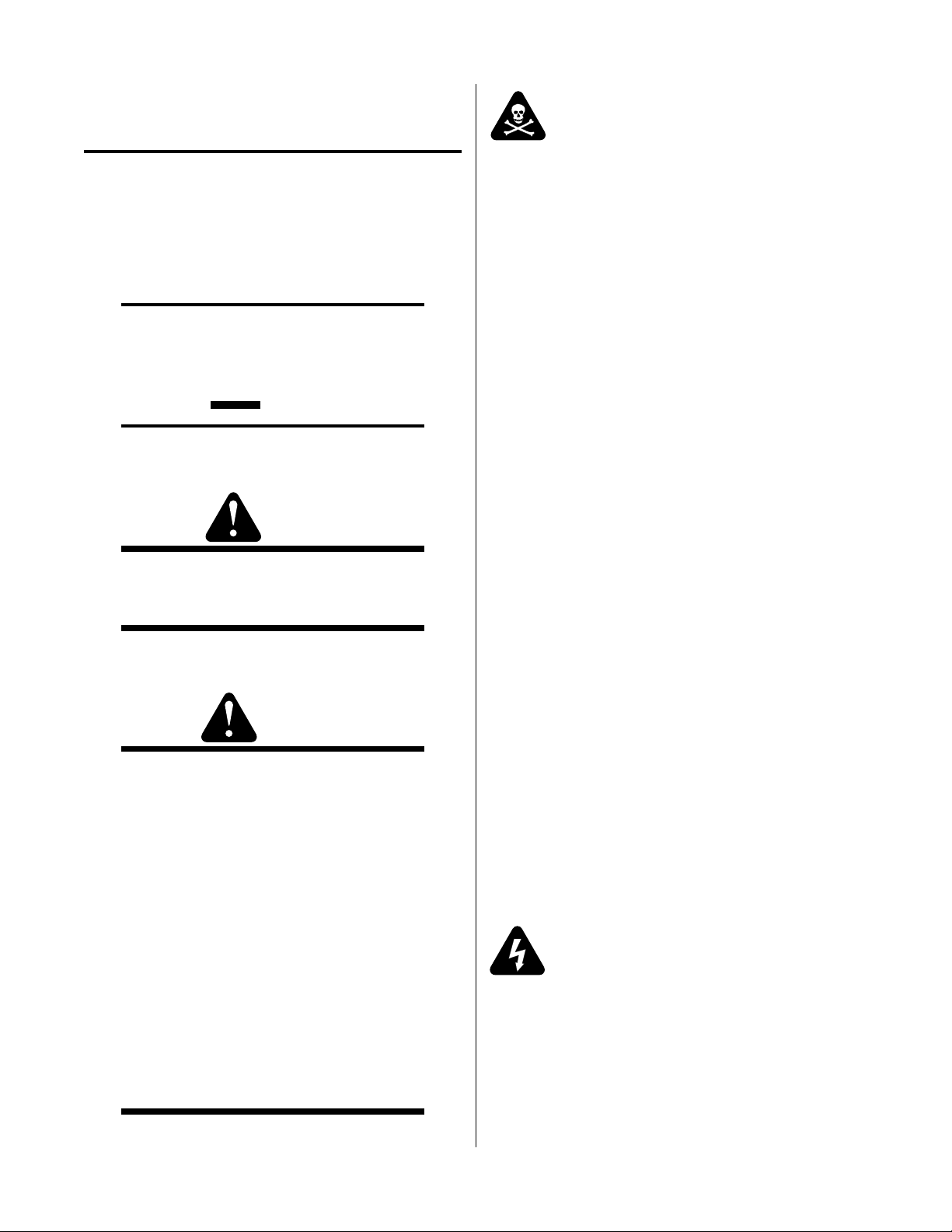
2.04 Power Supply Features
Handle and Leads Wrap
Art # A-03578
Control Panel
Torch Leads Receptacle
Gas Pressure Gauge
Work Cable
and Clamp
Gas Pressure Regulator /
Filter Assembly
Gas Inlet Port
A-03739
Input Power Cord
Manual 0-4601 2- 3 INTRODUCTION
Page 18

2.05 Power Supply Options
Section 6, Parts Lists, provides catalog numbers and ordering information.
A. Single-Stage Air Filter Kit
For use with compressed air shop systems. Filters
moisture and particulate matter from the air stream to
at least 0.85 microns.
B. Two-Stage Air Filter Kit
This two-stage air filter is for use on compressed air
shop systems. Filter removes moisture and contaminants to at least 5 microns. The filter assembly is preassembled at the factory and need only be attached to
the power supply .
C. Multi-Purpose Cart
Rugged steel cart on easy-rolling rear wheels and frontmounted swivel casters. Provides maximum mobility
for the power supply and can also serve as a display
cart. Top shelf is 12 " (305 mm) x 20 (508 mm). Steel
handle is 30" (762 mm) high.
INTRODUCTION 2-4 Manual 0-4601
Page 19

SECTION 3: INSTALLATION
3.1 Unpacking
1. Use the packing lists to identify and account for each item.
2. Inspect each item for possible shipping damage. If damage is evident, contact your distributor and / or shipping
company before proceeding with the installation.
3. Record Power Supply and Torch model and serial numbers, pur chase date and vendor name, in the information
block at the front of this manual.
3.2 Lifting Options
The Power Supply includes a handle for hand lifting only. Be sure unit is lifted and transported safely and securely.
WARNINGS
Do not touch live electrical parts.
Disconnect input power cord before moving unit.
FALLING EQUIPMENT can cause serious personal injury and can damage equipment.
HANDLE is not for mechanical lifting.
• Only persons of adequate physical strength should lift the unit.
• Lift unit by the handle, using two hands. Do not use straps for lifting.
• Use optional cart or similar device of adequate capacity to move unit.
• Place unit on a proper skid and secure in place before transporting with a fork lift or other vehicle.
Manual 0-4601 3-1 INST ALLATION
Page 20

3.3 Primary Input Power Connections
CAUTION
Check your power source for correct voltage before plugging in or connecting the unit. The primary power sour ce,
fuse, and any extension cords used must conform to local electrical code and the recommended circuit pr otection and
wiring requirements as specified in Section 2.03.
This power supply includes a factory - installed input power cable and plug.
1. Check your power source for correct voltage before plugging in the unit.
2. Connect the input power cable (or close the main disconnect switch) to supply power to the system.
CAUTION
The primary power source and power cable must conform to local electrical code and the recommended circuit
protection and wiring requirements (refer to table in Appendix 1).
INST ALLATION 3-2 Manual 0-4601
Page 21

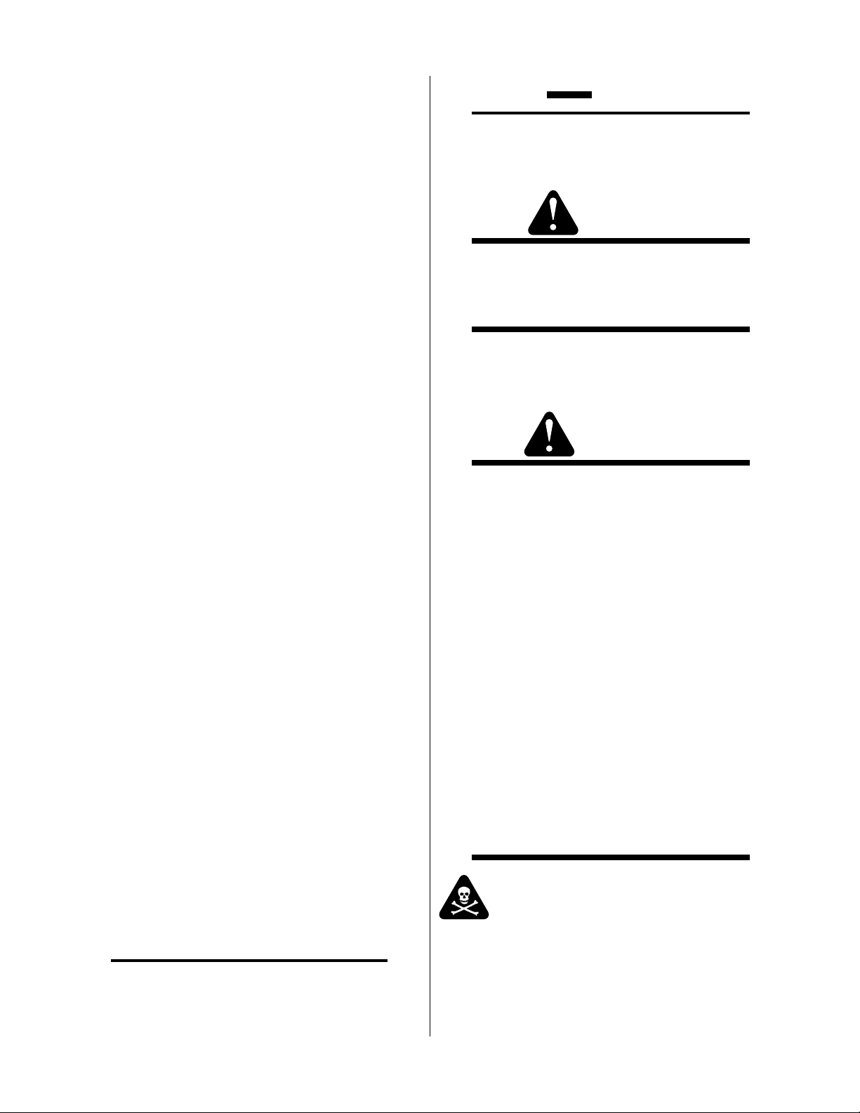
3.4 Gas Connections
A. Connecting Gas Supply to Unit
The connection is the same for compressed air or high pressure cylinders. Refer to subsection 3.4-B if a single-stage
air line filter is to be installed.
1. Connect the air line to the inlet port. The illustration shows typical fittings as an example. Other fittings may be
used.
NOTE
For a secure seal, apply thread sealant to the fitting threads, according to manufacturer's instructions. Do not use
T eflon tape as a thr ead sealer , as small particles of the tape may br eak off and block the small air passages in the torch.
Regulator/Filter
Assembly
Inlet Port
Bowl
1/4 NPT to 1/4"
(6mm) Fitting
Hose Clamp
Art # A-02999
Air Connection to Inlet Port
Gas Supply
Hose
Manual 0-4601 3-3 INST ALLATION
Page 22

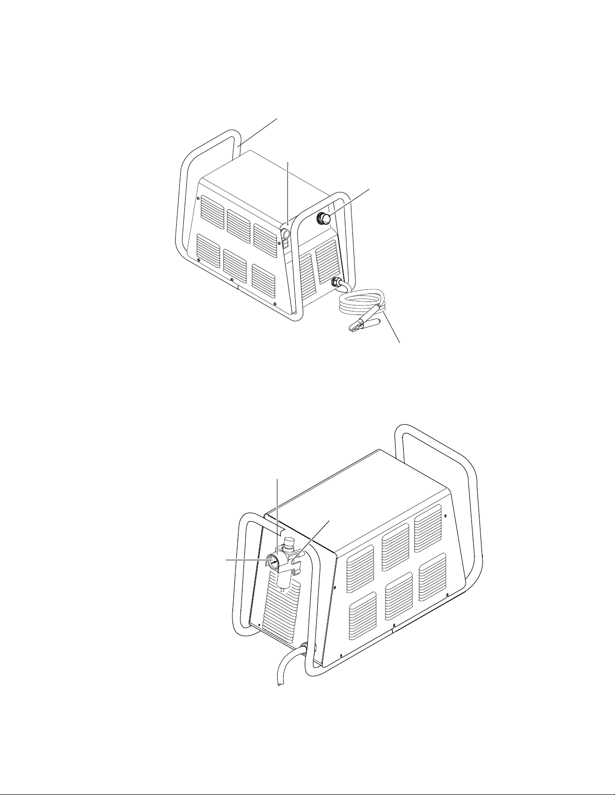
B. Installing Optional Single - Stage Air Filter
Additional filtering is recommended when using air from a compressor to insure that moisture and debris from the
supply hose do not enter the torch. Although the Pr essure Regulator does have its own filter , the optional Single-Stage
Air Filter is recommended for improved filtering. The in-line filter is highly effective at removing moisture and particulate matter from the air stream to at least 0.85 microns.
1. Attach the Single - Stage Filter Hose to the Inlet Port.
2. Attach the Filter Assembly to the filter hose.
3. Connect the air line to the Filter. The illustration shows typical fittings as an example. Other fittings may be used.
NOTE
For a secure seal, apply thread sealant to the fitting threads, according to the maker's instructions. Do Not use
T eflon tape as a thr ead sealer , as small particles of the tape may br eak off and block the small air passages in the torch.
Connect as follows:
Regulator/Filter
Assembly
Bowl
1/4 NPT Hose Fitting
Hose Clamp
1/4" (6 mm) Gas Supply Hose
Single - Stage Filter Installation
Inlet Port
Art # A-03000
INST ALLATION 3-4 Manual 0-4601
Page 23

C Using High Pressure Air Cylinders
When using high pressure air cylinders as the air supply:
1. Refer to the manufacturer’s specifications for installation and maintenance procedures for high pressur e r egulators.
2. Examine the cylinder valves to be sure they are clean and free of oil, grease or any foreign material. Briefly open
each cylinder valve to blow out any dust which may be present.
3. The cylinder must be equipped with an adjustable high - pressure regulator capable of outlet pressures up to 100
psi (6.9 bar) maximum and flows of at least 300 scfh (141.5 lpm).
4. Connect supply hose to the cylinder.
NOTE
Pressure should be set at 100 psi (6.9 bar) at the high pressur e cylinder regulator .
Supply hose must be at least 1/4 inch (6 mm) I.D.
For a secure seal, apply thread sealant to the fitting threads, according to manufacturer's instructions. Do Not use
T eflon tape as a thr ead sealer , as small particles of the tape may br eak off and block the small air passages in the torch.
Manual 0-4601 3-5 INST ALLATION
Page 24

3.5 Torch Connections
If necessary , connect the torch to the Power Supply. Connect only the model SL60 torch (with ATC connector) to this
power supply.
WARNING
Disconnect primary power at the source before connecting the torch.
1. Align the ATC male connector (on the torch lead) with the female receptacle. Push the male connector into
the female receptacle. The connectors should push together with a small amount of pressure.
2. Secure the connection by turning the locking nut clockwise until it clicks. DO NOT use the locking nut to pull
the connection together . Do not use tools to secur e the connection.
3. The system is ready for operation.
ATC Female Receptacle
Art # A-03825
Connecting the Torch to the Power Supply
ATC Male
Connector
Torch Leads
1
2
INST ALLATION 3-6 Manual 0-4601
Page 25

B. Check Air Quality
To test the quality of air:
1. Put the ON / OFF switch in the ON (up) position.
2. Put the RUN / RAPID AUTO RESTART / SET switch in the SET (down) position.
3. Place a welding filter lens in front of the torch and turn on the air . Any oil or moisture in the air will be visible
on the lens. Do not start an arc!
A
30
25
35
1
20
40
2
A-03690
Manual 0-4601 3-7 INST ALLATION
Page 26

INST ALLATION 3-8 Manual 0-4601
Page 27

SECTION 4: OPERATION
4.01 Front Panel Controls and Indicators
(A) Output Current Control
Sets the desired output current. Output settings up
to 40 Amps may be used for drag cutting (with the
torch tip contacting the workpiece) or standoff cutting.
AC Indicator
Steady light indicates power supply is ready for
operation. Blinking light indicates unit is in protective interlock mode. Shut unit off, shut off or
disconnect input power, correct the fault, and restart the unit. Refer to Section 5 for details.
TEMP Indicator
A
30
25
20
ON / OFF Switch
Controls input power to the power supply. Up
is ON, down is OFF.
35
40
A-03742
RUN / RAPID AUTO RESTART / SET Switch
Indicator is normally OFF . Indicator is ON when
internal temperature exceeds normal limits. Shut
unit OFF; let the unit cool before continuing operation.
GAS Indicator
Indicator is ON when minimum input gas pressure for power supply operation is present. Minimum pressure for power supply operation is not
sufficient for torch operation.
DC Indicator
Indicator is ON when DC output circuit is active.
RUN (up) position is for general torch operation.
RAPID AUTO RESTART (middle) position is for an uninterr upted r estart,
when cutting expanded metal or in gouging or trimming operations.
SET (down) position is for setting gas pressure and purging lines.
Manual 0-4601 4-1 OPERATION
Page 28

4.02 Preparations for Operation
At the start of each operating session:
WARNING
Disconnect primary power at the source before assembling or disassembling power supply , torch parts, or tor ch and
leads assemblies.
A. Torch Parts Selection
Check the torch for proper assembly and appropriate tor ch parts. The torch parts must correspond with the type
of operation, and with the amperage output of this Power Supply (40 amps maximum). Refer to Section 6.05 for
torch parts selection.
B. Torch Connection
Check that the torch is properly connected. Only the model SL60 torch may be connected to this Power Supply.
C. Check Primary Input Power Source
1. Check the power source for proper input voltage. Make sure the input power source meets the power requirements for the unit per Section 2, Specifications.
2. Connect the input power cable (or close the main disconnect switch) to supply power to the system.
D. Air Source
Ensure source meets requirements (refer to Section 2). Check connections and turn air supply on.
E. Connect Work Cable
Clamp the work cable to the workpiece or cutting table. The area must be free fr om oil, paint and rust. Connect
only to the main part of the workpiece; do not connect to the part to be cut off.
A-03387
OPERA TION 4-2 Manual 0-4601
Page 29

F. Power On
Place the Power Supply ON / OFF switch to the ON (up) position. AC indicator turns on. Gas indicator
turns on if there is sufficient gas pressure for power supply operation.
NOTE
Minimum pressure for power supply operation is lower than minimum for torch operation.
A
30
25
35
20
40
A-03746
Manual 0-4601 4-3 OPERATION
Page 30

G. Set Operating Pressure
1. Place the Power Supply RUN / Rapid Auto Restart / SET switch to the SET (down) position. Gas will flow.
A
30
25
35
1
20
2. Adjust gas pressure to 75 psi /5.2 bar.
Firepower P C-500
Air P r essu re S ettin g s
Leads
Length
20' / 6.1 m
SL60
Hand Torch
75 psi
5.2 bar
40
2
A-03690
75 psi / 5.2 bar
Pressure Control Knob /
Bouton De Contrôle
de Pression
Art # A-03830
OPERA TION 4-4 Manual 0-4601
Page 31

H. Select Current Output Level
1. Place RUN / Rapid Auto Restart / SET to RUN (up) or Rapid Auto Restart (center) position. Gas flow stops.
2. Set the output current output level.
2
25
A
30
35
1
20
A-03747
I. Cutting Operation
Refer to the manual supplied with the torch for details on cutting operation, cutting speeds, parts selection and
replacement, etc.
When the torch leaves the workpiece during cutting operations with the RUN / Rapid Auto Restart / SET switch
in the RUN (up) position, there is a brief delay in restarting the pilot arc. With the switch in the 'Rapid Auto
Restart' (middle) position, when the torch leaves the workpiece the pilot arc restarts instantly, and the cutting arc
restarts instantly when the pilot arc contacts the workpiece. Use the 'Rapid Auto Restart' position when cutting
expanded metal or gratings, or in gouging or trimming operations when an uninterrupted restart is desired.
40
J. Typical Cutting Speeds
Cutting speeds vary according to torch output amperage, the type of material being cut, and operator skill. Refer
to the Torch Manual for details.
Output current setting or cutting speeds may be reduced to allow slower cutting when following a line, or using
a template or cutting guide, while still producing cuts of excellent quality.
Manual 0-4601 4-5 OPERATION
Page 32

K. Postflow
Release the trigger to stop the cutting arc. Gas continues to flow for approximately 6 seconds. During post - flow,
if the user moves the trigger release to the rear and presses the trigger, the pilot arc starts. The main arc transfers
to the workpiece if the torch tip is within transfer distance to the workpiece.
L. Shutdown
T urn the ON / OFF switch to OFF (down). All Power Supply indicators shut off. Unplug the input power cord
or disconnect input power. Power is removed from the system.
A
30
25
35
20
A-03748
40
OPERA TION 4-6 Manual 0-4601
Page 33

SECTION 5:
SERVICE
5.01 General Maintenance
A. O-Ring Lubrication
An o-ring on the T orch A TC Male Connector requires lubrication on a scheduled basis. This will allow the o-ring to
remain pliable and provide a proper seal. The o-ring will dry out, becoming hard and cracked, if the o-ring lubricant
is not used on a regular basis. This can lead to potential performance problems.
It is recommended to apply a very light film of o-ring lubricant (Catalog # 8-4025) to the o-ring on a weekly basis.
NOTE
DO NOT use other lubricants or grease, they may not be designed to operate within high temperatures or may contain
“unknown elements” that may react with the atmosphere. This reaction can leave contaminants inside the torch.
Either of these conditions can lead to inconsistent performance or poor parts life.
ATC Male Connector
Gas Fitting
Art #A-03791
Manual 0-4601 5- 1 SER VICE
O-Ring
Page 34

B. Filter Element Replacement
The Regulator/Filter Assembly is on the rear panel. For better system performance, the Regulator/Filter Assembly filter
element should be checked per the Maintenance Schedule (Appendix 3), and either cleaned or replaced.
1. Remove power from the power supply; turn off the gas supply and bleed down the system.
2. Unscrew the bowl on the bottom of the Regulator/Filter Assembly. The filter element will be visible and still
attached to the main body of the Regulator/Filter .
3. Grasp the filter element and unscrew it from the Regulator/Filter body. The filter element will come off with a
spool and some additional pieces.
4. Note the correct assembly of the filter/spool then remove the filter from the spool and either clean it or replace
it.
5. The filter element and spool, with the baffle ring in place (teeth facing downward) can be screwed back into the
Regulator body by compressing the spring on the spool. T ighten firmly by hand.
Regulator/Filter
Assembly
Baffle
Ring
6. Reinstall the bowl.
7. Turn on the air supply.
Filter
Element
No. 9-4414
Spring
Spool
Bowl
Art # A-02995
Regulator/Filter Element Replacement
SERVICE 5-2 Manual 0-4601
Page 35

C. Single-Stage Filter Element Replacement
These instructions apply to power supplies where the optional Single-Stage Filter has been installed.
The Power Supply shuts down automatically when the Filter Element becomes completely saturated. The Filter
Element can be removed from its housing, dried, and reused. Allow 24 hours for Element to dry . Refer to Section 6, Parts
List, for replacement filter element catalog number .
1. Remove power from power supply .
2. Shut off air supply and bleed down system before disassembling Filter to change Filter Element.
3. Disconnect gas supply hose.
4. Turn the Cover counter-clockwise and r emove it from the Filter Housing. The Filter Element is located inside the
Housing.
Housing
Filter
Element
(Cat. No. 9-7741)
Spring
O-ring
(Cat. No. 9-7743)
Cover
Barbed
Fitting
Assembled Filter
Art # A-02476
Single-Stage Filter Element Replacement
5. Remove the Filter Element from the Housing and set Element aside to dry .
6. Wipe inside of housing clean, then insert the replacement Filter Element open side first.
7. Replace Housing on Cover.
8. Reattach gas supply.
NOTE
If unit leaks between housing and cover , inspect the "O" Ring for cuts or other damage.
Manual 0-4601 5- 3 SER VICE
Page 36

5.02 Common Faults
1. Insufficient Penetration
a. Cutting speed too fast
b. T or ch tilted too much
c. Metal too thick
d. Worn torch parts
e. Cutting current too low
f. Non - Genuine Firepower parts used
g. Incorrect gas pressure
2. Main Arc Extinguishes
a. Cutting speed too slow
b. Torch standoff too high from workpiece
c. Cutting current too high
d. Work cable disconnected
e. Worn torch parts
f. Non - Genuine Firepower parts used
3. Excessive Dross Formation
a. Cutting speed too slow
b. Torch standoff too high from workpiece
c. Worn torch parts
d. Improper cutting current
e. Non - Genuine Firepower parts used
f. Incorrect gas pressure
4. Short Torch Parts Life
a. Oil or moisture in air source
b. Exceeding system capability (material too thick)
c. Excessive pilot arc time
d. Gas pressure too low
e. Improperly assembled torch
f. Non - Genuine Firepower parts used
5. Difficult Starting
a. Worn torch parts
b. Non - Genuine Firepower parts used
c. Incorrect gas pressure
SERVICE 5-4 Manual 0-4601
Page 37

5.03 Basic Troubleshooting Guide
W ARNING
There are extremely dangerous voltage and power levels present inside this unit. Do not attempt to diagnose or repair
unless you have had training in power electronics measurement and troubleshooting techniques.
A. Basic Tr oubleshooting: Overview
This guide covers basic troubleshooting. It is helpful for solving many of the common problems that can arise with this
system. If major complex subassemblies are faulty , the unit must be r eturned to an authorized service center for repair .
Follow all instructions as listed and complete each section in the order presented.
For major troubleshooting and parts replacement procedures refer to the Power Supply Service Manual for this prod-
uct.
B. How to Use This Guide
The following information will help the Customer / Operator determine the most likely causes for various symptoms.
Follow all instructions as listed and complete each section in the order presented.
This guide is set up in the following manner:
X. Symptom (Bold Type)
Any Special Instructions
1. Cause
a. Check / Remedy
Locate your symptom, check the causes (easiest listed first), then remedies. Repair as needed being sure to verify that
unit operates properly after any repairs.
C. Common Symptoms
A. AC indicator OFF
1. Switch at main power panel in OFF (open) position.
a. Close main power switch.
2. Power Supply ON / OFF switch in OFF (down) position.
a. Turn switch to ON (up).
3. Tor ch is not connected properly to Power Supply
a. Turn power supply ON / OFF switch to OFF (down). Check torch connection to Power Supply. Tighten or
adjust as required. Do not use tools. Turn power supply ON / OFF switch to ON (up).
4. Shield cup not fully tightened on torch head
a. Check shield cup for proper installation. Do not overtighten. Do not use tools to tighten.
NOTE
When operating the torch in a normal condition, a small amount of gas vents through the gap between the shield cup and
torch handle. Do not attempt to over tighten the shield cup as irreparable damage to internal components may result.
5. Main power line fuse(s) or circuit breaker(s) blown
a. Check main power panel fuse(s). Replace as required.
Manual 0-4601 5- 5 SER VICE
Page 38

6. Unit internal fuse blown or loose
a. If blown, double-check input voltage and replace fuse per Section 5.04-C. If fuse blows again, return unit to
an authorized service center .
7. Actual input voltage does not correspond to voltage of unit
a. Verify that the input line voltage is corr ect. Refer to Section 2, Input W iring Requirements.
8 . Faulty components in unit
a. Return for repair or have qualified technician repair per Service Manual.
B. Gas flows continuously when power is turned on, AC indicator flashes
1. Tor ch switch is activated (closed) before user turns power on.
a. Release torch switch.
2. Faulty torch switch
a. Check torch switch for continuity . Replace if necessary.
C. Gas flows continuously; T orch will not pilot when torch switch is activated; AC indicator ON
1. System is in SET mode
a. Change RUN / Rapid Auto Restart / SET switch to Rapid Auto Restart (center) or RUN (up) position.
D. No gas flow; RUN / Rapid Auto Restart / SET switch in SET position; Fans operate; AC indicator ON;
GAS indicator OFF
1. Gas not connected
a. Check gas connections.
2. Gas pressure too low for power supply operation
a. Adjust gas pressure per gas pressure label on power supply.
3. Faulty components in unit
a. Return for repair or have qualified technician repair .
E. T orch will not pilot; gas flows; AC indicator ON, GAS , TEMP , and DC indicators OFF
1. Gas pressure is below power supply minimum requirement.
a. Adjust pressure to 75 psi / 5.2 bar .
F . T orch will not pilot; gas flows; AC and Gas indicators ON; DC and TEMP indicators OFF
1. Gas pressure is below torch minimum requirement (Minimum pressure for power supply operation is lower than mini-
mum required for torch operation.)
a. Adjust pressure to 75 psi / 5.2 bar .
SERVICE 5-6 Manual 0-4601
Page 39

G. Torch will not pilot; no gas flow; AC indicator ON, GAS indicator ON, DC indicator ON
1. Starter cartridge missing from torch
a. Shut off power supply . Remove shield cup, install starter cartridge. Reinstall torch tip and shield cup. T urn
power supply ON / OFF switch to ON (up).
2. Shield cup is loose on torch
a. Check shield cup; tighten if necessary.
NOTE
When operating the torch in a normal condition, a small amount of gas vents through the gap between the shield cup and
torch handle. Do not attempt to over tighten the shield cup as irreparable damage to internal components may result.
3. T orch head upper O-ring on tor ch head is in wrong position.
a. Remove shield cup from torch; check position of upper O-ring. Correct if necessary .
Art # A-03640
Upper Groove
with V ent Holes
Must Remain Open
Upper O-Ring
in Correct Groove
Threads
Lower O-Ring
H. Torch will not pilot; AC , GAS , and TEMP indicators ON, DC indicator OFF
1. Air flow blocked
a. Check for blocked air flow around the unit and correct condition.
2. Unit is overheated
a. Let unit cool down for at least 5 minutes. Make sure the unit has not been operated beyond Duty Cycle limit.
Refer to duty cycle data in Section 2.
3. Input line voltage is low
a. Check and connect to proper input power line.
4. Faulty components in unit
a. Return for repair or have qualified technician repair per Service Manual.
Manual 0-4601 5- 7 SER VICE
Page 40

I. Torch cannot be activated; AC indicator flashing; Gas indicator ON; T emp indicator OFF; DC
indicator OFF
1. System is in protective interlock mode. (User held torch trigger while turning on ON / OFF switch.)
a. Release torch trigger.
2. System is in protective interlock mode. (T orch parts are missing or loose.)
a. Release torch trigger, and set power supply ON / OFF switch to OFF (down). Open main disconnect switch.
Check torch parts. Replace parts as needed. Reinstall shield cup; hand - tighten it securely against the torch
head. Do not overtighten. Do not use tools. Close main disconnect switch. Set ON / OFF switch to ON (up)
position.
NOTE
When operating the torch in a normal condition, a small amount of gas vents through the gap between the shield cup and
torch handle. Do not attempt to over tighten the shield cup as irreparable damage to internal components may result.
J. Gas cycles on and off without torch switch being activated; AC indicator
ON; DC indicator OFF
1. T orch tip or electrode missing
a. Shut off power supply . Remove shield cup, install missing part(s). T urn power supply ON / OFF switch to
ON (up).
K. No cutting output; T orch pilots; Gas flows; Fans operate; AC ,Gas , and DC indicator ON;
TEMP indicator OFF
1. Work cable not connected to work piece, or connection is poor
a. Make sure that work cable has a proper connection to a clean, dry area of the workpiece.
2. Faulty T orch
a. Return for repair or have qualified technician repair .
3. Faulty components in unit
a. Return for repair or have qualified technician repair per Service Manual.
L. T orch cuts but not adequately
1. Incorrect setting of output current (A) control
Flashing; Gas indicator
a. Check and adjust to proper setting.
2. Torch consumables worn
a. Check torch consumables per Tor ch manual; replace as needed.
3. Work cable connection to work piece is poor
a. Make sure that work cable has a proper connection to a clean, dry area of the workpiece.
4. T orch is being moved too fast across workpiece
a. Reduce cutting speed.
SERVICE 5-8 Manual 0-4601
Page 41

5. Excessive oil or moisture in torch
a. Put RUN / RAPID AUTO REST ART / SET switch in SET (down) position. Hold torch 1/8 inch (3 mm) from
clean surface while purging and observe oil or moisture buildup (do not activate torch). If there are contaminants in the gas, additional filtering may be needed.
6. Fluctuations in input power
a. Have electrician check input line voltage.
7. Faulty components in unit
a. Return for repair or have qualified technician repair per Service Manual.
M. Arc shuts off during operation; arc will not restart when torch switch is activated.
1. Power Supply is overheated (TEMP
a. Let unit cool down for at least 5 minutes. Make sure the unit has not been operated beyond Duty Cycle limit.
Refer to Section 2 for duty cycle specifications.
2. Fan blades blocked (TEMP
a. Check and clear blades.
3. Air flow obstructed (TEMP indicator ON)
a. Check for obstructed air flow around the unit and correct condition.
4. Gas pressure too low (GAS indicator OFF when torch switch is activated)
a. Check source for at least 60 psi / 4.1 bar; adjust as needed. (Minimum pressure for power supply operation
is lower than minimum required for torch operation.)
5. Torch consumables worn
a. Check torch consumables per Tor ch manual; replace as needed.
6. Faulty components in unit
a. Return for repair or have qualified technician repair per Service Manual.
indicator ON)
indicator ON)
N. AC indicator remains ON when shield cup is removed
1. Faulty PIP switch in torch
a. Check PIP switch for continuity; replace if necessary
Manual 0-4601 5- 9 SER VICE
Page 42

5.04 Power Supply Basic Parts Replacement
W ARNING
Disconnect primary power to the system before disassembling the torch, leads, or power supply.
This section describes procedures for basic parts replacement. For more detailed parts replacement procedures, refer to
the Power Supply Service Manual.
A. Cover Removal
1. Remove the upper screws which secure the cover to the main assembly .
NOTE
There is a ground wire connection to the inside of the unit. There is no need to disconnect the ground wire, unless there
is a need for more room to work.
Upper
screws
Lower
screws
Art # A-03939
Lower
screws
Ground wire
2. Loosen, but do not remove, the lower screws, then carefully pull the Cover up and away from the unit.
SERVICE 5-10 Manual 0-4601
Page 43

B. Cover Installation
1. Reconnect the ground wire, if necessary .
2. Place the cover onto the power supply so that slots in the bottom edges of the cover engage the lower screws.
3. Tighten lower screws.
4. Reinstall and tighten the upper screws.
C. Fuse Replacement
1. Remove the unit cover per paragraph "A" above.
2. Locate the internal fuse on the left side of the center chassis.
3. Replace the fuse. A replacement fuse is located inside the power supply. Refer to Section 6, Parts Lists, for
replacement fuse catalog number .
4. Reinstall the cover by reversing the steps in paragraph "B" above.
Internal Fuse Location
This completes the parts replacement procedures.
Fuse Location
Art # A-03002
Manual 0-4601 5-11 SERVICE
Page 44

SERVICE 5-12 Manual 0-4601
Page 45

SECTION 6:
PARTS LISTS
6.01 Introduction
A. Parts List Breakdown
The parts list provide a breakdown of all replaceable components. The parts lists are arranged as follows:
Section 6.03 Complete Power Supply Replacement
Section 6.04 Power Supply Replacement Parts
Section 6.05 Torch Replacement Parts
NOTE
Parts listed without item numbers are not shown, but may be ordered by the catalog number shown.
B. Returns
If a product must be returned for service, contact your distributor . Materials returned without pr oper authorization
will not be accepted.
6.02 Ordering Information
Order replacement parts by catalog number and complete description of the part or assembly, as listed in the parts
list for each type item. Also include the model and serial number of the power supply. Address all inquiries to your
authorized distributor .
6.03 Power Supply Replacement
The following items are included with the replacement power supply: work cable & clamp, input power cable, gas
pressure regulator / filter, and operating manual.
Qty Description Catalog #
1 Firepower Model PC-500 Power Supply, 208 / 230VAC, Single - Phase, 1145-0945
60Hz, with input power cable and plug
Manual 0-4601 6-1 P A RTS LISTS
Page 46

6.04 Replacement Parts
Qty Description Catalog #
1 Fuse 9-8110
1 Standard Regulator / Filter Assembly Replacement Element 9-4414
1 Single - Stage Filter Kit (includes Filter & Hose) 1445-0080
1 Replacement Filter Body 9-7740
1 Replacement Filter Hose (not shown) 9-7742
2 Replacement Filter Element 9-7741
1 T wo - Stage Filter Kit (includes Hose & Mounting Scr ews) 1445-0914
1 Bracket, Filter Mounting (not shown) 9-7535
1 T wo - Stage Air Filter Assembly 9-7527
1 First Stage Cartridge 9-1021
1 Second Stage Cartridge 9-1022
1 Multi - Purpose Cart (not shown) 1445-0913
1
Housing
Filter
Element
(Cat. No. 9-7741)
Spring
O-ring
(Cat. No. 9-7743)
Cover
Barbed
Fitting
Single - Stage Filter Kit Two - Stage Filter Kit
Assembled Filter
Art # A-02476
First & Second
Stage
Cartridges
(as marked)
Art # A-02942
PARTS LISTS 6-2 Manual 0-4601
Page 47

6.05 Torch Parts
Art # A-03826
Large O-Ring,
No. 1445-0040
Small O-Ring,
No. 1445-0048
Electrode, No. 1445-0049
Starter Cartridge, No. 1445-0054
40 Amp Cutting Tip, No. 1445-0923
Shield Cup, No. 1445-0083
Worn Electrode
Worn Tip
Manual 0-4601 6-3 P A RTS LISTS
Page 48

PARTS LISTS 6-4 Manual 0-4601
Page 49

APPENDIX 1: SEQUENCE OF OPERATION
(BLOCK DIAGRAM)
ACTION:
Close external
disconnect switch.
RESULT:
Power to system.
Connect work cable to workpiece.
Set output amperage.
System is ready
for operation.
ON / OFF switch to ON
AC indicator ON.
GAS indicator ON
pressure is adequate
for power supply operation.
ACTION:
RESULT:
ACTION:
RESULT:
Fan(s) ON.
when input
Power circuit ready.
ACTION:
RUN /
Rapid Auto Restart /
SET switch
to SET
RESULT:
Gas flows to set pressure.
Torch moved away from work (while
ACTION:
RUN /
Rapid Auto Restart / SET
switch to RUN
(for most applications)
or to
Rapid Auto Restart
(for gouging, trimming,
or expanded metal
applications)
RESULT:
Gas flow stops.
ACTION:
still activated).
RESULT:
ACTION:
Protect eyes and activate torch.
RESULT:
Gas flows briefly, then stops.
Gas restarts.
DC indicator ON
Pilot arc established.
ACTION:
Release torch trigger.
RESULT:
Main arc stops.
Gas flow stops after post - flow.
PILOT ARC
ACTION:
ON / OFF switch
to OFF
RESULT:
All indicators off.
Power supply fan(s) shuts off.
Main arc stops.
Pilot arc automatically
restarts.
ACTION:
Torch moved within
transfer distance of workpiece.
RESULT:
Main arc transfers.
Pilot arc off.
ACTION:
Unplug input
power cord or
open external
disconnect.
RESULT:
No power to system.
Art #A-03706A
Manual 0-4601 A-1 APPENDIX
Page 50

APPENDIX 2: DATA TAG INFORMATION
Type of Power
Supply (Note 1)
Plasma Cutting
Symbol
Input Power
Symbol
Input Power
Specifications
(Phase, AC or DC
Hertz Rating)
Model:
Date of Mfr:
1/3
f
1
f
2
Output Current Type
U
Rated NoLoad Voltage
Degree of Protection
X
=
0
U
Conventional
Load Voltage
West Lebanon, NH USA 03784
I
2
U
1
Rated Supply
Voltage (Note 2)
S/N
Made in USA
Duty Cycle Factor
Rated Maximum
Supply Current
1max 1eff
I
1
1Ø
3Ø
Manufacturer's Name and/or
Logo, Location, Model and
Revision Level, Serial Number
and Production Code
Regulatory Standard Covering
This Type of Power Supply
Output Range (Amperage/
Voltage)
Duty Cycle Data (Note 3)
I
1
3Ø1Ø
Maximum Effective
Supply Current
Manufacturer's Electrical
Schematic File Number
and Revision Level
NOTES:
1. Symbol shown indicates single- or three-phase AC input,
static frequency converter-transformer-rectifier, DC output.
2. Indicates input voltages for this power supply. Most power
supplies carry a label at the input power cord showing input
voltage requirements for the power supply as built.
3. Top row: Duty cycle values.
IEC duty cycle value is calculated as specified by
the International ElectroTechnical Commission.
TDC duty cycle value is determined under the power supply
manufacturer's test procedures.
Second row: Rated cutting current values.
Third row: Conventional load voltage values.
4. Sections of the Data Tag may be applied to separate areas
of the power supply.
Standard Symbols
AC
DC
Phase
Ø
Art # A-03288
APPENDIX A-2 Manual 0-4601
Page 51

APPENDIX 3: MAINTENANCE SCHEDULE
This schedule applies to all types of non-liquid cooled plasma cutting systems. Some systems will not have all the parts
listed and those checks need not be performed.
NOTE
The actual frequency of maintenance may need to be adjusted according to the operating environment.
Daily Operational Checks or Every Six Cutting Hours:
1. Check torch consumable parts, replace if damaged or worn.
2. Inspect torch for any cracks or exposed wires, replace if necessary .
3. Check plasma and secondary supply and pressure/flow.
4. Purge plasma gas line to remove any moisture build-up.
5. Inspect input power cable for damage or exposed wires, replace if necessary .
Weekly or Every 30 Cutting Hours:
1. Check fan for proper operation and adequate air flow .
2. Blow or vacuum dust and dirt out of the entire machine.
CAUTION
Do not blow air into the power supply during cleaning. Blowing air into the unit can cause metal particles to interfere
with sensitive electrical components and cause damage to the unit.
Six Months or Every 720 Cutting Hours:
1. Check the in-line air filter(s), clean or replace as required
2. Check cables and hoses for leaks or cracks, replace if necessary .
3. Check all contactor points for severe arcing or pits, replace if necessary .
Manual 0-4601 A-3 APPENDIX
Page 52

APPENDIX 4: TORCH PIN - OUT DIAGRAM
Negative /
Plasma
4 - Green /
Switch
3 - White /
Switch
2- Orange /
PIP
1 - Black /
PIP
Pilot
ATC Male Connector
Front View
4
3
2
1
ATC Female Receptacle
Front View
8 - Open
8
7
6
5
7 - Open
6 - Open
5 - Open
8 - Ground
7 - Open
6 - Open
5 - Open
Pilot
8
7
6
5
2
1
Negative /
Plasma
4 - Switch
3 - Switch
4
3
2 - PIP
1 - PIP
A-03701
APPENDIX A-4 Manual 0-4601
Page 53

APPENDIX 5: TORCH CONNECTION DIAGRAM
Torch: SL60 / SL100 Hand Torch
Leads: Torch Leads with ATC Connector
Po wer Supply: with ATC Receptacle
Torch
Head
PIP
Switch
Torch
Switch
Torch
Leads
Black
Orange
Green
White
Negative / Plasma
Pilot
Male
ATC Leads
Connector
ATC Female
Receptacle
1
2
5
6
4
3
8
7
1
2
5
6
4
3
8
7
Power
Supply
To Power Supply
Circuitry
To Power Supply
Circuitry
Negative / Plasma
Pilot
Art # A-03797
Manual 0-4601 A-5 APPENDIX
Page 54

APPENDIX 6: SYSTEM SCHEMATIC
1
2
3
4
E6
E8
5
E5
CHASSIS
GND
(3)
(4)
(6)
(5)
(21)
(22)
(23)
(24)
(25)
(26)
J14
(35)
1
1
(36)
2
2
(37)
3
3
(38)
4
4
(39)
5
5
(40)
6
6
(41)
7
7
(42)
8
8
+12VDC
+12VDC
GND SIGNAL
GND SIGNAL
GND SIGNAL
RUN/SET
PRE SS GOOD
OVE RTEMP
GND SIGNAL
GND SIGNAL
GND SIGNAL
28VAC A
GAS ON
CSR
GND SIGNAL
DC OK
OVTEMP
AC OK
RTN
TORCH SWITCH
+12VDC
POT HIGH
POT WIPER
POT LOW
GATE DRIVE B RTN
GATE DRIVE B
GATE DRIVE A RTN
GATE DRIVE A
- OUT
CURRENT SENSE
CURRENT SENSE
ISENSE
W1
(1)
W1
(2)
P8 J8
1
2
3
4
1
1
2
2
3
3
4
4
1
2
3
4
5
6
7
8
P22P14
1
2
3
4
5
6
7
8
P2
1
2
3
4
P23 J23
121
P1
1
2
3
4
W1
5
6
7
8
9
10
10
11
11
12
12
13
13
14
14
15
15
16
16
17
17
18
18
19
19
20
20
21
21
22
22
23
23
24
24
25
25
26
26
27
27
28
28
29
29
30
30
31
31
32
32
33
33
34
34
35
35
36
36
TIP
E14
1
2
3
4
F1 ( 6/10A 600V)
R95
(0 ohm)
J26P26
K3
J3P3
1
2
3
4
5
6
7
TO BI AS SUPPLY
8
INRUSH
FAN
J22
1
POT HIGH
2
POT WIPER
3
POT LOW
4
+12V
5
AC
6
GAS
7
OVE RTEMP
8
DC
J2
1
2
3
4
2
J1
1
2
3
4
5
K2
6
7
CONTA CTOR ON
8
9
K5
SOL ENOID ON
MAIN BOARD
ASSY 19X2001
CHASSIS GND
THRU SCREW TERMINAL
E16
K4
K3
E3
(FILTERING)
K4
T1
28VAC B 28VAC A
28VAC A
28VAC B
+12V
+18V
+18V
+18V
E28
A
208 / 230V
INPUT
L1
L2
B
M1
FAN1
230V
28VAC B
28VAC A
C
D
ON/OFF SW
MODE SW
RAR OFF
(PILOT PCB) (F6)
CURRENT ADJUST:
20 - 40 AMPS
CURRENT
CONTROL/
LED PCB
19X 1604
IGBT
HEATSINK
TEMP
INDUCTOR
TEMP
SW1
RUN
SET
(46)
SW2
AC
TEMP
GAS
DC
NTC
t
TS1
TS2
E
INV ON
D8
(RED)
F
LOGIC
ASSY 19X2000
CURRENT SENSE RTN
CURRENT SENSE RTN
E2
E1
K4
TO BIAS
SUPPLY
PRE SS GOOD
E13
E18
COPPER STRAP
GATE DRIVE A RTN
GATE DRIVE B RTN
CSR
DC COMMON
K5
F2, 0.9A,
(RESETABLE)
K2
INPUT DIODE
ASSY 19X2073
GATE DRIVE A
GATE DRIVE B
TORCH SWITCH TORCH SWITCH +
CURRENT
SENSE
PIP RTN41
TORCH SW
TORCH SW RTN
28VAC A
28VAC B
ISENSE
CSR
J21
J20
Vo
GND
+12V
CSR
PIP
1
2
1
2
J9
2
3
J5
1
2
3
J4 P4
1
2
3
4
5
6
7
8
9
10
1
2
1
2
E22
1
2
3
4
1
2
3
4
5
6
7
8
9
10
E14
E16
E4
E9
E8
E20
P9
E11
E12
E13
E15
P21
P20
E35
E21
E26
E25
E23
E24
E19
E18
E5
E10
E6
E7
E17
E34
TEST
CONN
MAIN TRANSFORMER
T5
PRI
SEC
(CSR)
(TS2)
(TS1)
(NEG)
(E17)
(E34)
(78)
1
(79)
2
(80)
3
(81)
4
8
(7)
(8)
(9)
(10)
(11)
(12)
(13)
(14)
(19)
(20)
1
PIP
2
3
TORCH SW
4
8
ATC M A L E CONNECTOR
ATC RECEIVER
SOL1
W1
ATC C ONNECTION
CONF IGURATION
GAS
BA
SOLENOID
PRESSURE
SWITCH
PS1
CLOSED WHEN
PRE SSURE OK
MAIN
CONTACTOR
Art # A-03695
1
2
3
4
5
APPENDIX A-6 Manual 0-4601
Page 55

6
5
7
8
9
10
COMP DESCRIPTION LOC ATION
F1
FUSE, 6/10A 600V KTK
W1
MAIN CONTACTOR
SW1
SW ITCH, ON/OFF
SW2
SW ITCH, RUN/SET/RAR
M1
FAN, 4.5" 220VAC
SOL1
GAS SOLENOID
PS1
PRESSURE SWITCH
TS1
TEMP. SENS OR, IGBT HEATSINK
TS2
TEM P . S E NSOR, INDUCTOR
T1
AUX TRANSFORMER
T5
MA IN TRANSFORMER
L1
OUTP UT INDUCTOR
B3
F5
C2
C2
B2
F5
F5
D2
E2
B3
C5
E6
A
E38
E39
E40
E41
E28
E29
E32
E33
23
24
25
ASSY 19X1721
OUTP UT DIODE
ASSEMBLY
19X1720
12
13
14
2
4
5
6
7
IGBT BOARD
GATE
J18 P18
DRIVE
28
27
GATE
DRIVE
J19
1
E36
E37
E42
E43
OUTP UT INDUCTOR
L1
ATC RECEIVER
ATC M A L E CONNECTOR
E30
E31
NOTES: UNLESS OTHERWISE SPECIFIED
1. D EPICTIONS OF CIRCUITRY INSIDE PCB BLOCKS
2
121
P19
2
121
IS FOR REFERENCE ONLY
B
C
OPTIONAL AUTOMATION INTERFACE CONNECTIONS
ALTE RNATE 20-PIN HEADER
J1
P1
(CSR)
(NEG)
PLUGS INTO J22
*
ON MAIN BOARD
(LE D PCB 19X1604)
J14 P14
1
1
2
2
3
3
AC
4
4
5
5
6
6
TEMP
7
7
8
8
GAS
T
O
R
C
H
DC
(47)
1
(48)
2
(49)
3
4
5
6
7
8
ADAPTE R HARNESS USED
WHEN RE MOTE CURRENT
CONTR OL IS USED WITH
AUTO MATION
(REPLACES CONNECTIONS
FROM J22 TO J14)
(TS2)
(TS1)
1
1
2
3
4
5
6
7
8
P3
2112
3
CSR
2
DC COMMON
3
+12VDC
4
5
TORCH SW -
6
TORCH SW +
7
Vo
8
19X2041
OPTIONAL
AUTO MATION
INTERFACE
J3
3
P4
J4
20
20
19
19
18
18
17
17
16
16
15
15
14
14
13
13
12
12
11
11
10
10
9
9
8
8
7
7
6
6
5
5
4
4
3
3
2
2
1
1
(51)
(52)
20-P OSITION TERMINAL STRIP
J2
1
+
2
TORCH SWITCH
3
-
4
5
6
OK TO MOVE
7
8
9
+
10
DIVIDED OUTPUT
11
-
12
13
14
REM OTE CURRENT CONTROL
15
16
17
DC COMMON
18
+
19
C&G
20
-
(56)
4
(57)
3
(58)
14
(59)
12
(60)
6
(61)
5
(62)
8
(63)
9
(64)
7
CPC
HOUSING
(+)
TOR CH SWITCH
}
(-)
}
OK TO MOVE
(+)
}
SC-11
(-)
LOGIC COMMON
(+)
}
ARC VOLTS (C&G)
(-)
D
E
5
8
(46)
WORK
J1
(52)
1
(51)
2
RAR OFF
(MODE SW) (C2)
AA
ECO 101136
AB
AC
Last Modified:
7
8
Thursday, June 10, 2004
DateByRe visionsRev
(REL)
DLL 05/27/03
02 /11/04HASECO 101314
HAS 0 6/09/04ECO 101429
In for mat ion Proprietary to THERMAL DYNAMICS CORPORATION.
No t F or R elea se, Reproduction, or Distribution without Written Consent.
NOTE:
Unless Otherwise Specified, Resistors are in Ohms 1/4W 5%.
Ca paci tors are in Microfarads (UF)
TITLE:
15:05:29
9
SCHEMATIC,
CM51 208/230V SYSTEM
TH ERMAL DYNAMICS
IN DUSTRIAL PARK No. 2
WE ST LEBANON, NH 03784
603-298-5711
PCB No:
As sy No:
Date:
Drawn: Re ferences
Chk: App:
Size
D
Art # A-0369
10
05 /27/03
D.Lilja
DW G No:
SupersedesScale
Sheet
11
42X1150
F
of
(E62)
E62
PILOT BOARD
ASSY 19X2086
E58
12
3
J28
(E58)
+12V
GND
CSR
ISENSE
6
Manual 0-4601 A-7 APPENDIX
Page 56

 Loading...