

Page 1

Manual 0-4952
82 Benning Street, West Lebanon, NH 03784 USA
(603) 298-5711 • www.thermal-dynamics.com
Main PCB / Transducer Kit
Catalog# 9-9515
Gas Control Module
Installation Instructions
Unpacking
The product is packaged and protected to prevent damage during shipping. Inspect for possible shipping damage. If
damage is evident, contact your distributor and/or shipping company before proceeding with installation.
Contents
• Main PC Board for Gas Control Module
• Static handling items and instructions
• (2) Pressure Transducers/ Harness assemblies
• (2) 1/8" NPT 2 position fittings
• Installation Instructions
Applications
This product is for use only with for Thermal Dynamics Gas Control Modules 2000 and 2010. Do not use this product
with any other equipment.
© 2006 by Thermal Dynamics Corp., Printed in USA
December 7, 2006 1 Manual 0-4952 Rev. AA.01
Page 2
PC Board Removal
WARNINGS
Disconnect primary power at the source before starting the procedure.
Use caution when handling the printed circuit board as damage can result from improper handling or from electrostatic discharge. Wear appropriate static-handling equipment and grounding strap while performing this replacement procedure.
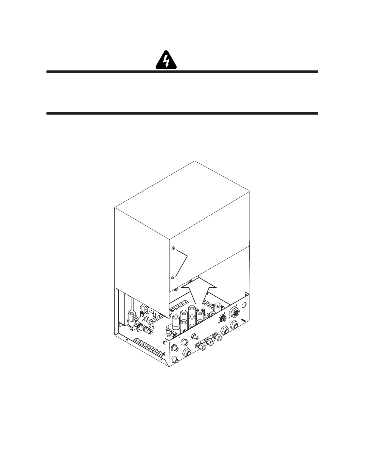
1. Remove the screws securing the cover panel to the gas control module. Save the hardware for re-use.
2. Remove the cover from the module.
Gas Control Module Cover
Do not remove
Art # A-06882
December 7, 2006 2 Manual 0-4952 Rev. AA.01
Page 3
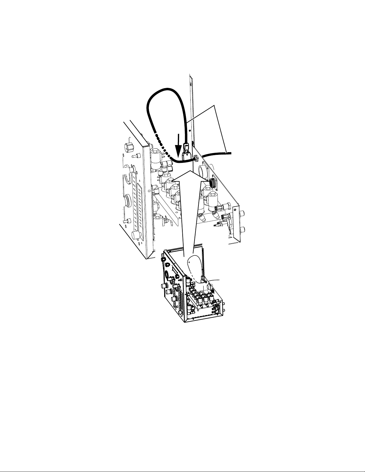
3. Disconnect the fiber-optic cable connector from the receptacle on the printed circuit board. Set the connector
aside carefully in a secure location.
Circuit Board
Fiber Optic Cable
Art # A-04773
4. Use the anti-static equipment as detailed on the instructions provided separately.
5. Wire harness connection points on the PCB are marked with a 'J' number such as "J5" or "J8". Label each wire
harness connector with this number to ensure reconnection to the correct point when installing the replacement PCB. Connection points are illustrated on the last page of these instructions. The application may not use
all connection points shown in the illustration.
6. Unplug the harnesses from the Main PCB that are easy for you to access. Leave the ones along the bottom for a
little later.
December 7, 2006 3 Manual 0-4952 Rev. AA.01
Page 4
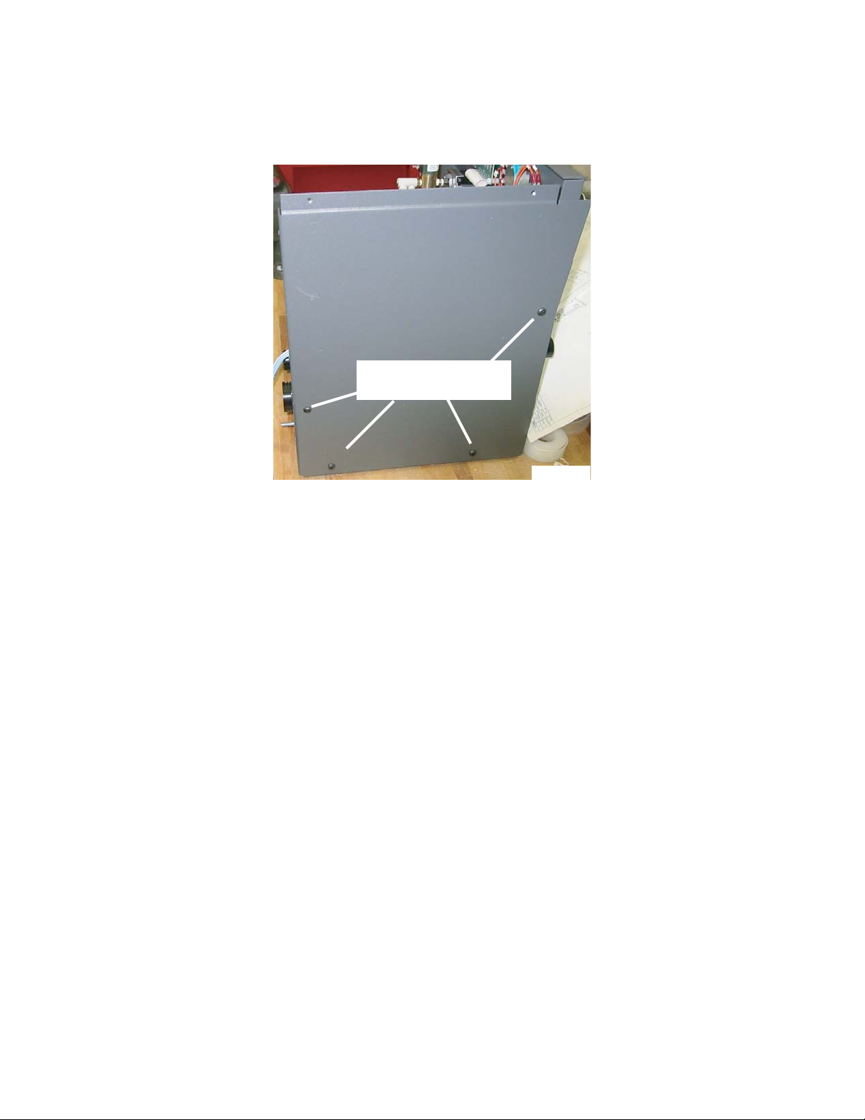
7. Disconnect the hardware fastening the side panel to the control module. Carefully pull the panel away from the
module. Any remaining harnesses connected to the PCB on the inside of the panel will restrict motion. Do not
cause any tension on these wire harnesses.
Hardware Locations
Art # A-07025
8. Carefully disconnect any remaining wire harnesses connected to the PCB. The J8 connector for the ribbon cable
includes levers at each end. Move these levers away from the ribbon cable to release the cable from the connector.
9. When all harnesses are disconnected, let the side panel and PCB assembly lie on a flat surface.
December 7, 2006 4 Manual 0-4952 Rev. AA.01
Page 5

10. Remove the hardware securing the PCB to the side panel.
Mounting Hardware Locations
Art # A-07347
11. Gently lift the PCB off the side panel and carefully set it aside.
December 7, 2006 5 Manual 0-4952 Rev. AA.01
Page 6

One Touch Fitting Replacement
1. Locate the two 90° One Touch elbow connections shown in the illustration below. Disconnect the black air
tubes from the fittings. Using an open end wrench or your fingers, depress the locking ring on the fitting and
pull the tube to release it from the fitting.
2. Remove the elbows. For the one on the right in this illustration, you will need to place an open end wrench on
the brass "T" fitting to keep it from turning while removing the elbow.
Remove 90°
fitting here
Place wrench here
Remove 90°
fitting here
to avoid movement
from this fitting while
removing 90° fitting.
One Touch Elbow removal. Some items removed for clarity.
Art # A-07616
December 7, 2006 6 Manual 0-4952 Rev. AA.01
Page 7

3. Install the two new One Touch fittings in the two locations where the last fittings were just removed. See
illustration. You will need to place an open end wrench on the brass "T" fitting to keep it from moving while
installing the new fitting on the right. Do not over tighten these fittings.
Install new
fitting here
Place wrench here
Install new
fitting here
to avoid movement
from this fitting while
installing new fitting.
Art # A-07617
New Fittings in place. Some items removed for clarity
4. Reinstall the two black tubing pieces removed in step 1, making sure they seat all the way. You should feel this
when done properly.
December 7, 2006 7 Manual 0-4952 Rev. AA.01
Page 8

Transducer Installation
1. Find the two TransducerAssemblies supplied with this kit. There will be a small black tube and a harness
attached to them. Insert the free end of the tubing into each of the other new One Touch fittings just installed. Be
careful not to press on the transducer but firmly grasp the tubing below the white clamp, pressing it into the
fitting until you feel it lock in place.
Transducers, harness and tubing
New One Touch Fittings
Art # A-07619
December 7, 2006 8 Manual 0-4952 Rev. AA.01
Page 9

PC Board Installation
CAUTION
Use the antistatic equipment according to the instructions supplied separately.
1. Carefully place the replacement PCB in position on the module side panel.
2. Use the same hardware that held the previous PCB in place and fasten the PCB to the side panel. Tighten
snugly. Do not overtighten.
Mounting Hardware Locations
Art # A-07347
Illustration is for Reference Only
December 7, 2006 9 Manual 0-4952 Rev. AA.01
Page 10

3. Refer to Illustration at the end of these instructions. Carefully reconnect all wire harnesses to the 'J' connectors
on the PCB. Refer to Step 4 for details on the harness connector for receiver J6. Close the levers on the ends of
the J8 receptacle to secure the ribbon cable in place. Check all connections for a secure fit. Some connectors
include a locking feature; align the parts as shown, press them firmly together, then check for a secure fit.
Art # A-07348
Locking Notch
Harness Connector
Receiver
Locking Rib
Harness Receiver
Align Harness Connector
and Harness Receiver
Assembled Connector
and Receiver
4. If the cable connector has fewer pins than a board receptacle, it may be necessary to trim an alignment pin off
the cable connector as shown. When joining a connector to a receptacle, align the end of the connector with the
number 1 pin on the receptacle.
Trim Alignment Tab Off
Cable Connector
Trimmed Tab
Pin numbers
appearing
on PC Board
Art # A-07359
Even number of sockets on connector, odd number of pins on board receptacle
Pin numbers
appearing
on PC Board
9
Align this end of connector
with receptacle pin # 1
1
Align this end
of connector
with receptacle
pin # 1
1
Pin numbers
appearing
on PC Board
9
Align this end of connector
Art # A-07361
with receptacle pin # 1
1
Odd number of sockets on connector, even number of pins on board receptacle
Pin numbers
appearing
on PC Board
8
Align this end of connector
with receptacle pin # 1
Align this end
of connector
with receptacle
pin # 1
1
Pin numbers
appearing
1
on PC Board
8
December 7, 2006 10 Manual 0-4952 Rev. AA.01
Page 11

5. In GCM-2000 applications, the harness connector for harness receiver J6 must be aligned as shown.
Harness Receiver J6
Align connector edges
on this side.
Art # A-07349
6. Position the side panel and PCB assembly against the module. Fasten the assembly in place with hardware
removed previously.
7. Attach the two new Transducer harnesses to the PCB. The one from the manifold will go to JP4 and the one from
the H-35 input will go to JP3. See illstration below.
Transducer harness from the “Right side” H-35 input connection to JP3
Transducer harness from the manifold (left) to JP4
Art # A-07622
Illustration is for showing new Transducer connections only. Other connections may not apply.
December 7, 2006 11 Manual 0-4952 Rev. AA.01
Page 12

8. Connect the fiber-optic cable to the receptacle on the PCB.
9. Put the module cover in place and fasten it with hardware removed previously.
10. This completes the installation.
NOTE
Every effort has been made to provide complete and accurate information in this manual. However, the
publisher does not assume and hereby disclaims any liability to any party for any loss or damage caused by
errors or omissions in this manual, whether such errors result from negligence, accident or any other cause.
December 7, 2006 12 Manual 0-4952 Rev. AA.01
Page 13

Board Connection Points
The installation may not include connection to all points shown.
NOTE
J3
J1
J13
J12
J5
JP1
J801
J802
Art # A-07615
J6
J7
J11
JP3 JP4
J8 J10
December 7, 2006 13 Manual 0-4952 Rev. AA.01
 Loading...