

Page 1
82 Benning Street, West Lebanon, NH 03784 USA
(603) 298-5711 • www.thermal-dynamics.com
Manual 0-4738
Gas Control Module
Model GCM-2000
Catalog # 9-9435
Installation Instructions
General Description
This control Module is for use only with Thermal Dynamics Auto-Cut® 20O2 and Auto-Cut® 30O2 power
supplies and the Thermal Dynamics XTTM-301 torch.
Do not use this module with any other equipment.
The Control Module includes front panel selector
switches and flow and pressure controls and gauges.
All connections to the module are made to the rear
panel.
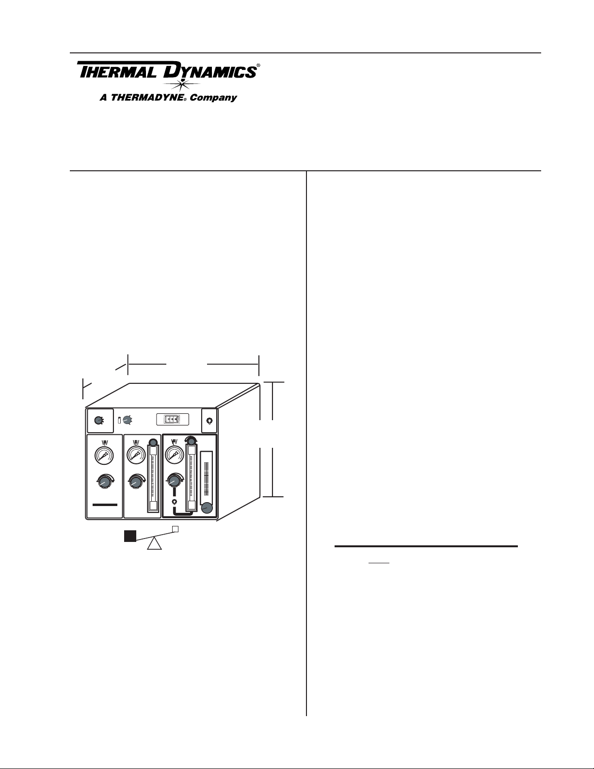
Specifications
Thermal Dynamics
Automated
Plasma Cutting System
9
GAS
16.25"
413 mm
AMPS
SHIELD
9
PRESSURE
FLOW
ENABLE
DISABLE
PLASMA
POWER SUPPLY
H
2
O
MIST
14.25"
362 mm
11"
279 mm
RUN
SET PREFLOW
SET PLASMA
& SHIELD
TEST
MODE
PREFLOW
GCM
2000
O2 - AIR
2
H35 - N
AIR - AIR
2
- H2O
N
GAS
PLASMA
Installation
Select a clean, dry location with good ventilation and
adequate working space around all components.
All gas inputs and two control cables attach to the rear
panel. A fiber-optic control cable passes through the
rear panel and connects to a printed circuit board inside the module. There must be adequate space behind the module for these hose and cable connections
without crimping.
The Gas Control Module must be installed in a suitable
location where it is easily accessible to the system operator. The unit must be mounted to a flat horizontal
surface. If the module is mounted to a gantry or any
other support subject to vibration or motion, the installer must fasten the module to the support securely.
The module should be located as far away as possible
from the Arc Starter due to electromagnetic interference. It is acceptable to locate the control cable in the
same track as the cables from the Arc Starter.
The module includes feet which lift the bottom panel
off the mounting surface. There are ventilation holes
on the bottom panel; the space between the bottom
panel and the mounting surface must remain open for
ventilating air to enter the module. Louvers on the back
panel of the module must also remain unblocked, for
the free passage of ventilating air.
NOTE
40 lb / 18 kg
Art # A-07282
The unit must be mounted so that the Flowmeters
are plumb. If the Flowmeters are not plumb,
incorrect flow indications may occur.
Scope of Instructions
These instructions cover installation of the gas control
module only. Operational instructions are provided in
the Auto-Cut® 20O2 and Auto-Cut® 30O2 power supply manuals.
© 2006, Thermadyne Corp.
March 6, 2006 1 Manual 0-4738 Rev. AA
Page 2
Preparation
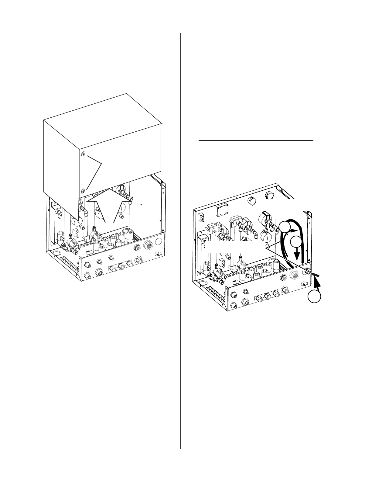
Fiber Optic Cable Installation
1. Remove the screws securing the cover panel to
the Module.
2. Remove the Cover from the Module.
Gas Control Module Cover
Do not remove
1. Remove the securing nut from the through-hole
protector supplied on the cable. Pass the cable
and the through-hole protector into the hole in
the connection panel on the back of the module. Fasten the through-hole protector in place
with the securing nut. Do not tighten the protector.
2. Pass the fiber-optic connector through the hole
in the connection panel. Pass enough of the
cable into the Module to let the cable loop upward as shown.
CAUTION
Avoid kinking, twisting, or bunching the fiberoptic cable. The cable can be damaged by being
forced into tight-radius turns.
Circuit Board
2
M
COM
J56
J57
POWER
LOW
F
E
R
P
A
M
S
LA
P
LD
IE
H
S
2O
H
IELD
H
S
AIR
2O
H
INPUTS
N
2
2
O
Art # A-07287
SUPPLY
TVA
H35
Fiber Optic Cable
PREFLOW
OUT
PLASMA
SHIELD
OUT
OUT
AIR N
O
2
H
INPUTS
2
O
2
3
M
M
O
C
J56
J57
POWER
SUPPLY
TVA
H35
1
Art # A-07285
3. Insert the fiber-optic cable connector into the
receptacle on the vertically-mounted circuit
board as shown.
March 6, 2006 2 Manual 0-4738 Rev. AA
Page 3

Circuit Board
Fiber Optic Cable
Art # A-07286
4. Tighten the through-hole protector for the fiberoptic cable.
5. Reinstall the cover panel.
March 6, 2006 3 Manual 0-4738 Rev. AA
Page 4

Supply, Control, and Output Connections
1 Position the module on a flat, horizontal sur-
face.
2. Ensure that the flowmeters are plumb.
3. Fasten the module to the mounting surface.
4. Connect inputs and outputs as shown.
NOTE
Water shield is not used in all applications.
5. Make all other connections as required to the
rear of the module. The connections and cables
are labeled or keyed. Gases must be connected
to the appropriate ports. Air must be connected
when cutting with O2 (oxygen) plasma.
6. The module must be grounded; the grounding
terminal is marked . Use #10 AWG (or thicker)
wire for grounding. Keep the ground wire as
short as possible.
NOTE
Every effort has been made to provide complete and accurate information in this
manual. However, the publisher does not
and hereby disclaims any liability to any
party for any loss or damage caused by errors or omissions in this manual, whether
such errors arise from negligence, accident,
or any other cause.
SHIELD PLASMA
H O
2
SHIELD
To Torch Valve Assembly
H O
2
PREFLOW
To Torch Valve Assembly
J57
When Cutting With O2 Plasma
Air MUST BE Connected
AIR
INPUTS
N2
O2
H35
Gas & Water Inputs (Check Valves)
TVA
To Power Supply
J56
POWER
SUPPLY
Ground Stud
COMM
Gas Control Module
Rear Panel
J56
Connection Panel
SHIELD PLASMA
H O
2
SHIELD
H O
2
PREFLOW
When Cutting With O2 Plasma
Air MUST BE Connected
INPUTS
AIR
N2
J57
TVA
H35
O2
COMM
POWER
SUPPLY
Art # A-07283
March 6, 2006 4 Manual 0-4738 Rev. AA
 Loading...