

Page 1
External
Original Publication Date: 2006 Manual no.: 0-4737
Revision Date: 2014 Revision: AD
Command & Control Module,
No. 9-9417 / 9-9418
for Automated Plasma Cutting
Power Supplies
Installation Instructions
General Information
These instructions cover the CCM (Command & Control
Module) for Thermal Dynamics Automated Plasma Cutting Power Supplies. Do not install this module on any
other equipment.
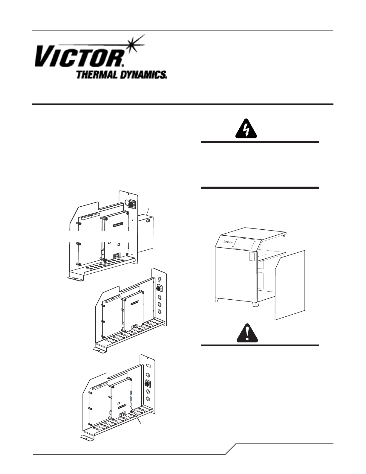
There are two types of module. One includes an external
strain relief cover assembly protruding from the back
panel. The other has a flat back panel. Refer to the illustration to confirm that the module is correct for the power
supply being serviced.
CCM Type 1
NO LONGER AVAILABLE
Connection
Cover
Procedure
WARNING
Disconnect primary power at the source and
bleed down the system before installing, inspecting, or repairing this equipment.
Only a qualified technician should install or
service this equipment.
1. Remove the power supply right side panel. Set the
panel aside carefully. A ground wire connects to the
inside of the side panel. Disconnect this wire if necessary to provide more room to work.
CCM Type 2
(Cat. No. 9-9418)
There is one section in these instructions for
each type of module. Be sure to follow the
CCM Type 3
(Cat. No. 9-9417)
Art # A-06871_AB
Manual 0-4737 1
USB
correct section for the type of module being
replaced.
Art # A-07333
CAUTION
Page 2
Removal and Replacement, Type 1 Module
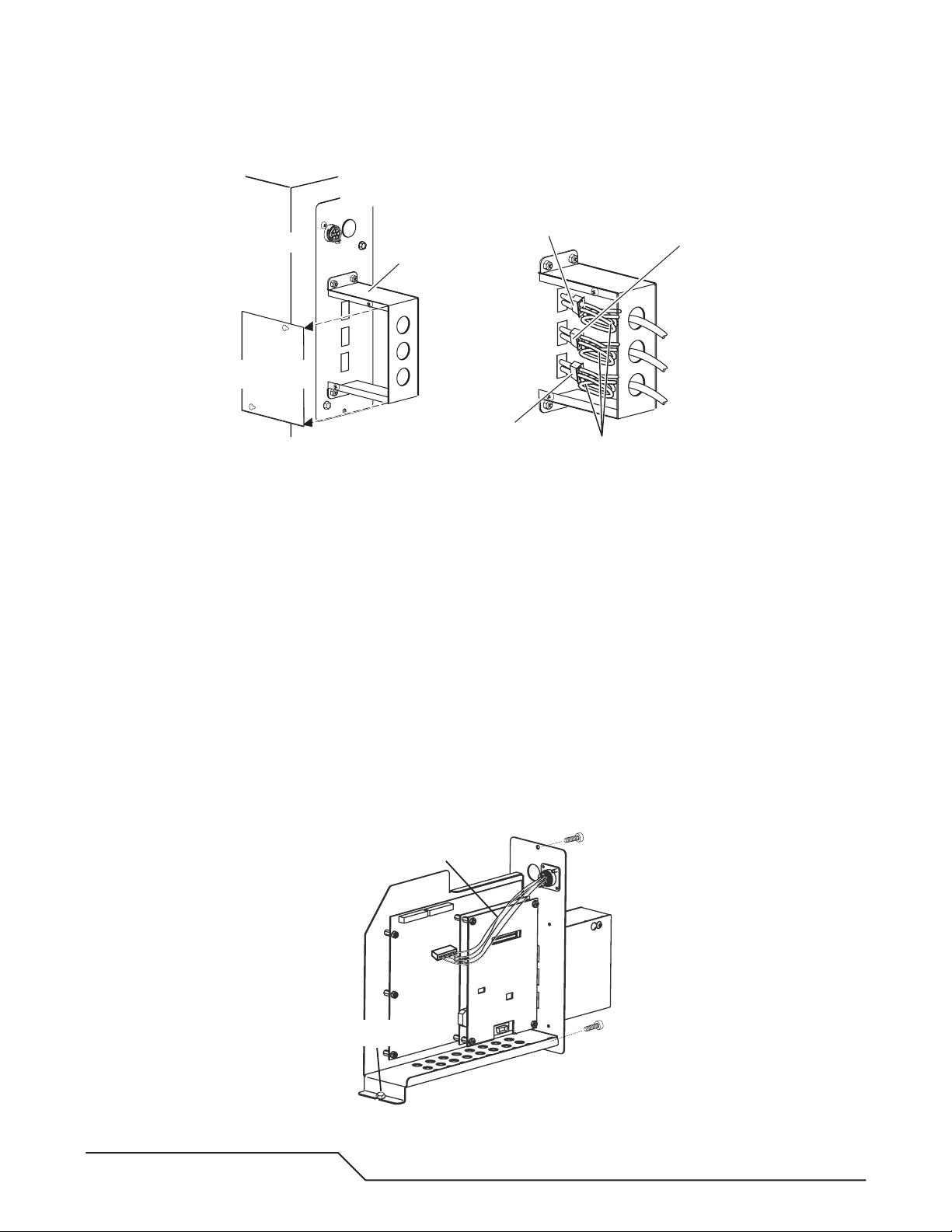
A. Disconnect External Connections (Type 1 Module)
Power Supply
Right Side Panel
Connection Cover
Side Panel
1
Power Supply
Rear Panel
Connection Cover
To Gas Control Module
To Slave Power Supply
(if installed)
2
Cable Loops
To Remote HMI
(if installed)
Art # A-06873
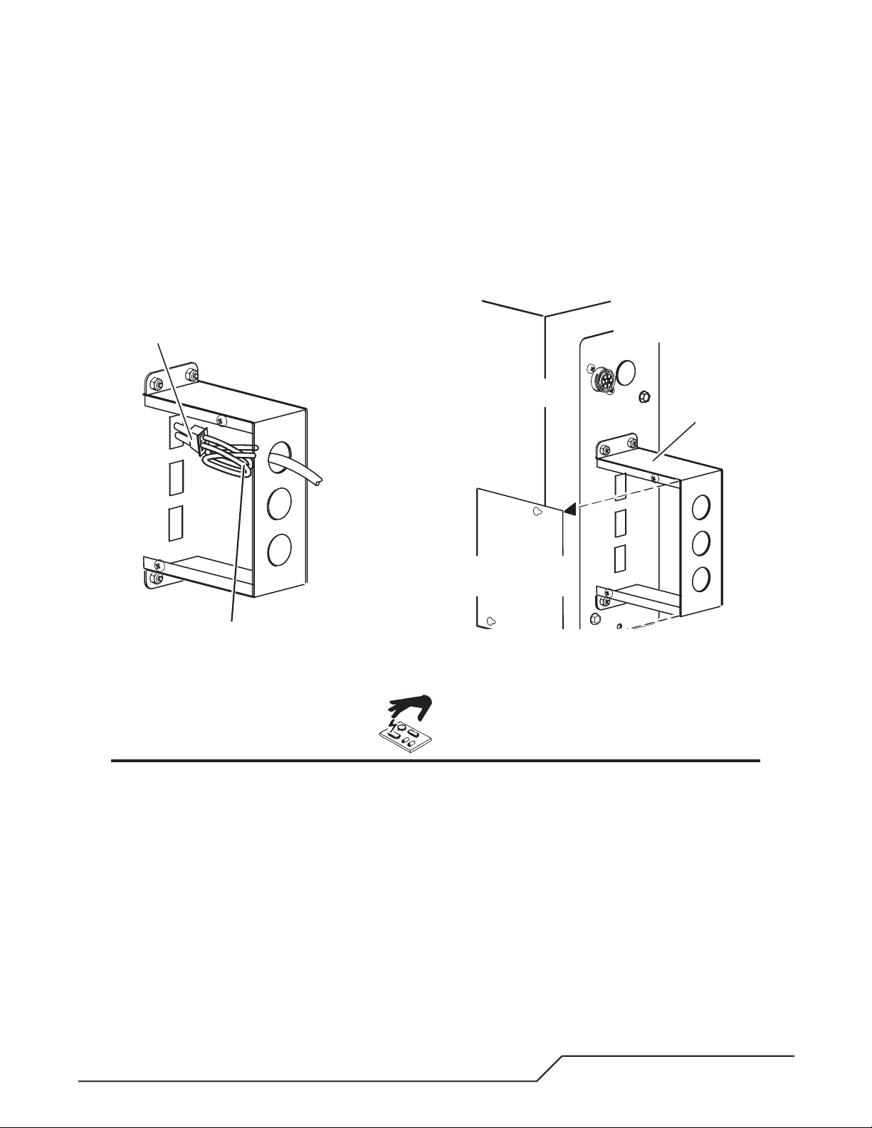
1. Remove the side panel from the connection cover.
2. Carefully label and disconnect all external cables connected to the module.
3. Remove and keep the strain relief nut(s) holding the strain relief(s) to the connection cover. Carefully pull the
cable(s) and strain relief(s) out of the connection cover. Leave the strain relief(s) on the cable(s).
B. Disconnect Internal Wire Harnesses
1. A wire harness connects the module rear panel to the larger PC Board in the module. Leave this harness in
place. Carefully label and disconnect all other internal wire harnesses connected to the module. Take care to
label the harnesses connected to terminals J1 and J7 properly to ensure connections to the correct terminals
on the replacement assembly. The harness connectors include latches that must be compressed to release
them from the PC Board receptacles.
2. Loosen, but do not remove, the internal bolt fastening the module to the power supply inner horizontal panel.
3. Remove the hardware holding the module rear panel to the power supply rear panel. Save the hardware for
re-use.
4. Carefully slide the module out of the power supply. Keep the module nearby to serve as a reference for setting
the switches on the replacement module.
Leave this harness in place
Internal Bolt
Art # A-06874
2 Manual 0-4737
Page 3
C. Install Replacement Module
1
2
1. Lift the internal wire harnesses to let the module slide under them. Carefully slide the replacement module
into the power supply. Ensure that the internal bolt engages the slot in the inner end of the module’s bottom
plate. Fasten the module back panel in place with the hardware removed previously. Tighten all hardware
securely. Do not overtighten.
2. Carefully connect all internal wire harnesses to the module according to the labels applied to the harnesses
previously.
3. Reconnect the external harness connections to the module. Re-install the connections cover side panel.
To Gas Control Module
Power Supply
Right Side Panel
Connection Cover
Side Panel
Power Supply
Rear Panel
Connection Cover
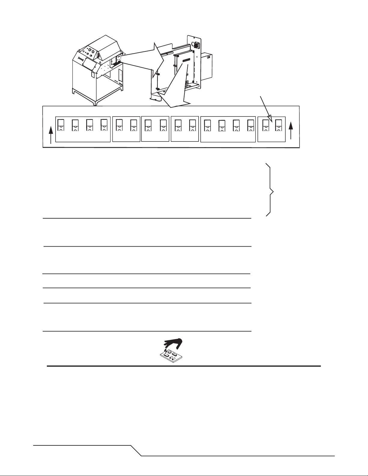
D. Set Command-Control Module Switches
Set switches on the module per the illustrations, or match the switch settings to those on the original module.
CAUTION
Printed circuit boards in the Command - Control Module are static - sensitive. Discharge any built-up
static charges in your body or surroundings before touching the printed circuit boards.
Manual 0-4737 3
Page 4
Future Use
2
SW1
3
O
N
1
SW-1-1: Auto Pilot Restart. 1 = ON = Auto Pilot Function enabled.
1 = OFF = Auto Pilot Function disabled (Factory default setting).
SW-1-2: Pilot Delay 2 = OFF, 3 = OFF, 4 = OFF: 0 Seconds (Factory default setting).
SW-1-3: Pilot Delay 2 = ON, 3 = OFF, 4 = OFF: 0.1 Seconds
SW-1-4: Pilot Delay 2 = OFF, 3 = ON, 4 = OFF: 0.2 Seconds
2 = ON, 3 = ON, 4 = OFF: 0.4 Seconds
2 = OFF, 3 = OFF, 4 = ON: 0.8 Seconds
2 = ON, 3 = OFF, 4 = ON: 1.0 Seconds
2 = OFF, 3 = ON, 4 = ON: 1.5 Seconds
2 = ON, 3 = ON, 4 = ON: 2.0 Seconds
SW-3: Gas Preflow Time 1 = OFF, 2 = OFF: 2 Seconds (Factory default setting).
1 = ON, 2 = OFF: 4 Seconds
1 = OFF, 2 = ON: 6 Seconds
1 = ON, 2 = ON: 8 Seconds
SW-4: Postflow Time 1 = OFF, 2 = OFF: 10 Seconds (Factory default setting).
1 = ON, 2 = OFF: 20 Seconds
1 = OFF, 2 = ON: 5 Seconds
1 = ON, 2 = ON: 0 Seconds (Disabled)
SW-5-1: Tip Saver 1 = OFF = Disabled (Factory default setting).
1 = ON = Enabled
SW-5-2: Off Plate 2 = OFF = Disabled (Factory default setting).
2 = ON = Enabled
SW 8-1: Pilot Time 1 = OFF = Short (85 ms.) (Factory default setting).
1 = ON = Long (3 s.)
SW 8-2: Remote Current 1 = ON (Remote Analog Current Control)
SW8-3, SW 8-4: Reserved for Factory use.
SW3 SW4
1
4
SW5 SW8
2
1
1
2
2
1
2
4
3
O
N
1
2
Active only when
SW-1-1 is set to ON.
Art # A-04825
CAUTION
Printed circuit boards in the Command - Control Module are static - sensitive. Discharge any built-up
static charges in your body or surroundings before touching the printed circuit boards.
4 Manual 0-4737
Page 5

SW6: OK-to-Move: Contact closure, 120VAC @ 1A (Factory default setting) or
DC Volts (16-18vdc@ up to 100 ma.)
SW11: Analog Current Control. B = from Gas Control (Factory default setting) or A = from CNC.
Position A requires that SW-8-2 be ON.
SW12-1/2/3/4: Divided Arc signal
All = OFF = 50:1 (Factory default setting)
1 = ON = 16.6:1
2 = ON = 30:1
3 = ON = 40:1
4 = Not used.
Art # A-07673
Only 1 on at a time.
SW11
SW13
SW6
SW12
SW13: TVA and XTL Switch positions
SW13
1
2
1
2
TVA XTL TVA
NOTE
Standoff Control SC-11 requires Switch 12-1 set to ON.
Reinstall the power supply side panel. Reconnect input power. Test the system for proper operation.
Manual 0-4737 5
Page 6

Removal and Replacement, Type 2 Module
A. Disconnect and Remove Type 2 Module
1. A wire harness connects the module rear panel to the larger PC Board in the module. Leave this harness in
place. Carefully label and disconnect all other internal wire harnesses connected to the module. Take care to
label the harnesses connected to terminals J1 and J7 properly.
2. Carefully label and disconnect all external wire harnesses connected to the module.
Cable Receptacles
Use top ONLY
Profile Detail, Fiber Optic Cable Installation
To Gas Control Module
Art # A-06793_AB
3. Loosen, but do not remove, the internal bolt fastening the module to the power supply inner horizontal panel.
4. Remove the hardware holding the module rear panel to the power supply rear panel. Save the hardware for
re-use.
5. Carefully slide the module out of the power supply. Keep the module nearby to serve as a reference for setting
the switches on the replacement module.
B. Install and Connect Type 2 Module
1. Lift the internal wire harnesses to let the module slide under them. Carefully slide the replacement module
into the power supply. Ensure that the internal bolt engages the slot in the inner end of the module’s bottom
plate. Fasten the module back panel in place with the hardware removed previously. Tighten all hardware
securely. Do not overtighten.
2. Carefully connect all internal wire harnesses to the module according to the labels applied to the harnesses
previously.
3. Reconnect the external harness connections to the module.
6 Manual 0-4737
Page 7

Cable Receptacles
Use top ONLY
To Gas Control Module
Profile Detail, Fiber Optic Cable Installation
Art # A-06793_AB
C. Set Switches for Type 2 Command-Control Module
Set switches on the module per the illustrations, or match the switch settings to those on the original module.
CAUTION
Printed circuit boards in the Command - Control Module are static - sensitive. Discharge any built-up
static charges in your body or surroundings before touching the printed circuit boards.
Manual 0-4737 7
Page 8

.
Future Use
O
N
SW1
1
3
2
SW3 SW4
1
4
Switches shown in OFF position
2
1
SW5 SW8
1
2
2
4
1
3
2
1
SW-1-1: Auto Pilot Restart. 1 = ON = Auto Pilot Function enabled.
1 = OFF = Auto Pilot Function disabled (Factory default setting).
SW-1-2: Pilot Delay 2 = OFF, 3 = OFF, 4 = OFF: 0 Seconds (Factory default setting).
SW-1-3: Pilot Delay 2 = ON, 3 = OFF, 4 = OFF: 0.1 Seconds
SW-1-4: Pilot Delay 2 = OFF, 3 = ON, 4 = OFF: 0.2 Seconds
2 = ON, 3 = ON, 4 = OFF: 0.4 Seconds
2 = OFF, 3 = OFF, 4 = ON: 0.8 Seconds
2 = ON, 3 = OFF, 4 = ON: 1.0 Seconds
2 = OFF, 3 = ON, 4 = ON: 1.5 Seconds
2 = ON, 3 = ON, 4 = ON: 2.0 Seconds
SW-3: Gas Preflow Time 1 = Off, 2 = OFF: 2 seconds
1 = ON, 2 = OFF: 4 seconds
1 = OFF, 2 = ON: 6 seconds
1 = ON, 2 = ON: 8 seconds
SW-4: Postflow Time 1 = OFF, 2 = OFF: 10 Seconds (Factory default setting).
1 = ON, 2 = OFF: 20 Seconds
1 = OFF, 2 = ON: 5 Seconds
1 = ON, 2 = ON: 0 Seconds
SW-5-1: Tip Saver Reserved for Factory use.
SW-5-2: Off Plate Reserved for Factory use.
SW 8-1: Pilot Time 1 = OFF = Short (85 ms.) (Factory default setting).
1 = ON = Long (3 s.)
SW 8-2: Remote Current 1 = OFF = Disabled (Factory default setting).
1 = ON = (Remote Analog Current Control)
*SW 8-3: Auto Tr ansfer Retry1 = OFF = Enabled Up to 3 tries (Factory default setting).
1 = ON = Disabled
SW 8-4: Reserved for Factory use.
O
N
2
Active only when
SW-1-1 is set to ON
* SW 8-3 is reserved for
Factory use prior to
Art # A-06869_AB
Firmware V3.5
CAUTION
Printed circuit boards in the Command - Control Module are static - sensitive. Discharge any built-up
static charges in your body or surroundings before touching the printed circuit boards.
NOTE
Standoff Control SC-11 requires Switch 12-1 set to ON.
8 Manual 0-4737
Page 9

SW-6: OK-to-Move: Contact closure, 120VAC @ 1A (Factory default setting) or
DC Volts (16-18vdc@ up to 100 ma.)
SW-11: Analog Current Control. B = from Gas Control (Factory default setting) or A = from CNC.
Position A requires that SW-8-2 be ON.
SW-12-1/2/3/4: Divided Arc signal
All = OFF = 50:1 (Factory default setting)
1 = ON = 16.6:1
2 = ON = 30:1
3 = ON = 40:1
4 = Not used.
Art # A-07674
Only 1 on at a time.
SW11
SW13
SW6
SW12
No external
connection cover
SW13: TVA and XTL Switch positions
SW13
1
2
1
2
TVA XTL TVA
Manual 0-4737 9
Page 10

D. CCM CPU PC Board Layout
Note: Switch Settings May Vary.
O
N
1
TP1
TP3
TP6
PRE
FLOW
SW1
SW3
1
1
J2
J3
Art # A-06906
3
2
+
H5
1
29
+
U22
U26
4
R1
C1
R7
H2
R10
C2
21
R17
C4
J2
3029
C7
C8
R33
R34
R38
R41
GP1
2
J3
30
C31
C34
U18
GP2
R74
R91
H1
TP8
D11
1
1
TEMP
SENSE
R51
R61
R78
R88
C47
C26
R2
R18
C5
TP3
+5.0V
R32
U10
R52
U6
TP6
R62
C48
R30
R53
D12
R79
C53
TP1
GND
1
C58
1
R3
R19
R31
R35
J4
C21
TPAD1
R63
R80
R25
C9
1
POST
FLOW FUNC
SW4
1
R20
R26
R27
R29
D3
D7
C22
R55
C28
R64
R82
R85
R89
RC
J5
1
R5
R6
R8
1
C3
R11
AUTO PILOT
1
1
2
D2
D4
D5
D8
D10
C12
C19
C18
R58
160
1
U20
R83
R86
R90
C57
SW1
3
120
C54
R12
C35
R76
1
U23
R94
1
4
1
U14
TP8
CLKO
U27
R54
U31
2
R4
U7
R28
C6
D1
D6
D9
C25
NC
R60
C32
R75
R81
1
2
Switches
R13
R14
R21
R22
POST
PRE
FLOW
FLOW FUNC
SW3
SW4
1
1
2
44
1
R44
C14
C13
C37
L2
C42
+
C43
L5
C49
+
C55
J1
1
6
J1
SW5
1
U5
R15
R16
R24
R23
SW5
1
1
2
U4
C16
C15
D13
U21
L3
+
5
9
SYS
CONTAUTO PILOT
SW8
1
2
R9
1
1
2
23
R39
22
R45
L1
80
40
R70
1
R84
C44
C50
1
2
CPU/COMMUNICATIONS
SYS
OK TO
CONT
MOVE/D
SW8
SW9
C 2004 TDC
19X2169 REV
1
1
R42
C20
D14
R36
R49
2
R71
R59
R67
+
3
C23
C36
R40
C45
C51
4
TP4
/WR
TP7
/RD
Y1
R65
+3.3VA
L4
TP2
AGND
C46
C56
C59
1
2
1
C10
R46
+
C17
R47
R48
R57
R56
C30
C29
R66
R68
R69
TP5
R72
C38
C41
R87
U28
C52
U32
+
OK TO
MOVE/D
SW9
1
C40
R93
-15V
AC
R37
H4
H3
U9
U12
C24
U15
U17
U25
U29
+3.3V
TP11TP10TP9
1
H6
3
4
U8
C11
R43
U11
1
U13
1
R50
C27
U16
1
C33
U19
1
R73
C39
R77
1
U24
1
R92
+15V
DACDAC
U30
1
L6
D15
TP9 TP10 TP11
O
N
2
TP4
TP7
TP5
TP2
10 Manual 0-4737
Page 11

E. CCM PC Board Layout
SW11
SW6
J36
SW12
J1
H2
1
DC VOLTS
SW6
R227
R228
OK TO MOVE SELECT
CONTACTS
Q2
D14
R226
R55
R73
H9
R79
R82
R88
R93
R100
R109
R114
C64
R129
R128
R131
ALL SW OFF FOR 50:1 (DEFAULT)
SW12-1 ON FOR 16.7:1 (SC-11)
SW12-2 ON FOR 30:1
SW12-3 ON FOR 40:1
SW12-4 SPARE
D31
4
3
2
SW12
1
C76
1
ISOLATED
TP6
-15V
+15V
H1
+18VGND
TP10
R5
R9
1
C6
C8
R25
AUTO PILOT
U6
R49
U10
D10
C19
U12
C18
R119
R83
R86
C87
R145
J7
J7
1
L2
1
R225
C1
R6
R8
C3
C3
R12
R11
R12
R27
R26
SW1
1
1
C24
C23
C25
1
3
2
4
D2
D4
R51
R50
R68
D5
D8
R44
1
R67
R66
C14
C13
C12
1
120
R107
C54
R58
C53
R112
160
1
U14
C35
R123
1
R124
U20
TP8
CLKO
R76
+
1
U23
D33
D34
D35
R90
U22
+
C88
U27
1
R94
C54
C57
R13
R28
PRE
FLOW
SW3
44
R21
1
1
1
C4
R13
R14
R29
C12
2
R52
R69
C37
C42
R98
C37
D61
L2
C42
C43
+
L5
6
U1
R5
R10
C7
R15
R16
C9
R22
R23
POST
FLOW FUNC
SW4
R32
1
C26
1
C27
R54
R53
R71
R70
R78
C15
C43
+
U14
C60
C62
C79
+
C49
C89
C55
R142
J1
R150
1
R33
2
U4
U17
C91
R146
U5
1
L3
1
U4
R87
R120
C2
R223
R9
R16
R24
SW5
C13
1
1
2
U7
23
C16
L1
1
40
D13
R127
D60
U21
1
C80
C83
+
R143
5
R147
9
TP9
CC POT
CPU/COMMUNICATIONS
R6
U2
U3
C5
D5
C10
R17
SYS
OK TO
CONT
MOVE/D
SW8
SW9
K5-E-STOP
1
R34
R35
C14
R36
1
1
3
2
4
R42
R37
TP4
/WR
R36
C30
D18
R40
TP7
R39
/RD
R42
22
Y1
+
R45
C39
C20
C23
80
C44
R49
R99
R56
R108
C55
R59
C29
R113
C63
R65
R121
R67
+
1
R125
C36
C67
R70
+3.3VA
+
R71
D14
L4
C75
TP2
AGND
R84
+
C45
+
C46
C44
C90
+
C51
C50
D36
R144
C56
U24
1
R151
C59
B
D1
SW11
A
GAS ON
1
C 2004 TDC
19X2169 REV
D13
1
2
U8
1
R38
R57
C11
C10
R46
C TDC 2005
19X2174
C17
REV
R47
R48
R57
C30
R66
R68
R69
TP5
R72
C38
R77
C41
U24
R87
U28
C52
U32
D37
+
D2
E-STOP_PS
R39
AD+
C27
C33
C39
R92
L6
1
K7-GAS ON
R43
U11
1
U13
1
R50
U16
1
U19
1
R73
1
1
+15V
DACDAC
U30
1
D15
J8
J8
H3
H3
AC
H8
H6
R37
U9
U12
C24
U15
U17
C40
U25
U29
R93
-15V
+3.3V
TP11TP10TP9
H4
H4
Art # A-07395
TB1
TB1
J1
K4-OK
D7
K3-E-STOP CNC
R30
1
Q3
K1-PSR
K2-START
D17
R56
C33
D20
D21
C40
CNC_E-STOP
D22
D23
C45
CNC_START
D25
D26
C56
HOLD_START
D28
D27
CNC PREFLOW
C66
R126
C65
U18
1
C72
+
R134
R157
R136
R156
+
R138
R155
C85
R158
C84
C93
TP7
+
C92
TP8
R149
C95
TB2
11
TB2
R1
OK CNC
R31
D9
R40
D15
U11
1
D24
C46
U15
1
TP4
+5V
J35
2
1
C68
1
U19
C73
U20
U23
1
+
C94
D38
+
R148
1
R7
R14
D3
R15
D4
D6
C15
C28
D16
R43
C31
PSR
R59
R58
R74
R72
C34
R80
C35
R83
R95
U13
R94
R101
R110
C57
C61
C69
R132
R135
C74
C78
C77
1
U21
T1
D39
J35
J9 J5
J4
J4
J9
K6
D10
+
D11
+
C29
L1
1
D19
U8
C32
1
R75
C41
U9
R84
+
R89
R96
R102
R103
1
D29
C58
1
D30
+
R130
TP1
GND
C70
TP5
-15V
TP3
+15V
R8
D8
D12
C36
33
R105
R104
R111
U16
TP2
+29-41 VDC
SW13
TP11
ARC V-
1
34
CUT
DEMAND
+
26
25
SW13
1
1
2
2
J2
J5
1 1
H6
C2
+
J2
R154
R152
29
C7
H7
J36
H5
H10
1
PILOT
DEMAND
TP14
J3
TP13
R106
29
C59
29
C31
+
H11
U22
R133
U26
H5
J6
J6
PILOT V
R224
R2
R1
R3
C1
R7
H2
R11
R10
2
1
21
R17
C4
J2
3029
30
C8
R33
R34
R38
R41
GP1
2
1
R77
2
R81
R85
J3
R90
C47
D11
30
30
R115
C34
U18
GP2
1
R74
C71
Q1
1
R91
H1
TP12
R2
1
R19
C5
R18
TP3
+5.0V
C11
C16
R32
R41
R60
TEMP
SENSE
U10
R76
R91
R52
R97
R51
C48
R61
R116
R78
R88
C86
C47
R141
D40
C26
R4
R4
R3
U6
U7
R18
R20
R19
R21
R20
R23
R24
R22
R26
R25
TP1
R27
GND
R28
1
R29
U5
1
C17
C18
R30
C22
C6
C20
R31
C21
D1
R47
D3
R35
R45
C19
R44
R64
R48
R46
D6
TP6
R62
C9
D7
R65
R63
R61
1
D9
R86
J4
C38
R53
C21
C22
R92
R55
R54
C25
C50
TPAD1
C49
D12
C51
NC
C52
C28
R62
R63
R60
R64
C32
R117
R118
R122
R75
R82
R81
R80
R79
C82
+
D32
R85
C81
R89
RC
R139
C48
R140
J5
C53
U31
C58
1
NOTE
Wire harnesses connected to Terminals J1 and J7 must not be reversed.
Manual 0-4737 11
Page 12

NOTE
Every effort has been made to provide complete and accurate information in this manual. However,
the publisher does not assume and hereby disclaims any liability to any party for any loss or damage
caused by errors or omissions in this Manual, whether such errors result from negligence, accident, or
any other cause.
INNOVATION TO SHAPE THE WORLD™
INNOVATION TO SHAPE THE WORLD™
U.S. Customer Care: 800-426-1888 Canada Customer Care: 905-827-4515 International Customer Care: 940-381-1212
U.S. Customer Care: 800-426-1888 Canada Customer Care: 905-827-4515 International Customer Care: 940-381-1212
© 2001 Victor Technologies International, Inc. www.victortechnologies.com Printed in USA
© 2001 Victor Technologies International, Inc. www.victortechnologies.com Printed in USA
 Loading...