

Page 1
Manual 0-4763
82 Benning Street, West Lebanon, NH 03784 USA
(603) 298-5711 • www.thermal-dynamics.com
Application
This product is for use only with Thermal Dynamics Gas
Control Module GCM-2010. Do not use this product with
any other equipment.
Unpacking
The product is packaged and protected to prevent damage
during shipping. Inspect for possible shipping damage.
If damage is evident, contact your distributor and/or shipping company before proceeding with installation.
Contents
• PC Board Assembly, including:
Display PC Board and
Interface PC Board with connecting ribbon cable
• 8 Plastic Standoffs
• 4 Plastic Nuts
• Static handling items and instructions
• PC Board Installation Instructions
GCM-2010
Display and Interface PCB Kit
Catalog# 9-9408
Installation Instructions
Procedure
WARNING
Disconnect primary input power at the source and
bleed down the system before starting this procedure.
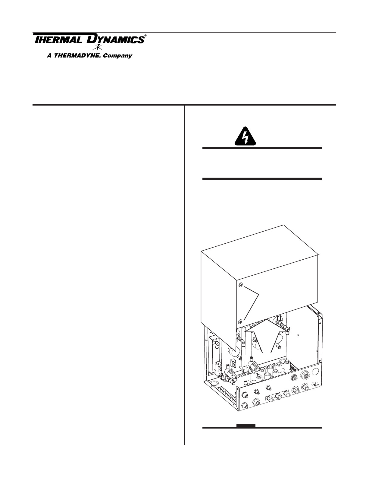
1. Remove the cover from the Gas Control Module. A
ground wire connects the cover to the module. Do
not disconnect this wire.
Gas Control Module Cover
Do not remove
M
M
O
C
J56
H
S
H
SHIELD
J57
W
FLO
PRE
A
M
S
A
L
P
D
L
IE
O
2
N
AIR
O
2
H
U
INP
2
TS
2
O
H
Art # A-07062
ER
POW
PPLY
U
S
F5
A
TV
35
CAUTION
Follow the static handling directions provided separately.
© 2005 by Thermal Dynamics Corp., Printed in USA
April 6, 2006 1 Manual 0-4763 Rev. AA
Page 2

Plastic Nuts
Ribbon Cable to Main PC Board
Control Module, Front Panel
Interface PC Board
Interconnecting Ribbon Cable
(to Display PC Board)
2. Disconnect the ribbon cable connected to the top
edge of the interface PC Board.
3. Remove the four plastic nuts holding the interface
PC Board to the Display PC Board. Gently pull the
interface PC Board off the standoffs.
CAUTION
Do not pull or twist the interconnecting ribbon cable.
4. Remove the four plastic standoffs holding the Display PC Board to the module front panel. Pull the
assembly (2 PC Boards, with interconnecting ribbon cable) off the plastic standoffs. Do not pull or
twist the interconnecting cable. Set the assembly
aside carefully.
NOTE
Leave the clear plastic panel in place on the module
front panel.
5. Position the replacement Display PC Board on the
standoffs mounted to the module front panel, in
the same orientation as the original Display PC
Board. The interface PC Board should hang freely
from the display board, attached by the interconnecting ribbon cable. Do not twist or pull the interconnecting ribbon cable. Fasten the display
board in place with 4 plastic standoffs. Tighten
the standoffs snugly by hand. Do not overtighten.
Art # A-07373
6. Position the replacement interface PC Board on the
standoffs, in the same orientation as the original
interface PC Board. Do not twist or pull the interconnecting ribbon cable. Fasten the interface board
in place with 4 plastic nuts. Tighten the standoffs
snugly by hand. Do not overtighten.
7. Reconnect the ribbon cable from the main PC Board
to the interface PC Board. Check for a secure connection.
8. Reinstall the control Module Cover. Be sure the
ground wire is not crimped between the cover and
the module.
9. Reconnect input power to the system. Test the unit
for proper operation.
NOTE
Every effort has been made to provide complete
and accurate information in this manual.
However, the publisher does not assume and
hereby disclaims any liability to any party for
any loss or damage caused by errors or omissions in this Manual, whether such errors result from negligence, accident, or any other
cause.
April 6, 2006 2 Manual 0-4763 Rev. AA
 Loading...