

Page 1
Scope
This kit is for use only with the following Thermal Dynamics Plasma Cutting Systems:
Do not use this kit with any other equipment.
CutMaster 52,82,102,152
Manual 0-5121
Automation Interface Kit No. 9-8311
For CutMaster True Series
Installation Instructions
Installation Procedure
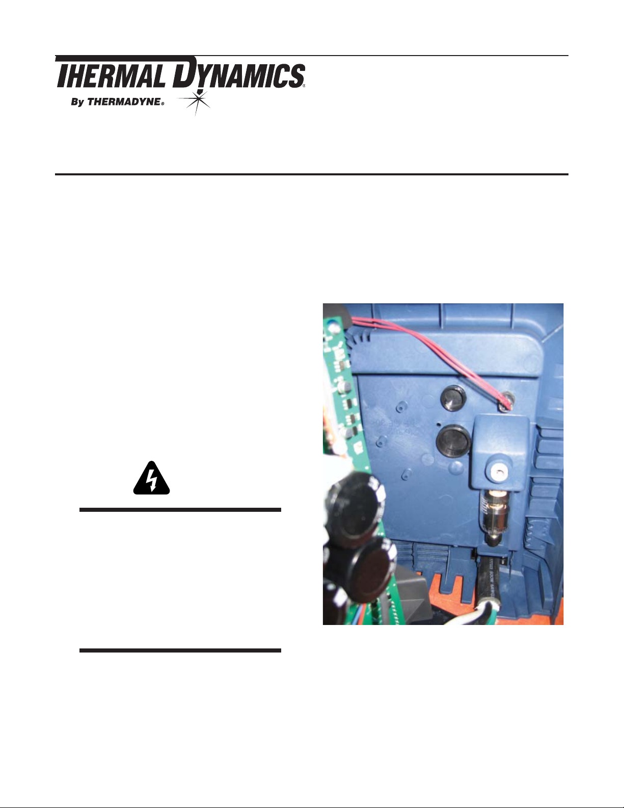
1. Remove the power supply cover.
2. Connect the supplied harness to the Automation
Interface Pcb by attaching the Fast-on terminal onto
the mating male terminal and the 8 socket receptacle
onto the P2 connector.
CutMaster 12mm,20mm,25mm,35mm, 40mm
CutMaster A40, A60,A80,A120
Supplied Parts
The kits include:
• Automation Interface Pcb 9-8388
• Wire Harness
• (2) #6-32x3/8 Pan Head Screws
• (2) M4x10mm Torx Head Screws
• Installation Instructions
Instructions
WARNINGS
Disconnect primary power at the source before
performing any inspection or repairs.
Only a qualifi ed technician should perform this
procedure.
3. Remove the lower hole plug from the rear panel.
Follow the electrostatic discharge instructions
included with the component to prevent damage
to the component.
© 2008 Thermadyne Corp.
October 7, 2010 1 Manual 0-5121 Rev. AA
Page 2
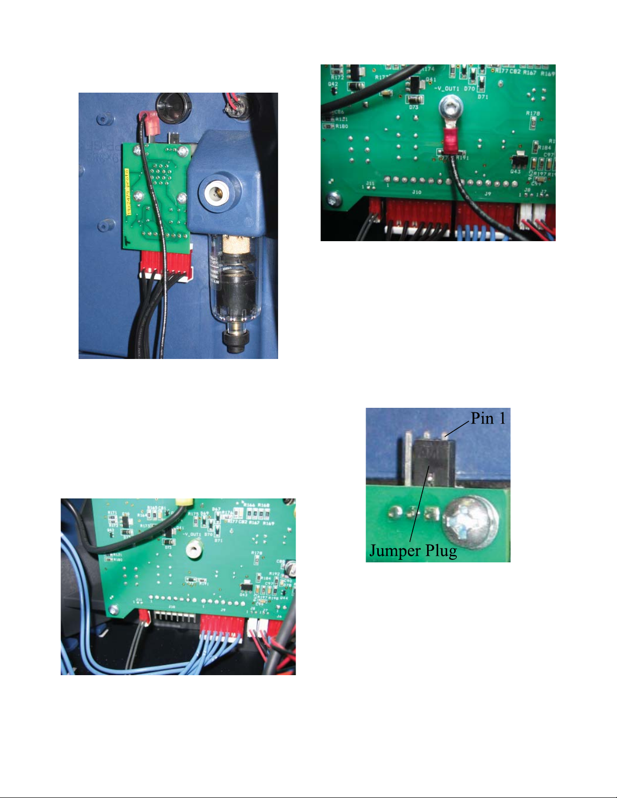
4. Using the two (2) #6-32x3/8 Pan Head Screws, mount
the pcb onto the rear panel, oriented as shown.
6. There are three options for Divided Arc Voltage signal
supplied from the pcb. This is selected by connecting
the black Jumper Plug on the P1 connector as follows:
Arc voltage / 16.67 Jumper not installed
4. Route the wire harness wires to avoid being damaged
and connect the wire harness wire with ring terminal
to the Main PCB1 terminal -Vout1 using a M4x10mm
Torx Head Screw.
5. Connect the 8 socket receptacle to the J10 connector
on Main PCB1.
Arc voltage / 30 Jumper Pins 1 & 2
Arc voltage / 50 Jumper Pins 2 & 3
October 7, 2010 2 Manual 0-5121 Rev. AA
Page 3

FULL FEATURED AUTOMATION INTERFACE PCB OPTION
To -V OUT 1
on PCB1
P10P10
1
2
3
4
5
6
7
8
**
123
J3J3
E1E1
J1J1
+12VDC
1
2
3
4
5
6
7
8
K1K1
PCB4
AUTOMATION
INTERFACE PCB
To configure DIVIDED ARC VOLTS signal output
No jumper installed for ARC VOLTS /16.67
Jumper pins 1 & 2 for ARC VOLTS / 50
Jumper pins 2 & 3 for ARC VOLTS / 16
J2J2
1
2
K1
3
4
5
6
7
8
9
10
11
12
13
14
/START / STOP
}
(-)
DIVIDED ARC VOLTS
}
*
(+)
(-)
ARC VOLTS
}
(W/ 100K IN SERIES (2))
(+)
OK-TO-MOVE
}
Art # A-09819
October 7, 2010 3 Manual 0-5121 Rev. AA
 Loading...