

Page 1
Manual 0-2834
RPT Adapter Kit
Catalog # 7-3450
Installation Instructions
General Information
This Replacement Torch Adapter Kit is to be used to connect the Thermal Dynamics Plasma RPT Series Cutting Torch to the
following equipment:
Thermal Dynamics EconoPak 100
Parts Supplied
The following parts are included in this kit:
• Control Connector Wires with Connectors (1 ea)
• Pilot Lead Adapter with Insulation Sleeving (1 ea)
Installation
Install the Adapter Kit per the following procedure:
1. Turn OFF the power supply.
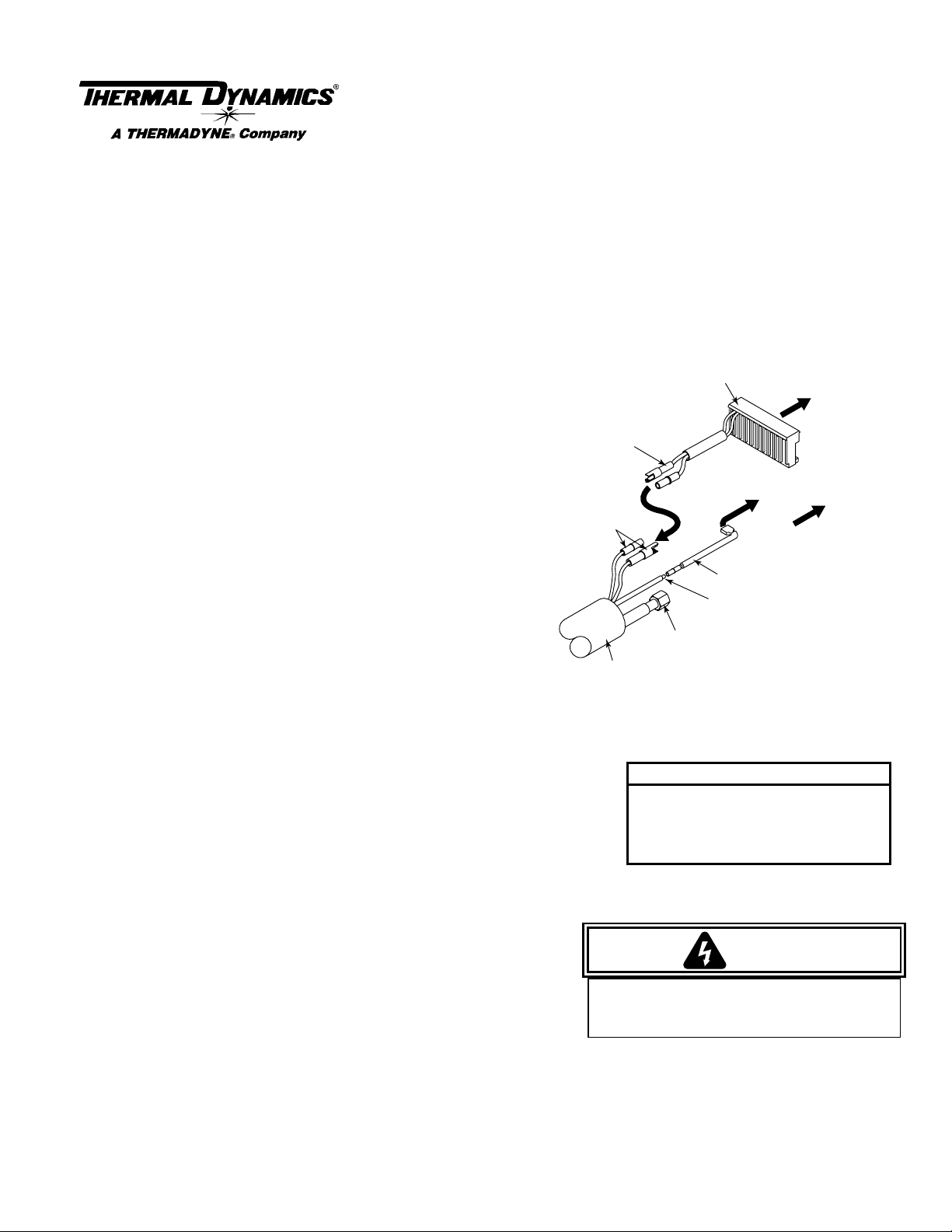
Control Connector
Wires with Connectors
Ten-Pin Connector
To Power Supply
Control Connector
2. Disconnect the main input power to the power supply.
3. Remove the existing torch from th e power supply, removing
Torch Control
Connectors
covers as required.
4. Connect the pilot wire (+) from the replacement torch to the
Power Supply per the following procedure:
a. Measure back 2 inches (50.8 mm) on the pilot lead
from the ring terminal and cut the pilot lead off at this
point.
b. Strip the pilot lead wire insulation 9/32 inch.
c. Using the proper wire crimping tool, crimp the Pilot
Negative/Plasma Lead
Torch Lead Assembly
Ring T erminal Removed
Lead Adapter onto the pilot lead at the butt splice.
d. Pull the Pilot Return Insulation Sleeving over the butt (in-line) splice.
e. Connect the end of the Pilot Return Adapter to the pilot terminal on the Power Supply.
5. Connect the Negative/Plasma Lead from the replacement torch to the Adapter
Fitting. Slide the protective boot over the lead connection.
6. Connect the Control Connector Wire (see NOTE) to the two mating connectors on
the replacement torch leads to the two mating connectors on the replacement torch
leads.
For Mechanized Systems refer to the
Torch Control Cable Wiring Diagram
in the Manual supplied with the RPT
Torch.
7. Connect the PCB Header (10-pin connector) of the Control Connector Wires to the Power Supply.
8. Reinstall any covers removed (see WARNING).
9. Install the proper torch consumables for the Power Supply amperage.
To Power Supply
Pilot Connector
Pilot Lead Adapter
Pilot Lead With
NOTE
WARNING
To Power Supply
(-) Fitting
A-02940
10. Reconnect main input power to the Power Supply and turn the unit ON.
Make sure that the Control Connector Wires DO
NOT contact the Negative/Plasma Lead Fitting
11. Set air pressure to 60 - 70 psi (4.1 - 4.8 bar).
after all leads are connected.
12. Test torch for proper operation.
NOTE
Every effort has been made to provide complete and accurate information in this manual. However, the publisher does not
assume and hereby disclaims any liability to any party for any loss or damage caused by errors or omissions in this manual,
whether such errors result from negligence, accident or any other cause.
© 2000 Thermal Dynamics Corp., Printed in USA
Installation Instructions 7/25/00
 Loading...