

Page 1

Manual 0-2832
82 Benning Street, West Lebanon, NH 03784 USA
(603) 298-5711 • www.thermal-dynamics.com
RPT Adapter Kit
Catalog # 7-3449
Installation Instructions
General Information
This Replacement T orch Adapter Kit is to be used to connect the Thermal Dynamics Plasma RPT Series Cutting T o rch
to the following equipment:
Thermal Dynamics EconoPak 50
Parts Supplied
The following parts are included in this kit:
• Control Connector W ir es with Connectors
• Pilot Return Adapter with Insulation Sleeving
• Adapter Fitting
• Panel Bushing
• Tie-Wraps
Installation
Install the Adapter Kit as follows:
1. Turn OFF the power supply.
2. Disconnect the main input power to the power supply.
3. Remove the existing torch from the power supply, removing covers as requir ed. Note the location of the two
tie-wraps used to secure the control and pilot lead wiring.
4. Place the Panel Bushing provided into the Torch Leads Access hole in the unit.
5. Place the Adapter Fitting provided into the Power Supply Negative /Plasma fitting (-) and tighten secur ely.
6. Connect the pilot lead (+) from the replacement torch to the Power Supply per the following procedure:
a. Cut off the ring terminal from the pilot lead of the replacement torch.
b. Strip the pilot lead wire insulation 9/32 inch.
c. Crimp the Pilot Return Adapter onto the pilot lead.
d. Pull the Pilot Return Insulation Sleeving over the butt (in-line) splice.
e. Connect the end of the Pilot Return Adapter to the pilot terminal on the Power Supply.
October 6 , 2004 1 Manual 0-2832
Page 2
T
A
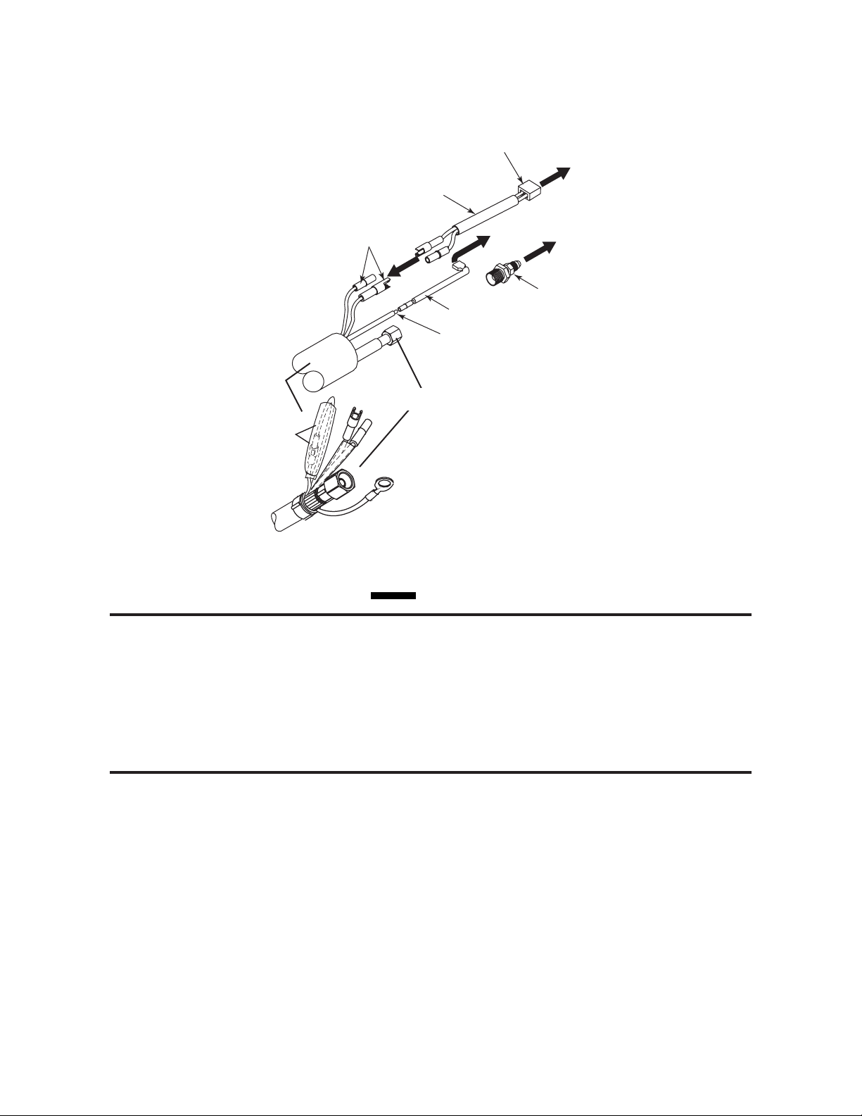
Control Connector
y
or
S
Wires with Connectors
Two-Pin
Connector
To Power Suppl
Control Connect
orch Lead
ssembies
Joined and
leeved Wires
Torch Control
Connectors
Negative/Plasma Lead
To Power Supply
Pilot Connector
Adapter Fitting
Pilot Lead Adapter
Pilot Lead With
Ring T erminal Removed
CAUTION
To Power Supply
(-) Fitting
Art # A-04213
Refer to the illstration above. Torch leads may include two wires connected with mating connectors and covered
with an insulation sleeve. On these leads the wires must remain covered and connected in hand tor ch applications.
7. Connect the Negative/Plasma Lead from the replacement torch to the Adapter Fitting. Slide the protective
boot over the lead connection.
8. Connect the Control Connector Wire (see NOTE) to the two mating connectors on the replacement torch
leads to the two mating connectors on the replacement torch leads.
NOTE
For Mechanized Systems refer to the Torch Control Cable Wiring Diagram in the Manual supplied with the RPT
Torch.
9. Connect the fastons of the Control Connector Wires to the Power Supply. Install the two replacement tiewraps in the same location as noted in Step 3 above to secure the control and pilot leads to the existing
wiring.
October 6 , 2004 2 Manual 0-2832
Page 3

10. Reinstall any covers removed (see WARNING).
WARNING
Make sure that the Control Connector Wires DO NOT contact the Adapter Fitting after all leads are connected.
11. Install the proper torch consumables for the Power Supply amperage.
12. Reconnect main input power to the Power Supply and turn the unit ON.
13. Set air pressure to 60 - 70 psi (4.1 - 4.8 bar).
14. T est torch for proper operation.
This completes the installation instructions.
NOTE
Every effort has been made to provide complete and accurate information in this manual. However, the
publisher does not assume and hereby disclaims any liability to any party for any loss or damage caused
by errors or omissions in this manual, whether such errors result fr om negligence, accident or any other
cause.
October 6 , 2004 3 Manual 0-2832
 Loading...