

Page 1
!
Manual 0-2498
Optional Transformer Module
For ULTIMA-150 Plasma Welder
Catalog # 7-3315
Instruction Sheet
General Information
The Ultima 150 Transformer Module is a step down transformer which converts 575V primary power to 460V for
use with the Ultima 150 Plasma Welding System. The
transformer module is shipped with a 460V output
power cable attached. The primary input power cable
must be supplied by the user.
These instruction are supplied to ensure the proper installation of the Transformer Module. It is recommended
to thoroughly read the instructions first, before attempting the installation of the module.
WARNING
The transformer module is intended for use with
the Ultima 150 Plasma Welding System only.
Specifications
Primary Input Power:
Voltage
Phase
Current 7.5 Amps
Fuse Size 10 Amps (recommended)
Input Power Cable 12/4 (recommended)
Output 460V, Three Phase
Weight Approximately 45 lbs.
Dimensions:
Height
Width
Length
Hertz
575V + - 10%
Three Phase
60 Hz
5.5 Inches
15 inches
24 inches
Supplied Parts
The following parts are supplied:
• Transformer Module (1 each)
• 1/4-20 x 5/8 Hex Self Tapping Bolts (6 each)
• Black Plastic Snap Bushing Inserts (2 each)
Installation Procedure
W ARNING
Disconnect primary power at the source before assembling or disassembling the transformer module.
1. Remove the Transformer Module from the shipping
package.
2. Remove the cover from the Ultima 150 Power Supply.
3. Locate the two 0.875 inch diameter knockouts in the
base of the Ultima 150 Power Supply. The knockouts
are located on the left hand side of the unit just behind
and below the ON/OFF circuit breaker.
4. Remove the two knockouts by inserting a philips screw
driver into the hole in the center of the knockout and
prying out and downward.
5. Insert the two black plastic bushings (supplied) into
the knockout holes in the Ultima 150 Power Supply
base.
6. Place the Ultima 150 Power Supply on top of the Transformer Module so that the front of the power supply
is oriented in the same direction as the two terminal
blocks inside the Transformer Module. The front of
the power supply should be directly above the two
terminal blocks.
7. Loosen the strain relief on the rear of the Ultima 150
Power Supply and insert the input power cable
through the strain relief.
Date: 11/17/95 1 Manual 0-2498
Page 2
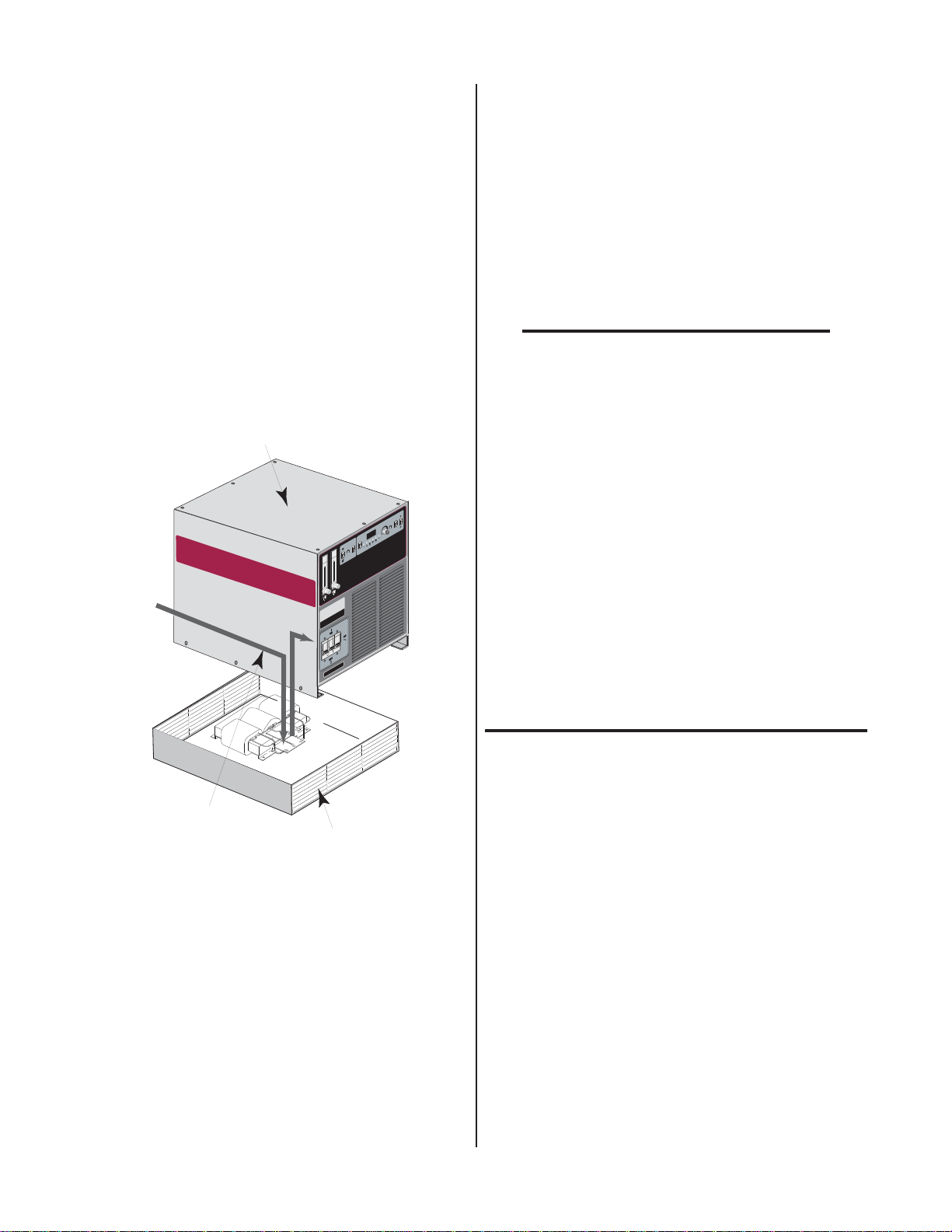
8. Route the input power cable down through the bushing
closest to the rear of the Ultima 150 Power Supply installed in Step 5 above.
14. Pull the excess slack in the input power cable up out of
the bushing in the Ultima 150 Power Supply base and
out through the strain relief. Tighten the strain relief.
9. Connect the three AC wires from the input power cable
to terminals 1, 2 and 3 of the left hand terminal block in
the Transformer Module.
10. Connect the ground wire in the input power cable to
the ground stud on the base of the Transformer Module.
11. In the Transformer Module route the four wires, one
green/yellow and three black wires (labeled 1, 2 &
3), connected to the right hand terminal block up
through the bushing closest to the front of the Ultima 150 Power Supply installed in Step 5 above.
Ultima-150 Power Supply
L
E
N
A
P
E
G
N
A
R
0
5
1
5
T
N
E
T
I
R
M
I
R
L
U
E
T
C
O
M
E
R
5
1
5
.
0
A
V
/
A
A
C
D
T
O
L
I
P
A
L
O
O
C
S
A
G
A
W
E
P
I
V
M
E
E
T
R
P
C
A
C
R
W
A
E
I
T
V
E
O
R
L
P
I
P
T
N
E
R
R
C
U
R
C
A
S
T
L
VO
N
O
V
A
A
A
M
S
A
L
P
T
E
D
S
L
E
I
H
S
575 VAC
Input
A
S
U
ade In
M
15. Pull the three black and one ground wire up through
the bushing in the Ultima 150 Power Supply base.
16. Connect the ground wire to the ground stud in the
base of the Ultima 150 Power Supply.
17. Connect the black wires to the top studs on the rear of
the front panel Ultima 150 Power Supply ON/OFF circuit breaker per the following:
NOTE
Location of studs are viewed looking at the rear of
the circuit breaker.
a. Black wire labeled '1' to top left stud.
b. Black wire labeled '2' to top center stud.
c. Black wire labeled '3' to top right stud.
18. Replace the cover on the Ultima 150 Power Supply.
NOTE
Every effort has been made to provide complete and accurate information in this manual.
However, the publisher does not assume and
hereby disclaims any liability to any party for
any loss or damage caused by errors or omissions in this Manual, whether such errors result from negligence, accident, or any other
cause.
Power Cable Routing
(Inside Power Supply)
Transformer Module
Figure 1 Input Power Cable Routing
12. Lift the Ultima 150 Power Supply enough to slide it
forward so that the three holes in both sides of the
Ultima 150 Power Supply base line up with the three
holes in each side of the Transformer Module.
13. Install one each of the 1/4-20 bolts (supplied) into
each of the six holes. These are self threading bolts
and may require a little extra force the first time they
are installed.
Manual 0-2498 Instruction Sheet 11/95
Date: 11/17/95 2 Manual 0-2498
 Loading...