

Page 1

Plasma Cutting
Master Power Supply
CE MERLIN ® 6000
A-01497
Operating Manual
August 19, 2005 Manual No. 0-2601
Page 2

Page 3

WARNINGS
Read and understand this entire Manual and your employer’s safety practices before installing, operating, or servicing the equipment.
While the information contained in this Manual represents the Manufacturer's best judgement, the
Manufacturer assumes no liability for its use.
Plasma Cutting Master Power Supply
CE Merlin 6000
Operating Manual No. 0-2601
Published by:
Thermal Dynamics Corporation
82 Benning Street
West Lebanon, New Hampshire, USA 03784
(603) 298-5711
www.thermadyne.com
©Copyright 1997 by
Thermal Dynamics Corporation
All rights reserved.
Reproduction of this work, in whole or in part, without written permission of the publisher is prohibited.
The publisher does not assume and hereby disclaims any liability to
any party for any loss or damage caused by any error or omission in
this Manual, whether such error results from negligence, accident, or
any other cause.
Printed in the United States of America
Publication Date: August 19, 2005
Record the following information for Warranty purposes:
Where Purchased: _______________________________________
Purchase Date: _______________________________________
Power Supply Serial #: _______________________________________
Torch Serial #: _______________________________________
Page 4

TABLE OF CONTENTS
SECTION 5:
CUSTOMER/OPERA T OR SER VICE.................................................................................. 5-1
5.01 Introduction ................................................................................................... 5-1
5.02 General Maintenance .................................................................................... 5-1
5.03 Common Operating Faults ............................................................................ 5-2
5.04 Troubleshooting ............................................................................................ 5-2
5.05 Basic Parts Replacement ............................................................................. 5-5
SECTION 6:
P AR TS LISTS .................................................................................................................... 6-1
6.01 Introduction ................................................................................................... 6-1
6.02 Ordering Information...................................................................................... 6-1
6.03 Complete Power Supply Replacement Parts List .......................................... 6-2
6.04 Basic Component Replacement Parts List.................................................... 6-3
6.05 Power Supply Options And Accessories ....................................................... 6-4
APPENDIX 1: INPUT WIRING REQUIREMENTS....................................................................... A-1
APPENDIX 2: SEQUENCE OF OPERATION
BLOCK DIAGRAM............................................................................................................. A-2
APPENDIX 3: TYPICAL MECHANIZED SYSTEM W ORK AND GROUND CABLE CONNECTIONSA-3
APPENDIX 4: TYPICAL MECHANIZED SYSTEM CABLE INTERCONNECTION DIAGRAM ...... A-4
APPENDIX 5: QUICK REFERENCE T O INTERCONNECTING CABLES AND HOSES ..............A-6
APPENDIX 6: INTERF A CE CABLE FOR REMOTE CONTROL (RC6010) .................................. A-7
APPENDIX 7: INTERF A CE CABLE FOR ST ANDOFF CONTROL (SC11)................................... A-8
APPENDIX 8: CNC INTERF A CE CABLES................................................................................. A-9
APPENDIX 9: LADDER DIA GRAM - 120 VAC ......................................................................... A-10
APPENDIX 10-A: LADDER DIAGRAM - 15 vdc
(Rev AE or Earlier Logic Control PC Board)...................................................................... A-11
APPENDIX 10-B: LADDER DIAGRAM - 15 vdc
(Rev AF or Later Logic Control PC Board) ........................................................................ A-12
APPENDIX 11: PARALLEL CABLE ......................................................................................... A-13
APPENDIX 12: ROUTINE MAINTENANCE SCHEDULE ..........................................................A-14
APPENDIX 13: SYSTEM SCHEMATIC - Rev 'B' or Earlier .......................................................A-16
APPENDIX 14: SYSTEM SCHEMATIC - Rev 'AK' or Later .....................................................A-18
Page 5

TABLE OF CONTENTS (continued)
SECTION 5:
CUSTOMER/OPERA T OR SERVICE.................................................................................. 5-1
5.01 Introduction................................................................................................... 5-1
5.02 General Maintenance.................................................................................... 5-1
5.03 Common Operating F aults ............................................................................ 5-2
5.04 Troubleshooting............................................................................................. 5-2
5.0 5 Basic Parts Replacement ............................................................................. 5-5
SECTION 6:
PARTS LISTS ................................................................................................................... 6-1
6.01 Introduction................................................................................................... 6-1
6.02 Ordering Information ..................................................................................... 6-1
6.0 3 Complete Pow er Supply Replacement Parts List .......................................... 6-2
6.0 4 Basic Component Replacement Parts List.................................................... 6- 3
6.0 5 Po wer Supply Options And Accessories....................................................... 6-4
APPENDIX 1: INPUT WIRING REQUIREMENTS ..................................................................... A-1
APPENDIX 2: SEQUENCE OF OPERATION BLOCK DIAGRAM .............................................A-2
APPENDIX 3: TYPICAL MECHANIZED SYSTEM WORK AND GROUND
CABLE CONNECTIONS....................................................................................................A-3
APPENDIX 4: TYPICAL MECHANIZED SYSTEM CABLE INTERCONNECTION DIAGRAM ...A-4
APPENDIX 5: Q UICK REFERENCE T O INTERCONNECTING CABLES AND HOSES ............ A-6
APPENDIX 6: INTERF A CE CABLE FOR REMOTE CONTR OL (RC6010) .................................A-7
APPENDIX 7: INTERF A CE CABLE FOR STANDOFF CONTROL (SC11) .................................A-8
APPENDIX 8: CNC INTERFACE CABLES................................................................................ A-9
APPENDIX 9: LADDER DIA GRAM - 120 VAC ........................................................................ A-10
APPENDIX 10-A: LADDER DIAGRAM - 15 vdc (Rev AE or Earlier Logic Control PC Board) ..A-11
APPENDIX 10-B: LADDER DIAGRAM - 15 vdc (Rev AF or Later Logic Control PC Board)..... A-12
APPENDIX 11: PARALLEL CABLE......................................................................................... A-13
APPENDIX 12: ROUTINE MAINTENANCE SCHEDULE......................................................... A-14
APPENDIX 13: SYSTEM SCHEMATIC - Rev 'B' or Earlier...................................................... A-16
APPENDIX 14: SYSTEM SCHEMATIC - Rev 'C' or Later........................................................ A-18
Page 6

Page 7

SECTION 1:
GENERAL INFORMATION
1.01 Notes, Cautions and Warnings
Throughout this manual, notes, cautions, and warnings
are used to highlight important information. These highlights are categorized as follows:
NOTE
An operation, procedure, or backgr ound information which requires additional emphasis or is helpful in efficient operation of the system.
CAUTION
A procedure which, if not properly followed, may
cause damage to the equipment.
WARNING
A procedure which, if not properly followed, may
cause injury to the operator or others in the operating area.
1.02 Important Safety Precautions
WARNINGS
OPERATION AND MAINTENANCE OF
PLASMA ARC EQUIPMENT CAN BE DANGEROUS AND HAZARDOUS TO YOUR
HEAL TH.
Plasma arc cutting produces intense electric and
magnetic emissions that may interfere with the
proper function of cardiac pacemakers, hearing
aids, or other electronic health equipment. Persons who work near plasma arc cutting applications should consult their medical health professional and the manufacturer of the health
equipment to determine whether a hazard exists.
To prevent possible injury, read, understand and
follow all warnings, safety precautions and instructions before using the equipment. Call 1-603298-5711 or your local distributor if you have any
questions.
GASES AND FUMES
Gases and fumes produced during the plasma cutting
process can be dangerous and hazardous to your health.
• Keep all fumes and gases from the breathing area.
Keep your head out of the welding fume plume.
• Use an air-supplied respirator if ventilation is not
adequate to remove all fumes and gases.
• The kinds of fumes and gases from the plasma arc
depend on the kind of metal being used, coatings
on the metal, and the different processes. Y ou must
be very careful when cutting or welding any metals which may contain one or more of the following:
Antimony Chromium Mercury
Arsenic Cobalt Nickel
Barium Copper Selenium
Beryllium Lead Silver
Cadmium Manganese Vanadium
• Always read the Material Safety Data Sheets
(MSDS) that should be supplied with the material
you are using. These MSDSs will give you the information regarding the kind and amount of fumes
and gases that may be dangerous to your health.
• For information on how to test for fumes and gases
in your workplace, refer to item 1 in Subsection 1.03,
Publications in this manual.
• Use special equipment, such as water or down draft
cutting tables, to capture fumes and gases.
• Do not use the plasma torch in an area where combustible or explosive gases or materials are located.
• Phosgene, a toxic gas, is generated from the vapors
of chlorinated solvents and cleansers. Remove all
sources of these vapors.
• This product, when used for welding or cutting,
produces fumes or gases which contain chemicals
known to the State of California to cause birth defects and, in some cases, cancer . (California Health
& Safety Code Sec. 25249.5 et seq.)
ELECTRIC SHOCK
Electric Shock can injure or kill. The plasma arc process
uses and produces high voltage electrical energy. This
electric energy can cause severe or fatal shock to the operator or others in the workplace.
• Never touch any parts that are electrically “live”
or “hot.”
Date: January 27, 2004 1-1 GENERAL INFORMATION
Page 8
• Wear dry gloves and clothing. Insulate yourself
from the work piece or other parts of the welding
circuit.
• Repair or replace all worn or damaged parts.
• Extra care must be taken when the workplace is
moist or damp.
• Install and maintain equipment according to NEC
code, refer to item 9 in Subsection 1.03, Publications.
• Disconnect power source before performing any
service or repairs.
• Read and follow all the instructions in the Operating Manual.
FIRE AND EXPLOSION
Fire and explosion can be caused by hot slag, sparks, or
the plasma arc.
• Be sure there is no combustible or flammable material in the workplace. Any material that cannot
be removed must be protected.
• Ventilate all flammable or explosive vapors from
the workplace.
• Do not cut or weld on containers that may have
held combustibles.
• Provide a fire watch when working in an area where
fire hazards may exist.
• Hydrogen gas may be formed and trapped under
aluminum workpieces when they are cut underwater or while using a water table. DO NOT cut
aluminum alloys underwater or on a water table
unless the hydrogen gas can be eliminated or dissipated. T rapped hydrogen gas that is ignited will
cause an explosion.
NOISE
Noise can cause permanent hearing loss. Plasma arc processes can cause noise levels to exceed safe limits. Yo u
must protect your ears from loud noise to prevent permanent loss of hearing.
• T o protect your hearing from loud noise, wear pr otective ear plugs and/or ear muffs. Protect others
in the workplace.
• Noise levels should be measured to be sure the decibels (sound) do not exceed safe levels.
• For information on how to test for noise, see item 1
in Subsection 1.03, Publications, in this manual.
PLASMA ARC RA YS
Plasma Arc Rays can injure your eyes and burn your skin.
The plasma arc process produces very bright ultra violet
and infra red light. These arc rays will damage your
eyes and burn your skin if you are not properly pr otected.
• To protect your eyes, always wear a welding helmet or shield. Also always wear safety glasses with
side shields, goggles or other protective eye wear.
• Wear welding gloves and suitable clothing to protect your skin from the arc rays and sparks.
• Keep helmet and safety glasses in good condition.
Replace lenses when cracked, chipped or dirty.
• Protect others in the work area from the arc rays.
Use protective booths, screens or shields.
• Use the shade of lens as suggested in the following
per ANSI/ASC Z49.1:
Minimum Protective Suggested
Arc Current Shade No. Shade No.
Less Than 300* 8 9
300 - 400* 9 12
400 - 800* 10 14
* These values apply where the actual arc is clearly
seen. Experience has shown that lighter filters
may be used when the arc is hidden by the workpiece.
1.03 Publications
Refer to the following standards or their latest revisions
for more information:
1. OSHA, SAFETY AND HEAL TH STANDARDS, 29CFR
1910, obtainable from the Superintendent of Documents, U.S. Government Printing Office, Washington,
D.C. 20402
2. ANSI Standard Z49.1, SAFETY IN WELDING AND
CUTTING, obtainable from the American Welding Society, 550 N.W. LeJeune Rd, Miami, FL 33126
3. NIOSH, SAFETY AND HEALTH IN ARC WELDING
AND GAS WELDING AND CUTTING, obtainable
from the Superintendent of Documents, U.S. Government Printing Office, Washington, D.C. 20402
4. ANSI Standard Z87.1, SAFE PRACTICES FOR OCCUP ATION AND EDUCA TIONAL EYE AND FACE PROTECTION, obtainable from American National Standards Institute, 1430 Broadway, New York, NY 10018
5. ANSI Standard Z41.1, STANDARD FOR MEN’S
SAFETY -TOE FOOTWEAR, obtainable from the American National Standards Institute, 1430 Broadway, New
York, NY 10018
GENERAL INFORMATION 1-2 Date: January 27, 2004
Page 9
6. ANSI Standard Z49.2, FIRE PREVENTION IN THE USE
OF CUTTING AND WELDING PROCESSES, obtainable from American National Standards Institute, 1430
Broadway, New York, NY 10018
7. AWS Standar d A6.0, WELDING AND CUTTING CONTAINERS WHICH HAVE HELD COMBUSTIBLES, obtainable from American Welding Society, 550 N.W.
LeJeune Rd, Miami, FL 33126
8. NFPA Standard 51, OXYGEN-FUEL GAS SYSTEMS
FOR WELDING, CUTTING AND ALLIED PROCESSES, obtainable from the National Fire Protection
Association, Batterymarch Park, Quincy, MA 02269
9. NFPA Standard 70, NATIONAL ELECTRICAL CODE,
obtainable from the National Fire Protection Association, Batterymarch Park, Quincy, MA 02269
10. NFPA Standard 51B, CUTTING AND WELDING PROCESSES, obtainable from the National Fire Protection
Association, Batterymarch Park, Quincy, MA 02269
11. CGA Pamphlet P-1, SAFE HANDLING OF COMPRESSED GASES IN CYLINDERS, obtainable from the
Compressed Gas Association, 1235 Jefferson Davis
Highway, Suite 501, Arlington, VA 22202
12. CSA Standard W117.2, CODE FOR SAFETY IN WELDING AND CUTTING, obtainable from the Canadian
Standards Association, Standards Sales, 178 Rexdale
Boulevard, Rexdale, Ontario, Canada M9W 1R3
13. NWSA booklet, WELDING SAFETY BIBLIOGRAPHY
obtainable from the National Welding Supply Association, 1900 Arch Street, Philadelphia, PA 19103
14. American W elding Society Standar d A WSF4.1, RECOMMENDED SAFE PRACTICES FOR THE PREPARATION FOR WELDING AND CUTTING OF CONT AINERS AND PIPING THAT HAVE HELD HAZARDOUS
SUBSTANCES, obtainable fr om the American Welding
Society, 550 N.W. LeJeune Rd, Miami, FL 33126
ATTENTION
Toute procédure pouvant résulter
l’endommagement du matériel en cas de nonrespect de la procédur e en question.
AVERTISSEMENT
Toute procédure pouvant provoquer des blessures
de l’opérateur ou des autres personnes se trouvant
dans la zone de travail en cas de non-respect de la
procédure en question.
1.05 Precautions De Securite Importantes
AVERTISSEMENTS
L’OPÉRATION ET LA MAINTENANCE DU
MATÉRIEL DE SOUDAGE À L’ARC AU JET
DE PLASMA PEUVENT PRÉSENTER DES
RISQUES ET DES DANGERS DE SANTÉ.
Coupant à l’arc au jet de plasma produit de l’énergie
électrique haute tension et des émissions
magnétique qui peuvent interférer la fonction
propre d’un “pacemaker” cardiaque, les appareils
auditif, ou autre matériel de santé electronique.
Ceux qui travail près d’une application à l’arc au
jet de plasma devrait consulter leur membre
professionel de médication et le manufacturier de
matériel de santé pour déterminer s’il existe des
risques de santé.
15. ANSI Standard Z88.2, PRACTICE FOR RESPIRATORY
PROTECTION, obtainable from American National
Standards Institute, 1430 Broadway, New York, NY
10018
1.04 Note, Attention et
Avertissement
Dans ce manuel, les mots “note,” “attention,” et
“avertissement” sont utilisés pour mettre en relief des
informations à caractère important. Ces mises en relief
sont classifiées comme suit :
NOTE
Toute opération, procédure ou renseignement
général sur lequel il importe d’insister davantage
ou qui contribue à l’efficacité de fonctionnement
du système.
Date: January 27, 2004 1-3 GENERAL INFORMATION
Il faut communiquer aux opérateurs et au personnel TOUS les dangers possibles. Afin d’éviter les
blessures possibles, lisez, comprenez et suivez tous
les avertissements, toutes les précautions de sécurité
et toutes les consignes avant d’utiliser le matériel.
Composez le + 603-298-5711 ou votr e distributeur
local si vous avez des questions.
FUMÉE et GAZ
La fumée et les gaz produits par le procédé de jet de
plasma peuvent présenter des risques et des dangers de
santé.
Page 10
• Eloignez toute fumée et gaz de votre zone de respiration. Gardez votre tête hors de la plume de fumée
provenant du chalumeau.
• Utilisez un appareil respiratoire à alimentation en air
si l’aération fournie ne permet pas d’éliminer la fumée
et les gaz.
• Ne touchez jamais une pièce “sous tension” ou “vive”;
portez des gants et des vêtements secs. Isolez-vous
de la pièce de travail ou des autres parties du circuit
de soudage.
• Réparez ou remplacez toute pièce usée ou
endommagée.
• Les sortes de gaz et de fumée provenant de l’arc de
plasma dépendent du genre de métal utilisé, des
revêtements se trouvant sur le métal et des différ ents
procédés. Vous devez prendre soin lorsque vous
coupez ou soudez tout métal pouvant contenir un ou
plusieurs des éléments suivants:
antimoine cadmium mercure
argent chrome nickel
arsenic cobalt plomb
baryum cuivre sélénium
béryllium manganèse vanadium
• Lisez toujours les fiches de données sur la sécurité
des matières (sigle américain “MSDS”); celles-ci
devraient être fournies avec le matériel que vous
utilisez. Les MSDS contiennent des renseignements
quant à la quantité et la nature de la fumée et des gaz
pouvant poser des dangers de santé.
• Pour des informations sur la manière de tester la
fumée et les gaz de votre lieu de travail, consultez
l’article 1 et les documents cités à la page 5.
• Utilisez un équipement spécial tel que des tables de
coupe à débit d’eau ou à courant descendant pour
capter la fumée et les gaz.
• N’utilisez pas le chalumeau au jet de plasma dans une
zone où se trouvent des matières ou des gaz combustibles ou explosifs.
• Le phosgène, un gaz toxique, est généré par la fumée
provenant des solvants et des produits de nettoyage
chlorés. Eliminez toute source de telle fumée.
• Ce produit, dans le procéder de soudage et de coupe,
produit de la fumée ou des gaz pouvant contenir des
éléments reconnu dans L’état de la Californie, qui
peuvent causer des défauts de naissance et le cancer .
(La sécurité de santé en Californie et la code sécurité
Sec. 25249.5 et seq.)
CHOC ELECTRIQUE
• Prenez des soins particuliers lorsque la zone de travail est humide ou moite.
• Montez et maintenez le matériel conformément au
Code électrique national des Etats-Unis. (V oir la page
5, article 9.)
• Débranchez l’alimentation électrique avant tout travail d’entretien ou de réparation.
• Lisez et respectez toutes les consignes du Manuel de
consignes.
INCENDIE ET EXPLOSION
Les incendies et les explosions peuvent résulter des scories
chaudes, des étincelles ou de l’arc de plasma. Le procédé
à l’arc de plasma produit du métal, des étincelles, des
scories chaudes pouvant mettre le feu aux matières combustibles ou provoquer l’explosion de fumées
inflammables.
• Soyez certain qu’aucune matière combustible ou inflammable ne se trouve sur le lieu de travail. Protégez
toute telle matière qu’il est impossible de retirer de la
zone de travail.
• Procurez une bonne aération de toutes les fumées
inflammables ou explosives.
• Ne coupez pas et ne soudez pas les conteneurs ayant
pu renfermer des matières combustibles.
• Prévoyez une veille d’incendie lors de tout travail dans
une zone présentant des dangers d’incendie.
• Le gas hydrogène peut se former ou s’accumuler sous
les pièces de travail en aluminium lorsqu’elles sont
coupées sous l’eau ou sur une table d’eau. NE PAS
couper les alliages en aluminium sous l’eau ou sur
une table d’eau à moins que le gas hydrogène peut
s’échapper ou se dissiper . Le gas hydrogène accumulé
explosera si enflammé.
Les chocs électriques peuvent blesser ou même tuer. Le
RAYONS D’ARC DE PLASMA
procédé au jet de plasma requiert et produit de l’éner gie
électrique haute tension. Cette énergie électrique peut
produire des chocs graves, voire mortels, pour l’opérateur
et les autres personnes sur le lieu de travail.
Les rayons provenant de l’arc de plasma peuvent blesser
vos yeux et brûler votre peau. Le procédé à l’arc de
plasma produit une lumière infra-rouge et des rayons
GENERAL INFORMATION 1-4 Date: January 27, 2004
Page 11

ultra-violets très forts. Ces rayons d’arc nuiront à vos
yeux et brûleront votre peau si vous ne vous protégez
pas correctement.
• Pour protéger vos yeux, portez toujours un casque ou
un écran de soudeur . Portez toujours des lunettes de
sécurité munies de parois latérales ou des lunettes de
protection ou une autre sorte de protection oculair e.
• Portez des gants de soudeur et un vêtement protecteur
approprié pour protéger votre peau contre les
étincelles et les rayons de l’arc.
• Maintenez votre casque et vos lunettes de protection
en bon état. Remplacez toute lentille sale ou
comportant fissure ou rognure.
• Protégez les autres personnes se trouvant sur la zone
de travail contre les rayons de l’arc en fournissant des
cabines ou des écrans de protection.
• Utilisez la nuance de lentille qui est suggèrée dans le
recommendation qui suivent ANSI/ASC Z49.1:
Nuance Minimum Nuance Suggerée
Courant Arc Protective Numéro Numéro
Moins de 300* 8 9
300 - 400* 9 12
400 - 800* 10 14
* Ces valeurs s’appliquent ou l’arc actuel est observé
clairement. L’experience a démontr er que les filtres
moins foncés peuvent être utilisés quand l’arc est
caché par moiceau de travail.
1.06 Documents De Reference
Consultez les normes suivantes ou les révisions les plus
récentes ayant été faites à celles-ci pour de plus amples
renseignements :
1. OSHA, NORMES DE SÉCURITÉ DU TRA VAIL ET DE
PROTECTION DE LA SANTÉ, 29CFR 1910,
disponible auprès du Superintendent of Documents,
U.S. Government Printing Office, Washington, D.C.
20402
2. Norme ANSI Z49.1, LA SÉCURITÉ DES
OPÉRATIONS DE COUPE ET DE SOUDAGE,
disponible auprès de la Société Américaine de
Soudage (American Welding Society), 550 N.W.
LeJeune Rd., Miami, FL 33126
3. NIOSH, LA SÉCURITÉ ET LA SANTÉ LORS DES
OPÉRATIONS DE COUPE ET DE SOUDAGE À
L’ARC ET AU GAZ, disponible auprès du Superintendent of Documents, U.S. Government Printing
Office, Washington, D.C. 20402
4. Norme ANSI Z87.1, PRATIQUES SURES POUR LA
PROTECTION DES YEUX ET DU VISAGE AU TRAV AIL ET DANS LES ECOLES, disponible de l’Institut
Américain des Normes Nationales (American National Standards Institute), 1430 Broadway, New York,
NY 10018
5. Norme ANSI Z41.1, NORMES POUR LES
CHAUSSURES PROTECTRICES, disponible auprès
de l’American National Standards Institute, 1430
Broadway, New York, NY 10018
BRUIT
Le bruit peut provoquer une perte permanente de l’ouïe.
Les procédés de soudage à l’arc de plasma peuvent
provoquer des niveaux sonores supérieurs aux limites
normalement acceptables. V ous dú4ez vous pr otéger les
oreilles contre les bruits forts afin d’éviter une perte
permanente de l’ouïe.
• Pour protéger votre ouïe contre les bruits forts, portez
des tampons protecteurs et/ou des protections
auriculaires. Protégez également les autres personnes
se trouvant sur le lieu de travail.
• Il faut mesurer les niveaux sonores afin d’assurer que
les décibels (le bruit) ne dépassent pas les niveaux
sûrs.
• Pour des renseignements sur la manière de tester le
bruit, consultez l’article 1, page 5.
6. Norme ANSI Z49.2, PRÉVENTION DES INCENDIES
LORS DE L ’EMPLOI DE PROCÉDÉS DE COUPE ET
DE SOUDAGE, disponible auprès de l’American National Standards Institute, 1430 Broadway, New Y ork,
NY 10018
7. Norme A6.0 de l’Association Américaine du Soudage
(AWS), LE SOUDAGE ET LA COUPE DE
CONTENEURS A YANT RENFERMÉ DES PRODUITS
COMBUSTIBLES, disponible auprès de la American
Welding Society, 550 N.W. LeJeune Rd., Miami, FL
33126
8. Norme 51 de l’Association Américaine pour la Protection contre les Incendies (NFPA), LES SYSTEMES
À GAZ AVEC ALIMENTATION EN OXYGENE
POUR LE SOUDAGE, LA COUPE ET LES
PROCÉDÉS ASSOCIÉS, disponible auprès de la National Fire Protection Association, Batterymar ch Park,
Quincy, MA 02269
Date: January 27, 2004 1-5 GENERAL INFORMATION
Page 12

9. Norme 70 de la NFPA, CODE ELECTRIQUE NATIONAL, disponible auprès de la National Fire Protection Association, Batterymarch Park, Quincy, MA
02269
10. Norme 51B de la NFPA, LES PROCÉDÉS DE
COUPE ET DE SOUDAGE, disponible auprès de la
National Fire Protection Association, Batterymarch
Park, Quincy, MA 02269
11. Brochure GCA P-1, LA MANIPULATION SANS
RISQUE DES GAZ COMPRIMÉS EN CYLINDRES,
disponible auprès de l’Association des Gaz
Comprimés (Compressed Gas Association), 1235
Jefferson Davis Highway, Suite 501, Arlington, VA
22202
12. Norme CSA W117.2, CODE DE SÉCURITÉ POUR
LE SOUDAGE ET LA COUPE, disponible auprès
de l’Association des Normes Canadiennes, Standards Sales, 178 Rexdale Boulevard, Rexdale,
Ontario, Canada, M9W 1R3
13. Livret NWSA, BIBLIOGRAPHIE SUR LA
SÉCURITÉ DU SOUDAGE, disponible auprès de
l’Association Nationale de Fournitures de Soudage
(National Welding Supply Association), 1900 Arch
Street, Philadelphia, PA 19103
14. Norme AWSF4.1 de l’Association Américaine de
Soudage, RECOMMANDA TIONS DE PRA TIQUES
SURES POUR LA PRÉPARATION À LA COUPE ET
AU SOUDAGE DE CONTENEURS ET TUYAUX
AYANT RENFERMÉ DES PRODUITS
DANGEREUX , disponible auprès de la American
Welding Society, 550 N.W. LeJeune Rd., Miami, FL
33126
15. Norme ANSI Z88.2, PRATIQUES DE PROTECTION
RESPIRATOIRE, disponible auprès de l’American
National Standards Institute, 1430 Broadway, New
York, NY 10018
GENERAL INFORMATION 1-6 Date: January 27, 2004
Page 13

1.07 Declaration of Conformity
S
Manufacturer: Thermal Dynamics Corporation
Address: 82 Benning Street
W est Lebanon, New Hampshire 03784
USA
The equipment described in this manual conforms to all applicable aspects and regulations of the ‘Low Voltage Directive’
(European Council Directive 73/23/EEC as amended by Council Directive 93/68/EEC) and to the National legislation for
the enforcement of this Directive.
The equipment described in this manual conforms to all applicable aspects and regulations of the "EMC Directive" (European Council Directive 89/336/EEC) and to the National legislation for the enforcement of this Directive.
Serial numbers are unique with each individual piece of equipment and details description, parts used to manufacture a unit
and date of manufacture.
National Standard and Technical Specifications
The product is designed and manufactured to a number of standards and technical r equirements. Among them ar e:
* CSA (Canadian Standards Association) standard C22.2 number 60 for Arc welding equipment.
* UL (Underwriters Laboratory) rating 94VO flammability testing for all printed-circuit boar ds used.
* ISO/IEC 60974-1 (BS 638-PT10) (EN 60 974-1) (EN50192) (EN50078) applicable to plasma cutting equipment and
associated accessories.
* CENELEC EN50199 EMC Product Standard for Arc Welding Equipment
* For environments with increased hazard of electrical shock, Power Supplies bearing the
EN50192 when used in conjunction with hand torches with exposed tips, if equipped with properly installed standoff guides.
* Extensive product design verification is conducted at the manufacturing facility as part of the routine design and
manufacturing process. This is to ensure the product is safe, when used according to instructions in this manual and
related industry standards, and performs as specified. Rigorous testing is incorporated into the manufacturing
process to ensure the manufactured product meets or exceeds all design specifications.
Thermal Dynamics has been manufacturing products for more than 30 years, and will continue to achieve excellence in our
area of manufacture.
Manufacturers responsible repr esentative: Steve W ard
Operations Director
Thermadyne Europe
Europa Building
Chorley N Industrial Park
Chorley, Lancashire,
England PR6 7BX
mark conform to
Date: January 27, 2004 1-7 GENERAL INFORMATION
Page 14

1.08 Statement of Warranty
LIMITED WARRANTY: Thermal Dynamics® Corporation (hereinafter “Thermal”) warrants that its products will be free of defects in
workmanship or material. Should any failure to conform to this warranty appear within the time period applicable to the Thermal
products as stated below , Thermal shall, upon notification thereof and substantiation that the product has been stor ed, installed, operated,
and maintained in accordance with Thermal’s specifications, instructions, recommendations and recognized standard industry practice,
and not subject to misuse, repair , neglect, alteration, or accident, corr ect such defects by suitable r epair or replacement, at Thermal’s sole
option, of any components or parts of the product determined by Thermal to be defective.
THIS W ARRANTY IS EXCLUSIVE AND IS IN LIEU OF ANY WARRANTY OF MERCHANTABILITY OR FITNESS FOR A PAR TICULAR
PURPOSE.
LIMIT A TION OF LIABILITY : Thermal shall not under any circumstances be liable for special or consequential damages, such as, but not
limited to, damage or loss of purchased or replacement goods, or claims of customers of distributor (hereinafter “Purchaser”) for service
interruption. The remedies of the Purchaser set forth herein are exclusive and the liability of Thermal with respect to any contract, or
anything done in connection therewith such as the performance or breach thereof, or from the manufacture, sale, delivery, resale, or use of
any goods covered by or furnished by Thermal whether arising out of contract, negligence, strict tort, or under any warranty , or otherwise,
shall not, except as expressly provided herein, exceed the price of the goods upon which such liability is based.
THIS WARRANTY BECOMES INVALID IF REPLACEMENT PA RTS OR ACCESSORIES ARE USED WHICH MAY IMPAIR THE
SAFETY OR PERFORMANCE OF ANY THERMAL PRODUCT.
THIS WARRANTY IS INVALID IF THE PRODUCT IS SOLD BY NON-AUTHORIZED PERSONS.
The limited warranty periods for Thermal products shall be as follows (with the exception of XL Plus Series, CutMaster Series , Cougar
and DRAG-GUN): A maximum of three (3) years from date of sale to an authorized distributor and a maximum of two (2) years from
date of sale by such distributor to the Purchaser, and with the further limitations on such two (2) year period (see chart below).
The limited warranty period for XL Plus Series and CutMaster Series shall be as follows: A maximum of four (4) years from date
of sale to an authorized distributor and a maximum of three (3) years from date of sale by such distributor to the Purchaser, and
with the further limitations on such three (3) year period (see chart below).
The limited warranty period for Cougar and DRAG-GUN shall be as follows: A maximum of two (2) years from date of sale to an
authorized distributor and a maximum of one (1) year from date of sale by such distributor to the Purchaser, and with the further
limitations on such two (2) year period (see chart below).
Parts
XL Plus & Parts Parts
PAK Units, Power Supplies CutMaster Series Cougar/Drag-Gun All Others Labor
Main Power Magnetics 3 Y ears 1 Year 2 Years 1 Year
Original Main Power Rectifier 3 Y ears 1 Year 2 Years 1 Year
Control PC Board 3 Y ears 1 Year 2 Years 1 Year
All Other Circuits And Components Including, 1 Year 1 Y ear 1 Y ear 1 Year
But Not Limited To, Starting Circuit,
Contactors, Relays, Solenoids, Pumps,
Power Switching Semi-Conductors
Consoles, Control Equipment, Heat 1 Y ear 1 Y ear 1 Year
Exchanges, And Accessory Equipment
Torch And Leads
Maximizer 300 Torch 1 Y ear 1 Year
SureLok T orches 1 Y ear 1 Y ear 1 Year
All Other Torches 180 Days 180 Days 180 Days 180 Days
Repair/Replacement Parts 90 Days 90 Days 90 Days None
Warranty repairs or replacement claims under this limited warranty must be submitted by an authorized Thermal Dynamics® repair
facility within thirty (30) days of the repair . No transportation costs of any kind will be paid under this warranty. Transportation charges
to send products to an authorized warranty repair facility shall be the responsibility of the customer. All returned goods shall be at the
customer ’s risk and expense. This warranty supersedes all previous Thermal warranties.
Effective: November 15, 2001
GENERAL INFORMATION 1-8 Date: January 27, 2004
Page 15
SECTION 2:
INTRODUCTION &
DESCRIPTION
2.01 Scope of Manual
This manual contains descriptions, operating instructions and
basic maintenance procedures for the Merlin 6000 Plasma Cutting CE Master Power Supply . Service of this equipment is
restricted to Thermal Dynamics trained personnel; unqualified
personnel are strictly cautioned against attempting repairs or
adjustments not covered in this manual, at the risk of voiding
the W arranty .
Read this manual thoroughly . A complete understanding of the
characteristics and capabilities of this equipment will assure
the dependable operation for which it was designed.
NOTE
This Manual may include references to the Power
Supply revision letter(s). There are old style and
new style data tags that may be encountered. The
old style data tag has the revision letter(s) at the
end of the serial number. The new style data tag
has the revision letter(s) in an area marked 'Rev'.
2.02 General Description
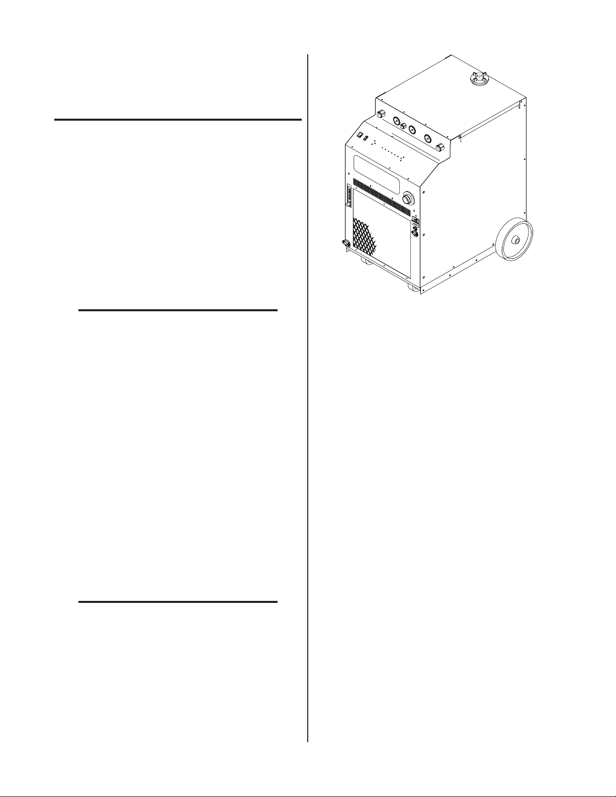
The Master Power Supply contains all operator controls,
electrical and gas inputs and outputs, and the torch leads
receptacle. A Slave Power Supply may be connected in
parallel to double the cutting capacity (amperage) of the Master Power Supply . All signal inputs/outputs, gas, and torch
connections are still connected to the Master Power Supply
when the Slave Power Supply is used. The Slave Power Supply
has the same power circuits as the Master Power Supply . The
Master Power Supply can also be connected to a second Master Power Supply and the equipment will automatically be configured when the parallel cable is installed. Many options and
accessories can be added to further improve the versatility of
the system.
A-01497
Figure 2-1 Power Supply
The 'Extra-CoolTM' Coolant supplied with the Power Supply can be used in ambient temperatures down to 10° F
(-12° C). If the ambient temperature will be below 10° F
(-12° C) use 'Ultra-CoolTM' Coolant. This coolant can be
used in areas where the ambient temperature drops to -27°
F (-33° C).
A typical system configuration will contain the following:
• One or two CE Power Supplies with Running Gear
• Arc Starter Box
• Maximizer 300 Machine Torch with Leads and
Mounting Assembly
• T or ch Supply Leads
• Maximizer 300 Spare Parts Kit
• 25 ft (7.6 m) W ork Cable and Ring Lug
• Optional Air Line Filter Assembly (or) High Pressure Regulators
NOTES
Refer to the Merlin 6000 Plasma Cutting CE Slave
Power Supply Operating Manual 0-2603 for more
information on the Slave Power Supply.
The Merlin 6000 CE Slave Power Supply requires
a Merlin 6000 CE Master Power Supply for proper
operation and torch connections.
Manual 0-2601 2-1 INTRODUCTION & DESCRIPTION
Page 16
2.03 Specifications & Design
Temperature
Features
5. Duty Cycle (see NOTE)
NOTE
The following apply to the Master Power Supply only:
1. Controls
ON/OFF Switch, Output Current Control, RUN/SET/PURGE
Switch, Secondary Gas Regulator , Plasma Gas Regulator,
Secondary Mode Switch, Secondary W ater Flowmeter/
Regulator , Optional Arc Hour/Counter Meters
2. Control Indicators
LED Indicators:
AC , TEMP , GAS, DC, PILOT, COOLANT PRES, and COOL-
ANT COND
Gauges:
Secondary , Plasma, and Coolant Pressure Gauges
3. Input Power
Voltage Frequency Phase Amperage
380 50 or 60 Hz 3 51
415 50 or 60 Hz 3 47
NOTE
Refer to Appendix 1 for recommended input wiring size, current ratings, and circuit pr otection requirements.
Amperage depends on input voltage (Refer to Appendix 1).
4. Output Power
Master Power Supply:
Continuously adjustable by potentiometer from 50
to 150 amps
With Slave Power Supply:
Continuously adjustable by potentiometer from
100 to 300 amps
The duty cycle will be reduced if the primary input
voltage (AC) is low or the DC voltage is higher
than shown in the chart.
Power Supply Duty Cycle
Ambient
Duty Cy cle
Current
DC Vol ta g e
6. Pilot Modes
Auto-Restart, Pre-Flow Delay , "Recycle Required"
7. CNC Signals
Enable, Start/Stop, OK-T o-Move, Pilot Sensing Relay (PSR),
Full CNC A vailable with Remote
8. Coolant Pressure
Internal Service-adjustable
130 psi (8.8 bar) at zero flow
120 - 125 psi (8.2 - 8.5 bar) at 0.6 gpm (2.6 lpm)
9. Coolant Flow Rate
0.5 gpm (2.2 lpm) with 150 feet of total torch and torch leads
at 70°F (21°C)
The flow rate varies with lead length, torch configuration, ambient temperature, amperage level,
etc.
10. Cooling Capacity
4,000 to 10,000 BTU
Maximum value based on “free flow” condition.
104° F (40° C)
100%
150 Amps
140 vdc
NOTE
NOTE
11. Coolant Reservoir Capacity
2 gallons
Capable of handling a total of 150 feet of torch lead
length
INTRODUCTION & DESCRIPTION 2-2 Manual 0-2601
Page 17

12. Secondary Water
C. Pilot Arc
T ap water can be used as a secondary gas and must be
capable of delivering the following minimums:
• Water pr essure of 50 psi (3.5 bar)
• Flow of 8 gph (35.2 lph)
NOTES
Tap water should only be used as a secondary gas
on machine torches.
The tap water source does not need to be deionized,
but in water systems with extremely high mineral
content a water softener is recommended.
13. Power Supply Dimensions
Enclosure Only -
Width: 24.12 in (0.61 m)
Height: 38.38 in (0.98 m)
Depth: 34.25 in (0.87 m)
Fully Assembled -
Width: 28.50 in (0.72 m)
Height: 43.38 in (1.10 m)
Depth: 43.75 in (1.11 m)
14. W eight of Power Supply Only
When the torch is activated there is a two second gas pr e-flow,
followed by a uninterrupted DC pilot arc established between
the electrode and tip. The pilot arc is initiated by a momentary
high frequency pulse from the Arc Starter Box. The pilot creates a path for the main arc to transfer to the work. When the
main arc is established, the pilot arc shuts off. The pilot automatically restarts when the main arc stops, as long as the torch
remains activated.
NOTE
For the arc to restart automatically, AUTO RESTART must be enabled at switch settings inside
the Power Supply (Refer to Section 4.07).
D. Main Cutting Arc
The Power Supply accepts 50 or 60 Hz three-phase line
input. The power supply converts AC input power to
DC power for the main cutting arc. The negative output
is connected to the torch electrode through the negative
torch lead. The positive output is connected to the workpiece via the work cable and ring lug connection.
E. RF Shielding
All machine torch systems are shielded to minimize radio frequency (RF) interference which results from the
high frequency arc initiation. These shielded systems are
designed with features such as a wire for establishing an
earth ground and shielded torch and control leads.
678 lbs (308 kg)
2.04 Theory Of Operation
A. Plasma Arc Cutting and Gouging
Plasma is a gas which is heated to an extremely high temperature and ionized so that it becomes electrically conductive. The plasma arc cutting process uses this plasma
gas to transfer an electric arc to a workpiece. The metal
to be cut is melted by the intense heat of the arc and then
blown away by the flow of gas. Plasma arc gouging uses
the same process to remove material to a controlled depth
and width.
With a simple change of torch parts, the system can also
be used for plasma arc gouging. Plasma arc gouging is
used to remove material to a controlled depth and width.
B
. Input and Output Power
The Power Supply accepts input voltages of 380/415V,
50 or 60 Hz, three-phase. The unit converts AC input
power to DC power for the main cutting arc. The negative output is connected to the torch electrode through
the negative torch lead, and the positive output connects
to the workpiece through the work cable.
F. Interlocks
The system has several built-in interlocks to provide safe
and efficient operation. When an interlock shuts down
the system, the fault condition must be remedied and the
system recycled using the applicable control device.
1. Parts-In-Place (PIP) Interlock
The Power Supply has a built-in parts-in-place interlock that prevents accidental torch starting when
torch parts are not properly installed. A flow switch
on the coolant return lead detects reduced coolant
flow caused by improper torch assembly. If not satisfied, the switch interrupts power to the tip and electrode.
2. Gas Pressure Interlock
A pr essure switch acts as an interlock for the plasma
gas supply. If the supply pressure falls below minimum requirements the pressure switch will open,
shutting off the power to the contactors, and the GAS
indicator will go out. When adequate supply pressure is available the pressure switch will close, allowing power to be resumed for cutting.
Manual 0-2601 2-3 INTRODUCTION & DESCRIPTION
Page 18

3. Thermal Interlock
C. Computer Control Cable Kits
Thermal overload sensors are located in the transformer ,
pilot resistors, and main heatsink in the power supply . If
one of these components is overheated the appropriate
switch will open, causing the temperature light to turn from
green to red and shutting of f power to the main contactor.
When the overheated component cools down the switch
will close again and allow operation of the system.
G. Plasma Torches
Plasma torches are similar in design to the common automotive
spark plug. They consist of negative and positive sections
which are separated by a center insulator . Inside the torch, the
pilot arc is initiated in the gap between the negatively charged
electrode and the positively charged tip. Once the pilot arc has
ionized the plasma gas, the superheated column of gas flows
through the small orifice in the torch tip, which is focused on
the metal to be cut.
The Maximizer 300 T orch uses an internal closed-loop cooling
system. Deionized coolant is distributed from a reservoir in the
Power Supply through the coolant supply lead. At the tor ch,
the coolant is circulated through the torch tip and electrode,
where the extra cooling helps to prolong parts life. Coolant
then circles back to the power supply through the return lead.
The Maximizer 300 also can use secondary gases such as compressed air , nitrogen (N2), water , and carbon dioxide (CO
).
2
2.05 Options And Accessories
These items can be used to customize a standard system for a
particular application or to further enhance performance. T orch
accessories are listed in the separate T orch Instruction Manual.
For interfacing the power supply with a computer or auxiliary control device. A vailable in various cable lengths.
D. High Pressure Regulators
A vailable for air, oxygen, ar gon/hydrogen, nitrogen, CO2,
and water .
E. High Flow Water Shield (HFWS) Assembly
Reduces arc glare, noise, and fumes during the cutting
process.
F. Two Stage Air Line Filter
Removes damaging contaminants as small as 5 microns
from the plasma stream when using compr essed air.
G. Hour/Counter Meters
Meter assembly containing two meters. One meter indicates the total number of hours and minutes that the main
cutting arc has been on to a maximum of 99999-59 (hoursminutes). The second meter counts the number of times
that the cutting arc has been started to a maximum of
99999999 starts. Both meters can be reset to zero.
H. Plasma/Secondary Gas Control (GC 3000)
A remote control to select one of various plasma and secondary gases that can be connected to the Power Supply .
This allows one-time plumbing connections of various gas/
water supplies. The operator has complete flexibility to
quickly select the best plasma and secondary gas combinations for the metal to be cut.
NOTE
Refer to Section 6, Parts Lists, for ordering information.
A. RC6010 Remote Control
For mechanized systems, this low profile unit provides full CNC capability and allows the operator to
control all system functions from a remote location.
B. SC-10 or SC11 Standoff Controls
For machine torch systems, the Standoff Control automatically finds height and maintains torch standoff with a high
speed torch lifter motor .
NOTES
Standoff Control SC10 must be used with the Remote Control RC6010.
Standoff Control SC11 can be used without Remote Control RC6010.
INTRODUCTION & DESCRIPTION 2-4 Manual 0-2601
Page 19

SECTION 3:
3.03 Unpacking
INSTALLATION
3.01 Introduction
This Section describes installation of the Master Power
Supply. These instructions apply to the Master Power
Supply Assemblies only; installation procedur es for Slave
Power Supply, Options and Accessories are given in
Manuals specifically provided for those units.
The complete installation consists of:
1. Site selection
2. Unpacking
3. Connections to Power Supply
a. Input power
b. Internal power selection
c. Work cable
d. Gas connections
e. Torch Installation
Each component of the system is packaged separately and protected with a carton and packing material to prevent damage
during shipping. Components are packaged as follows:
A. Power Supply
The power supply is skid-mounted and protected with a carton
and padding material to prevent damage during shipment. The
power supply with work cable are factory-assembled and packaged together. Also packed with the system are:
• Tor ch and torch leads
• Tor ch Supply Leads
• Spare parts kit for the torch
• Coolant deionizing bag
• Arc Starter Box
• Operating Manual for Power Supply
B. Torches
T orches and leads are packaged with the Power Supply . Spare
parts for new torches are packed in a spare parts box. Separate
instruction manual is provided with each torch.
C. Options and Accessories
f. Connecting auxiliary devices
4. Grounding
5. Operator training
3.02 Site Location
Select a clean, dry location with good ventilation and adequate working space around all components.
CAUTION
Operation without proper air flow will inhibit
proper cooling and reduce duty cycle.
The Master Power Supply is cooled by air flow through
the front, rear, and side panels. Air flow must not be obstructed. At least 2 feet (0.61 m) of clearance should be
provided on all sides.
NOTE
When using the Slave Power Supply in parallel
with the Master Power Supply the supplies should
be placed next to each other. Placing one Power
Supply behind the other will cause heated air to be
drawn into the rear Power Supply. This condition
may lower the duty cycle of the system.
Options and Accessories are packaged separately fr om the
Power Supply .
D. Unpacking Procedure
1. Unpack each item and remove all packing material.
2. Locate the packing list(s) and use the list to identify
and account for each item.
3. Inspect each item for possible shipping damage. If
damage is evident, contact your distributor before proceeding with installation.
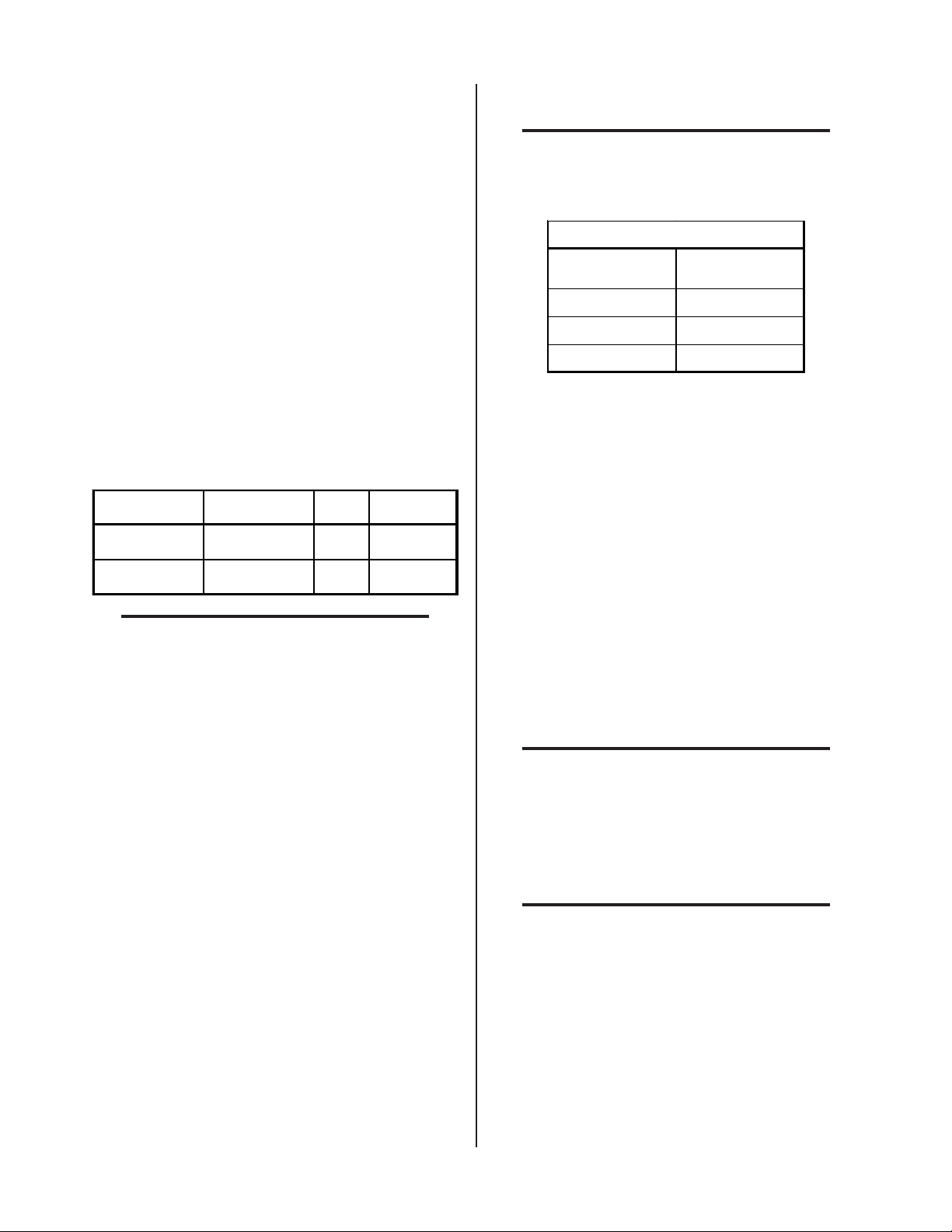
3.04 Removing Skid
The Power Supply is mounted on the skid with two brackets.
Remove the Power Supply from the skid as follows:
1. Remove the six bolts connecting the brackets to the base of
the Power Supply .
Review the safety precautions in the front of this manual
to be sure that the location meets all safety requirements.
Manual 0-2601 3-1 INSTALLA TION PROCEDURES
Page 20
s
)
Shipping Brackets
ir
r
2. Remove the coolant filler cap from the reservoir at the
top rear of the Power Supply .
3. Place the deionizer bag into the basket in the coolant
reservoir .
Coolant Reservo
Filler Cap
Deionizer
Bag
Basket
A-01498
Shipping Pallet
Three Bolt
(Each Side
Figure 3-1 Skid Removal From Power Supply
2. Roll the Power Supply off the skid backwards (rear wheels
first).
3.05 Filling Master Power Supply
Coolant
NOTE
Only the Master Power Supply requires coolant.
DO NOT install coolant in the Slave Power Supply or the second Master Power Supply if used.
The ambient temperature of the environment where the
Power Supply will be located determines the coolant to be
used. The Standard T or ch Coolant supplied with the system can be used in ambient temperatures down to 10° F
(-12° C).
Optional Super T orch Coolant should be used in areas wher e
the ambient temperature drops down to -27° F (-33° C)
CAUTION
A-00872
Coolant Level Indicato
Figure 3-2 Coolant Reservoir
4. Carefully pour enough of the supplied Thermal Arc
T orch Coolant into the reservoir to fill it to the FULL
mark on the rear panel.
NOTE
After operating the system more coolant may need
to be added. Allow the pump to operate for ten
minutes to properly purge any air from the coolant
lines before using the system.
5. Reinstall the reservoir coolant filler cap.
3.06 Input Power Connections
The Power Supply accepts input voltages of 380/415V,
50 or 60 Hz, three-phase power.
Use only Thermal Arc Torch Coolant. Use of any
other coolant can result in torch damage, insufficient thermal protection, and/or pilot arc interference.
A. Electrical Connections
The power source must conform to local electric code and
the recommended circuit protection and wiring r equirements shown in Appendix 1.
1. Locate the coolant deionizer bag and remove from
the plastic shipping bag.
INSTALLA TION PROCEDURES 3-2 Manual 0-2601
Page 21
B. Opening Power Supply Enclosure
n
11
12
L3
13
15
14
6
7
L2
8
10
9
1
2
L1
3
5
4
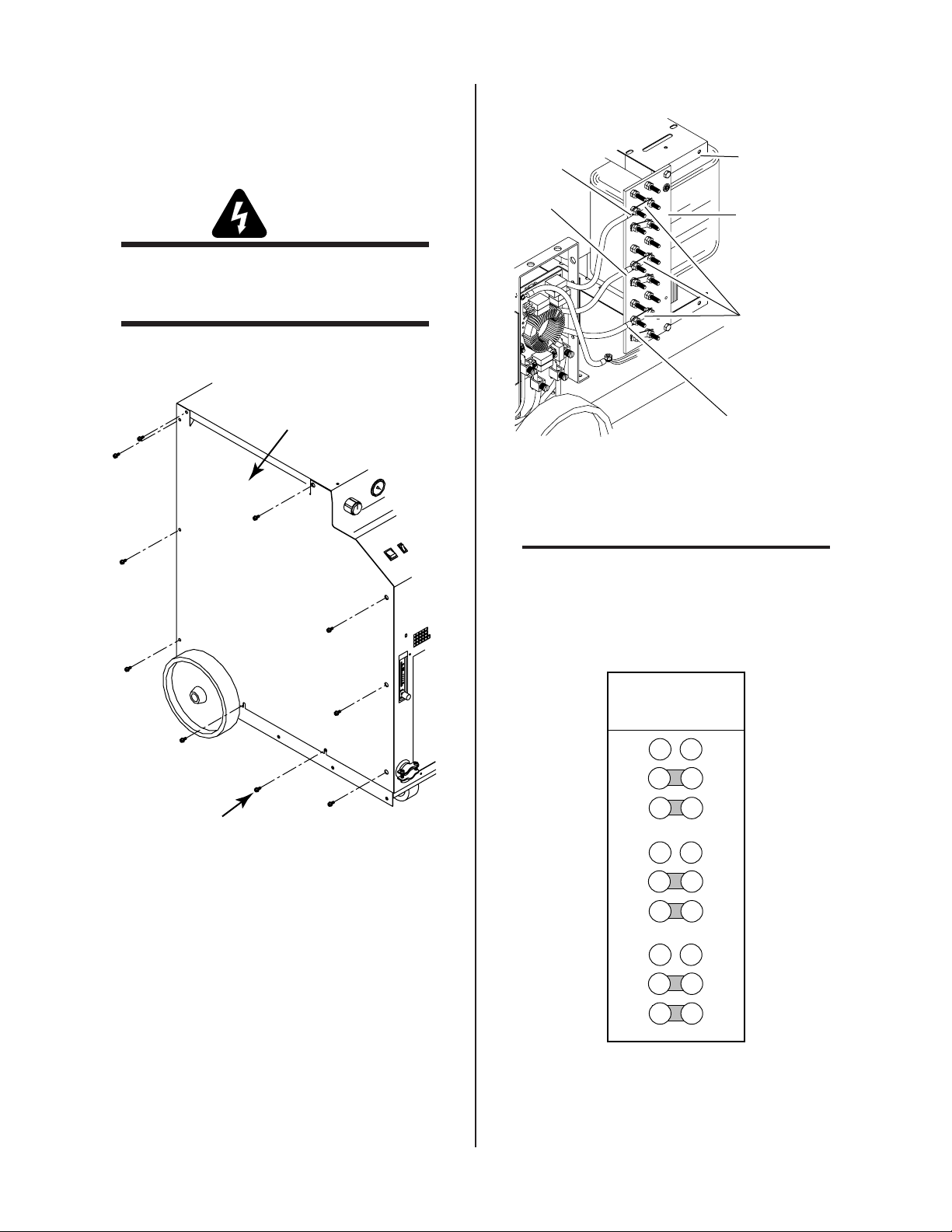
Busbar Connections
For Input Voltage
Of 380/415 VAC
A-01090
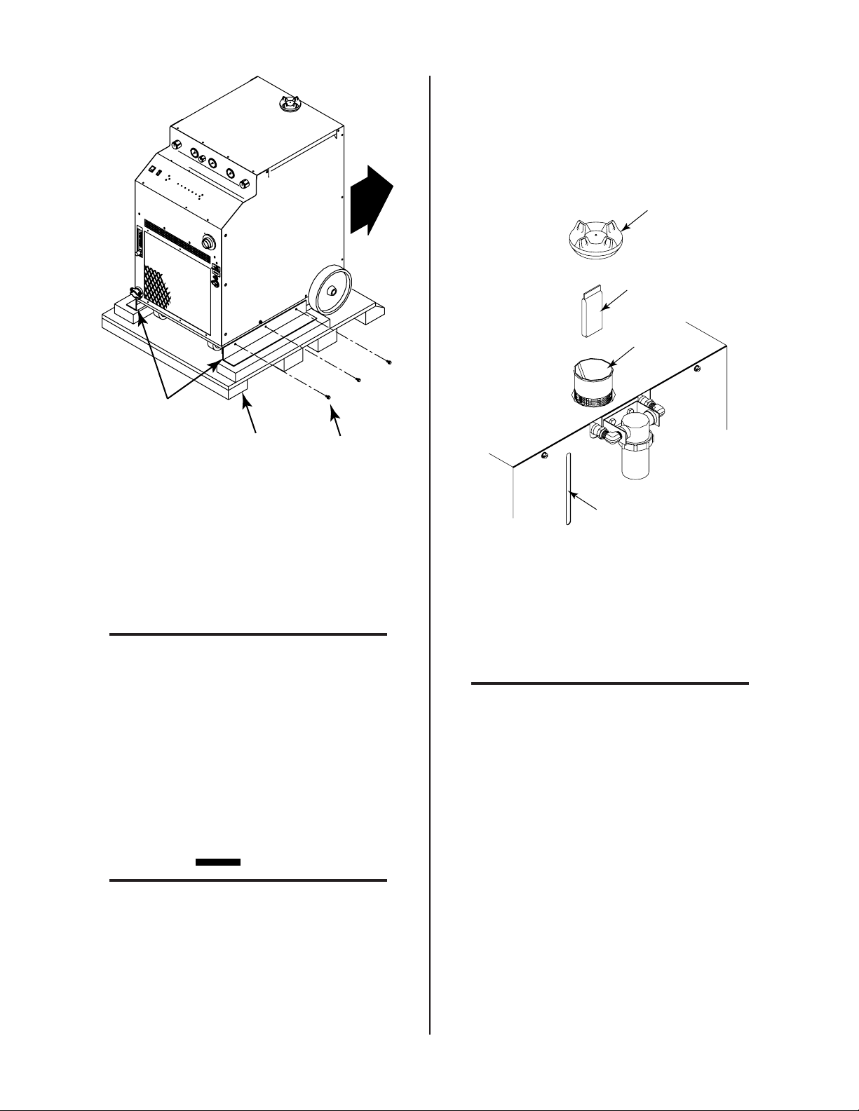
The left side panel (viewed from the front) of the Power Supply
must be removed to make electrical connections and to select
the proper input voltage.
L3
Extra Busbar
Storage Locatio
W ARNING
Disconnect primary power at the source before
assembling or disassembling power supply, torch
parts, or torch and leads assemblies.
1. Remove the ten screws which secure the left side panel
(viewed from the front) to the Power Supply .
Left Side Panel
L2
A-01091
Input Voltage
Terminal Board
Busbars
L1
Figure 3-4 Input Voltage Terminal Board Location
NOTE
Extra busbars are attached (stored) to the top
side of the power transformer assembly.
2. Check the busbar configuration on the input voltage
terminal board . The busbar configuration must correspond with the available line voltage per the following
figure and the label inside the unit:
2. Remove the left side panel from the Power Supply.
3.07 Checking Input Connections
The Power Supply is wired to use input voltages of
380/415 VAC. Internal busbars must be checked on the
input voltage terminal board to verify proper installation
.
1. Locate the input voltage terminal board on the
Manual 0-2601 3-3 INSTALLA TION PROCEDURES
Screws
(10 Places)
Figure 3-3 Opening Power Supply
left side of the power supply.
A-01535
Figure 3-5 Busbar Connections
If necessary , reposition the busbars to correspond to the
available line voltage.
Page 22
3.08 Primary Power Cable
P
C
g
g
Connections
WARNING
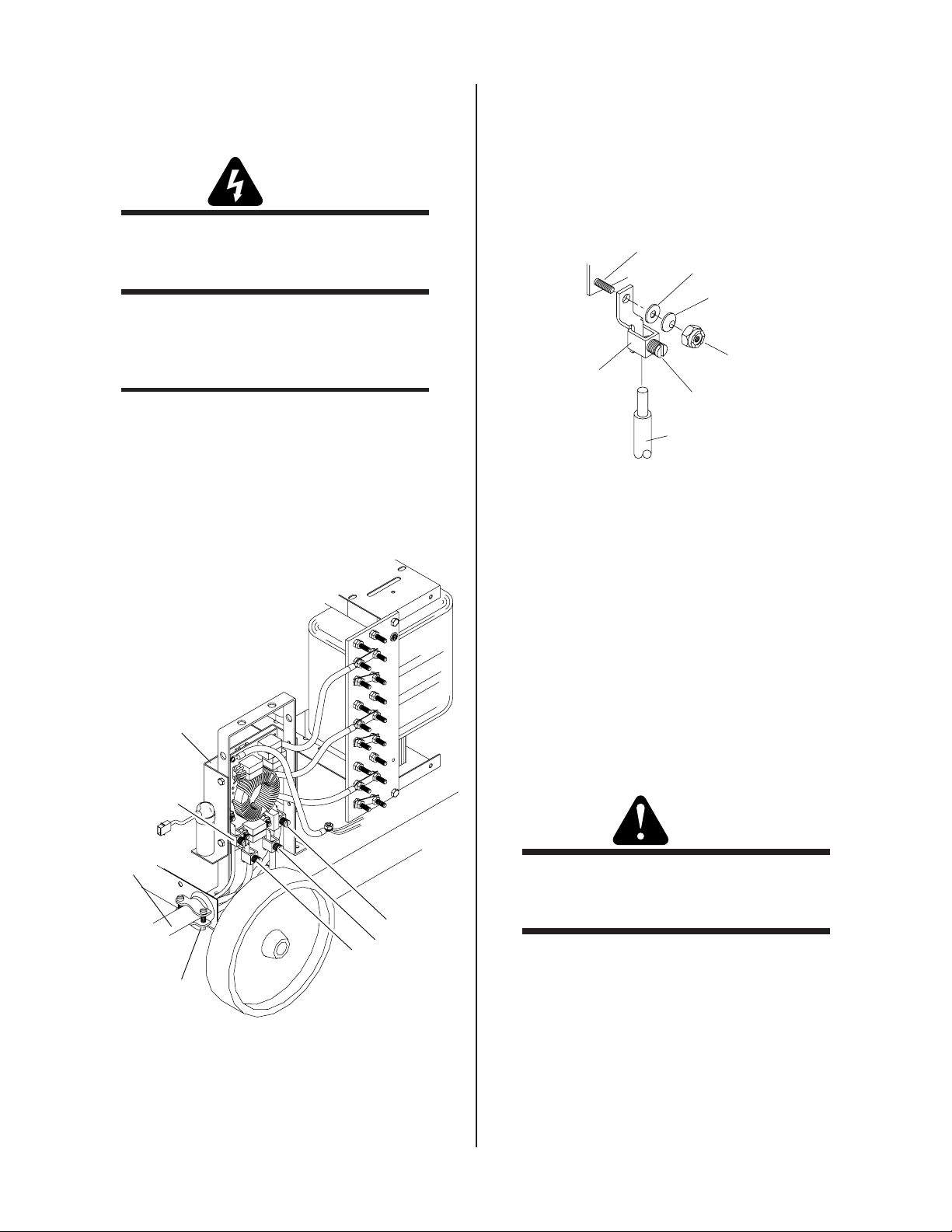
2. Locate the four input connectors, flat washers, conical
spring washers, and hex locking nuts supplied with the
power supply .
3. Install the input connectors, supplied, onto each of the
input power line leads of the power cable.
Disconnect primary power at the source before connecting the primary power cable to the power supply.
The primary power cable must be supplied by the end
user and installed to the Power Supply assembly. Recommended cable sizes are specified in Appendix 1.
NOTE
Three-phase operation requires a 3-conductor cable
with ground.
1. Route the primary power cable through the strain
relief fitting in the rear panel of the Power Supply and tighten strain relief screws.
PC Board
Power Stud
Flat Washer
Conical Sprin
Washer
Hex Lockin
Input
onnector
A-00908
Slotted Screw
Input Power Cable
(One Line)
Nut
Figure 3-7 Input Voltage Connector Installation Detail
4. Connect the input power connectors to the EMI Input
Power Filter PC Board input studs with the supplied
hex locking nuts, conical spring washers, and flat washers as follows:
• Input ground wire to G1.
• LI input line to X1.
Input Power
Filter PC Board
and Bracket
• L2 input line to Y1.
• L3 input line to Z1.
5. Tighten the nuts being careful not to over-tighten. Refer
to the following W ARNING.
Input Ground
Connection
W ARNING
rimary Power
Cable
Do Not over tighten the nuts securing the input
power cable connectors as damage to the PC Board
L3
L2
L1
Strain Relief
Fitting
A-00896
can occur.
Figure 3-6 Input Voltage Connections
INSTALLA TION PROCEDURES 3-4 Manual 0-2601
Page 23

3.09 Ground Connections For Mechanized Applications
NOTE
Refer to Appendix 3 for a block diagram of a typical mechanized system work and ground cable connections.
A. Electromagnetic Interference (EMI)
Pilot arc initiation generates a certain amount of electromagnetic interference (EMI), commonly called RF noise.
This RF noise may interfere with other electronic equipment such as CNC controllers, remote controls, height
controllers, etc. T o minimize RF interference, follow these
grounding procedures when installing mechanized systems:
B. Grounding
1. The preferred gr ounding arrangement is a single point
or “Star” ground. The single point, usually on the
cutting table, is connected with 1/0 AWG (50.0 mm
European) or larger wire to a good earth ground (refer to paragraph ‘C’, Creating An Earth Ground). The
ground rod must be placed as close as possible to the
cutting table, ideally less than 10 ft (3.0 m), but no
more than 20 ft (6.1 m).
NOTE
All ground wires should be as short as possible.
Long wires will have increased resistance to RF
frequencies. Smaller diameter wire has increased
resistance to RF frequencies, so using a larger diameter wire is better .
2. G rounding for components mounted on the cutting
table (CNC controllers, height controllers, plasma remote controls, etc.) should follow the manufacturer’s
recommendations for wire size, type, and connection
point locations.
For Thermal Dynamics components it is recommended to use a minimum of 10 AWG (6.00 mm2 European) wire or flat copper braid with cross section
equal to or greater than 10 AWG connected to the cutting table frame. The connection point must be clean
bare metal; rust and paint make poor connections. For
all components, wires larger than the recommended
minimum can be used and may improve noise protection.
3. The cutting machine frame is then connected to the
“Star” point using 1/0 A WG (50.0 mm
larger wire.
2
European) or
4. The plasma power supply work cable (see NOTE) is connected to the cutting table at the single point “Star” ground.
NOTE
Do Not connect the work cable directly to the
ground rod.
5. Make sure work cable and ground cables are properly connected. The work cable must have a solid
connection to the cutting table. The work and ground
connections must be free from rust, dirt, grease, oil
and paint. If necessary grind or sand down to bare
metal. Use lock washers to keep the connections tight.
Using electrical joint compound to prevent corrosion
is also recommended.
6. The plasma power supply chassis is connected to the
power distribution system ground as required by electrical codes. If the plasma supply is close to the cutting table (see NOTE) a second ground rod is not usually needed, in fact it could be detrimental as it can
set up ground loop currents that cause interference.
2
When the plasma power supply is far away from the
ground rod and interference is experienced, it may
help to install a second earth ground rod next to the
plasma power supply. The plasma power supply
chassis would then be connected to this ground rod.
NOTE
It is recommended that the Plasma Power Supply
be within 20 - 30 ft (6.1 – 9.1 m) of the cutting
table, if possible.
7. The plasma control cable should be shielded with the
shield connected only at the cutting machine end.
Connecting the shield at both ends will allow ground
loop currents which may cause more interfer ence than
with no shield at all.
C. Creating An Earth Ground
1. To create a solid, low resistance, earth gr ound, drive a
1/2 in (12 mm) or greater diameter copper clad ground
rod at least 6 - 8 ft (1.8 - 2.4 m) into the earth so that
the rod contacts moist soil over most of its length.
Depending on location, a greater depth may be required to obtain a low resistance ground (see NOTE).
Ground rods, typically 10 ft (3.0 m) long, may be
welded end to end for greater lengths. Locate the rod
as close as possible to the work table. Install a ground
wire, 1/0 AWG (50.0 mm2 European) or greater, between the ground rod and the star ground point on
the cutting table.
NOTE
Ideally, a properly installed ground r od will have a
resistance of three ohms or less.
Manual 0-2601 3-5 INSTALLA TION PROCEDURES
Page 24
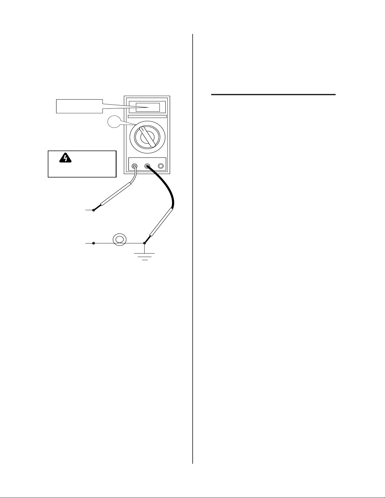
T o test for a proper earth ground, refer to the following
A
d
diagram. Ideally , the reading on the multimeter should be
as follows:
3.10 Plasma And Secondary Gas
Connections
• For 115VAC: 3.0 VAC
• For 230VAC: 1.5 VAC
115VAC: 3.0 VAC
230VAC: 1.5 VAC
~
Meter set to
VAC setting
WARNING
Use extreme caution. This
test uses live voltage.
Neutral
115 or 230VAC
Line (Hot)
rt # A-02971
V
100W
Light Bulb
~
V
VR COM A
_
+
Groun
Rod
Ground Testing
2. Increasing the ground rod length beyond 20 - 30 ft
(6.1 – 9.1 m) does not generally increase the effectiveness of the ground rod. A larger diameter rod which
has more surface area may help. Sometimes keeping
the soil around the ground rod moist by continuously
running a small amount of water into it will work.
Adding salt to the soil by soaking it in salt water may
also reduce its resistance. When these methods are
used, periodic checking of the ground resistance is required to make sure the ground is still good.
The Master Power Supply provides the liquid cooling and
gases to support operation of the Liquid Cooled Maximizer 300 Torch.
NOTE
Refer to the Liquid Cooled Maximizer 300 Torch
Instruction Manual (Cat. No. 0-2573 for information on plasma and secondary gas selection and
requirements.
The following are available gases that can be used with
the Liquid Cooled Maximizer 300 Torch:
Plasma Gases: Compressed Air, Oxygen (O
), Nitro-
2
gen (N2), or Argon/Hydrogen (Ar/H2)
Secondary Gases: Compressed Air, Nitrogen (N2),
Carbon Dioxide (CO
), or T ap Water (refer to follow-
2
ing note)
Plasma and secondary requirements vary depending on
the application. The plasma and secondary gases are
connected to the rear panel connections of the power supply. Depending on the options installed and the source
of the gases will determine the installation of filters and
regulators.
This sub-section includes information for connecting the
gas supplies to the Power Supply. The information is
grouped in paragraphs for different types of gases and
options per the following:
A. Using Shop Air
B. Using High-Pressure Gas Cylinders
C. Using W ater Secondary
D. Plasma and Secondary Gases With Gas Control
Option
Refer to the appropriate paragraph(s) for the desired application to be used.
D. Routing Of Torch Leads
1. To minimize RF interference, position torch leads as
far as possible from any CNC components, drive motors, control cables, or primary power lines. If cables
have to pass over torch leads, do so at an angle. Do
not run the plasma control or other control cables in
parallel with the torch leads in power tracts.
2. Keep torch leads clean. Dirt and metal particles bleed
off energy, which causes difficult starting and increased chance of RF interference.
INSTALLA TION PROCEDURES 3-6 Manual 0-2601
Page 25

A. Using Shop Air
g
M
An inline pneumatic dryer/evaporator type air filter , capable of
filtering particulates to at least 5 microns with a dew point of
35°F (1.7°C), is required when using air from a compr essor. This
type filter will insure that moisture, oil, dirt, chips, rust particles,
and other contminants from the supply hose do not enter the
torch. For highly automated applications, a refrigerated drier
plus a particulate filter may be used to chill the air to remove all
moisture.
CAUTION
Excessive oil or moisture in compressed air will
reduce torch parts life and cutting performance and
may cause torch failure.
The optional Two Stage Air Line Filter is shipped with
the following components:
NOTE
The Two Stage Air Line Filter Assembly is to be
used when using shop air as the Plasma Gas.
• Installation Instructions - 1 each
• 10-32 Nylon Lock Nuts - 2 each
• Filter Mounting Bracket - 1 each
• Air Line Filter Assembly - 1 each
• 1/4 NPT Street Elbow - 1 each
• Thread Sealer - 1 each
• Filter To Plasma Gas Hose Assembly - 1 each (see NOTE)
• Filter to Gas Option Hose Assembly - 1 each (see NOTE)
NOTE
Only one of these will be used depending on configuration of Power Supply.
2. Locate the two mounting studs on the rear of the unit and
secure the Air Filter Mounting Bracket to the panel using
the two 10-32 Nylon Locking Nuts provided.
ounting
Studs
A-01336
Air Filter
Mounting Bracket
Mountin
Nuts
Figure 3-8 Air Filter Mounting Bracket Installation
3. Place thread sealer on the threads of the 1/4 NPT Street
Elbow (see NOTE).
NOTE
Do Not use teflon tape as a thread sealer as small
particles of the tape may break off and cause the
small gas passage to be blocked in the torch.
4. Install the supplied 1/4 NPT Street Elbow into the
input port (IN) of the Air Line Filter Assembly.
Install the Two Stage Air Filter Kit as follows:
NOTE
Use these instructions only for Power Supplies that
DO NOT have the Gas Control Option installed.
1. Remove the air supply input hose from the Plasma
Gas (Air) Input Fitting at the rear of the power supply, if already installed.
Manual 0-2601 3-7 INSTALLA TION PROCEDURES
Page 26

5. Slide the Air Line Filter Assembly into the mounting bracket.
ly
a
M
G
ly
The Filter Assembly will snap into place.
Air Filter
ounting Bracket
Hose Assemb
Filter to Plasm
Gas Input
Shop Air
as Input
Secondary Air
Gas Fitting
Y-Hose
Assemb
Air Filter
Assembly
Plasma Gas
Input Fitting
A-01337
1/4 NPT
Elbow
Assembly
A-01338
From Supply
Filter
Figure 3-10 Supply Hose Connections Without Gas
Control Option
Figure 3-9 Two Stage Air Line Filter Installation
10 . Connect the elbow fitting to the SECONDARY (Air) 1/4
NPT fitting.
6. Using the Filter to Plasma Gas Hose Assembly connect the
output port (OUT) of the Air Line Filter Assembly to the
Plasma Gas Input Fitting.
7. Place thread sealer on the threads of the Street Elbow on a
Y -Hose Assembly (see NOTES).
NOTES
Do Not use teflon tape as a thread sealer as small
particles of the tape may break off and cause the
small gas passage to be blocked in the torch.
The Y -Hose Assembly is customer supplied and is
shown to illustrate one method of connecting the
customer's air supply.
8. Connect the air supply hose from a Y -Hose Assembly
to the street elbow on the Air Line Filter input port
(IN). The Y -Hose Assembly should have alr eady been
installed, if shop air was being used as the plasma
and secondary gases.
11. Connect the supply line from the air supply source to the Y hose assembly . The supply hose must be 3/8 in (10 mm)
minimum inside diameter to provide adequate air flow .
B. Using High-Pressure Gas Cylinders
NOTES
Refer to the regulator manufacturer’s specifications for installation and maintenance procedures.
Refer to Section 6.05, System Options and Accessories, or a listing of available high-pressure regulators.
Do not use an air line filter with high pressure gas
cylinders.
Examine the cylinder valves to be sure they are clean and
free of oil, grease or any foreign material. Momentarily
open each cylinder valve to blow out any dust which may
be present.
9. Apply thread sealer (see NOTE) to the other elbow of
the Y -Hose Assembly.
WARNING
NOTE
Do Not use teflon tape as a thread sealer as small
particles of the tape may break off and cause the
Do not stand in front of the valve outlet when opening.
small gas passage to be blocked in the torch.
INSTALLA TION PROCEDURES 3-8 Manual 0-2601
Page 27

Each cylinder must be equipped with an adjustable high-pres-
s
OUTPUT
MODULE
INPUT
INPUT
INPUT
PLASMA GAS
INPUT
y
ly
S
sure regulator capable of pressures up to 125 psi (8.6 bar) maximum and flows of up to 700 scfh (328 lpm) for cutting or gouging.
CAUTION
Maximum input pressure to the internal regulator
on the Power Supply must not exceed 125 psi (8.6
bar).
Connect the gas supply to the Power Supply per the following:
1. Connect the black supply hose from the plasma gas regulator directly to the input fitting on the rear panel of the Power
Supply marked PLASMA.
C. Using Water Secondary
NOTES
Tap water should only be used as a secondary gas
on machine torches.
The tap water source does not need to be deionized,
but in water systems with extremely high mineral
content a water softener is recommended.
Tap water can be used instead of a secondary gas and is
connected to the Power Supply as follows:
1. The tap water source must be capable of delivering a
minimum water pressure of 50 psi (3.5 bar) and flow
of 8 gph (35.2 lph).
2. Connect the tap water supply hose to the input of a
Water Pressure Regulator.
A-01503
Secondary Ga
Fitting
Secondary Gas
Supply Hose
Plasma Gas
Fitting
Plasma Gas
Supply Hose
Figure 3-11 Gas Connections Using Gas Cylinders
3. Connect the output of the water regulator to the fitting marked SEC. WATER on the rear panel of the
Power Supply.
NOTE
The water source does not need to be deionized,
but in water systems with extremely high mineral
content a water softener is recommended.
A-01504
OUTPUT
TO
CONTROL
MODULE
PLASMA GAS
AIR
PLASMA
INPUT
2
N
PLASMA
INPUT
2
O
PLASMA
INPUT
2
Ar/H
PLASMA
INPUT
2. Connect the yellow supply hose from the secondary gas
regulator directly to the input fitting on the rear panel of the
Power Supply marked SECONDARY . Do not use the air line
filter with high pressure cylinders.
A typical 50 lb. CO
NOTE
cylinder can deliver a con-
2
tinuous flow rate of 35 scfh (16.5 lpm). To obtain
4. Set the SECONDARY selector switch on the front
econdary Water
Fitting
Water Secondar
Hose From Supp
Figure 3-12 Secondary Water Connection
panel of the Power Supply to the WA TER position.
the required flow rate for the torch, it may be necessary to manifold several CO2 cylinders. Continuous flow requirements will depend on the specific application and duty cycle.
Manual 0-2601 3-9 INSTALLA TION PROCEDURES
Page 28

D. Plasma and Secondary Gases With
g
M
CONTROL
PLASMA
PLASMA
PLASMA
PLASMA GAS
Ar/H
PLASMA
y
t
ol
s
g
Optional Gas Control
4. Install the supplied 1/4 NPT Street Elbow into the input port
(IN) of the Air Line Filter Assembly .
The required plasma and secondary gases are connected
to the rear of the Power Supply. The secondary selection
switch on the front panel of the Power Supply must always be set to GAS for all secondary gases when the Gas
Control Option is installed. The type of gas to be used
will be selected at the Gas Control Option front panel.
NOTE
If compressor shop air is to be used as the plasma
gas the line must be filtered.
If using shop air as one of the plasma gases then install
the optional T wo Stage Air Line Filter as follows:
NOTE
Use these instructions only for Power Supplies
that HAVE the Gas Control Option installed.
1. Remove the air supply input hose from the Plasma Gas (Air)
Input Fitting at the rear of the power supply , if already installed.
2. Locate the two mounting studs on the rear of the unit and
secure the Air Filter Mounting Bracket to the panel using
the two 10-32 Nylon Locking Nuts provided.
5. Slide the Air Line Filter Assembly into the mounting bracket.
The Filter Assembly will snap into place.
Gas Contr
Air Filter
Mounting
Bracket
OUTPUT
TO
CONTROL
MODULE
PLASMA GAS
AIR
PLASMA
INPUT
2
N
PLASMA
INPUT
2
O
PLASMA
INPUT
2
Ar/H
PLASMA
INPUT
Plasma Ga
Input Fittin
Hose
Assembl
Filter to
Plasma
Gas Inpu
1/4 NPT
Elbow
A-01339
Air Filter
Assembly
Figure 3-14 Supply Hose Connections With Gas Control
Option
6. Place thread sealer on the threads of the connectors at both
ends of the Filter to Plasma Input Gas Hose Assembly (see
NOTE).
NOTE
Do Not use teflon tape as a thread sealer as small
particles of the tape may break off and cause the
small gas passage to be blocked in the torch.
7. Connect the Filter to Plasma Input Gas Hose Assembly to the output port (OUT) of the Air Line Filter
Assembly and to the Air Plasma Input Fitting on the
ounting
Studs
Gas Control Manifold.
8. Place thread sealer on the threads of the Street Elbow
on a Y-Hose Assembly (see NOTES).
Air Filter
A-01336
Mounting Bracket
Figure 3-13 Air Filter Mounting Bracket Installation
3. Place thread sealer on the threads of the 1/4 NPT Street
Elbow (see NOTE).
Mountin
Nuts
Do Not use teflon tape as a thread sealer as small
particles of the tape may break off and cause the
small gas passage to be blocked in the torch.
The Y -Hose Assembly is customer supplied and is
shown to illustrate one method of connecting the
NOTES
customer's air supply.
NOTE
9. Connect the air supply hose from a Y -Hose Assembly
Do Not use teflon tape as a thread sealer as small
particles of the tape may break off and cause the
small gas passage to be blocked in the torch.
to the street elbow on the Air Line Filter input port
(IN). The Y -Hose Assembly should have alr eady been
installed, if shop air was being used as the plasma
and secondary gases.
INSTALLA TION PROCEDURES 3-10 Manual 0-2601
Page 29

Shop Air
G
OUTPUT
INPUT
PLASMA
INPU
T
P
LASMA
INPUT
PLASMA GAS
IN
PUT
ir
MODULE
d)
OUTPUT
C
ONTROL
MODULE
PLASMA
INPUT
PLASMA
INPUT
PLASMA
INPUT
PLASMA GAS
PLASMA
INPUT
G
as Input
Air Filter
Assembly
OUTPUT
TO
CONTROL
MODULE
PLASMA GAS
AIR
PLASMA
UT
INP
2
N
A
M
PLAS
INPUT
2
O
SMA
PLA
INPUT
2
Ar/H
PLASMA
INPUT
Secondary A
Gas Fitting
Y-Hose
Assembly
as Control Option
Gas Manifold
Plasma Gas Output
From Gas Select Option
OUTPUT
TO
ONTROL
C
MODULE
PLASMA GAS
AIR
PLASMA
INPUT
2
N
PLASMA
INPUT
2
O
PLASMA
INPUT
2
Ar/H
PLASMA
INPUT
To Plasma Gas
Input Fitting
A-01340
From Supply
A-01343
Figure 3-15 Supply Hose Connections Wit Gas Control
Option
10. Apply thread sealer (see NOTE) to the other elbow of the Y Hose Assembly .
NOTE
Do Not use teflon tape as a thread sealer as small
particles of the tape may break off and cause the
small gas passage to be blocked in the torch.
11. Connect the elbow fitting to the SECONDARY (Air)
1/4 NPT fitting.
12. Connect the other required plasma gases to the optional Gas Control gas manifold.
Figure 3-17 Plasma Hose Connection From Gas Control
14. Connect the required secondary gases the SECONDAR Y
INPUT fittings marked OTHER, N2, and SECONDARY GAS
(air).
NOTE
If air is to be used as the secondary gas it should
be connected to the fitting marked SECONDARY
GAS.
If using Secondary Water connect as described in
paragraph 'C' above.
NOTE
DO NOT connect Secondary Water to the
Gas Control Plasma
Gas Manifold
OUTPUT
TO
CONTROL
MODULE
PLASMA GAS
AIR
PLASMA
INPUT
2
N
PLASMA
INPUT
2
O
PLASMA
INPUT
2
Ar/H
PLASMA
INPUT
A-01341
Figure 3-16 Plasma Gas Connections
13. Connect the Plasma Hose from the Plasma Gas Con-
Plasma Gas
Input Fittings
Air (Filtere
N2
O
2
Ar/H2
'OTHER' secondary gas fitting.
trol Manifold to the Plasma (Air) Gas Input Fitting at
the rear of the Power Supply.
Manual 0-2601 3-11 INSTALLA TION PROCEDURES
Page 30

OUTPUT
MODULE
PLASMA GAS
ry
A-01342
S
T
rn
S
al
OUTPUT
TO
CONTROL
MODULE
PLASMA GAS
AIR
PLASMA
INPUT
PLASMA
INPUT
PLASMA
INPUT
Ar/H
PLASMA
INPUT
2. Feed the four hose assemblies on the Tor ch Supply Leads
components through the boot on the front panel of the
Master Power Supply .
3. Connect the four hose assemblies onto the mating connec-
2
N
2
O
2
N2 Seconda
Gas Supply
tions at the internal bulkhead of the Master Power Supply
per the following figure.
Master Power Supply
Control Cable
econdary
Gas Lead
Bulkhead
Plasma
Gas Lead
Coolant Retu
Lead
Coolant Supply
Lead
orch Supply Leads
A-01447
Figure 3-19 Leads Extension Hose Connections To
Master Power Supply
Supply Leads Boot
OTHER Secondary
Gas Supply
4. Connect the end of the Pilot Lead, two wires, to the Master
Power Supply as follows:
Figure 3-18 Secondary Gas Connections
a. Remove the right side panel from the Master Power
Supply .
3.11 Connecting Torch Supply Leads
The T orch Supply Leads interfaces the Master Power Supply to the Arc Starter Box. The Torch Supply Leads is
b. Feed the Pilot Lead, two wires, through the small strain
relief at the front panel of the Master Power Supply .
c. Remove the nut and star washer on the ground termi-
nal of the pilot connection inside the power supply .
made up of individual hoses and cables that must be connected.
NOTE
Refer to the Arc Starter Box Instruction Manual
0-2572 for details on installation of the Arc Starter
Star Washer
Nut
mall Strain
Relief
Ground T erminal
Pilot T ermin
Box.
The Torch Supply Leads components connects directly
to a bulkhead inside the Master Power Supply and to connections inside the right side panel. Connect the Torch
Supply Leads components as follows:
W ARNING
Black Wire
of Pilot Lead
Red Wire
of Pilot Lead
A-01495
Figure 3-20 Pilot Lead Connection at Power Supply
Primary power should NOT BE APPLIED when
working inside the power supply.
1. Open the front panel access panel to gain access to
the bulkhead.
INSTALLA TION PROCEDURES 3-12 Manual 0-2601
Page 31

d . Secure the shield lead (black) to the ground connec-
d
d
lt
CONTROL
MODULE
INPUT
PLASMA
INPUT
INPUT
PLASMA GAS
Ar/H
INPUT
L
tion with the nut and star washer removed above.
e. Remove the nut and star washer from the other pilot
connection inside the power supply .
f. Secure the pilot lead (red) to the pilot connection with
the nut and star washer removed above.
5. Connect the Power Lead to the Master Power Supply as
follows:
a. Feed the Power Lead through the large strain relief at
the front panel of the Master Power Supply .
b. Remove the lock nut from the power connection termi-
nal inside the power supply .
Power Lea
Terminal Bo
3.12 External Cable Connections
Depending on the options installed there are various cables to
be connected the Power Supply .
A. Optional RC 6010 Remote Control
For mechanized systems, the optional RC 6010 Remote Control
allows the operator to control all system functions from a remote location. The control cable to interface the RC 6010 to the
Power Supply is available in various lengths (Refer to Section
6.04, Options and Accessories).
1. Connect the control cable to the receptacle marked REMOTE CONTROL (J15) on the rear panel of the Power
Supply .
A-01505
OUTPUT
TO
CONTROL
MODULE
PLASMA GAS
AIR
PLASMA
INPUT
2
N
PLASMA
INPUT
2
O
PLASMA
INPUT
2
Ar/H
PLASMA
INPUT
REMOTE CONTRO
Connector (J15)
Large
Power Lea
Strain Relief
Nut
A-01496
Figure 3-21 Power Lead Connection at Master Power
Supply
c. Remove the power lead terminal bolt.
d . Place the Power Lead ring lug over the existing lug.
e. Secure the power lead to the connection with the bolt
and lock nut removed above.
6. Refer to the Arc Starter Box Manual and connect the other
end of the T orch Supply Leads components to the Arc
Starter Box.
7. Refer to the Arc Starter Box Manual and connect the liquid
cooled Maximizer 300 torch to the Arc Starter Box.
Refer to the Installation sections in the Maximizer
300 Torch Instruction Manual (0-2573) for more
NOTE
information on the Torch.
Cable From
Remote Control
Figure 3-22 Remote Control Interface Connection
2. Connect the other end of the control cable to the receptacle marked PS (J37) on the rear panel of the remote control.
NOTE
Refer to the RC 6010 Remote Control Instruction
Manual 0-2478 for more information on the
RC6010 Remote Control including CNC.
Manual 0-2601 3-13 INSTALLA TION PROCEDURES
Page 32

B. Computer Control Interface (CNC)
O ne Si de of Pil ot Sens i ng R el ay ( PSR)
NOTE
Used when Remote Control RC6010 or Standoff
Control SC1 1 are not used.
TB2
Connec tion
Description
The computer control interface allows a mechanized system to
interface with a computer or other control device.
NOTE
Refer to Section 4.03-D for more information on
the CNC connections.
CNC cables can be interfaced to the Power Supply using
one of the following methods:
NOTE
Refer to Appendix 7 for CNC Interface Schematic.
• Connector (J15) at the rear of the Power Supply
• Internal terminal strip in the Power Supply
Depending on the equipment ordered and the cables supplied connect the CNC cable per one of the following:
1. Using supplied CNC cable
Connect the supplied Power Supply/CNC Cable
to the Power Supply rear connector J15 labelled
REMOTE CONTROL.
2. Using customer supplied CNC Cable
1 One Si de of Enabl e Sign al ( C om mon)
2 Other Side of Enable Signal (+15 vdc )
3
4
5Not Used
6Not Used
7
8
9
10
O ne Si de of START( Low ) /ST OP
(Hi gh) Signa l ( +15 v dc)
O ther Side of S TAR T ( Low ) /STOP
(Hi gh) Signa l ( C ommon)
- Dr y C ontacts
O ther Side of P i l ot Sens i ng R e la y
(PSR) - Dry C ontacts
O ne Si de of O K-To-Move Sig nal
(Refer to Sec tion 4.07)
O ther Side of O K- T o -Move Si gna l
(Refer to Sec tion 4.07)
a. Remove the Left Side Panel from the Power
Supply as viewed from the front of the unit.
b. Locate the internal terminal strip (TB2) near
the heatsink.
c. Feed the CNC cable through the small strain
relief at the rear of the Power Supply.
d. Connect the CNC cable to the terminal strip
(TB) per the following chart:
NOTES
Connections to TB2 positions 1 through 4 are activated with a switch or contact closure.
If Remote Control is not used the Enable Signal
circuit must be closed.
Connections TB2-7 and TB2-8 are normally open
(NO) contacts.
Connections TB2-9 and TB2-10 are selectable for
normally open (NO) contacts or 24 VAC.
e. Secure the CNC cable by tightening the two
screws on the strain relief.
f. Reinstall the Left Side Panel.
INSTALLA TION PROCEDURES 3-14 Manual 0-2601
Page 33

C. Optional SC-10 or SC11 Standoff Control
L
Ar/H
e
TO
INPUT
INPUT
PLASMA
INPUT
PLASMA GAS
PLASMA
INPUT
Cable
For mechanized systems, the Standoff Control automatically finds height and maintains torch standoff with a high
speed torch lifter motor. The unit consists of a remote
operator's control, torch lifter motor, and all cables required for installation. It is ordered and shipped separately. Refer to the SC-10 or SC11 Standoff Control Instruction Manual for more information.
Depending on the Standoff Control to be used connect
the cable per one of the following:
• Standoff Control SC10 used with the Remote
Control RC6010
Connect the internal ribbon cable to the Remote
Control RC6010. Refer to the Standoff Control Instruction Manual for more details.
• Standoff SC11 only
1. Connect the high flow water shield interface cable to
the receptacle marked HIGH FLOW W A TER SHIELD
on the rear panel of the Power Supply . The receptacle
is 115V AC.
A-01507
OUTPUT
TO
CONTROL
MODULE
PLASMA GAS
AIR
PLASMA
INPUT
High Flow Water Shield
2
N
PLASMA
INPUT
2
O
PLASMA
INPUT
2
Ar/H
PLASMA
INPUT
Connector (J63)
Rotate Clockwis
To Lock
The standoff control remote cable connects to the
receptacle marked REMOTE CONTROL (J15) on
the rear panel of the Power Supply.
A-01506
OUTPUT
TO
CONTROL
MODULE
PLASMA GAS
AIR
PLASMA
INPUT
2
N
PLASMA
INPUT
2
O
PLASMA
INPUT
2
Ar/H
PLASMA
INPUT
REMOTE CONTRO
Connector (J15)
Cable From
Standoff Control
High Flow Water Shield
Interface Cable
Figure 3-24 High Flow Water Shield Interface
Connection
2. Rotate the plug clockwise to lock the plug to the receptacle.
3. To shut off the high flow water shield r emove the interface cable or disconnect power to the High Flow W ater Shield (HFWS) accessory .
E. Optional Gas Control Connection
The optional GS3000 Gas Control allows the connection of various multiple plasma and secondary gases to be connected to
the Power Supply . The proper plasma and secondary gas is
selected with switches on the front panel of the Gas Control
Option.
NOTE
The secondary selection switch on the front panel
of the Power Supply must always be set to GAS
for all secondary gases when the Gas Control Option is installed.
Figure 3-23 Standoff Control Interface Connection
D. Optional High-Flow Water Shield Cable
The High Flow W ater Shield surrounds the main cutting
arc with a spray of water to reduce arc glare, noise, and
fumes. Use of the water shield device reduces the
system’s overall cutting capacity . Refer to the High-Flow
Water Shield Instruction Manual for more information.
1. Connect the Gas Control control cable to the connector marked GAS CONTROL (J63) on the rear
panel of the Power Supply.
2. Connect the other end of the cable to the Gas Control Option rear panel.
NOTE
Refer to the Gas Control Instruction Manual 02477 for more information on the GS3000 Gas
Control Option.
Manual 0-2601 3-15 INSTALLA TION PROCEDURES
Page 34

n
A-01508
ar
OUTPUT
TO
CONTROL
MODULE
PLASMA GAS
AIR
PLASMA
INPUT
GAS CONTROL
2
N
PLASMA
INPUT
2
O
Connector (J63)
PLASMA
INPUT
2
Ar/H
PLASMA
INPUT
Cable From
Gas Select Optio
Figure 3-25 Optional Gas Control Interface Connection
3.13 Master/Slave Parallel Cable Connection
Approach From Front Or Re
Do Not Lift From Sides
The interface between the Master and Slave Power Supply is made through the Parallel Cable. Connect one end
of the cable to the rear of the Master Power Supply at J54.
The other end connects to the rear of the Slave Power
Supply at J15.
3.14 Lifting Options
WARNING
Do not lift a power supply equipped with a cylinder rack running gear .
The recommended method for lifting the power supply
is to use a forklift as follows:
1. Approach from the front or rear of the unit.
2. Place the forks between the rear wheels or the front
casters.
3. Center the forks under the unit and carefully check for
proper balance before lifting.
A-01499
Figure 3-26 Lifting the Power Supply
3.15 Pilot Resistor Adjustment
This Sub-Section applies only to the following Master and Slave
Power Supplies:
• Merlin 6000 Master Power Supplies with the revision letter 'C' or later on the data tag
• Slave Power Supplies with the revision letter 'E' or later
on the data tag
• Slave Power Supplies that have been retrofitted with Pilot Resistors
Master and Slave Power Supplies, as noted above, contain
adjustable pilot resistor circuits. For output current below 250A,
only the pilot circuit in the Master Power Supply is activated.
For output current above 250A the Master and Slave Power
Supply pilot circuits are activated.
INSTALLA TION PROCEDURES 3-16 Manual 0-2601
Page 35

Master and Slave Power Supply pilot resistors are initially set
#
e
at the factory and may need to be adjusted to the customer's
input power (see Notes).
NOTES
The instructions in this Sub-Section apply to the
Master Power Supply only.
To adjust the Slave Power Supply pilot resistor,
refer to the Manual supplied with the Slave Power
Supply.
WARNING
Disconnect primary power at the source before assembling or disassembling power supply, torch
parts, or torch and leads assemblies.
The pilot current consists of two parts:
1) Minimum or “background” level
Pilot Resistor
R22
Wire
96A
Pilot Resistor
R21
Temp
Switch
Clamp
Wire
#150
Wire #99
Pilot Resistor
R16
Wire
#74
Clamp
Wir
#96
A-01853
2) Pulse or peak level
Figure 4-4 Location Of Pilot Resistors (Viewed From
The background level has to be high enough that the pi-
The Front Of Power Supply)
lot will not sputter or go out, but not too high to cause
excessive wear of the torch consumables. Adding pulses
of current on top of the background current allows gr eater
arc transfer distance without increasing the torch part
wear. The amount of pilot current is determined by the
value of the pilot resistors and the open circuit voltage
which varies with the input line voltage. Both the Master and the Slave Power Supplies should be adjusted the
same. Wire #99 tap sets the background level and wire
#150 tap sets the pulse level. Set the pilot background and
pulse levels as follows:
1. Remove the left and right side panels of the Master
Power Supply .
2. Locate and identify the pilot resistors (R16, R21 and
R22) which are on a bracket in front of the fan.
3. Check the busbar configuration on the input terminal
board to determine which range the power transformer
is set for .
4. Measure the level of the AC line voltage being supplied to the Power Supply .
5. To determine the r ecommended pilot resistor setting
use the following table as follows:
a. Find the voltage that is nearest what was measured
above.
b. Note the ohms value for the voltage. Example: If
the measured voltage is 360, then the pilot resistor
value is 6 ohms.
NOTE
V oltages that ar e fr om 410 to 420V requir e values
from 8.5 or 9 to 4.5 ohms. If the voltage is near one
of these points it is best to set for the lower ohms
value.
Manual 0-2601 3-17 INSTALLA TION PROCEDURES
Page 36

The reason is because within each range the Power
#
Supply will automatically select a high or low tap
on the transformer secondary. This is based on
the input AC line voltage at the time the Power
Supply is turned ON. If the line voltage is near
one of these points the voltage might measure, for
example, 410 VAC and the pilot resistor setting
should be 9 ohms to have a good pilot. The next time
the system is turned ON, the input AC line voltage may
have gone up to 420V AC causing the pilot to sputter
because 420V AC requires setting of 4.5 ohms.
Pilot Resistor Setting vs. Input Line Voltage
Inp u t (VAC) Ohms
340 5
350 5.5
360 6
370 6.75
380 7.25
390 8
400 8.5
410 9
420 4.5
430 5
440 5.5
450 6
460 6.5
470 7
480 7.5
490 8
500 8.5
510 9
6 . Wires are attached to the pilot resistors with metal
clamps or taps. Locate and loosen the screw that
secures the wire #99 tap on resistor R16. Determine, from the Figure below, the correct position
for the tap on R16 and tighten the screw.
Example:
5.0 ohms
4.4 ohms
1.9" (44 mm)
8.5 ohms
9.0 ohms
3.7" (90 mm)
Wire #74
A-01852
At End
Wire #96
Wire #150
Tap
2.5" (63 mm)
Wire #99
Tap
Wire
96A
At End
9.0 ohms
At End
4.4 ohms
8.0 ohms
8.5 ohms
12.8" (305 mm)
5.5 ohms
5.0 ohms
13.7" (344 mm)
7.5 ohms
7.0 ohms
6.5 ohms
9.6" (242 mm)
11.2" (279 mm)
12.3" (311 mm)
8.1" (203 mm)
R16 (4.5 ohms)
R22 (2.2 ohms)
6.0 ohms
6.5 ohms
7.0 ohms
9.4" (237 mm)
10.8" (255 mm)
R21 (2.2 ohms)
Temp Switch
Pulser
99
6.0 ohms
5.5 ohms
6.5" (164 mm)
5.0" (127 mm)
7.5 ohms
8.0 ohms
8.0" (203 mm)
6.5" (164 mm)
150
3.4" (87 mm)
5.1" (127 mm)
Figure 4-5 Resistance Value Diagram
7 . The pilot pulse value is set by positioning the wire
#150 tap on resistor R22. Locate and loosen the
wire #150 tap. From the above Figure find the
ohms value that corresponds to the value that the
wire #99 tap was set to. Measure distance indicated from the right side of R22, where wire #96
attaches and secure the wire #150 tap there.
NOTE
The ohm value shown for the wire #150 tap does
not represent the value of the R22 resistor but instead corresponds to the total resistance of R16,
R22 and R22 set by the wire #99 tap.
8. Test the pilot, if it still sputters move the wire #99
tap to the right, toward wire #96, 1 inch (25.4 mm)
at a time until the pilot no longer sputters.
9. Once there is a good steady pilot, test for the desired transfer height. If the transfer height is not
high enough, between 3/8 inch (9.5 mm) to 1/2
inch (12.7 mm), move the wire #150 tap to the left
on R22, 1 inch (25.4 mm) at a time, until the desired height is obtained.
To set for 6 ohms measure 5” from the right side
of R16, where wire # 96 attaches, and secure the
#99 tap at that position.
INSTALLA TION PROCEDURES 3-18 Manual 0-2601
Page 37

SECTION 4:
OPERATION
4.01 Introduction
A. Lower Front Panel
2
This Section provides a description of the Master Power
Supply operating controls and procedures. Identification
of the Front and Rear Panel Controls is followed by operating procedures.
4.02 Functional Overview
The system is a high performance 50 to 150 amp plasma
cutting system which can cut most metals from gauge
thickness up to two inches. With a quick change of torch
parts, power supply can also be used for plasma arc gouging. In its simplest form, a system consists of one Master
Power Supply, one Arc Starter Box and one Maximizer
300 Liquid Cooled Torch and leads connected.
With the addition of a Slave Power Supply or a second
Master Power Supply the system becomes a 100 to 300
amp plasma cutting system which can cut most metals
from gauge thickness up to three inches.
4.03 Front and Rear Panel Descriptions
This sub-section provides specific functional descriptions
of the Power Supply front and rear panel operating controls, indicators and connections. The Power Supply has
three main front panels and one rear panel. Each panel is
described in this sub-section as to the functions of the
connections, switches, and indicators.
Gauge Front Panel
Control Front Panel
6
3
4
1
5
A-01501
Figure 4-2 Lower Front Panel
1. Work Cable Strain Relief
Strain relief to secure the factory installed work cable
with ring lug to the Power Supply.
2. Torch Supply Leads Boot
NOTE
The Torch cannot be connected directly to the
TORCH connector as the High Frequency (HF) is
generated in the Arc Starter Box.
Connection inside at the bulkhead for the T orch Supply Leads Assembly. The connections supply all the
required signals, gases, and coolant to the torch Arc
Control Box.
3. Optional Meters
a. Upper Meter - Hour and Minutes
The upper meter indicates the total number of
Lower Front Panel
4. Pilot Lead Strain Relief
A-01500
hours and minutes that the main cutting arc has
been on. The meter will display a maximum of
99999-59 (hours-minutes). The meter can be reset
by the use of the meter pushbutton.
b. Lower Meter - Counter
The lower meter counts the number of times that
the cutting arc has been started. The meter will
display a maximum of 99999999 starts. The meter
can be reset by the use of the meter pushbutton.
Strain relief to secure the pilot lead to the Power Supply after it is installed.
Figure 4-1 Main Front Panels
Manual 0-2601 4-1 OPERA TION
Page 38

5. Power Lead Strain Relief
300
100
200
DUAL
150
250
5. TEMP Indicator
Strain relief to secure the power lead to the Power
Supply after it is installed.
6. Secondary Water Flowmeter/Regulator
Used to adjust and monitor the flow of the secondary water from 0 - 10 gph (0 - 44 lph).
B. Control Front Panel
NOTE
This panel is the access cover to the Logic Control
PC Board.
1. ON/OFF Switch
ON position activates all system control circuits when
remote or CNC enable is ON.
OFF position deactivates control circuits.
2. RUN/SET/PURGE Switch
RUN position is used for torch operation.
SET position is used for setting gas pressures.
PURGE position is for purging the plasma gas line.
3. Current Control (Dual Scale)
Selects output current for the application on various
materials and thicknesses. Current control is disabled
when Remote Control is used.
Current is adjustable for the application as follows:
Green light indicates proper operating temperature.
Red light indicates overheating. Unit must be allowed
to cool.
6. GAS Indicator
In RUN or SET position, yellow light indicates gas
pressure switches are satisfied when gas is flowing
to the torch. Light goes out in PURGE mode. RUN/
SET/PURGE switch must be in the RUN position for
proper cutting operation.
7. COOLANT PRES. (Coolant Pressure) Indicator
Yellow light indicates adequate coolant flow.
8. COOLANT COND. (Coolant Conductivity) Indicator)
Yellow light indicates proper coolant conductivity.
Light out indicates excessive coolant conductivity (resistivity less than 0.1 megaohms per centimeter). Replace coolant and de-ionizer cartridge.
9. DC Indicator
Y ellow light indicates voltage is present at the power
supply output and cutting current is available.
10. PILOT Indicator
Y ellow light indicates pilot arc contactor closure. Light
goes out when cutting arc is established and comes
back on if cutting arc is interrupted. Refer to Section
4.07-A and -B, Auto Restart Function.
• 50 to 150 amps for single power supply
C. Gauge Front Panel
• 100 to 300 amps for dual power supplies
7
COOLANT
PRES.
8
COND.
10
9
Figure 4-4 Upper Gauge Panel
DC
PILOT
1. Secondary Pressure Control
Adjusts secondary gas pressure. Pull knob out and
A-01502
turn clockwise to increase secondary pressure to desired level.
1 2
ON
OFF
4
AC TEMP
5 6
GAS
RUN
PURGE
SET
75
150
3
100
200
50
100
SINGLE
DUAL
AMPS
150
300
125
250
Figure 4-3 Front Control Panel
2. Secondary Pressure Gauge
4. AC Power Indicator
Green light indicates AC power is being supplied to
the system when the ON/OFF switch is in ON position.
Displays secondary pressure from 0 - 100 psi (0 - 6.9
bar).
3. Secondary Mode Selector
Selects secondary mode to gas, oxygen (no secondary), or water. This mode selector is disabled when
OPERA TION 4-2 Manual 0-2601
using the Remote Gas Control Option (GC 3000).
Page 39

NOTE
6. Coolant Level Indicator
This switch must be in the gas (cylinder symbol)
mode for all secondary gases when the Gas Control Option is installed.
4. Coolant Pressure Gauge
Displays coolant pressure from 0 - 160 psi (0 - 11.0
bar). Normal operation is 100 - 120 psi (6.9 - 8.3 bar)
5. Plasma Pressure Gauge
Displays plasma gas pressure from 0 - 100 psi (0 - 6.9
bar).
6. Plasma Pressure Control
Adjusts plasma gas pressure. Pull knob out and turn
clockwise to increase plasma pressure to desir ed level.
D. Rear Panel
1. Fan Assembly
Fan used to move the air across the internal components for cooling purposes.
2. SECONDARY Gas Input Fitting
1/4 NPT female gas fitting used to supply the secondary gas to the system.
A slot pr ovided in the rear panel allows the operator
a visual check of the coolant level. The coolant should
be above the indicator mark on the slot.
5
11
16
7
13
12
4
6
10
9
3
2
14
3. PLASMA Gas Input Fitting
1/4 NPT female gas fitting used to supply the plasma
gas to the system.
4. SECONDARY W ATER Fitting
1/4 NPT female fitting used for connection of tap water to the Power Supply. The water can be used as a
secondary gas for the torch when the front panel SECONDARY switch is in the W A TER position or the Gas
Control Option is installed.
5. Coolant Reservoir and Filler Cap
The coolant reservoir is located under the top panel
cover . The coolant reservoir supplies the system with
coolant to cool the torch parts during operation. The
maximum capacity of the reservoir is two gallons of
coolant.
Inside the reservoir , in the filler neck, is a basket and
a deionizer bag. The bag removes charged particles
from the coolant after it is returned to the reservoir.
If the coolant in the reservoir breaks down because
of these charged particles then a sensor on the reservoir will cause the COOLANT COND indicator to
go OFF .
15
8
1
A-01509
Figure 4-5 Power Supply Rear Panel
7. Coolant Filter Assembly
The Coolant Filter Assembly on the rear panel is used
to filter the coolant as it returns to the reservoir. The
filter is a screen type which is easily cleaned or replaced.
8. Primary Input Power Cable Strain Relief
A strain relief supplied to secure the customer supplied primary input power cable to the power supply . The input AC power cable is routed through the
strain relief and is connected to the EMC Filter PC
Board inside the unit.
Manual 0-2601 4-3 OPERA TION
Page 40

9. Remote Control and CNC Interface Connector
OUTPUTOUTPUT
AIRAIR
PLASMA
INPUT
N
2
PLASMA
INPUT
O
2
PLASMA
INPUT
PLASMA GAS
Ar/HAr/H
2
PLASMA
INPUT
A-01011
Plasma Gas
Manifold
NOTE
For use with Remote Control RC6010 or Standoff
Control SC11. Refer to the Remote Control
(RC6010) Instruction Manual 0-2478 or the
Standoff Control (SC11) Instruction Manual 02556 for more information.
REMOTE CONTROL connector (J15) used to interface remote controls with mechanized systems. The
connector can be used to interface the Power Supply
with one of the following:
• Optional Remote Control (RC 6010) which allows the operator to control all system functions from a remote location.
• Optional SC-11 Standoff Control or other standard control (CNC) which allows the operator to control various functions of the mechanized system from a remote location.
10. High Flow W ater Shield
Output connector to allow the use of the Optional
High Flow Water Shield on the system.
11. CNC Cable Strain Relief
Used to secure a CNC cable to the Power Supply
when the CNC cable does not have a connector installed. The CNC cable is fed through the strain relief and connected to an internal terminal strip (TB2).
12. Optional Gas Selection Interface Connector
Connector used to interface the Power Supply to the
Optional Gas Control (GC3000) Accessory. The Gas
Control Accessory connects to the connector marked
GAS CONTROL (J63).
13. Optional PLASMA GAS Selection
Optional panel with multiple ports (manifolds) for
connection to four plasma gases. The gas manifolds
are controlled by the Gas Control Accessory. Each
fitting is a 1/4 NPT type.
Figure 4-6 Optional PLASMA Gas Selection
14. Optional Gas Secondary (N2) Input Fitting
Optional 1/4 NPT female gas fitting used to supply
the secondary gas (N2) to the system.
15. Optional Gas Secondary (OTHER) Input Fitting
Optional 1/4 NPT female gas fitting used to supply
the secondary gas (OTHER) to the system.
16. Parallel Cable Connector
Connector J54 is used to interface the Master Power
Supply to the Slave Power Supply.
4.04 Operating Unit Without Gas Control Option
NOTE
This Subsection describes the normal operation of
the system without the Gas Control Option installed. Refer to Section 4.05 for systems with the
Gas Control Option installed.
This procedure should be followed at the beginning of
each shift:
WARNING
Disconnect primary power at the source before assembling or disassembling power supply, torch
parts, torch and leads assemblies or adding coolant.
OPERA TION 4-4 Manual 0-2601
Page 41

A. Coolant Level
NOTE
Check the coolant level at the coolant reservoir at the
rear of the Power Supply . If the coolant is down fr om
the top of the reservoir more than 2 inches (50mm)
add coolant.
B. Deionizer Bag
Check the condition of the deionizer bag in the reservoir basket. If the bag is a yellowish brown (straw
color) then replace the bag.
C. Torch Parts
Check the torch for proper assembly. Install proper
torch parts for the application (refer to Maximizer
300 Torch Instruction Manual, Catalog No. 0-2573).
D. Input Power
Check the power source for proper input voltage.
Make sure that Power Supply is set for the proper
voltage. Close main disconnect switch or plug unit
in to supply primary power to the system.
E. Plasma Gas Supply
Connect desired plasma gas. Make sure gas sources
meet requirements (refer to appr opriate T orch Instruction manual). Check connections and turn plasma
gas supply on.
F. Secondary Gas Supply
Connect desired secondary gas. Make sure gas
sources meet requirements (r efer to T orch Instruction
Manual). Check connections and turn secondary supplies on.
Select the desired secondary gas per the following:
1. If gas secondary is desired, set secondary mode
selector switch to gas cylinder symbol position.
Refer to the Torch Instruction Manual for proper
secondary gas selection.
G. Plasma Gas Purge
Enable the system by doing one of the following:
• Turn the Enable switch to ON at the front panel
of the RC6010 Remote Control
• Signal supplied through the CNC control cable
• Signal supplied from a customer supplied switch
connected to the CNC terminal block (TB2) inside the Power Supply
Move the Power Supply ON/OFF switch to the ON
position (see note). The Enable Signal must be turned
ON either by a switch or contact closure.
NOTE
In systems using more than one Power Supply both
front panel ON/OFF switches must be ON.
An automatic gas purge will remove any condensation that may have accumulated in the torch and leads
while the system was shut down. The gas purge duration is 40 seconds. After the purge is complete, if
the RUN/SET/PURGE switch is in SET position,
gases will flow. If the switch is in PURGE position
only plasma gas will flow. If the switch is in RUN
position there will be no gas flow.
NOTE
RUN/SET/PURGE may be selected at the RC6010
Remote Control. Both switches must be in the
RUN position for normal operation.
H. Current Output Level
Single Power Supply System:
NOTES
Tap water should only be used for secondary gas
on machine torches.
To use tap water there must be a Water Regulator
(Catalog No. 8-6118) installed between the water
source and the Power Supply.
2. If tap water secondary is desired, set secondary
mode selector switch to water tap symbol position and connect tap water to the Power Supply
rear panel at the secondary water connection. It
may take two or three minutes for the water to
start flowing out the front of the torch.
3. If no secondary gas is desired, set secondary selector switch to O2 position.
Manual 0-2601 4-5 OPERA TION
I. Pressure Settings
Select the desired current output level from 50 to
150 amps.
Dual Power Supply System:
Select the desired current output level from 100 to
300 amps.
Move the RUN/SET/PURGE switch to SET position.
Set plasma and secondary pressures (refer to Maximizer 300 Torch Instruction Manual 0-2573).
Page 42

J. Additional Gas Purging
D. Input Power
If additional purging of the plasma gas line is necessary , move the RUN/SET/PURGE switch to PURGE
position. In PURGE mode, the GAS indicator will be
OFF because only plasma gas flows and the secondary gas flow switch is not satisfied.
K. Ready for Operation
Return the RUN/SET/PURGE switch to RUN position.
The system is now ready for operation.
NOTE
Refer to Appendix 2 for a detailed block diagram of
the Sequence Of Operation.
4.05 Operating Unit With Gas Control Option
NOTE
This Subsection describes the normal operation of
the system with the Gas Control Option installed.
Refer to Section 4.04 for systems without the Gas
Control Option installed.
This procedure should be followed at the beginning of
each shift:
WARNING
Check the power source for proper input voltage.
Make sure that Power Supply is set for the proper
voltage. Close main disconnect switch or plug unit
in to supply primary power to the system.
E. Plasma Gas Supply
NOTE
Refer to the Gas Control Option Instruction
Manual 0-2477 for more information.
Connect the desired plasma gases to the gas manifold at the rear panel of the Power Supply. Make
sure plasma gas sources meet requir ements (r efer to
Torch Instruction Manual). Check connections and
turn plasma gas supplies on.
Select the desired plasma gas at the Gas Control Option front panel PLASMA gas switch.
F. Secondary Gas Supply
NOTE
Refer to the Gas Control Option Instruction
Manual 0-2477 for more information.
Connect the desired secondary gases to the gas connections at the rear of the Power Supply. Make sure
gas sources meet requirements (r efer to T orch Instruction Manual). Check connections and turn secondary
supplies on.
NOTE
Disconnect primary power at the source before assembling or disassembling power supply, torch
parts, or torch and leads assemblies, or adding coolant.
A. Coolant Level
Check the coolant level at the coolant reservoir at the
rear of the Power Supply . If the coolant is down fr om
the top of the reservoir more than 2 inches (50mm)
add coolant.
B. Deionizer Bag
Check the condition of the deionizer bag in the reservoir basket. If the bag is a yellowish brown (straw
color) then replace the bag.
C. Torch Parts
Check the torch for proper assembly. Install proper
torch parts for the application (refer to Maximizer
300 Torch Instruction Manual, Catalog No. 0-2573).
For all secondary gases set the Power Supply front
panel gas selector mode switch to the gas cylinder
symbol position.
Select the desired secondary gas at the Gas Control
Option front panel SECONDARY gas switch.
NOTE
To use tap water there must be a Water Regulator
(Catalog No. 8-6118) installed between the water
source and the Gas Control Option
When using water as the secondary it may take two
or three minutes for the water to start flowing out
the front of the torch.
NOTE
Refer to the Torch Instruction Manual for proper
secondary gas selection.
G. Plasma Gas Purge
Enable the system by doing one of the following:
OPERA TION 4-6 Manual 0-2601
Page 43

• Turn the Enable switch to ON at the front panel
of the RC6010 Remote Control
• Signal supplied through the CNC control cable
K. Ready for Operation
Return the RUN/SET/PURGE switch to RUN position.
• Signal supplied from a customer supplied switch
connected to the CNC terminal block (TB2) inside the Power Supply
Move the Power Supply ON/OFF switch to the ON
position (see note). The Enable Signal must be turned
ON either by a switch or contact closure.
NOTE
In systems using more than one Power Supply both
front panel ON/OFF switches must be ON.
An automatic gas purge will remove any condensation that may have accumulated in the torch and leads
while the system was shut down. The gas purge duration is 40 seconds. After the purge is complete, if
the RUN/SET/PURGE switch is in SET position,
gases will flow. If the switch is in PURGE position
only plasma gas will flow. If the switch is in RUN
position there will be no gas flow.
NOTE
RUN/SET/PURGE may be selected at the RC6010
Remote Control. Both switches must be in the
RUN position for normal operation.
H. Current Output Level
Single Power Supply System:
Select the desired current output level from 50 to
150 amps.
Dual Power Supply System:
Select the desired current output level from 100 to
300 amps.
I. Pressure Settings
Move the RUN/SET/PURGE switch to SET position.
Set plasma and secondary pressures (refer to Maximizer 300 Torch Instruction Manual 0-2573).
J. Additional Gas Purging
NOTE
Additional gas purging should be done when
switching to a new plasma gas. This will make
sure that the old gas in the lines has been purged.
If additional purging of the plasma gas line is necessary , move the RUN/SET/PURGE switch to PURGE
position. In PURGE mode, the GAS indicator will be
OFF because only plasma gas flows and the secondary gas flow switch is not satisfied.
The system is now ready for operation.
NOTE
Refer to Appendix 2 for a detailed block diagram of
the Sequence Of Operation.
4.06 System Operation
NOTE
Frequently review the safety precautions at the fr ont
of this manual.
This section contains operating information which is specific to the power supply. Detailed operating information for torches can be found in the appropriate Torch
Instruction Manual.
WARNINGS
Disconnect primary power at the source before assembling or disassembling power supply, torch
parts, or torch and leads assemblies, or adding coolant.
It is not enough to simply move the ON/OFF
switch on the unit to OFF position when cutting
operations have been completed. Always open the
power supply disconnect switch five minutes after
the last cut is made.
A. Operational Suggestions
The suggestions below should be followed in all cutting
and gouging operations:
1. Wait five minutes before setting the ON/OFF switch
to OFF after operation. This allows the cooling fan to
run to dissipate operating heat from the power supply.
2. For maximum parts life, do not operate the pilot arc
any longer than necessary.
3. Use care in handling torch leads and protect them fr om
damage.
4. In continuous cutting applications using CO2, it is often necessary to manifold four to six cylinders together
to maintain adequate flow at operating pressures.
Manual 0-2601 4-7 OPERA TION
Page 44

B. Using Corner Slowdown for Mechanized
PLASMA
ENABLE
TRAVEL
SPEED
Cutting
NOTE
Corner Slowdown (CSD) is available only if the
Remote Control RC6010 is used.
The corner slowdown (CSD) function provides a reduction in output current which corresponds with
the reduced travel speed of a mechanized torch as it
changes direction at a sharp corner. When activated
(by CNC or other control device) corner slowdown
eliminates excessive metal removal and bottom dross
in corners.
Normally open (NO) contacts (supplied by the control device) close when the torch travel speed decreases through a corner. When the contacts close,
power supply output drops to a preset current level.
C. Setting CSD Output
NOTE
Corner Slowdown (CSD) is set at the RC6010
Remote Control.
D. Fold Back Feature
Should the torch tip contact the workpiece the output current will immediately drop to 50 amps (100
amps with Slave Power Supply connected) to minimize potential tip damage.
NOTE
The torch is not designed for drag cutting.
4.07 Optional Power Supply
Settings
NOTE
The adjustments in this sub-section should be set
in the Master Power Supply ONL Y.
The following functions can be used to tailor a system for
special application requirements or unique user preferences. These functions are controlled by DIP switches located on the Logic Control PC board in the power supply. Locate the Logic Control PC Board under the front
panel access cover and set the functions as required.
A. Auto-Restart Function (SW1)
Front Panel of
RC6010 Remote Control
ON
START
PLASMA
ENABLE
OUTPUT AMPS
REMOTE POWER SUPPLY CONTROL
CSD (%)
Adjustment
50
25 75
0
100
CSD
(%)
125+
IPM
0-125
IPM
TRAVEL
SPEED
RUN
PURGE
SET
A-00997
Figure 4-7 Corner Slowdown (CSD) Adjustment
The corner slowdown adjustment is located on the front
panel of the RC6010 Remote Control. The control sets
corner slowdown output to any current level from the
minimum (50 amps) to the maximum (150 amps) level of
the system. The corner slowdown output level is a percentage of the main output level. T ypically the CSD output level should not be set lower than 70% of the main
current level to insure full arc penetration during corner
slowdown.
If the cutting machine controller activates CSD (three
decimals on the display) during pierce starts it may not
be desirable to set CSD below 100% as starting current
will be reduced requiring longer pierce times.
NOTE
For electrical connections, refer to Appendix 6,
CNC Interface Schematic
ON
OFF
1 2
SW1
A-00991
Logic PC Board
Figure 4-8 Auto-Restart Enable Switch SW1
Location
Auto-restart provides an immediate pilot arc r estart
during post-flow if the torch is brought within range
of the workpiece. Auto-restart can be switched off
so that the torch must be reactivated (via tor ch switch
or control device) to restart the pilot arc each time
the main arc is interrupted. This setting may be use-
OPERA TION 4-8 Manual 0-2601
Page 45

ful if the system is used to replace other units which
do not have auto-restart, or for use with motion control devices. In many applications, torch parts life may
be improved by disabling auto-restart to reduce excessive pilot arc time.
NOTE
Either pole set to 1 (on) disables auto-restart function.
restarts. In some shape-cutting applications, it may
not be desirable to immediately restart the main arc
after the torch passes beyond the desired cutting line
(or between cuts).
NOTE
Either pole set to 1 (on) sets delayed auto-restart
function.
Auto-Restart
Function
Enabled 0 (Off) 0 (Off)
Disabled 0 (Off) 1 (On)
Disabled 1 (On) 0 (Off)
Disabled * 1 (On) 1 (On)
SW 1-1
Pos ition
* = F acto ry Set ting
B. Auto-Restart Mode (SW2)
ON
OFF
1 2
SW 1-2
Pos ition
SW2
Auto -Re sta r t
Mod e
Normal * 0 (Off) 0 (Off)
De laye d 0 (O f f) 1 (On )
Delayed 1 (On) 0 (Off)
Delayed 1 (On) 1 (On)
SW 2-1
Pos itio n
* = Fact ory Setting
C. Gas Pre-Flow Delay (SW3)
SW3
ON
OFF
1 2
SW 2-2
Pos itio n
A-00992
A-00993
Logic PC Board
Logic PC Board
Figure 4-10 Gas Pre-Flow Delay Switch SW3
Figure 4-9 Auto-Restart Mode Switch SW2 Location
Normal mode provides an immediate pilot restart
whenever the main arc is interrupted and the AutoRestart switch SW1 is set to ENABLE. Delayed mode
provides a gas pre-flow each time before the pilot ar c
The pre-flow delay allows time for gases to flow to
the torch when the torch is activated. Pre-flow is immediately followed by pilot arc initiation Pre-flow
durations are factory set but extended torch leads may
Location
require longer pre-flow durations.
Manual 0-2601 4-9 OPERA TION
Page 46

NOTE
Pre-flow timing depends on the Logic PC Board
installed in the Power Supply.
Refer to one of the following descriptions for the Logic
PC Board installed in the Power Supply:
• Power Supply Unit Rev AF or Earlier Using
Logic PC Board 19x1247
Pre-flow is factory-set at 2 seconds, but can be reset to 4, 7, or 10 seconds as desired.
Logic PC Board 19x1247
Pre-Flow Time
(Seconds)
SW3-1
Position
SW3-2
Position
2 * 0 (Off) 0 (Off)
4 0 (Off) 1 (On)
7 1 (On) 0 (Off)
10 1 (On) 1 (On)
* = F a cto ry Se tti n g
D. Gas Post-Flow Delay (SW4)
Logic PC Board
ON
OFF
SW4
A-00994
1 2
Figure 4-11 Gas Post-Flow Delay Switch SW4
Location
• Power Supply Unit Rev AG or Later Using Logic
PC Board 19x1360
Pre-flow is factory-set at 2 seconds, but can be reset to 0.5, 3, or 4 seconds as desired.
Logic PC Board 19x1360
Pre-Flow Time
(Seconds)
SW3-1
Position
SW3-2
Position
0.5 0 (Off) 0 (Off)
2 * 0 (Off) 1 (On)
3 1 (On) 0 (Off)
4 1 (On) 1 (On)
* = F a cto ry Se tti n g
Post-flow delay allows gases to flow after the main
cutting arc is interrupted. Post-flow is factory-set at
10 seconds, but can be reset to 5, 20, or 40 seconds.
Po s t-F lo w T i m e
(Seconds)
5 0 (Off ) 1 (O n )
10 * 0 (O ff) 0 (O ff)
20 1 (On) 0 (Off)
40 1 (On) 1 (On )
SW 4-1
Position
* = Factory Setting
Position
SW 4-2
OPERA TION 4-10 Manual 0-2601
Page 47

E. OK-To-Move Selection (SW5)
TB2-7
Logic
PC Board
SW5
A-00995
Figure 4-12 OK-To-Move Selection Switch SW5
Location
The OK-To-Move Selection Switch (SW5) selects either contact closure or 24 VAC for the OK-To-Move
signal (motion start).
OK-To-Move Selecti on SW5
Logic PCB
OK-To-Move
SW5
PSR
J2-14
J2-16
J2-18
J2-19
TB2-8
TB2-9
J15-10
TB2-10
J15-11
24VAC
OK-To-Move
At Pilot
Initiation
A-01009
Figure 4-13 OK-To-Move Using PSR
An external voltage source up to 120V may be connected in series with the Pilot Sensing Relay (PSR) or
OK-To-Move. This also works with the RC6010, refer to RC6010 Manual for 24 VAC or external voltage. RC6010 must have only contact closure from
the Power Supply.
TB2-7
External Voltage
PSR
TB2-8
Source Alternate
Positions
Contact Closure * UP
24 Vac DOWN
* = F a cto ry Se tti n g
NOTE
Switch SW5 must be in the UP position when using Remote Control RC6010 or Standoff Control
SC11.
T o use the contact closure for the OK-To-Move signal
the switch should be in the up position (factory setting). To use 24 VAC for the OK-To-Move signal the
switch should be in the down position.
T o get a motion start signal when starting off the edge
of the workpiece, not a pierce start, jumper TB2-8 to
TB2-9 and TB2-7 to TB2-10 to give an OK-To-Move
contact closure when the pilot starts via pilot sensing
relay (PSR). The switch, SW5, must be in the contact
closure (up) position or the 24 VAC will be shorted
out and blow the internal fuse (F3).
TB2-9
J15-10
OK
TB2-10
J15-11
A-01010
Figure 4-14 OK-To-Move Using External Supply
Manual 0-2601 4-11 OPERATION
Page 48

OPERA TION 4-12 Manual 0-2601
Page 49

SECTION 5:
CUSTOMER/OPERATOR
SERVICE
5.01 Introduction
This Section describes basic maintenance procedures performable by operating personnel. No other adjustments
or repairs are to be attempted by other than properly
trained personnel.
For major troubleshooting and parts replacement procedures refer to the Master Power Supply Service Manual
0-2602.
5.02 General Maintenance
A. Routine Maintenance
NOTE
residue by rinsing with clean hot water. Be sure that all
the soap has been removed and the screen is dry of water
before re-installing in the Coolant Filter Assembly.
Coolant Filter Assembly
Refer to Appendix 12 for a recommended maintenance schedule for water cooled plasma cutting
systems.
Routine maintenance for the Power Supply should include an occasional thorough cleaning and inspection. The
frequency depends on the usage and the operating environment.
WARNING
Disconnect primary power at the source before assembling or disassembling power supply, torch
parts, or torch and leads assemblies.
Remove both Side Panels of the Power Supply and blow
out any accumulated dirt and dust with compressed air.
The unit should also be wiped clean. If necessary, solvents that are recommended for cleaning electrical apparatus may be used.
While the side panels are off, inspect the wiring in the
unit. Look for any frayed wires or loose connections that
should be corrected.
B. Coolant Filter Assembly (Rear Panel)
The rear panel filter screen should be cleaned periodically. Remove the filter screen by unscrewing the filter
holder from the Coolant Filter Assembly. Clean the filter
screen by rinsing with hot soapy water. Remove soap
Filter Screen
A-01510
Filter Holder
Figure 5-1 Coolant Filter Assembly (Rear Panel)
C. In-Line Filter Assembly
The in-line filter screen should be cleaned periodically.
T o gain access to the In-Line Filter Assembly remove the
Left Side Panel (viewed from the front of unit) of the
Power Supply. Remove the filter screen by unscrewing
the filter holder from the In-Line Filter Assembly. Clean
the filter screen by rinsing with hot soapy water . Remove
soap residue by rinsing with clean hot water. Be sure
that all the soap has been removed and the screen is dry
of water before re-installing in the In-Line Filter Assembly.
D. Coolant Level and Conductivity
1. Coolant Level
The coolant level should be checked every day at
the rear panel coolant gauge. If the coolant in the
reservoir is more than 2 inches (50mm) from the
top of the reservoir then add Torch Coolant.
2. Coolant Conductivity
The coolant conductivity LED on the front panel
must be ON for normal operation. If the LED is
OFF then drain the old coolant from the Power
Manual 0-2601 5-1 CUSTOMER/OPERATOR SER VICE
Page 50

Supply and torch leads and replace with new coolant. Check the condition of the deionizer bag in
the reservoir basket, if the bag is yellowish brown
(straw color) replace the bag.
E. Draining Coolant
Remove the old coolant from the Power Supply reservoir
per the following procedure:
5.03 Common Operating Faults
Listed below are common cutting problems followed by
probable causes of each. If the problems are caused by a
torch problem, refer to the appropriate Torch Manual.
1. Insufficient Penetration
a. Cutting speed too high
1. Remove the right side and top panels from the
Power Supply.
2. Disconnect the coolant hose input to the rear panel
filter assembly.
3. Carefully lower the hose out the right side of the
Power Supply and drain the coolant into an acceptable container .
CAUTION
Handle and dispose of the used coolant per recommended procedures.
A-01511
Coolant Hose
Coolant Hose
Connection
b. Current too low
c. Metal too thick
d. Worn or damaged tor ch parts
2. Main Arc Extinguishes
a. Cutting speed too low
b. Standoff too high
3. Dross Formation
a. Improper gas pressure
b. Improper cutting speed
c. Worn or damaged torch parts.
4. Burned-Out Tips
a. Cutting current too high
b. Damaged or loose cutting tip
c. Tip in contact with work
d. Heavy spatter
e. Low plasma gas pressure
5. Poor Pilot Starting
a. High coolant conductivity
5.04 Troubleshooting
Figure 5-2 Draining Coolant From Reservoir
4. Reconnect the hose to the filter assembly.
5. Install new coolant and deionizer bag.
6. Reinstall the top and right side panels.
CUSTOMER/OPERATOR SER VICE 5-2 Man ual 0-2601
General
Troubleshooting and repairing the this unit is a process
which should be undertaken only by those familiar with
high voltage high power electronic equipment.
WARNING
There are extremely dangerous voltage and power
levels present inside this unit. Do not attempt to
diagnose or repair unless you have had training in
power electronics measurement and troubleshooting techniques.
Page 51

Basic T roubleshooting
3. No primary power
This manual covers a basic level of troubleshooting that
requires limited disassembly and measurements. It is
helpful for solving many of the common problems that
can arise with a plasma cutting system.
NOTE
For major troubleshooting and parts replacement
procedures refer to Power Supply Service Manual
0-2602.
If major complex subassemblies are faulty, the unit must
be returned to an authorized service center for repair.
Follow all instructions as listed and complete each section of the troubleshooting guide in the order presented.
How to use this Guide
The following information is a guide to help the Customer/Operator determine the most likely causes for
various symptoms.
This guide is set up in the following manner:
X. Symptom (Bold Type)
Any Special Instructions (Text Type)
1. Cause (Italic Type)
a. Check/Remedy (Text Type)
Locate your symptom, check the causes (easiest listed first)
then remedies. Repair as needed being sure to verify that
unit is fully operational after any repairs.
Troubleshooting Specific Problems
A. Main disconnect fuse blows when primary power
is connected
a. Check for proper three-phase power at input
terminal board
4. Blown fuse (F2)
a. Check and replace fuse if necessary
5. Faulty power supply
a. Isolate and replace component(s) per Service
Manual.
C. AC power indicator ON; Fan and pump OFF
1. Remote Control or TB2 Enable switch not ON
a. Turn ON switch or enable signal at TB2
2. Primary power - missing phase
a. Check for proper three-phase power at input
terminal board
3. Blown fuse (F1 or F2)
a. Check and replace fuse if necessary
4. Power Supply Parallel Cable not installed and Fan in
Slave Power Supply is not ON
a. Connect cable between Master and Slave
Power Supplies
5. Faulty power supply
a. Isolate and replace component(s) per Service
Manual
D. TEMP indicator ON (red).
1. Unit overheated
a. Clean radiator and check for obstruction
1. Voltage selection busbars connected incorrectly
a. Check and correct if necessary .
2. One leg of three-phase primary connected to chassis
ground
a. Rewire input cable
3. Faulty power supply
a. Isolate and replace component(s) per Service
Manual.
B. AC Power Indicator on Front Panel not ON; Fan
and pump OFF
1. Customer’s main power disconnect is turned OFF
a. Turn ON main power disconnect
2. Front Panel ON/OFF switch is turned OFF
a. Turn ON front panel power switch
Manual 0-2601 5-3 CUSTOMER/OPERATOR SER VICE
b. Check for adequate air flow around unit
2. Faulty power supply
a. Isolate and replace component(s) per Service
Manual
E. GAS indicator OFF
1. RUN/SET/PURGE switch set to PURGE, secondary
mode switch set to GAS secondary
a. Normal operation (purges plasma line only,
secondary flow switch is not satisfied)
2. Gas pressure set too low
a. Adjust pressure
3. Faulty power supply
a. Isolate and replace component(s) per Service
Manual.
Page 52

F. GAS indicator OFF, plasma and/or secondary gas
does not flow
1. RUN/SET/PURGE switch set to PURGE, secondary
mode switch set to GAS secondary
a. Normal operation (purges plasma line only,
secondary does not flow)
2. Secondary mode set to O2
a. No secondary flow is normal operation in O2
mode (but GAS indicator should be ON)
3. Low plasma pressure
a. Check plasma pressure
4. Secondary supply turned OFF (or tank empty)
a. Check secondary supply
5. Faulty power supply
a. Isolate and replace component(s) per Service
Manual.
H. No coolant pressure at gauge; COOLANT Indica-
tor may be OFF or ON
I. COOLANT indicator flashing ON and OFF
1. Air in coolant lines
a. Run pump for ten minutes to purge air from
the coolant lines before using the system.
2. Coolant Level is low
a. Check for proper coolant level at rear panel
gauge
J. Coolant CONDUCTIVITY Indicator OFF
1. Coolant conductivity is excessive.
a. Drain and replace coolant. Also check the con-
dition of the deionizer bag in the reservoir basket, if the bag is yellowish brown (straw color)
replace the bag.
2. Faulty power supply
a. Isolate and replace component(s) per Service
Manual.
K. Leaking torch connection
1. Loose torch connection
1. Coolant level is too low
a. Check coolant level in Coolant Reservoir and
add if necessary.
2. Clogged Coolant Filter Assembly (Rear Panel)
a. Remove screen from filter and clean or replace
as necessary.
3. Clogged In-Line Coolant Filter Assembly (Behind Side
Panels)
a. Remove screen from filter and clean or replace
as necessary.
4. Plugged or damaged coolant hoses
a. Inspect all coolant hoses and clean or replace
as necessary.
5. Plugged or damaged torch head
a. Inspect all torch head parts and replace as nec-
essary.
6. Defective Coolant Flow Component(s)
a. Isolate and replace component(s) per Service
Manual.
a. Check connection making sure connector is
fully seated.
L. DC indicator OFF (after pre-flow); No main
contactor closure
1. RUN/SET/PURGE switch not set to RUN
a. Normal operation, set switch to RUN position
2. Faulty torch switch, remote control, or remote pendant
a. Isolate and replace component(s) per Service
Manual.
3. Faulty power supply
a. Isolate and replace component(s) per Service
Manual.
M. Weak or sputtering pilot; HF stays on during pilot
1. Plasma gas pressure too high
a. Adjust pressure
2. Low OCV (normal 290-350 vdc) caused by improper
connection of voltage selection bus bars
a. Check input voltage connections
3. Faulty power supply
a. Isolate and replace component(s) per Service
Manual.
CUSTOMER/OPERATOR SER VICE 5-4 Man ual 0-2601
Page 53

N. No pilot; PILOT indicator ON; Strong spark
visible at spark gap points in Arc Starter Box
1. Faulty torch parts
a. Repair per Torch Manual
2. Faulty power supply
5.05 Basic Parts Replacement
NOTE
For more detailed Parts Replacement Procedures
and Replacement Parts refer to Power Supply Service Manual 0-2602.
a. Isolate and replace component(s) per Service
Manual.
O. Pilot arc ON; No main arc transfer (torch brought
within range of work)
1. Work cable not connected
a. Connect work cable securely
2. Faulty power supply
a. Isolate and replace component(s) per Service
Manual.
P. System cuts at one-half expected current
1. Work cable not connected
a. Check work cable connection from Master
Power Supply. If using Slave Power Supply,
work cable must also be connected.
2. Slave Power Supply not ON
a. Turn ON front panel ON/OFF power switch
3. Parallel Cable not connected
a. Install Parallel Cable between Master and Slave
Power Supplies
The parts replacement procedures described in this
manual are for basic replacement of parts that requires
limited disassembly of the Power Supply.
WARNING
Disconnect primary power from the source before
disassembling the power supply.
A. Side Panel Removal
The replacement of the fuse and filter assemblies can be
made through the left and right sides of the Power Supply. Remove the Right and Left Side Panels as follows:
1. Locate the removable Left and Right Side Panel
of the Supply as viewed from the front of the unit.
Left Side Panel
Q. Slave Power Supply AC Power Indicator on Front
Panel not ON; Fan OFF
1. Customer’s main power disconnect is turned OFF
a. Turn ON main power disconnect
2. Front Panel ON/OFF switch is turned OFF
a. Turn ON front panel power switch
3. No primary power
a. Check for proper three-phase power at input
terminal board
4. Blown fuse (F2)
a. Check and replace fuse if necessary
5. Faulty power supply
a. Isolate and replace component(s) per Service
Manual.
Screws
(10 Places)
A-01535
Figure 5-3 Side Panel Screw Removal
Manual 0-2601 5-5 CUSTOMER/OPERATOR SER VICE
Page 54

2. Remove the ten screws that secure each side panel
to the Power Supply.
3. Remove the side panels from the Power Supply .
4. Reinstall the panels by reversing the above steps.
B. Fuse Replacement
There are three fuses located on the Power Supply as follows:
• T wo fuses ar e located in the torch leads connection
area under the hinged cover at the Front Panel.
These fuses are in a typical fuse holder that requires
removal of the fuse holder cap to replace the fuse.
• One fuse is located inside the Power Supply behind
the Right Side Panel. The fuse is located above the
Bias PC Board and to the right of the line filter.
Replace the fuse inside the Power Supply per the following:
1. Remove the Right Side Panel as described in paragraph “A” above.
2. Locate the internal fuse mounted above the Bias
PC Board and to the right of the line filter near
the center edge of the unit.
D. In-Line Filter Assembly Replacement
The In-Line Filter Assembly is located inside behind the
Left Side Panel (viewed from the front of the unit). The
filter is attached to the radiator inside of the Lower Front
Panel.
1. Remove the Left Side Panel from the Power Supply per paragraph 'A' above.
2. Locate the In-Line Coolant Filter near the front of
the unit.
3. Remove the two Coolant Hose connections to the
In-Line Filter Assembly.
4. Clean the old thread sealer from the threads of
the hoses and the fittings.
5. Apply a thin coating of liquid teflon thread sealer
to the threads of the fittings.
6. Reconnect the two Coolant Hoses to the In-Line
Filter Assembly making sure that the top hose
goes to the Flow Switch Assembly. The bottom
hose comes from the Radiator Assembly.
3. Remove the damaged Fuse for the snap type fuse
holder.
4. Reinstall the replacement Fuse by reversing the
above steps.
C. Coolant Filter Assembly Replacement
The Coolant Filter Assembly is located on a bracket on
the Rear Panel Assembly of the unit.
1. Remove the two Coolant Hose connections to the
Coolant Filter Assembly.
2. Remove the two elbow fitting on each side of the
Coolant Filter Assembly and remove the damaged
assembly from the bracket.
3. Clean the old thread sealer from the threads of
the elbow fittings.
4. Apply a thin coating of liquid teflon thread sealer
to the threads of the elbow fittings.
5. Place the replacement Coolant Filter Assembly in
the bracket with the arrow pointing to the left and
reinstall the two elbow fittings.
6. Reconnect the two Coolant Hoses to the Coolant
Filter Assembly making sure that the hose to the
Pump Assembly is on the output of the Coolant
Filter Assembly (left side as viewed from the
back).
CUSTOMER/OPERATOR SER VICE 5-6 Man ual 0-2601
Page 55

SECTION 6:
PARTS LISTS
6.01 Introduction
A. Parts List Breakdown
The parts list provides a breakdown of all basic replaceable parts. The parts lists are arranged as follows:
Section 6.03 Complete Power Supply Replacement
Parts List
Section 6.04 Basic Component Replacement Parts List
Section 6.05 Power Supply Options And Accessories
NOTE
Parts listed without item numbers are not illustrated, but may be ordered by the catalog numbers
shown.
B. Returns
If a product must be returned for service, contact your
authorized distributor . Materials returned without proper
authorization will not be accepted.
6.02 Ordering Information
Order replacement parts by catalog number and complete
description of the part or assembly, as listed in the description column of the Parts List. Also include the model
and serial number of the machine as shown on the plate
attached to the front panel of the unit. Address all inquiries to your authorized distributor .
Manual 0-2601 6-1 P A RTS LISTS
Page 56

6.03 Complete Power Supply Replacement Parts List
Qty. Description Catalog #
Merlin 6000 EMC Master Power Supply (with Running Gear and Work Cable)
1 Without Gas Control 3-6800-E
1 With Gas Contr ol 3-6802-E
1 Work Cable with Ring Lug - 25 ft (7.6 m) 9-6892
PARTS LISTS 6-2 Manual 0-2601
Page 57

6.04 Basic Component Replacement Parts List
Qty . Description Catalog #
1 Coolant Filter 8-4276
1 Hose Assembly - T ank to Coolant Filter 8-4274
1 Coolant Reservoir Basket 8-4273
1 Deionizer Bag 8-3312
1 Coolant Filler Cap 8-5142
1 Coolant Filter 8-4276
2 Caster 8-5578
2 Wheel 8-5579
1 Axle 9-1243
1 Fuse (F2) - 5 amp, 250V (F2) 8-1025
1 Fuse (F1) - 8 amp, 500V, Time Delay 9-3641
1 Spill Tray 8-6149
1 gal Torch Coolant
'Extra-Cool
'Ultra-Cool
TM
' Coolant for Ambient T emperatur es to +10°F (-12°C) 7-3580
TM
' Coolant for Ambient Temperatures to -27°F (-33°C) 7-3581
NOTE
For Cable and Hose Replacement Parts
refer to Appendix 4 and 5.
Manual 0-2601 6-3 P A RTS LISTS
Page 58

6.05 Power Supply Options And Accessories
Qty. Description Catalog #
1 Merlin 6000 EMC Slave Power Supply 3-6801-E
Parallel Cable (For Dual System- Master to Slave)
1 8' / 2.4 m Length 9-6800
1 30' / 9.1 m Length 9-6997
1 Remote Ar c Starter Box 3-6820
Gas Regulators
1 Nitrogen Regulator 9-2722
1 CO2 Regulator 9-2759
1 Argon/Hydrogen Regulator 9-3053
1 High Pr essur e Air Regulator 9-3022
1 Oxygen Regulator 9-4379
1 Water Regulator 8-6118
1 Two Stage Air Line Filter Assembly 7-3139
1 Replacement First Stage Filter Element 9-1021
1 Replacement Second Stage Filter Element 9-1022
1 Plasma Gas Supply Line - 10 ft (3.0 m) 9-2146
1 Secondary Gas Supply Line - 10 ft (3.0 m) 9-2147
1 Remote Contr ol (RC6010) 3-6106
1 Standoff Control (SC10) 3-6110
1 High-Flow Water Shield
220V Version 7-3284-1
460V Version 7-324-2
Standoff Control Lifter Motor Control Cable
1 10 ft (308 m) 9-4535
1 15 ft (4.5 m) 9-4536
1 20 ft (6 m) 9-4537
PARTS LISTS 6-4 Manual 0-2601
Page 59

APPENDIX 1: INPUT WIRING REQUIREMENTS
Volt
Input Power Input Current Recommended Sizes (See Note)
ag
Freq. 3-Ph 3-Ph Fuse (Amps) Wire (AWG) Wire (Canada) Wire (mm2)
e
(Volts) (Hz) (kVA) (Amps) 3-Ph 3-Ph 3-Ph 3-Ph
380 50/60 34 51 60 6 6 14
415 50/60 34 47 60 8 6 9
Line Voltages with Recommended Circuit Protection and Wire Sizes
(Based on Table 310-16, 1987 National Electric Code) and Table 4, Canadian Electrical Code.
NOTES
Refer to Local and National Codes or local authority having jurisdiction for proper wiring requirements.
Cable size is de-rated based on the Duty Cycle of the equipment.
The suggested sizes are based on flexible power cable with power plug installations. For hard-wired installations
refer to local or national codes.
Cable conductor temperature used is 167° F (75° C).
An energy limiting fuse UL Class RK-1 (examples: BUSS LPS/LPN-RK or Gould-Shawmut AZK-A6K) should be
used to minimize damage to Plasma Cutting, Welding or power distribution equipment.
NEVER use replaceable element fuses like UL Class H, or "one-time" fuses like UL Class K5.
Manual 0-2601 A-1 APPENDIX
Page 60

APPENDIX 2: SEQUENCE OF OPERATION
BLOCK DIAGRAM
ACTION
Close external
disconnect switch
RESULT
• Power to system
ACTION
Protect eyes and activate torch
Logic PC Board
Rev AE or Earlier
RESULT
• Gas indicator ON
• Gas pre-flow
• Main contactor closes
• DC indicator ON
• Pilot contactor closes
• PILOT indicator ON
• Pilot arc established
ACTION
Enable ON at Remote or TB2
ON/OFF switch to ON
RESULT
• AC indicator ON
• TEMP Indicator ON
• GAS indicator ON
• Fan and pump ON
• 40 second auto-purge
Logic PC Board
Rev AF or Later
RESULT
• Main contactor closes
• Gas indicator ON
• Gas pre-flow
• DC indicator ON
• Pilot contactor closes
• PILOT indicator ON
• Pilot arc established
ACTION
RUN/SET/PURGE
switch to SET
RESULT
• Gas solenoids open,
gases flow to set
pressures
• GAS indicator ON
PILOT ARC
ACTION
RUN/SET/PURGE
switch to RUN
RESULT
• Gas flow stops
• Power circuit ready
• GAS indicator OFF
ACTION
Torch removed from
work
RESULT
• Main arc stops
• Pilot arc auto-restart
• PILOT indicator ON
ACTION
Torch moved to within
1/8 - 3/8 inch of work
ACTION
Torch de-activated by torch switch
release or remote device
RESULT
• Main arc stops
• Main contactor opens
(Logic PC Board Rev AE or Earlier Only
• DC indicator OFF
• Pilot and PILOT indicator OFF
NOTE
If torch is activated during post-flow the pilot
arc will immediately restart. If within range
of work, main arc will transfer.
After post-flow:
• Main contactor opens
(Logic PC Board Rev AF or Later Only
• Gas solenoids close, gas flow stops
• GAS indicator OFF
ACTION
ON/OFF switch to OFF
RESULT
• AC indicator OFF
• TEMP Indicator OFF
• Fan and pump OFF
RESULT
• Main arc transfer
• PILOT indicator OFF
• Pilot arc OFF
ACTION
Open external disconnect
RESULT
• No power to system
A-03294
APPENDIX A-2 Man ual 0-2601
Page 61

APPENDIX 3: TYPICAL MECHANIZED SYSTEM WORK
AND GROUND CABLE CONNECTIONS
Remote Control
CNC Control
Earth
Ground
3-Phase
Input
or
Standoff Control
Master
Power
Supply
Work Cable
Earth
Ground
3-Phase
Input
Workpiece
Slave
Power
Supply
Work Cable
NOTE
Work Cable(s) must connect direct to workpiece.
DO NOT connect Work Cable(s) to earth ground and then to workpiece.
Earth
Ground
A-01512
Manual 0-2601 A-3 APPENDIX
Page 62

APPENDIX 4: TYPICAL MECHANIZED SYSTEM CABLE
INTERCONNECTION DIAGRAM
NOTE
CNC
J29
CNC
K
RC 6010
RC 6010
CNC
J37
J37
A
OR
B
OR
B
MASTER POWER
SUPPLY
Refer to Appendix 5 for complete
data on the Cables and Hoses.
Bulkhead
J14
SC10
GAS CONTROL
GC3000
Internal
Ribbon Cable
C
PCR
J15
(-)
J63
J54
3 Ø
AC
INPUT
J
Parallel Cable
SLAVE POWER
SUPPLY
(+)
J15
(-)
A-01517
3 Ø
AC
INPUT
(+)
APPENDIX A-4 Man ual 0-2601
Page 63

D
Arc Starter Control
J2
ARC STARTER BOX
ARC STARTER
PCB
E
PILOT CABLE
SECONDARY GAS
F
G
H
PLASMA GAS
COOLANT
COOLANT
TORCH (-) CABLE
PILOT CABLE
E
SHIELD
I
WORK CABLE
WORKPIECE
H
TORCH (-) CABLE
I
WORK CABLE
A-01517
Manual 0-2601 A-5 APPENDIX
Page 64

APPENDIX 5: QUICK REFERENCE TO INTERCONNECTING
(
)
(
)
)
(
)
(
)
)
(
)
(
)
(
)
(
)
)
(
)
(
)
)
(
)
(
)
)
(
)
(
)
)
(
)
(
)
)
CABLES AND HOSES
Cable/Hose Diameter
Cable Description Catalog # Inches mm
A Power Supply CNC Cable
B R emote Control Cable
C Remote Gas Select Cable
D Arc Start er Cont rol Ca ble
E Positive Pilot Supply Cable
F Plasma or Secondary Gas Hose #4
G Coolant Hose #8
HTorch (-) Cabl e
I Wor k Cabl e
J Parallel Cable - 8ft
Parallel Cable - 30 ft
K CNC Cable
25 ft (7.6 m) 8-3380 3/8 9.5
50 ft (15.2 m) 8-3381 3/8 9.5
75 ft (22.9 m) 8-3382 3/8 9.5
100 ft (30.5 m) 8-3383 3/8 9.5
25 ft (7.6 m) 9-5961 1/2 13
50 ft (15.2 m) 9-5962 1/2 13
75 ft (22.9 m) 9-5963 1/2 13
100 ft (30.5 m) 9-5964 1/2 13
25 ft (7.6 m) 9-4579 1/2 13
50 ft (15.2 m) 9-4580 1/2 13
75 ft (22.9 m) 9-4581 1/2 13
100 ft (30.5 m) 9-4582 1/2 13
35 ft (10.7 m) 9-6901 1/4 6
50 ft (15.2 m) 9-6902 1/4 6
75 ft (22.9 m) 9-6903 1/4 6
100 ft (30.5 m) 9-6904 1/4 6
125 ft (38.1 m) 9-6905 1/4 6
35 ft (10.7 m) 9-6906 1/4 6
50 ft (15.2 m) 9-6907 1/4 6
75 ft (22.9 m) 9-6908 1/4 6
100 ft (30.5 m) 9-6886 1/4 6
115 ft (35.1 m) 9-6857 1/4 6
125 ft (38.1 m) 9-6909 1/4 6
10 ft (3.0 m) 9-6910 1/2 13
15 ft (4.6 m) 9-6911 1/2 13
20 ft (6.1 m) 9-6912 1/2 13
25 ft (7.6 m) 9-6913 1/2 13
30 ft (9.1 m) 9-6914 1/2 13
35 ft (10.7 m) 9-6915 1/2 13
40 ft (12.2 m) 9-6916 1/2 13
50 ft (15.2 m) 9-6917 1/2 13
75 ft (22.9 m) 9-6918 1/2 13
100 ft (30.5 m) 9-6919 1/2 13
125 ft (38.1 m) 9-6920 1/2 13
35 ft (10.7 m) 9-6921 7/8 22
50 ft (15.2 m) 9-6922 7/8 22
75 ft (22.9 m) 9-6923 7/8 22
100 ft (30.5 m) 9-6924 7/8 22
115 ft (35.1 m) 9-6858 7/8 22
125 ft (38.1 m) 9-6925 7/8 22
7.6 m
25 ft
10.7 m
35 ft
50 ft (15.2 m
22.9 m
75 ft
30.5 m
100 ft
115 ft (35.1 m
38.1 m
125 ft
7.6 m
25 ft
10.7 m
35 ft
15.2 m
50 ft
75 ft (22.9 m
30.5 m
100 ft
35.1 m
115 ft
125 ft (38.1 m
50 ft (15.2 m
5 ft (1.5 m
3.0 m
10 ft
4.6 m
15 ft
20 ft (6.1 m
7.6 m
25 ft
9.1 m
30 ft
2.4 m
9.1 m
9-6892 3/4 19
9-6926 3/4 19
9-6927 3/4 19
9-6928 3/4 19
9-6896 3/4 19
9-6856 3/4 19
9-6929 3/4 19
9-6892 3/4 19
9-6926 3/4 19
9-6927 3/4 19
9-6928 3/4 19
9-6896 3/4 19
9-6856 3/4 19
9-6929 3/4 19
9-6800 1/2 13
9-6997
9-4483 5/8 16
9-4484 5/8 16
9-4485 5/8 16
9-4486 5/8 16
9-4486-25 5/8 16
9-4486-30 5/8 16
9-4486-50 5/8 16
1/2 13
APPENDIX A-6 Man ual 0-2601
Page 65

APPENDIX 6: INTERFACE CABLE FOR REMOTE
CONTROL (RC6010)
Remote Control
RC6010
RC6010 Remote Cable Merlin 6000
A-01513
Manual 0-2601 A-7 APPENDIX
Page 66

APPENDIX 7: INTERFACE CABLE FOR STANDOFF
CONTROL (SC11)
J41
Merlin 3000 or
Merlin 6000
+48 VDC
1A
48 VDC
Common
OK-To-Move
T orch Volts
Signal
J15
J42
Remote Cable
J15
6
8
7
9
10
11
24
25
-
+
28
29
19
Black
Red
White
Green
Orange
Blue
Yellow
Brown
Violet
Gray
Shield Drain
J41
Standoff Control
SC11
3
4
1
2
J42
12
14
3
START/STOP
4
5
6
13
A-01433
APPENDIX A-8 Man ual 0-2601
Page 67

APPENDIX 8: CNC INTERFACE CABLES
Cable Connections Used With Remote Control RC6010
Cutting Machine
* Refer to Remote Control RC6010
Manual for Station Select and CSD options
CNC Cable
Remote Control
RC6010
Contact **
24 V AC
Source **
** Selected inside the
Remote Control RC6010
Cable Connections Used With Standoff Control SC11
Cutting Machine CNC Cable
Merlin 6000
Contact *
Source 15 VDC, 10 ma
Source 15 VDC, 10 ma
A-01514
24 VAC Source *
* Selected on the Logic PC Board
A-01515
Manual 0-2601 A-9 APPENDIX
Page 68

APPENDIX 9: LADDER DIAGRAM - 120 VAC
24
T1
1415
LOGIC BOARD
K2
K4
NEON IND1
AC
VOLTAGE SELECTION BOARD
23
50
10 9 8
5A, 250 VAC
K4 (HV)
K3 (LV)
K3 (LV)
3
K4 (HV)
4
K5 (LV)
21
K5 (HV)
22
SW1-AF2
SWITCHING CONTROL BOARD
MC1
MC2
W1
W2
SOL1 - PLASMA GAS
K1
(Energized by Enable Switch)
110
24
K3
K5
K1-A
SECONDARY
SELECTION SWITCH
SW3-A
75
5
93
SEC 02 N/C
88
89
SOL2 - SECONDARY GAS
SOL3 - SECONDARY WATER
PCR
HFWS
110
A-01012
APPENDIX A-10 Manual 0-2601
Page 69

APPENDIX 10-A: LADDER DIAGRAM - 15 vdc
(Rev AE or Earlier Logic Control PC Board)
D7
SECONDARY
INDICATOR
CONTACTOR
D9
RUN
PLASMA
K4
K3
D8
START
W
K2
W-ON
LOGIC CONTROL BOARD
GAS
CONTROL
CIRCUIT
PRE-FLOW &
POST-FLOW
CIRCUIT
SWITCH
RECOGNITION
CONTACTOR
CONTROL
13
11
19
15
SW2
RUN
SET
PURGE
START/STOP (CNC)
START/STOP (Hand)
FS1
5
TS3
TS1 TS4
9
TS5
TS2
12
18
14
4
8
PWM
ENABLE
To disable
this circuit for troubleshooting
short test points together.
HF AND PILOT
CONTACTOR
J3-9
TP1
CONTACTOR DISABLE
(Only after main con-
TP4
tactor initially closes)
K5
OK to Move
K1
HFWS
REFERENCES J1 CONNECTOR
PILOT
CONTROL
CSR Indicator
D10
15 VDC SUPPLY
3
SENSE BRIDGE
VOLTAGE
<60VDC
SENSE BRIDGE
VOLTAGE
>60VDC
HF AND
PILOT
DISABLE
1
REFERENCES J3 CONNECTOR
PS1
7
OVER-CURRENT SHUTDOWN
(From Switching Control)
21 22
24
11
2
28 VAC
CENTER TAP
TORCH VOLTAGE/23
CSR (from Current
Control Board)
ALL PC BOARD INPUTS
6
22
12
ACTIVE LOW EXCEPT
J1-24 AND J1-21.
A-01557
Manual 0-2601 A-11 APPENDIX
Page 70

APPENDIX 10-B: LADDER DIAGRAM - 15 vdc
(Rev AF or Later Logic Control PC Board)
D7
SECONDARY
CONTACTOR
D8
INDICATOR
D9
PWM
ENABLE
RUN
PLASMA
K4
K3
W
K2
START
PWM-ON
J3-9
LOGIC CONTROL BOARD
GAS
CONTROL
CIRCUIT
PRE-FLOW &
POST-FLOW
CIRCUIT
SWITCH
RECOGNITION
PWM
CONTROL
13
11
19
15
SW2
RUN
SET
PURGE
START/STOP (CNC)
START/STOP (Hand)
FS1
5
TS3
TS1 TS4
9
PS1
7
TS5
TS2
12
18
14
4
8
6
TP1
TP4
To disable
this circuit for troubleshooting
short test points together.
HF AND PILOT
CONTACTOR
K5
K1
REFERENCES J1 CONNECTOR
PWM DISABLE
(Only after main contactor initially closes)
PILOT
CONTROL
OK to Move
HFWS
CSR Indicator
D10
15 VDC SUPPLY
3
SENSE BRIDGE
VOLTAGE
<60VDC
SENSE BRIDGE
VOLTAGE
>60VDC
HF AND
PILOT
DISABLE
1
REFERENCES J3 CONNECTOR
OVER-CURRENT SHUTDOWN
(From Switching Control)
21 22
24
11
2
28 VAC
CENTER TAP
TORCH VOLTAGE/23
CSR (from Current
Control Board)
ALL PC BOARD INPUTS
22
12
ACTIVE LOW EXCEPT
J1-24 AND J1-21.
A-03295
APPENDIX A-12 Manual 0-2601
Page 71

APPENDIX 11: PARALLEL CABLE
Master Power
Supply J54
Slave Power
Supply J15
Cable
1
2
7
11
3
4
14
12
8
9
10
5
13
1
2
32
33
24
25
17
15
3
4
31
30
19
35
36
26
27
DEMAND
3.3 - 10 VDC
ENABLE
START/STOP
SLAVE IS ON
SLAVE OUTPUT
Signal
This Is Slave
Remote Installed
Shield Drain
A-01516
Isolation PC
Board Power
Supply
0 - 10 VDC
Manual 0-2601 A-13 APPENDIX
Page 72

APPENDIX 12: ROUTINE MAINTENANCE SCHEDULE
This recommended schedule applies to all types of liquid cooled plasma cutting systems. Some systems will not
have all the parts listed and those checks need not be performed.
NOTE
The actual frequency of maintenance may need to be adjusted according to the operating environment.
Daily Operational Checks or Every Six Arc Hours:
1. Check torch parts, replace if damaged.
2. Check plasma and secondary supply and pressure/flow.
3. Purge plasma gas line to remove any moisture build-up.
4. Check deionizer bag/cartridge, replace if color is predominantly yellow.
5. Check coolant pressure (100 - 120 psi).
Weekly or Every 30 Arc Hours:
1. Check fan for proper operation and adequate air flow.
2. Blow or vacuum dust and dirt out of the entire machine.
CAUTION
Do not blow air into the power supply during cleaning. Blowing air into the unit can cause metal particles to
interfere with sensitive electrical components and cause damage to the unit.
Six Months or Every 720 Arc Hours:
1. Remove and clean in-line filter screens.
2. Check cables and hoses for leaks or cracks, replace if necessary .
3. Check all contactor points for severe arcing or pits, replace if necessary.
4. Check all pillow blocks and bearings, clean and lubricate if necessary.
5. Check fan, pump and pulley belts for wear or cracking, replace if necessary .
Twelve Months or Every 1500 Arc Hours:
1. Drain coolant, fill with distilled water, turn on main power switch and let machine run for approximately 30
minutes.
WARNING
DO NOT energize the T or ch.
Drain distilled water and replace with Thermal Arc Coolant. Use 'Extra-CoolTM' Coolant (Catalog # 7-3580) or
'Ultra-CoolTM' Coolant (Catalog # 7-3581) for environments below +10° F (-12° C).
2. Check radiator fins, clean and comb out if necessary.
3. Repeat six month maintenance.
APPENDIX A-14 Manual 0-2601
Page 73

Manual 0-2601 A-15 APPENDIX
Page 74

APPENDIX 13: SYSTEM SCHEMATIC - Rev 'B' or Earlier
A-01726
APPENDIX A-16 Manual 0-2601
Page 75

NOTE
System Schematic for units with the letter 'B' or earlier on the data tag.
A-01726
Manual 0-2601 A-17 APPENDIX
Page 76

APPENDIX 14: SYSTEM SCHEMATIC - Rev 'AK' or Later
Art # A-06020
APPENDIX A-18 Manual 0-2601
Page 77

NOTE
System Schematic for units with the letter 'AK' or later on the data tag.
Art # A-06020
Manual 0-2601 A-19 APPENDIX
Page 78

APPENDIX A-20 Manual 0-2601
 Loading...