

TVLogic LVM-084 User Manual
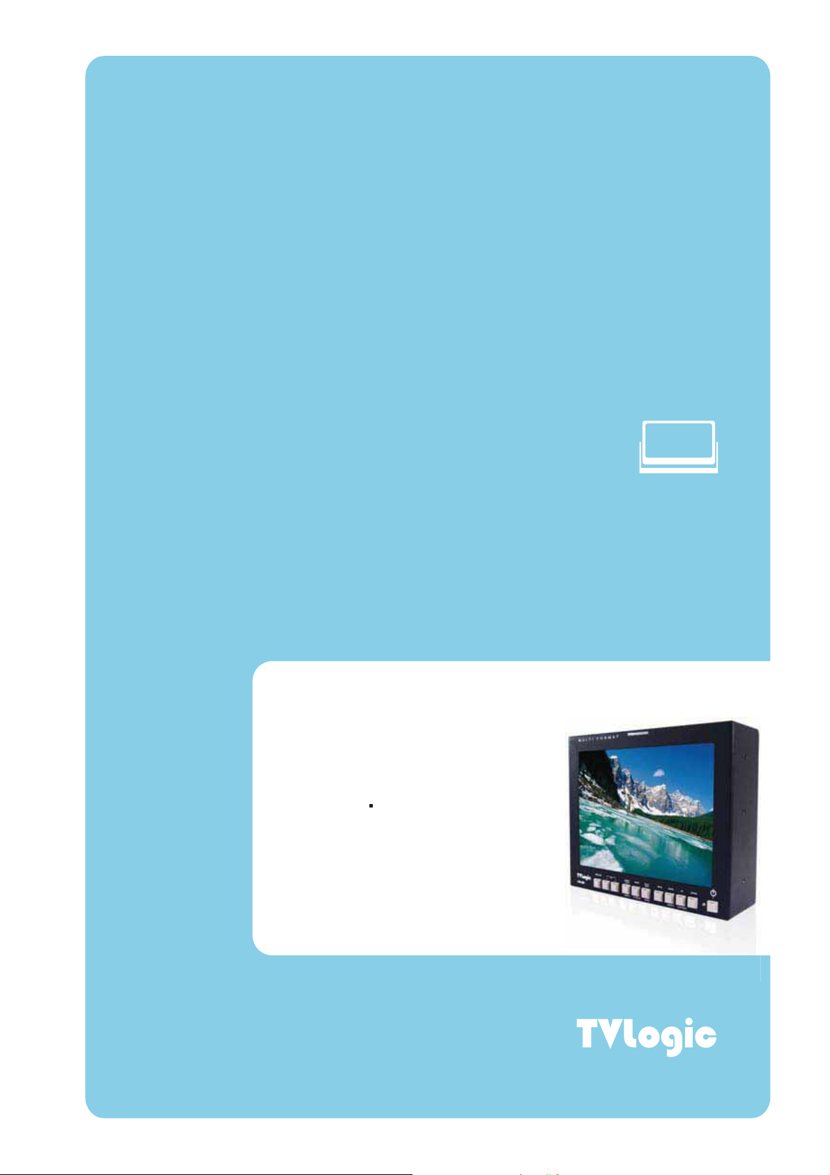
Multi-Format Broadcast
LCD Monitors
Operation Manual_v1.1
LVM-084
t
User’s Manual
Warning
· Always use set voltage.
- DC 12V 1.5A
· If liquid is spilled on or impacts this product, please disconnect
the product immediately and seek professional help before continued use.
· Keep unit disconnected during extended periods of disuse.
Keep unit in a well-ventilated place to prevent overheating.
·
Do not install the product near any heat-generating equipment.
·
Also, keep the product out of direct sunlight or dusty areas.
Only clean the product with a noncommercial, mild and neutral detergent.
·
When transporting the product, make use of its original packaging for safer carriage.
·
FCC (Federal Communications Commission)
This equipment has been tested and found to comply with the limits for class A digital device,
pursuant to part 15 of the FCC Rules. These limits are designed to provide reasonable
protection against harmful interface when the equipment is operated in a commercial
environment.
This equipment generates, uses, and can radiate radio frequency energy, and if not installed
and used in accordance with the instruction manual, may cause harmful interference to radio
communications. Operation of this equipment in a residential to correct the interference at
his own expense
Warning!! : Change or modifications not expressly approved by the manufacturer
!
responsible for compliance void the user’s authority to operate the equipment.
Disposal of Old Electrical & Electronic Equipment
(Applicable in the European Union and other European
countries with separate collection systems)
This symbol on the product or on its packing indicates that this product shall not be treated
as household waste. Instead it shall be handed over to the applicable collection point for
the recycling of electrical and electronic equipment. By ensuring this product is disposed
of correctly, you will help prevent potential negative consequence for the environment
human health, which could otherwise be caused by inappropriate waste handling of this
product. The recycling of materials will help to conserve natural resources.
02
and

Features
LVM Series units have the following features:
Compatible with varied SDI signals
The product is compatible with varied SDI Signals
- 480i, 576i, 720p, 1080i, 1080p, 1080psF (SDI A, B 2 channel compatible)
Compatible with varied analog signals
The product is compatible with varied analog signals
- Composite, S-Video, Component, RGB, etc.
All-in-one system
Slim and all-in-one type monitor that requires no additional accessories,
which provides optimized space utilization.
DC compatible
The product may be powered by normal AC source,
but also 12V DC source.
LVM-084
Remote control function
Remote-controlled simply with cable connection without additional
peripheral equipment attached to unit.
VGA function built-in
No other product can use common VGA Monitor.
Additional Features
Wide Viewing Angle, Reclocked Active Through OUT (SDI), VESA Mounting Standard,
400:1 contrast ratio, 400cd brightness, OSD user interface, rack mountable.
03

LVM-084
Name & Function of Each Part
<FRONT>
TALLY
SDI INPUT SELECT
UNDER SCAN / ASPECT
MARKER / H/V DELAY
BLUE ONLY / MONO
VGA IN
CVBS1 / Y / G / S-Y
CVBS2 / Pb / B
CVBS3 / Pr / R / S-C
SDI IN
SDI OUT
ANALOG INPUT
STAND BY
ENTER
UP / CONTRAST
DOWN / BRIGHT
MENU
<REAR>
REMOTE
COOLING FAN
FACTORY PGM
DC IN
04

<FRONT>
· ANALOG INPUT
Used to select desired ANALOG INPUT. A Sub Menu for each analog input
connected can be selected.
· SDI INPUT SELECT
Used to select SDI INPUT A or B.
· UNDER SCAN
Used to transfer from OVER SCAN mode to UNDER SCAN mode.
(Compatible up to SD 1:1 SCAN mode.)
· ASPECT
Used to change the monitor ratio on SD signal mode to 16:9.
· MARKER
Used to show MARKER on the screen. The type of marker at work may be selected
on the main menu.
LVM-084
· H/V DELAY
Used to observe horizontal sync and vertical sync simultaneously.
· BLUE ONLY / MONO
You may remove R(red) and G(green) from the input signal and play the screen only
with B(blue) signal. Button may be pressed twice to change the screen to MONO
mode. (This mode uses only luminance value.)
05

· MENU
Used when OSD menu is activated.
· DOWN/BRIGHT
Used to navigate menu during OSD menu activation. It may also be used to control
the BRIGHT value when the OSD menu is not active.
LVM-084
· UP/CONTRAST
Used to navigate the menu during OSD menu activation. It may also be used to
control the CONTRAST value when the OSD menu is not active.
· ENTER
Used to confirm a chosen value (or mode) during OSD menu activation or inactivation.
· STANDBY
Indicates power supply connection and current setting. The lamp is RED when unit is
connected to power supply and in standby mode and GREEN during system operation.
In case of sudden loss of power unit retains last setting.
· TALLY
LED indicating monitors current status
06

<REAR>
· REMOTE (RJ-45)
Connection for remote control of monitor.
· VGA IN / FACTORY PGM
Input connection for VGA mode and input connector for FACTORY PGM allowing for
firmware updates.
· CVBS1/Y/G/S-Y (BNC)
Signal input terminal used for COMPOSITE1, S-VIDEO Y, COMPONENT Y, RGB G signals.
· CVSBS2/Pb/B (BNC)
Signal input terminal used for COMPOSITE2, RGB B, COMPONENT Pb signals.
· CVSBS3/Pr/R/S-C (BNC)
Signal input terminal used for COMPOSITE3, S-VIDEO C, COMPONENT Pr, RGB R signals.
LVM-084
· SDI-IN (BNC)
SDI signal input terminals that provide A and B inputs.
· SDI-OUT (BNC)
SDI signal output terminal used for SDI output.
· DC 12V 1.5A IN (XLR, Male)
Used to supply DC power; 12V
· COOLING FAN
In order to prevent overheat, it affixed cooling fan.
· CHROMA/PHASE
Used to change the CHROMINANCE and PHASE values. Pressing the button once
will activate the CHROMA mode, pressing the button twice activates PHASE mode.
(PHASE may be used only with COMPOSITE and S-VIDEO on ANALOG mode.)
07
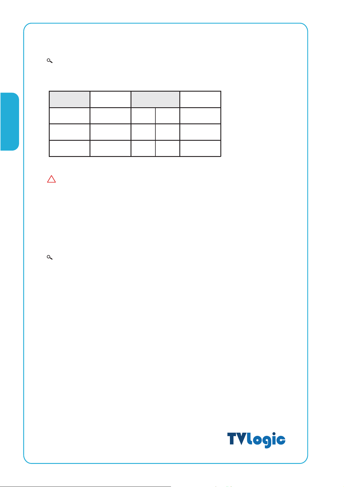
Information
Input VIDEO connection method
Connector Composite Component S-Video
1CVBS1YG Y
LVM-084
2
3CVBS3PrRC
Warning!!
!
Before using this unit make certain to connect the power supply before connecting a
signal to any of the inputs. The unit may not function properly if a signal is connected
before the power supply is connected. As an example: the unit will not function properly
when using an RCA-to-BNC (BNC-to-RCA) connection if the signal is connected to the
input before the unit is connected to the power supply.
Information
The UNDER SCAN and the MARKER button are including the ASPECT and H/V DELAY
function. When using, the UNDER SCAN and MARKER function pay attention become
first of all.
CVBS2 Pb B
No Con.
08
 Loading...