


TVLOGIC LQM-241W Schematic

Multi Format
LCD MONITOR
Service Manual
24” Multi Format LCD Monitor
LQM-241W
1

Caution
• Always use set voltage.
- AC 100 ~ 240V
- DC 24V [Tpy. 3.2A]
All operating instructions must be read and understood before the products is operated.
• These safety and operating instruction must be kept in safe place for future reference.
• All warning in this instruction must be observed closely and be followed.
• Do not use attachments not recommended by the manufacturer. Use of inadequate attachments
can result in accidents.
• If you are not sure of the type of power supply used in your home, consult your dealer or local
power company. For units designed to operate on batteries or another power source, refer to the
operating instruction.
• The power cord must be routed properly to prevent people from stepping on them or objects
from resting on them. Check the cords at the plugs and products.
• Do not overload DC outlets or extension cords. Overloading can cause fire or electric shock.
• Do not attempt to service the products yourself. Removing covers can expose you to high voltage
and other dangerous conditions. Request a qualified person to perform servicing.
• If any of the following conditions occurs, unplug the power cord from the DC outlet, and request a
qualified service person to perform repairs.
a. When the power cord or plug in damaged.
b. When a liquid was spilled on the products or when objects have fallen into the products.
c. When the products have been exposed to rain or water.
d. When the products have been dropped or damaged.
e. When the products display an abnormal condition. Any noticeable abnormality in the products
indicate that the products need servicing.
• Upon completion of service of repair work, request the service technician to perform safety checks
to ensure that the products is in proper operating condition.
• Keep the products away from direct rays of the Sun-light.
• Do not place the products on an unstable cart, stand, tripod or table. Placing the products on an
unstable base can cause the products to fall.
• When you disassemble the products, you lay smooth fabric so that the products keep away from
scratch.
• When you assemble the products, you set the electronic screwdriver’s torque as less than 2k and
screw each bolt and check if the cables connect properly. Setting the torque as more than 2k can
cause the case broken.
2
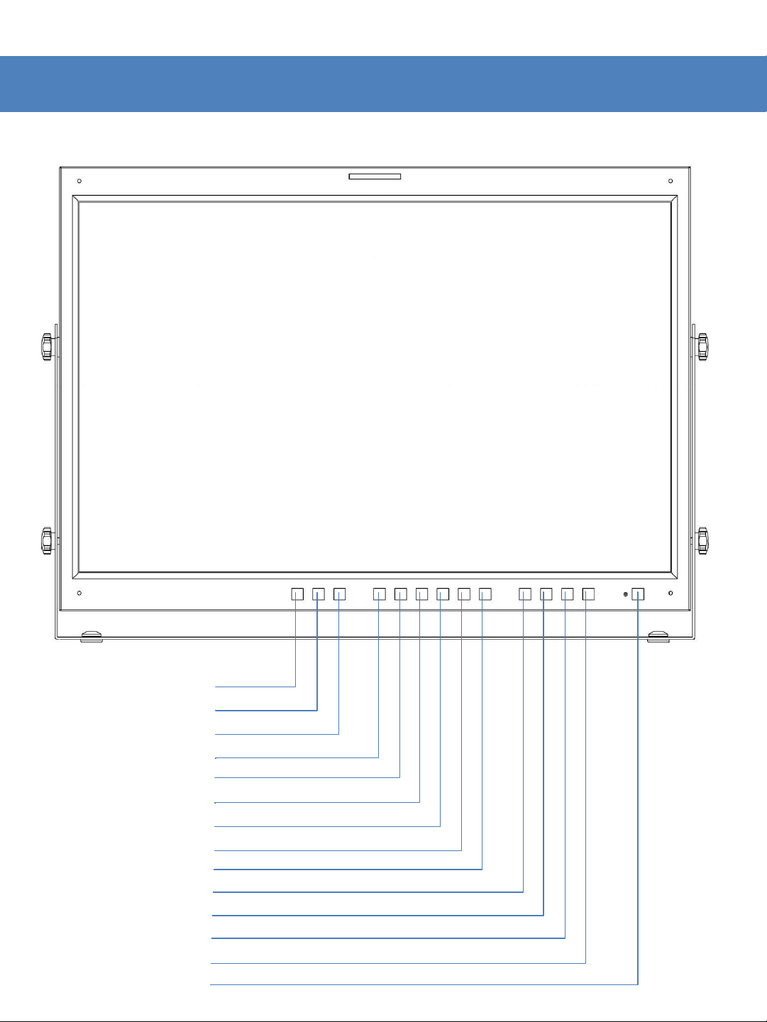
Part Name & Function
<FRONT>
ANALOG
MODE
QUAD
SCAN
ASPECT
MARKER
H/V DELAY
BLUE ONLY/MONO
CHROMA/PHASE/SCREEN SEL
MENU
DOWN/BRIGHT
UP/CONTRAST
ENTER/VOLUME
POWER
3
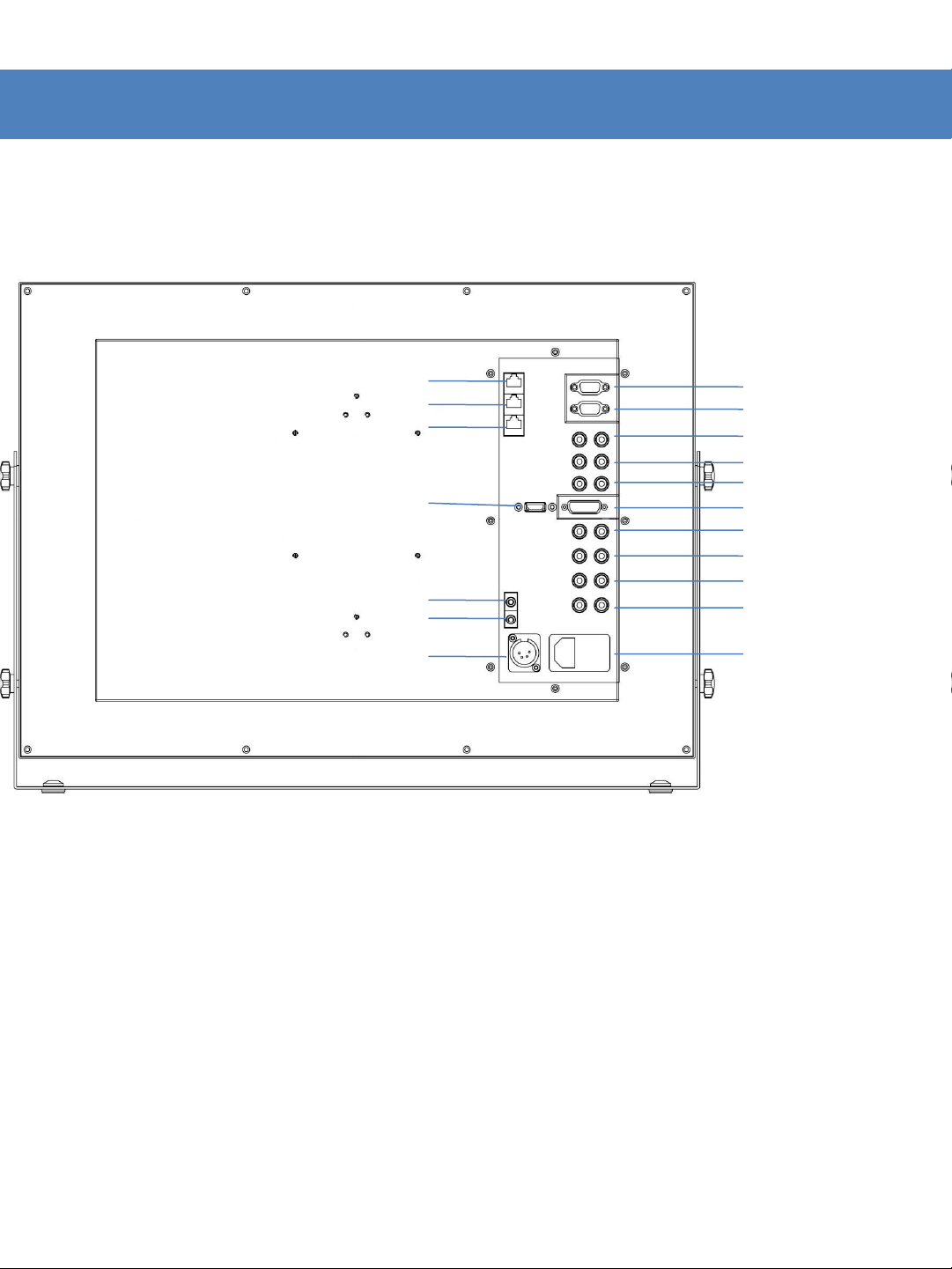
Part Name & Function
<REAR>
REMOTE
RS-422 IN
RS-422 OUT
HDMI(HDCP)
AUDIO IN
AUDIO OUT
DC 24V
Factory PGM1
Factory PGM2
CVBS1/G/Y/S-Y
CVBS2/B/Pb
CVBS3/R/Pr/S-C
DVI-I
SDI-A
SDI-B
SDI-C
SDI-D
Power & AC IN
4
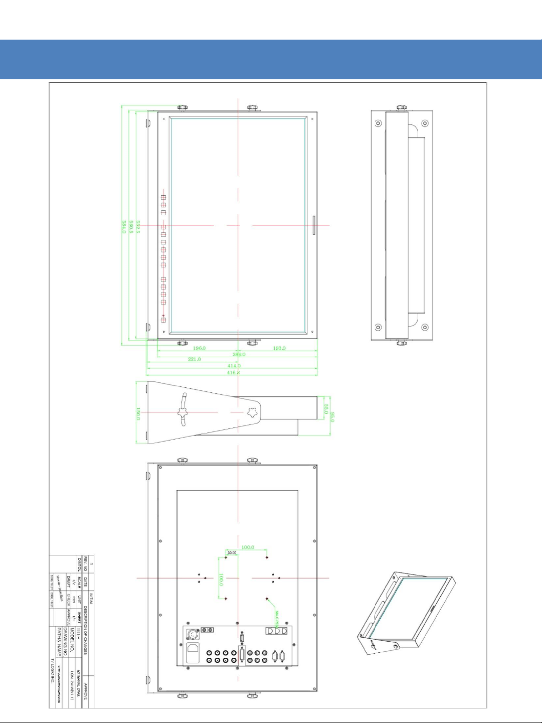
Drawing

Disassemble Drawing
Other Functions
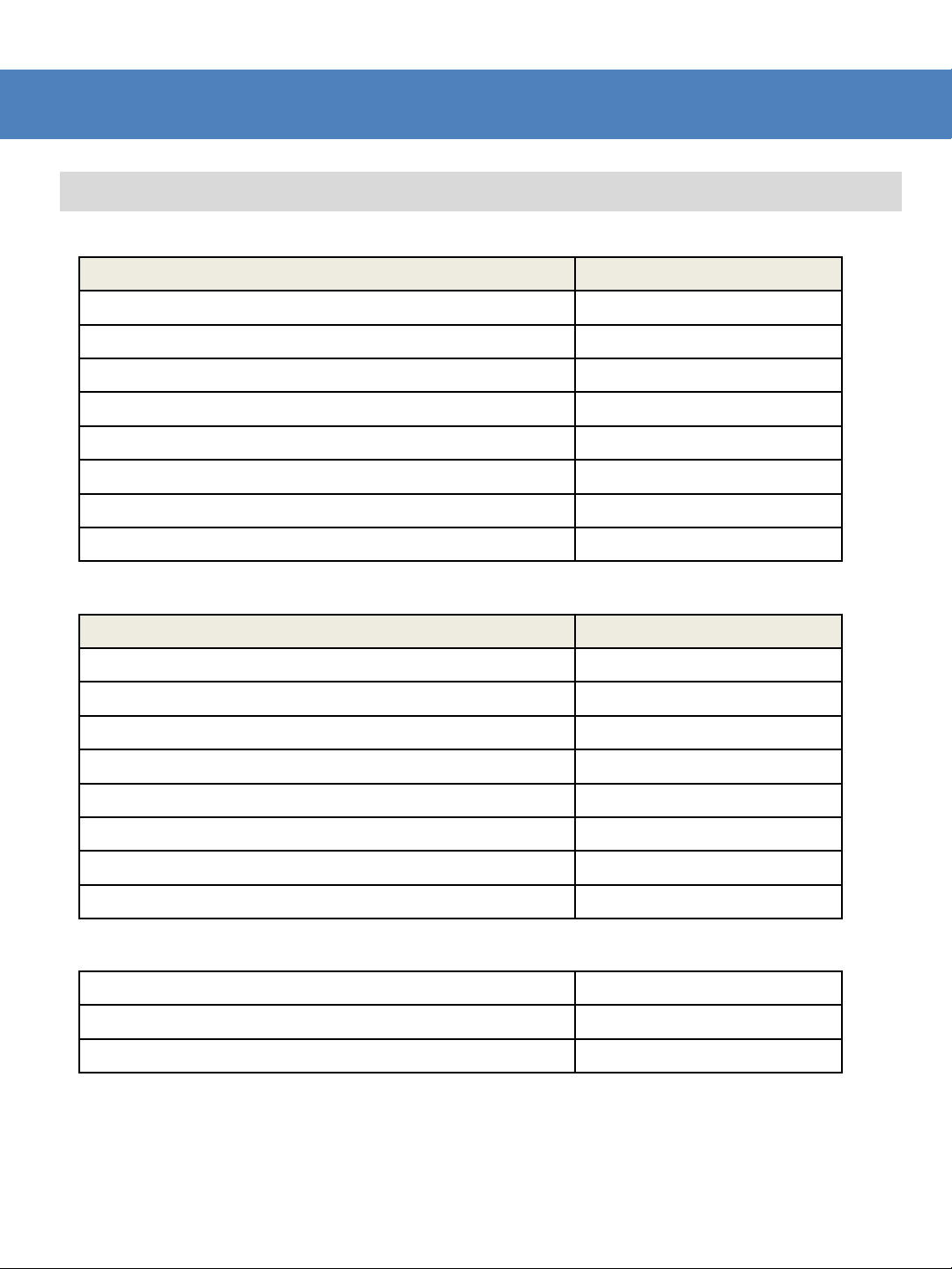
DVI ANALOG/DIGITAL Supportive Resolution
DVI ANALOG/DIGITAL Supportive Resolution
• DVI-ANALOG :
Resolution Frequency
640 × 480 60Hz, 75Hz
720 x 400 70Hz
800 × 600 60Hz, 72Hz, 75Hz
1024 × 768 60Hz, 70Hz, 75Hz
1366 x 768 60Hz/75Hz
1280 x 1024 60Hz/75Hz
1600 x 1200 60Hz
1920 x 1080 60 Hz
• DVI DIGITAL Graphic Mode :
• DVI DIGITAL Video Mode :
• DVI DIGITAL has two type : Graphic and Video.
• As in DVI ANALOG/DIGITAL mode, if it is not setting ZERO Scan on Scan mode, the screen might
be shown as an abnormal image.
• .If the setting on Aspect mode not Wide Screen, you can push ASPECT button then it shows Wide
Screen.
Resolution Frequency
640 × 480 60Hz, 75Hz
800 × 600 60Hz, 72Hz, 75Hz
1024 × 768 60Hz, 70Hz, 75Hz
1366 x 768 60Hz/75Hz
1280 x 1024 60Hz/75Hz
1600 x 1200 60Hz
1920 X 1080 60hZ
1920 x 1200 60 Hz
SMPTE-274M 1080i (60 / 59.94)
SMPTE-296M 720p (60 / 59.94)
SMPTE-125M 480i (59.94), 480p(59.94)
7

Specification
Input
1 x DVI
DVI
3 x BNC
Analog Input
4
SDI A/B/C/D Channel Input
1 x HDMI
HDMI Input
Output
3 x BNC
Analog Output
4 x BNC
SDI A/B/C/D Channel (Active Through Out)
Input Signal
Analog
Composite / S
HD
1.485Gbps
SD
270Mbps
DVI VESA/IBM Modes
HDMI
480i/480p/720p/1080i & VESA/IBM Modes
Analog Input Spec
Composite
1.0Vpp (With Sync)
S
1.0Vpp (Y With Sync), 0.286Vpp(C)
Component
1.0Vpp (Y With Sync), 0.7Vpp (
RGB 1.0Vpp (G With Sync), 0.7Vpp (B,R)
SDI Input Signal
Formats
SMPTE
1080i (60/59.94/50)
1080p (30/29.97/25/24/24sF/23.98/23.98sF)
SMPTE
720p (60/59.94/50)
SMPTE
1035i (60/59.94)
SMPTE
480i (59.94)
ITU
576i (50)
2K Format
2048 x 1080(23.98p/
Audio In
Embedded Audio / Analog Stereo (Phone Jack)
Audio Out
Analog Stereo (Phone Jack). Internal Speaker(Stereo)
LCD
Size 24” Resolution
1920 x 1200 (16:10)
Pixel Pitch
0.270(H) x 0.270(W) mm
Color 16.7M(true 8bit)
Viewing Angle
H : 176 degrees / V : 176 degrees
Luminance of
white
500
Contrast
1000:1
Display Area
518.4(H) x 324.0(V) mm
Power
24V DC / AC100~240V
Power Consumption (Approx.)
77 Watts(Max)
Operating Temperature
0
Storage Temperature
-
Main Body Dimensions (mm/inch)
Main Body Dimensions (With Stand)
Weight
Accessory
Option
LQM-241W
-I
x BNC
-SDI
-SDI
-Video
-274M
-296M
-260M
-125M
-R BT.656
-I(RGB) IN
-Video / Component / RGB
Pb,Pr)
psf, 24p/psf)
* 위 사양은 예고 없이 변경될 수 있습니다.
cd/㎡(Center)
°C to 40°C (32°F to 104°F)
20°C to 60°C (- 4°F to 140°F)
552.5 x 389 x 95 (21.73 x 15.31 x 3.74)
586 x 417 x 150 (23.07 x 16.41 x 5.90)
11Kg / 24.2 lb
AC Power cord, Manual
Carrying case, 19” Rack Mountable Kit, ND Filter
8
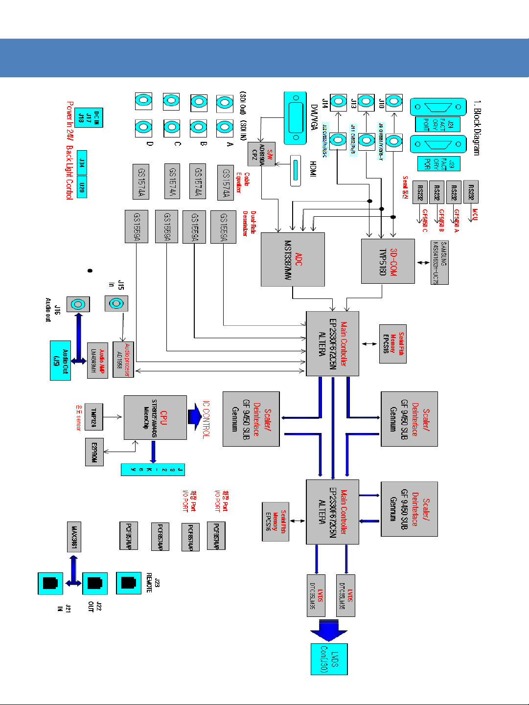
PCB Block Diagram
9

Circuit Operation Progress
• SDI (J1, J3, J5, J7) is sent to Main Controller(FPGA) through GS1574, GS1559
• ADC is available to deal with video signals relating to RGB/ YPbPr / HDMI / DVI and having Scaler
function.
• ADC sends the receiving signal to Main Controller(FPGA). Main Controller makes U5,U6(DTC35LM35)
and RGB 10bit from TTL 30bit dual ports output.
• U5, U6(DTC35LM35) is converter for LVDS signal.
• 3D-ROM handles with CVBS1~3.
• In order to use 3D-COM, SAMSUNG K4S641632H-UC75 is needed.
• HDMI, DVI, RGB, and YPbPr don’t get a signal at the same time.
• After changing Digital signal into Analog one, Audio AMP(LM4849) amplifies audio then puts out
Audio Out(J16).
•Main Controller gives data processing to Scaler/Deinterlace. Scaler/Deinterlace controls graphic
processing or screen output like Zoom in/out.
• Serial Flsh Memory is for saving Main Controller data.
• CPU controls all circuits.
• Key Control is controlled by CPU.
• Scaler/Deinterlace have 4 of DDR, save images, and load them whenever needed.
• PCF8574’s role is to extend I/O port.
• GPI Remote(J23) consist of parallel switch then control monitors the outside.
• GPI IN/OUT(J21, J22) controls protocol monitors or supports TSL protocol.
• RS232(J29) is for calibrating monitors using calibration tools.
• [Ethernet & USB]
- Easily update new program such as new function, debug, and etc..
• ~ AC IN
- 100 ~ 240V AC 50/60Hz
• DC 12V/24V IN
- 12V/24V DC(LVM-171W) or 24V DC(LVM-241W).
10
LCD
1.
A
B.
C
2.
A
B.
C
D
E.
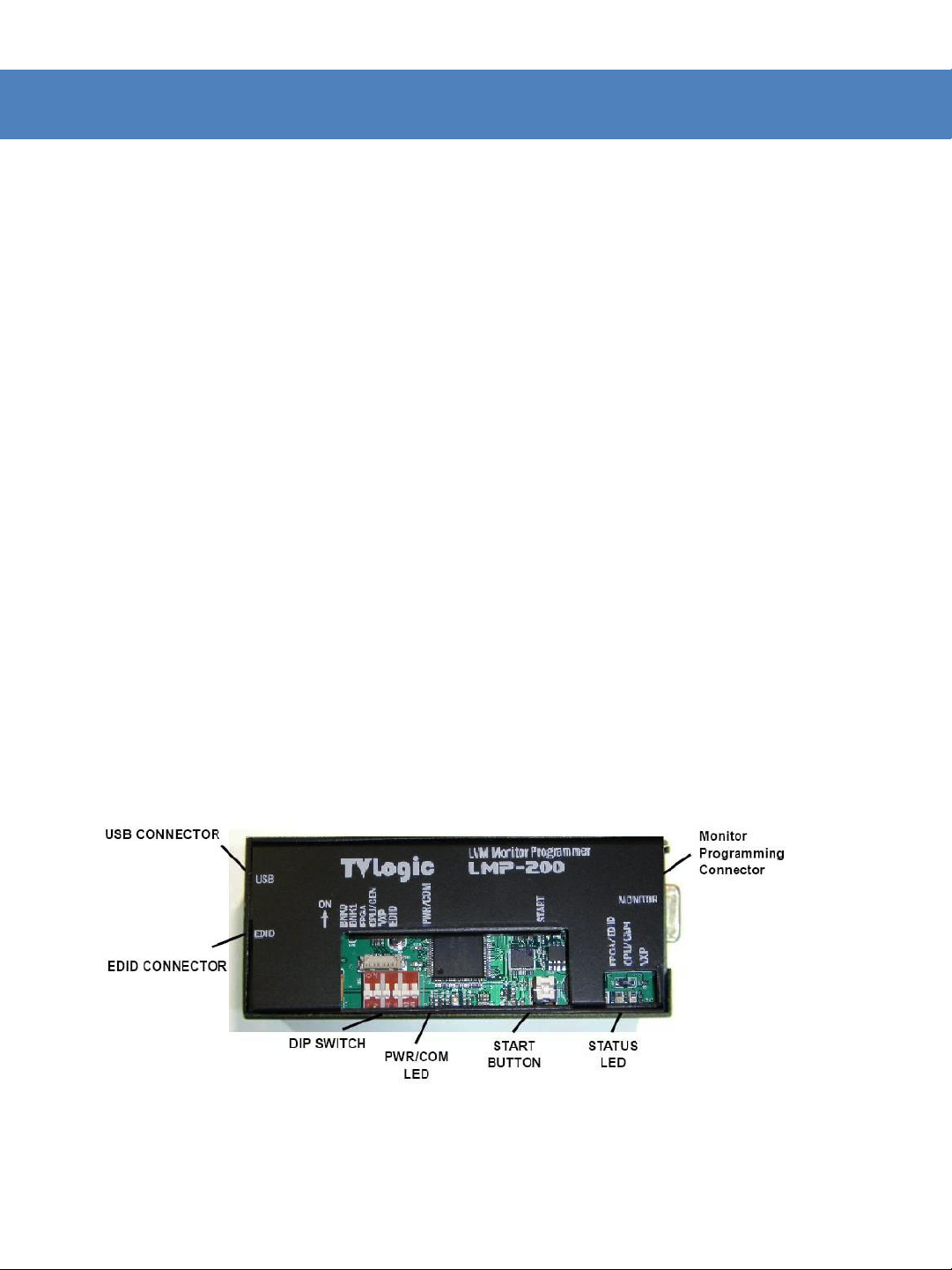
PROGRAM UPDATE – LMP200
programmer user manual (Model: LMP – 200)
Parts of Device
. LCD programmer (LMP – 200)
Program download cable (15 pin D-SUB)
. EDID download cable
Device Description
. USB CONNECTOR: USB port to connect to your PC
EDID: EDID cable port to connect to TVLogic monitor
. DIP S/W: Switch to select Bank # and Firmware upgrade
. PWR/COM LED: Power LED (also a communication status LED)
START BUTTON: Button to start a firmware update to TVLogic monitor
F. Monitor Programming Connector: Connector to connect to TVLogic monitor’s
Factory PGM port
11

3.
A.
200 and your PC with USB cable.
B.
PROGRAM UPDATE – LMP200
LCD Programmer Installation
Connect the LMP-
If device driver (“CyUSB.sys”) is installed to your PC, it will automatically
recognize the LMP-200. If not, Install the driver by running
“Add New Hardware” from your PC’s Control Panel.
12
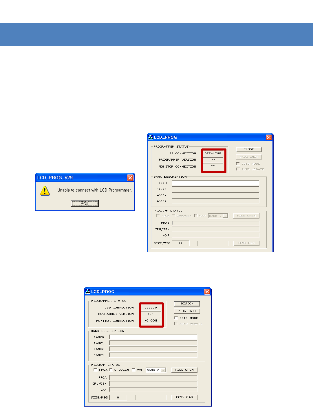
PROGRAM UPDATE – LMP200
4.
A
B.
C
How to Download Firmware to the LMP-200
. Connect the LMP-200 and your PC with USB cable.
Run “LCD-PROG.exe”. If your connection between the LMP-200 and
your PC is incorrect, a Message Window appears and the Programmer Status
appears as OFF-LINE.
. If you have a normal connection, the Programmer Status appears as USB 2.0
Connection and the Program Status box activates.
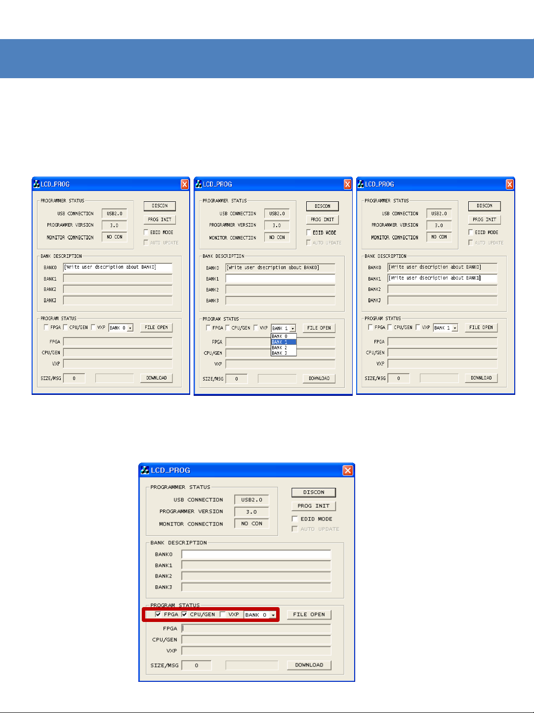
PROGRAM UPDATE – LMP200
D
. Select the BANK Number from BANK Selection Window in the
Program Status box (Available Banks for LMP-200 are BANK0~2 only).
Selecting the BANK number activates the BANK’s text box in the
BANK Description.
E. LQM-241W 는 FPGA와 CPU/GEN, VXP를 체크해 준다.