

T-Verter E2-2P5-*1, E2-1P5-H1, E2-1P2-H1, E2-2P2-*1, E2-202-H Operating Manual
...
E2 Adjustable Speed Driver
Microprocessor Controlled
IGBT Drive
Inverter Motor Speed Regulator
TAIAN
High Performance Adjustable Speed Micro Drives
Operating Manual
E2 Series
110V
220V
440V
0.2~0.75KW
( 0.53~1.6KVA )
0.2~2.2KW
( 0.53~4.0KVA )
0.75~2.2KW
( 1.7~4.0KVA )

Operations Manual
Table of Contents
Foreword......................................................................................1
Chapter 1 Safety Precautions
1. Precautions for Operation .......................................3
2. Environmental Precautions .....................................6
Chapter 2 Hardware Instruction and Installation
1. Operational Environment.........................................7
2. Sample Model No. Identification..............................8
3. Specifications ..........................................................9
4. Wiring ....................................................................15
5. Dimensions & Location of terminal block ..............18
Chapter 3 Software Index
1. Keypad Operating Instructions..............................27
2. Parameters List .....................................................28
3. Parameter Function Description............................29
4. Malfunction Indication and Countermeasure.........41
5. General Malfunction Examination Method ............44
Chapter 4 Trouble Shooting Procedure
1. Flow Chart………………………………………… 45
2. Maintenance Examination ……………………… 53
1. Foreword
To fully employ all functions of this AC Drive, and to ensure the safety for its users, please read
through this operations manual in detail. Should you have any further questions, please feel free to
contact your local distributor or regional representative.
※Please use Precaution with this product
The AC Drive is a power electronic device. For safety reasons, please read carefully those
paragraphs with “WARNING” or “CAUTION” symbols. They are important safety precautions to be
aware of while transporting, installation, operating or examining the AC drive. Please follow these
precautions to ensure your safety.
WARNING
CAUTION
Personnel injury may be resulted by improper operation.
The AC Drive or mechanical system may be damaged by improper operation.
z Do not touch the PCB or components on the PCB right after turning off the power before the
charging indicator went off.
z Do not attempt to wire circuitry while power is on. Do not attempt to examine the compon ents
and signals on the PCB while the inverter operating.
z Do not attempt to disassemble or modify internal circuitry, wiring, or components of the
inverter.
z The grounding terminal of the inverter must be grounded properly with 2 00V class type III
standard.
z This is a product of the restricted sales distribution class according to EN61800-3.
In a domestic environment this product may cause radio interference in which case the user
may be required to take adequate measures.
z Do not attempt to perform dielectric strength test to internal components of the inverter. There
are sensitive semiconductor-devices vulnerable to high voltage in the inverter.
z Do not connect the output terminals: T1 (U), T2 (V), and T3 (W) to AC power input
z The CMOS IC on the primary PCB of the inverter is vulnerable to static electrical charges. Do
not contact the primary PCB of the inverter.
WARNING
CAUTION
1

2. Examination before installation
Every inverter has been fully tested and examined before shipment. Please carry out the following
examination procedures after unpacking your AC inverter.
z Check to see if the mod el number of the AC inverter matches the model number of the AC
inverter that you ordered.
z Check to see whether any damage occurred to the AC inverter during shipment. Do not
connect the AC inverter to the power supply if there is any sign of damage.
Report this to a regional sale representative if you find any abnormal condition as mentioned
above.
2
Chapter 1: Safety Precaution
1. Precautions for operation
Before turning ON power
Choose the appropriate power source with correct voltage settings for the input voltage
specification of the AC inverter.
Special care must be taken while wiring the primar y circuitry panel. The L1 and L2
terminal must be connected to the input power source and must not be mistakenly
connected to T1, T2 or T3 out put terminals. This may damage the inverter when the
power is turned on.
CAUTION
WARNING
CAUTION
z Do not attempt to transport the inverter by the front of the cover. Securely hold the
inverter by the heat-sink mounting chass is to prevent the inverter from falling, this
may cause personnel injury or damage to the inverter itself.
z Install the inverter onto a firm metal base plate or another non-flammable type
material. Do not install the inverter onto or nearby any flammable material.
z An additional cooling fan may need to be installed if several inverters are installed
into one control panel. The inside temperature insi de an enclosed panel should be
below 40 degrees to avoid overheating.
z Turn off the power supply before proceeding to remove or perform any work on any
panel. Carry out installation procedures according to instructions given in order to
avoid a situation resulting in an operational malfunction.
z Suitable for use on a circuit capable of delivering not more than 5000 RMS
symmetrical amperes. 240 Volts maximum.
z This product is not provided with over speed protection.
z Only intended for use in a pollution degree 2 macro environment or equivalent
3

When power is applied
WARNING
z Do not attempt to install or remove input or out put connectors of inverter when the
power supply is turned on. Otherwise, the inverter may be damaged due to the
surge peak caused by the insertion or removal of power.
z When momentary power loss is longer than 2 seconds (the large of horse power,
the longer of time), the inverter does not have enough storage power to control the
circuit; Therefore, when power is regenerated, the operation of the inverter is
based on the setup of F_10 and the condition of external switch, this is considered
to be「restart」in the following paragraphs.
z When the momentary power loss is short, the inverter still has enough storage
power to control the circuit; therefore, when power is regenerated, the inverter will
automatically start operation again depends on the setup of F_23.
When restart the inverter, the operation of the inverter is based on the setup of
F_10 and the condition of external switch (FWD/REV button). Attention: the
restart operation is irrelevant with F_23/F_24.
(1) When F_10=0, the inverter will not start after restart.
(2) When F_10=1 and the external switch (FWD/REV button) is OFF, the inverter
will not start after restart.
(3) When F_10=1 and the external switch (FWD/REV button) is ON, the inverter
will start automatically after restart. Attention: Base on safety reason, please
turn off the external switch (FWD/REV button) after power loss to avoid
possible damage to the machine and the human body after sudden
regeneration of power.
4

Under Operation
Do not use a separate device to switch ON or OFF motor during operation. Otherwise,
the inverter may experience an over-current breakdown.
z Do not remove the front cover of the inverter when the power is ON to avoid
personnel injury caused by electrical shock.
z When the automatic restart function is enabled, the motor and machinery will be
restarted automat ica lly.
z Do not touch the heat-sink base during operation.
z The inverter can be easily operated from a low-speed to high-speed range. Please
reconfirm the operating range of motor and the machinery you are controlling.
z Do not examining the signals on the PCB of the inverter when it is under operation.
z All inverters are properly adjusted and set before delivery.
WARNING
WARNING
CAUTION
CAUTION
Do not proceed with disassemble or examination procedure before ensuring that the
power is off and the Power LED extinguished.
When performing an examination or maintenance
CAUTION
Inverter environment should be within temp: –10 OC ~ +40 OC, humidity under 95% RH
without condensing.
CAUTION
After the removal of shield sticker, the environment temperature should be
within –10
inverter should be free from water dripping or metal dust.
O
C ~ +50OC and humidity under 95% RH without conden sing. Besides, the
5

K
h
igh
2. Precautions of operation environment
oil
Avoid any direct sunlight
Keep away from
corrosive gas or liquid
Keep away from salty
environments
Keep away from rain or
where dripping water may
get into the inverter
Keep away from oil
grease and gas
Avoid metal dust and
dusty environments
Avoid massive vibration
Avoid excessive direct heat
eep away from
electrical-magnetic waves
or ultra-high waves.
Keep away from
radioactive matter
6
Avoid where
environmental
temperatures are too high
Keep away from
flammable material
Chapter 2: Hardware Instructions and Installation
1. Operational Environment
The installation site of the inverter is very important. It relates directly to the functionality and the life
span of your inverter. Please carefully choose the installation site to meet the following
requirements:
z Mount the unit vertically
z Environment temperature: -10
z Avoid placing close to any heating equipment
z Avoid water dripping or humid environment
z Avoid direct sunlight
z Avoid oil or salty corrosive gas
z Avoid contacting corrosive liquid or gas
z Prevent foreign dusts, flocks, or metal scraps from entering interior
z Avoid electric-magnetic interference (soldering or power machinery)
z Avoid vibration, if vibration cannot be avoided, an anti-rattle mounting device should be
installed to reduce vibration.
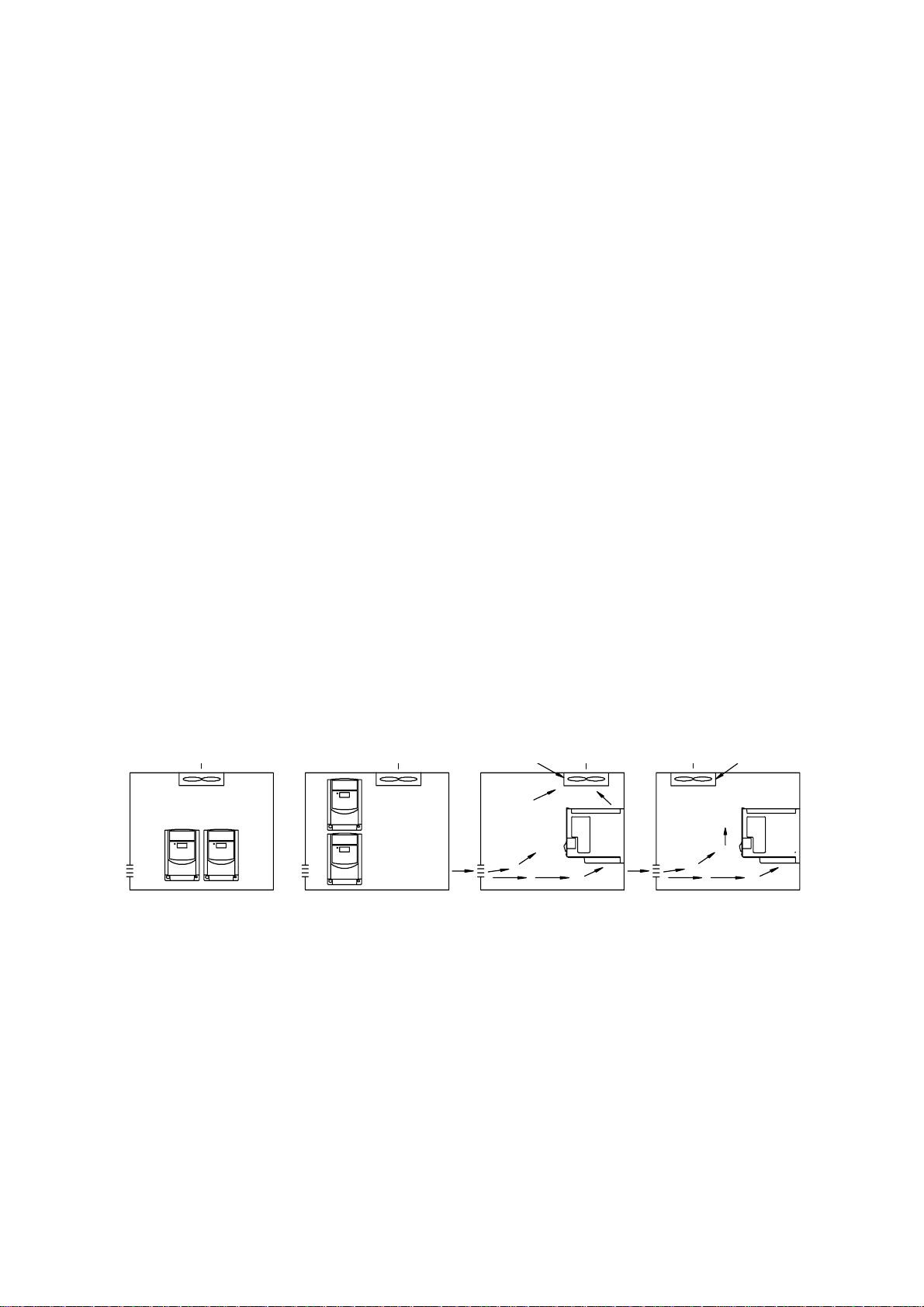
z If the inverter is installed in an enclosed control panel, please remove the shield sticker located
at the top of the inverter. This will allow additional airflow and cooling.
Correct Alignment Wrong Alignment Correct Alignment Wrong Alignment
z For proper Installation of the inverter you must place the fro nt side of the inverter facing front
and the top of the inverter in the up direction for better heat dissipation.
z Installation must be compliant to the following requirements.
External Fan Placement needs to be over the top of the inverter
O
C ~ +40OC (without shield sticker: -10OC ~ +50OC)
7
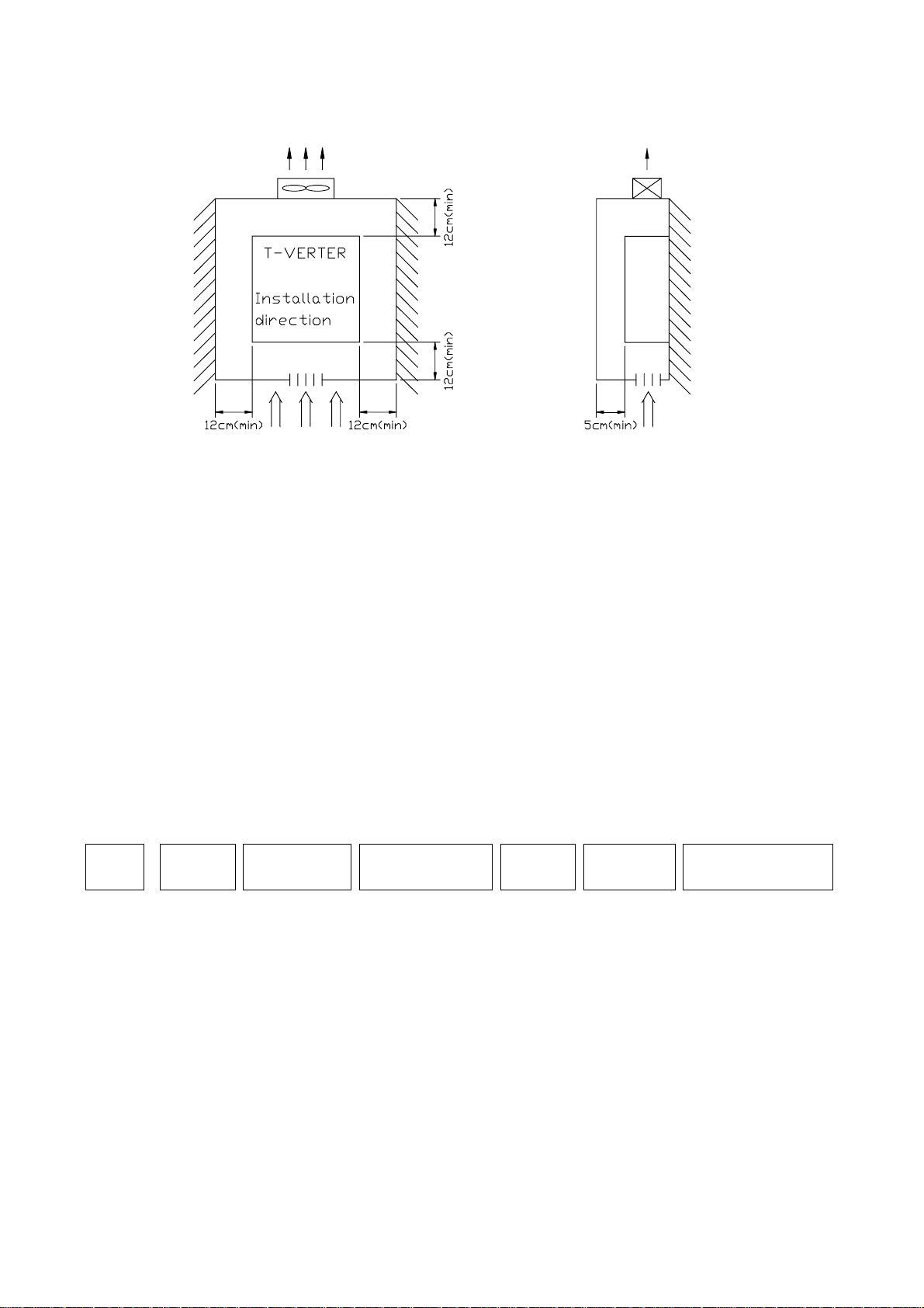
Note: Maximum temperature in the enclosure 50 ℃
Ventilation & Installation
Direction
Front View
2. Sample Model No. Identification
Inverter Model ⇓ MODEL: E2-201-M1F
Input Power Rating ⇓ I/P: AC 1PH 200 ~ 240V 50/60 Hz
Output Rating ⇓ O/P: AC 3PH 0 ~ 240V 1 Hp 4.2 Amps
E2 - 2 01 - M 1 F N4
Series Power
Voltage
1 : 110V
2 : 220V
4 : 440V
Horse Power
Rated
P2 : 0.25 Hp
P5 : 0.5 Hp
01 : 1 Hp
02 : 2 Hp
03 : 3 Hp
Model
Type
M : CPU Version
V1.6
H : CPU Version
V1.9 or above
Power
Supply
1 : Single
Phase
3 : Three
Phase
Blank :
Single or
Three
Phase
Filter
Option
F :
with filter
Blank :
without filter
Enclosure
Type
N4S :
meet
IP65/NEMA4
Standard with
Switch
N4 :
meet
IP65/NEMA4
Standard without
Switch
Blank : IP20
8

3.Specification:
Basic specification:
Model : E2-
Suitable Motor Power R ating (KW) 0.2 0.4 0.75
Rated
Input Voltage Max. Single phase 100-120V (+10%, -15%), 50 / 60Hz (+/-5%)
Output Voltage Max. Three phases 200-240V (Proportional to input voltage)
Dimension W*H*D (mm) 72*132*118
EMC Specification
Motor (HP)
Output Current (A) 1.4 2.3 4.2
Capacity (KVA) 0.53 0.88 1.6
Weight (Kg ) 0.7 0.72 0.8
1P2-H1x
1/4 1/2 1
1P5-H1x 101
Without Filter
Model: E2-
Suitable Motor Power Rating (KW) 0.2 0.4 0.75 1.5 2.2
Rated
Input Voltage Max. Single/Three phases 200-240V (+10%, -15%), 50 / 60Hz (+/-5%)
Output Voltage Max. Three phases 200-240V (Proportional to input voltage)
Dimension W*H*D (mm) 72*132*118 118*143*172
EMC Specification
Motor (HP)
Output Current (A) 1.4 2.3 4.2 7.5 10.5
Capacity (KVA) 0.53 0.88 1.6 2.9 4.0
Weight (Kg) 0.76 0.77 0.8 1.66 1.76
2P2-x1xx
0.25 0.5 1 2 3
2P5-x1xx 201-x1xx
Class A (Single Phase Filter built in)
202-Hxxx
203-Hxxx
Model : E2- 401-H3xx
Suitable Motor Power R ating (KW) 0.75 1.5 2.2
Rated
Input Voltage Max. Three phases 380-480V (+10%, -15%), 50 / 60Hz (+/-5%)
Output Voltage Max. Three phases 380-480V (Proportional to input voltage)
Dimension W*H*D (mm) 118*143*172
EMC Specification
Motor (HP)
Output Current (A) 2.3 3.8 5.2
Capacity (KVA) 1.7 2.9 4.0
Weight (Kg ) 1.6 1.62 1.68
1 2 3
Class A (Three Phases Filter built in)
402-H3xx
403-H3xx
9

Functional specification:
Item Specification
Input Signal Type PNP type (SOURCE) input (External 24VDC Input is allowed)
Control Method Sinusoidal wave PWM control
Freq.
Control
General
Control
Display Three digital LED display frequency / inverter parameter / fault
Operating temperature -10 ~ +40OC (without shield sticker: -10OC ~ +50OC)
Humidity 0~95% RH non-condensing.
Vibration Under 1 G (9.8 m/s2)
EMC specification EN5008-1, EN5008-2, EN50082-1, EN50082-2, EN50178
UL UL508C
Protection
Function
Installation Mounting screw or DIN rail (Option).
Note: *1: New function for CPU version v1.9 and above.
Freq. Range 1~200 Hz*1
Resolution Setting Digital: 0.1 Hz (1 ~ 99.9 Hz); 1 Hz (100 ~ 200 Hz)
Analog: 1Hz/ 60 Hz
Keyboard Setting
External Signal Setting 0~10V, 4 ~ 20mA, 0 ~ 20mA
Other function Frequency upper and lower limit
Carrier frequency 4~16KHz*2
Accelerate/Decelerate time 0.1~ 999 Sec
V/F Pattern 6 Patterns
Torque control Torque boost level adjustable (manual torque boost)
Multi-Functional input 2 point, to be used as multi-speed 1(Sp.1) / multi-speed 2(Sp.2) *1/
Multi-Functional output 1a Relay terminal, to be setup as Fault / Running / Frequency.
Braking Torque 1P2~101/2P2~201:About 20%
Other function Decelerate or free run stop, Auto reset, DC braking frequency /
Overload protection 150% for 1 min.
Over-voltage DC voltage > 410V(100/200 series); DC voltage > 800V(400 series)
Under voltage DC voltage < 200V(100/200 series); DC voltage < 400V(400 series)
Momentary Power-loss 0 ~ 2 sec: The inverter can be restarted using speed search
Stall Prevention During Acceleration / Deceleration/ Constant speed
Output Short-circuit Electronic circuitry protection
Grounding fault Electronic circuitry protection
Other function Heat sink overheat protection, Current limit
Directly setup by ▲▼ buttons.
Jog / External emergency stop / External bb / Reset
202/203/401/402/403: 20%~100%, built-in braking transistor
Voltage / Time can be setup by constants.
record / program version.
feature.
*2: Carrier frequency range: CPU version v1.6 is 4~8kHz.
CPU version v1.9 and above are 4~16kHz.
10
Suitable optional and Wiring Specification
Molded-Case Circuit Breaker / Magnetic Contact
z Warrantee does not apply to damage caused by the following situations:
(1) Damage to the inverter caused by the lack of appropriate molded-case circuit breaker or
when a circuit breaker with too large of capacity is installed between the power supply and
the inverter.
(2) Damage to the inverter caused by the magnetic contact, phase advancing capacitor, or
surge-protector installed between the inverter and the motor.
Model Type 1P2/1P5/2P2/2P5 101/201/202 203 401/402/403
Molded-case circuit breaker 15A 20A 30A 15A
Primary Circuit Terminal (TM1)
L1 L2
T1
T2
Signal Terminal (TM2)
1~11
Use copper conductors only size field wiring based on 80 degrees C wire only.
T3
Wire dimension
(#14AWG) 2.0mm
Terminal screw M3
Wire dimension 0.75mm
Wire dimension
(#14AWG)
2
Terminal screw
Wire dimension
2.0m m
2
M3/M4
2
(#18 AWG), Terminal screw M3
3.5mm
Terminal screw
M4
Wire dimension
2
Terminal screw
3.5mm2
M4
z Please utilize three-phase squirrel-cage induction motor with appropriate capacity.
z If the inverter is used to drive more than one motor, the total capacity must be smaller
than the capacity of the inverter. Additional thermal overloa d relays must be installed in
front of each motor. Use the Fn_18 at 1.0 times of the rated value specified on the motor
nameplate at 50Hz, 1.1 times of the ra te d val ue spe ci fi ed on the motor nam epl at e a t 60Hz.
z Do not install phase advancing capacitors, LC, or RC component between the inverter and
the motor.
11

A
Application and precautions of Peripherals
From the Power Source:
z Apply the power source at the correct rated voltage to prevent from damaging the inverter.
Power Disconnect or Circuit breaker must be installed between the AC power supply and the
z
inverter.
Molded-case circuit breaker:
z Utilize an appropriate circuit breaker that’s suitable for the rated voltage and current ratings of the
inverter to switch ON/OFF the power supply to the inverter and as additional protection for the
inverter.
z Do not operate the circuit breaker to switch ON or OFF the inverter. The circuit breaker should be
used only to supply input power and should not be used for operational sequence.
Leakage circuit breaker:
z An earth leakage circuit breaker should be added to prevent false operation cause by leakage
current and to ensure personnel safety.
Magnetic Contact:
z The Magnetic Contact can be omitted at ordinary operation. To utilize external control, automatic
restart, or breaking controller the magnetic contact must be added at the primary side.
z Do not operate the magnetic contact to switch ON or OFF the inverter.
Power improvement AC Reactor:
z If large capacity power source is applied (over 600KVA), additional AC reactor may be added to
improve power factor.
Inverter:
z Power supply input termi nals L1 and L2 are not differentiated on phase sequence. They can
be arbitrarily connected. Their connection may be interchanged.
z Output terminal T1, T2, and T3 should be connected to the U, V, and W terminals of the motor
respectively. If motor turns in opposite direction of the inverter command, simply exchanging two of
the three wire connections will correct this problem.
z Output terminal T1, T2, and T3 must not be connected to power source to prevent from damaging
the inverter.
z Grounding terminal Properly ground the grounding terminal in compliance to 200V class type
three grounding. (The 400V class type is special grounding.)
12
External wiring should be carried out in accordance with following requirement. Check and reassure the
wiring is correct after the wiring is complete.
(Do not utilize the control circuitry buzzer to check the wiring.)
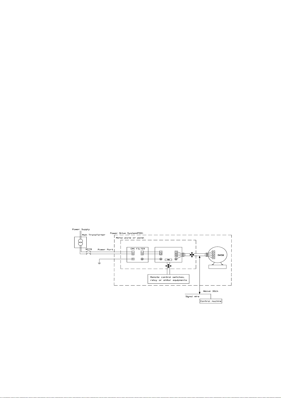
EMI connections:
It is very important that the connections between the inverter, the shielded motor cable, and the EMI
filters are tested as follows.
z Use a metal grounding plate and place the frequency inverter and the EMI filter on the plate.
z Use a shielded motor cable with 4 connectors (U, V, W, & Earth), don’t use the shielding as safety
earth (shield is high frequency earth)
z Remove any paint around the two metal coupling nut holes. So that the metal coupling nuts (and
the shielding) make contact with the frequency inverter and the motor.
z Don't solder a conductor to the shielding.
z Use a metal clamp to connect the shielding from the motor cable with the metal grounding plate.
Now there is a perfect high frequency earth connection between frequency inverter, grounding
plate and EMI filter.
z Keep the distance between the frequency inverter and EMI filter as short as possible (< 30cm) if
longer use a shielded cable with a metal coupling nut and a metal clamp to connect the shielded
cable to the frequency inverter and metal grounding plate.
z The only earth connection between the LISN and the test plate should be via the EMI filter.
z Use a motor which equals the power rating or below of the inverter rating.
Install a noise filter for inverter onto the output side of the primary circuitry can suppress
z
conducting noise.
Class B:
13
Drive
Class A:
Drive
When the distance between the inverter and motor is longer than 100 meters, cable wire should be
carefully chosen to reduce the wiring resistance below 3% and the voltage drop (V) = √3 x Wire
resistance (Ω/km) x wire length (m) x current x 10
-3
(B) Control circuitry wiring must be separated terminated and away from the primary power circuitry
and other high-voltage or large-current power lines to avoid noise interference.
z To reduce the noise interference and avoid possible operational problems, shielded twisted pair
cable should be used to wire the control circuitry. Please refer to following diagram. Connect the
shielding wire onto the grounding terminal. Only connect one end of the shield.
Wiring distance must be under 50m.
To Inverter terminal
Connect Shield
Connect to system grounding terminal
Shielding
Glove
Wrapped with
insulating tape
To control machine
Do not connect the shielding
wire at this end
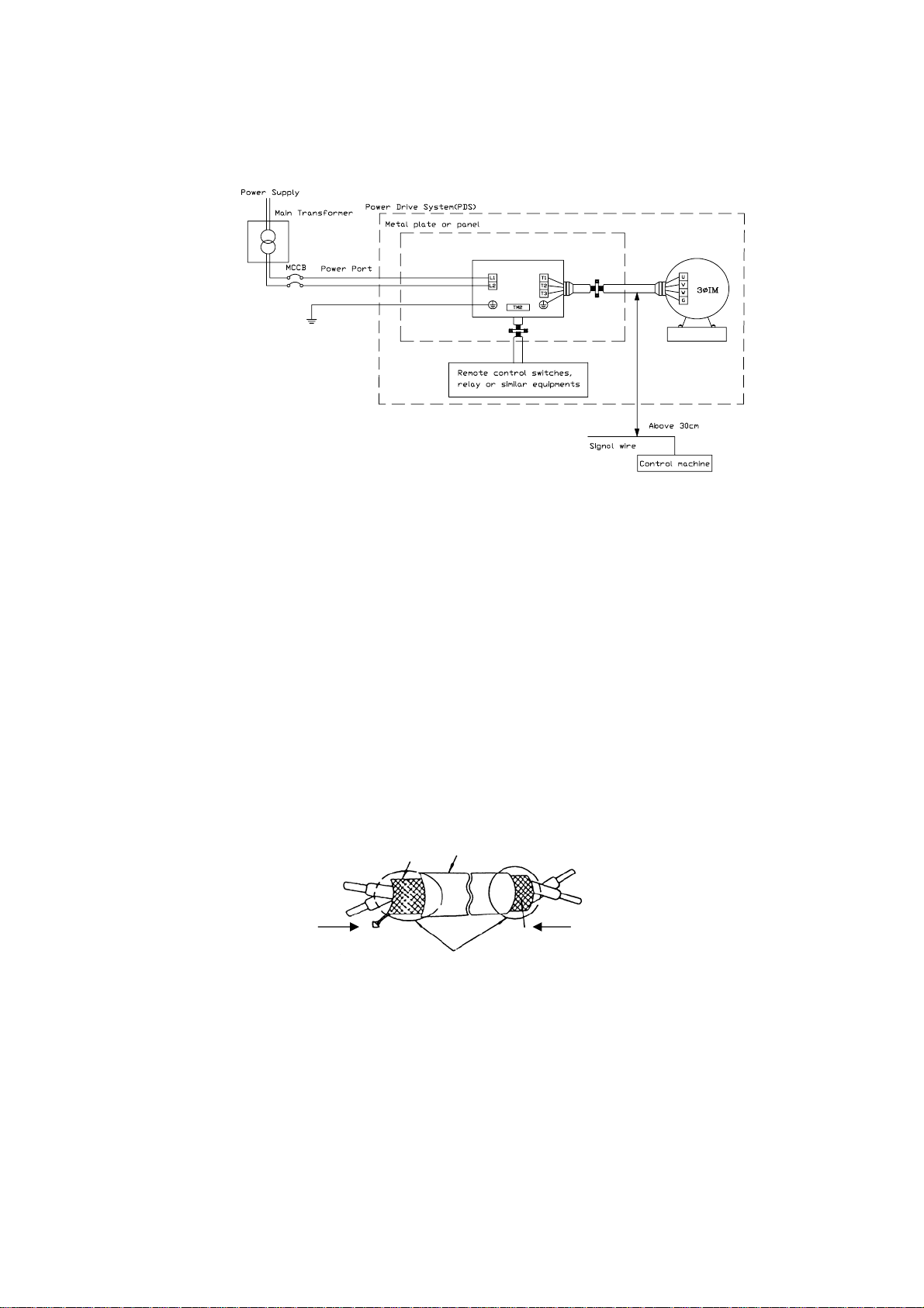
(C) The grounding terminal of the inverter must be correctly grounded in compliance with 200V
class type three grounding.
z Grounding wire should be wired in accordance to electrical equipment (AWG) wi th the length
of the grounding wire as short as possible.
z The g rounding wire of the inverter must not be grounded together with other large current
14
loads (such as soldering machines or large current motors). They should be grounded
)
}
3
4
6
7
5
{
M
p
separately.
z Grounding circuitry must not be formed when grounding several inverters together.
(a) good (b) good (c) not good
(D) Wire spec ification, apply appropriate wire with correct diameter for primary power circuitry and
control circuitry in accordance with electricity regulations.
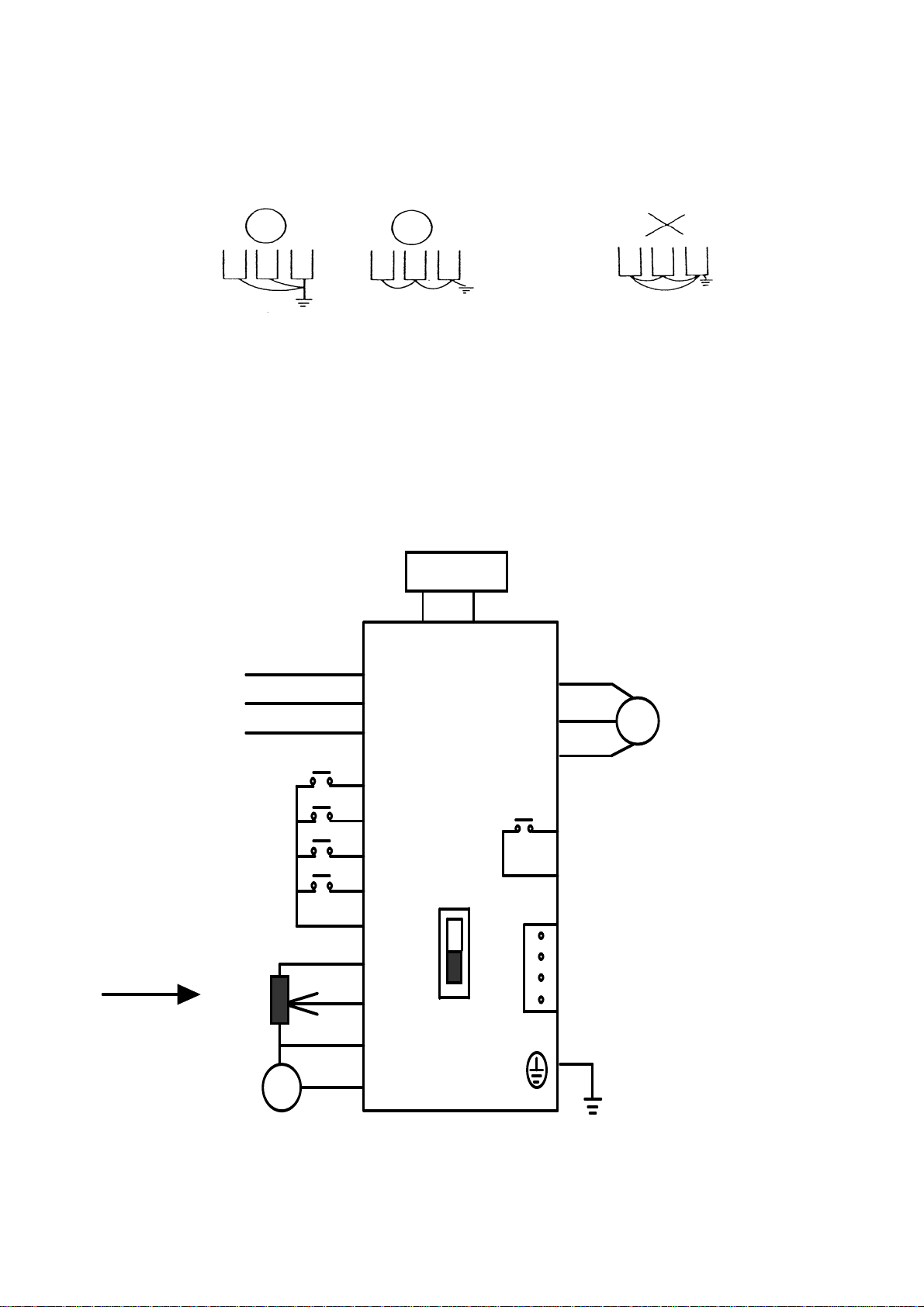
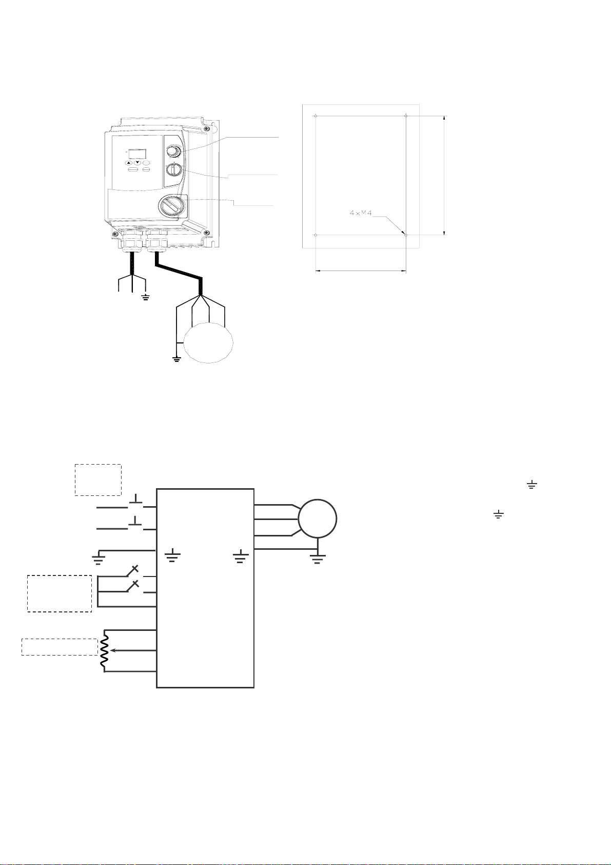
Wiring Diagram
*(note)B raking
Re s is te r ( Opti o n
AC Inp u t
Multi-Function
Input s
eed Pot
S
10kΩ
F
0~10V
L1 (L)
L2
L3 (N)
FWD
REV
SP1
RST
12V
8
+10V
9
MVI
10
(0~10V/0~20/4~20mA)
0V(FM–)
11
FM+
P R
(U)T1
(V)T2
(W)T3
1
2
SW1
CON2
1
2
3
IM
Trip Relay
Te s t P oin ts
Grounding
Wire Terminations to the Inverter must be made with either UL listed field wiring lugs or UL listed crimp
15
type ring terminals.
6
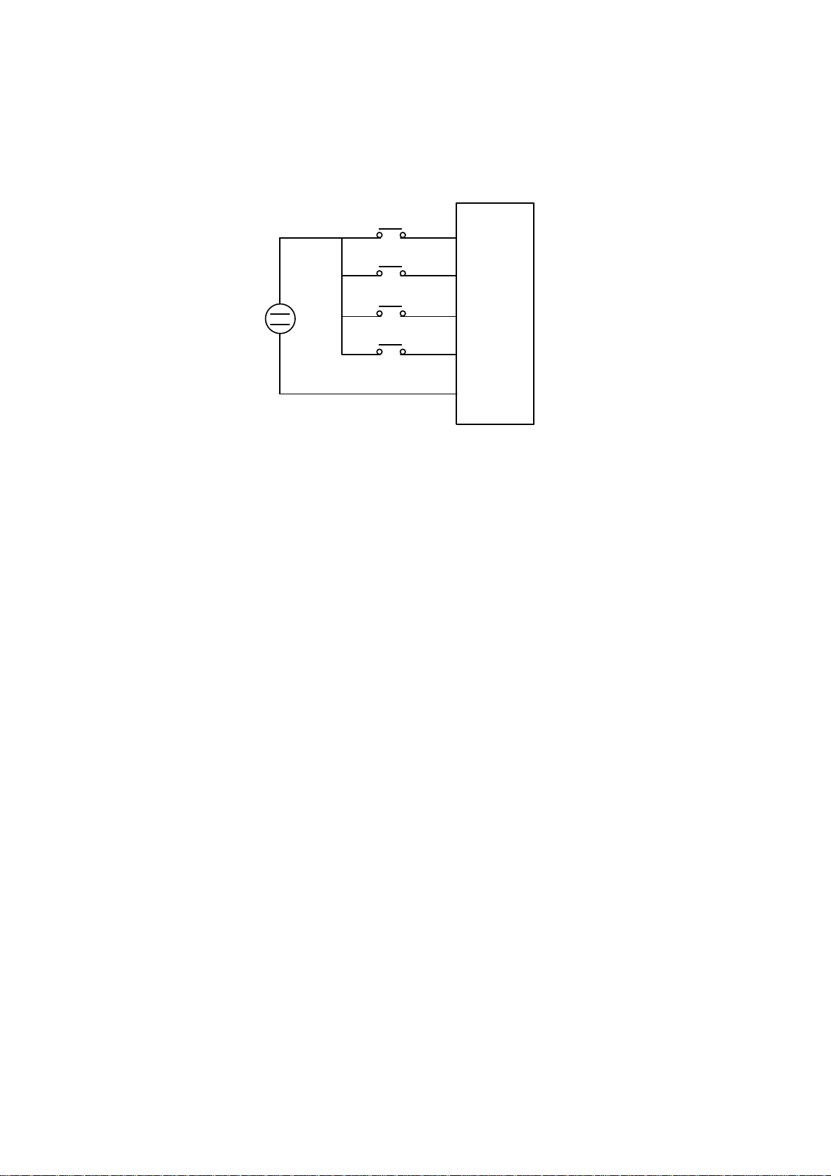
Note: Only for 202/203/401/402/403.
(External 24V supply)
z
3
4
TM2
FWD
REV
+
24V
–
SP1
7
RST
10
0V
16
Inverter terminal descriptions
A
Primary Circuitry Te rminal Block (TM1) des c riptions
Terminal Symbol Function Description
L1/L (R)
L2 (S)
L3/N (T)
P
R
T1 (U)
T2 (V)
T3 (W)
Primary power source input to Drive
Single phase: L1/L2 or L/N
Three phase: L1/L2/L3
Extermal braking resistor terminal (Only for E2-202/203/401/402/403)
Inverter output to Motor
Tightening torque for TM1 is 1 LBS-FT or 12 LBS-IN (1P2/1P5/2P2/2P5/201).
Tightening torque for TM1 is 1.3 LBS-FT or 16 LBS-IN (202/203/401/402/403).
* Wire voltage rating must be a minimum of 300V(200V series)/600V(400V series)
Control Circuitry Terminal Block ( T M2) descrip t i on
Terminal Symbol Function Description
1
2
TRIP
RELAY
Fault relay output terminal ﹠Multi function output terminal (refer to F_21)
Connection point rated capacity 250VAC/1A (30VDC / 1A)
3 FWD (FW)
4 REV (RE)
5 + 12V(12) Common point of terminal 3 / 4 / 6 / 7
6 SP1(SP)
7 RESET(RS)
8 +10V Power terminal for potentiometer ( Pin 3 )
9
0V(FM -)
10
11 FM+
Operation control terminals (refer to F_03)
Multifunction input terminals (refer to F_19)
Analog input wire
Wiper
Analog common point
Analog output positive
connection point
Analog frequency signal input terminal ( Pin 2 of
potentiometer or positive terminal of 0~10V / 4~20mA /
0~20mA)
nalog signal common point ( Pin 1 of potentiometer or
negative terminal of 0~10V / 4~20mA / 0~20mA )
Analog frequency signal output terminal
Output terminal signal is 0 ~ 10VDC/Fn6
Tightening torque for TM2 is 0.42 LBS-FT or 5.03 LBS-IN.
* Wire voltage rating must be a minimum of 300V
* Control wiring should not run in the same conduit or raceway with power or motor wiring
* Single Input and Output Terminals (TM2) Ratings are ALL Class 2
17
SW1 function description
SWITCH 1 External signal type
0~20mA analog signal (When F_11 is set to 1)
4~20mA analog signal (When F_11 is set to 2)
0~10 VDC analog signal (When F_11 is set to 1)
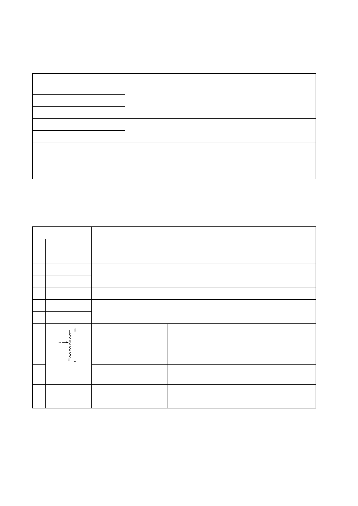
Dimensions & Location of terminal block
E2-1P2/1P5/101/2P2/2P5/201:
See NOTE
DEMESIONS MODEL
E2-1P2/1P5/101/2P2/2P5/201 132 116 130 8.2 118 61 72
NOTE: For safety reason, we strongly recommend
users to remove the M4 grounding screw,
Unit: mm
A B C D E F G
then screw the enclosed “metal frame
grounding terminal” on the same location to
make a grounding bar to ensure good earth
protection.
18
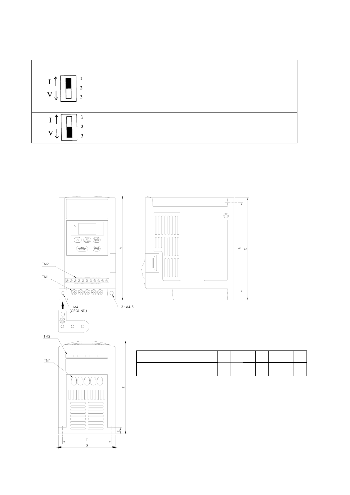
E2-202/203/401/402/403:
See NOTE of Page 18
MODEL
E2-202/203/401/402/403
MODEL
E2-202/203/401/402/403
LEN G TH
LEN G TH
U n it:m m
A
143.1127.5B140
171.7E108F118
CD
G
8.0
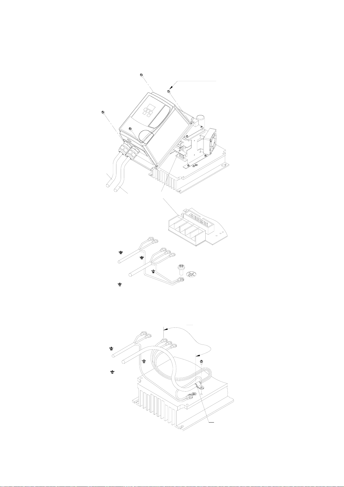
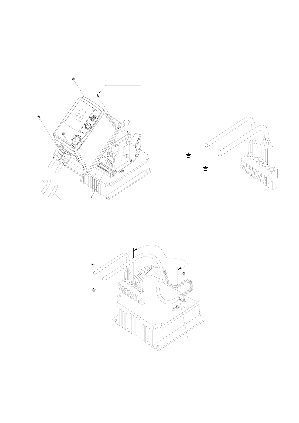
Dimensions & Installation of class B Filter
19
M4 x14L
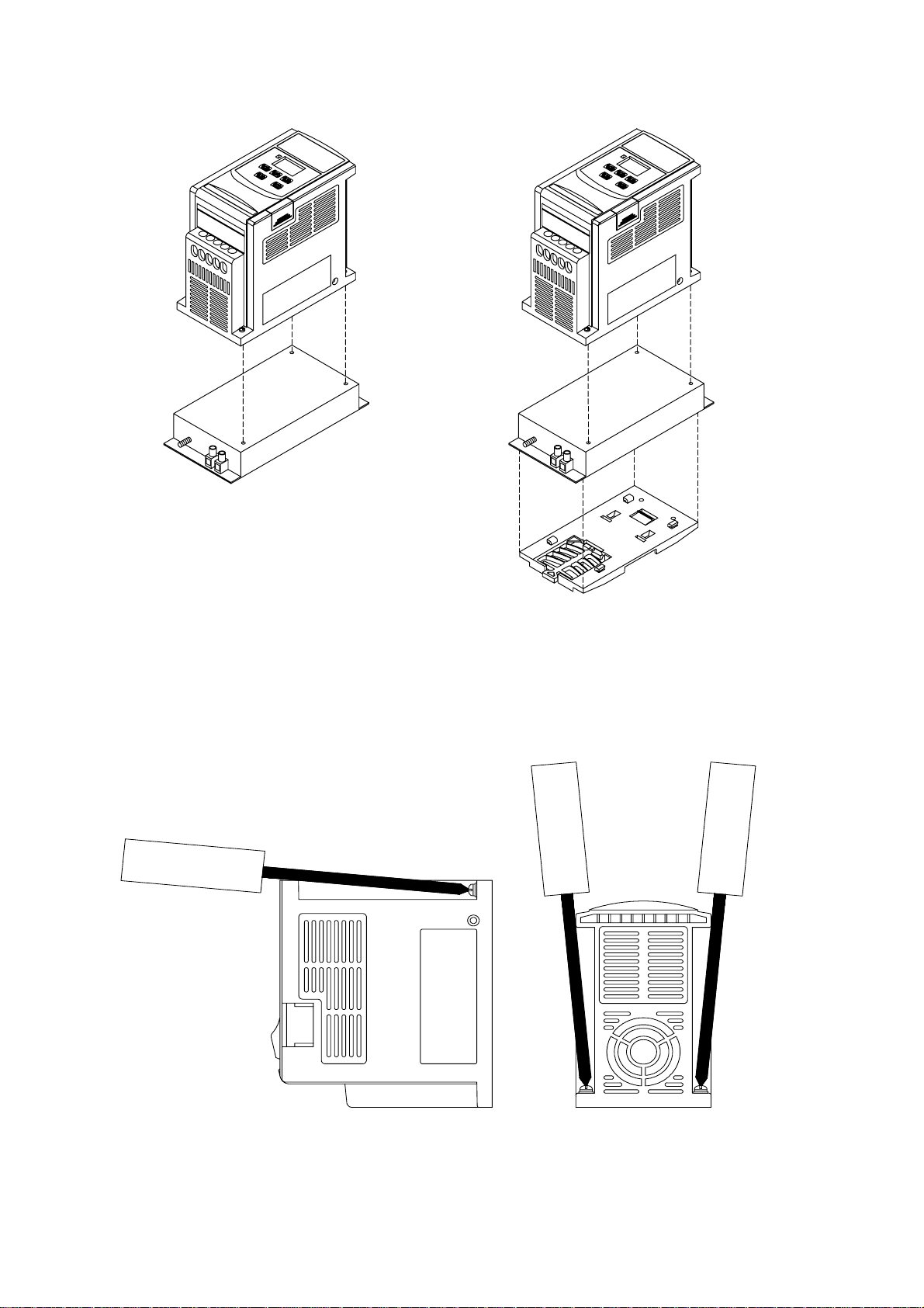
Inverter with class B filter mounted.
Inverter with class B filter & Din rail
mounted kit.
Mounting Instructions
20
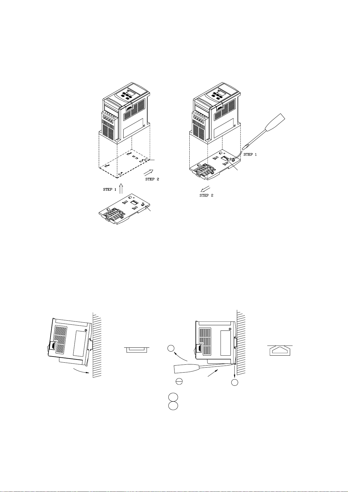
Din Rail Mounting Diagram
Step1Aim and insert the 4
retention ribs of the
DIN Rail at the 4
holes in rear panel
of inverter
Step2Push the DIN Rail
forward until the
middle rib grips
firmly with back
panel
Inserting hole
Retention rib
middle rib
Step1Use a small
screwdriver
inserting it into the
middle rib of DIN
Rail and press the
screwdriver in
order to remove
the DIN Rail from
inverter
Additional DIN Rail Installation
A mounting clamp and a 35mm width rail must be used to install the Drive on the rail.
Install Drive Dismounting Drive
First place the groove on the back of
module on the upper edge of din rail,
and then push the module down to lock
up position. Finally press the mounting
plate upward into module.
Mounti ng pl ate
Screwdr iver
1 Pull the mounting plate downward.
2 Rotate the inverter module to dismount it.
Pull mo u nting p la t e
21
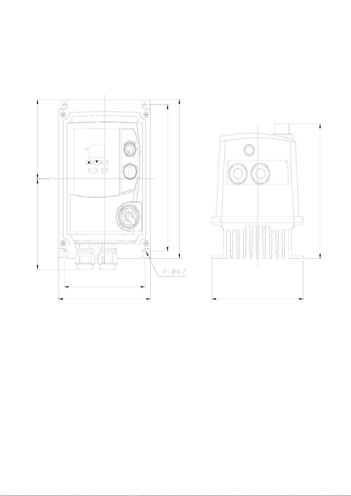
E2-2P2/2P5/201- N4X (IP65)TYPE:
102.41
116.57
RESET
RUN
STOP
133.57
DATA
ENT
DSP
FUN
117.23
0
F
R
01
188.96
204.82
173.38
133.00
UNIT : mm
22
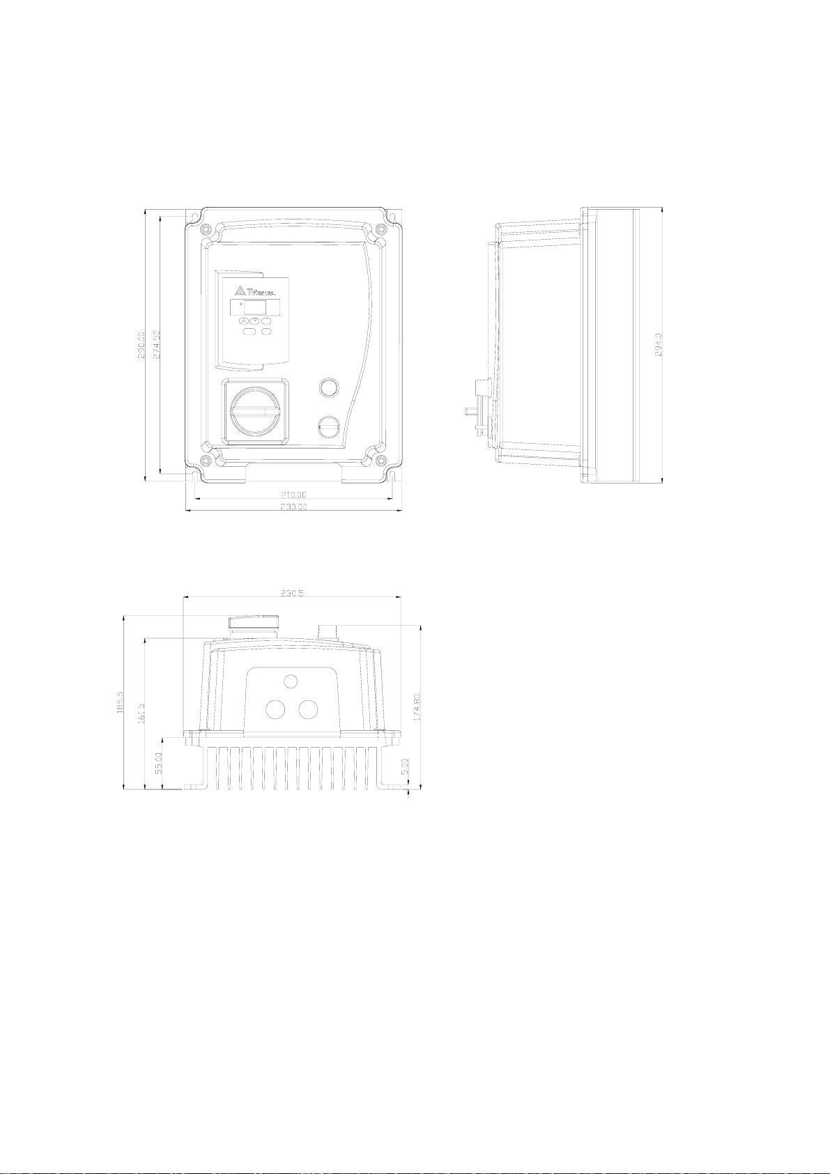
E2-202/203/401/402/403- -N4X (IP65)TYPE:
UNIT : mm
23
E2-2P2/2P5/201- - N4X(IP65)TYPE INSTALLATION :
Potentiometer
DATA
ENT
RESET
DSP
RUN
FUN
STOP
L1 L2
220-240V
5 0 /6 0 H z
Single P hases
T1 T2 T3
3 Phases
IM
CIRCUIT DIAGRAM
POWER
SWITCH
AC
200~240
50/60HZ
REV-0-FWD
SWITCH
Potentiometer
L1
L2
FW
RE
12V
10V
VI
0V
REV-0-FWD
SWITCH
POWER
SWITCH
123.40 mm
mm
NOTE :
Note :
1. POWER SWITCH , REV-0-FWD SWITCH AND
1. Power supply cable : #14 AW G
Potentiometer are only for E2-2P2~201- N4S TYPE
2. Motor cable : #16 A W G
2. Power supply cable : #14 AGE (2.0m )
3. Torque value of Screw :
3. Motor cable : #16 AGE (1.25m )
(1).P ower/Moto r ca ble (p lug -in)
4. Torque value of Screw :
Therminal : 5 kg-cm
㎡
mm
198.90 mm
㎡
(1). Power/Motor cable (plug in) Therminal : 5kg-cm(4.34 in-lb)
(2). Remote control wire : 4kg-cm(3.47 in-lb)
(3). Outer Cover (M4) : 6kg-cm(5.20 in-lb)
NOTE:
(1). Input source : single-phase(L1,L2,
T1
T2
T3
3
PHASE
IM
that it is connected to a 200/240V supply.
(2). Output Moter : three-phase(
(3). POWER SWITCH , REV-0-FWD SWITCH AND
Potentiometer are only for E2-2P2~201- N4S TYPE.
Caution :
□Do not start or stop the inve rter using the
main circuit power.
□FOR E2-2P2~201- -N4S TYPE :
Please always remain REV-0-FWD switch at 0
position. In order to keep inverter has no
running signal before power-on again after
power supply interrupted.Otherwise, injury may
result.
□FOR E2-2P2~201- -N4S TYPE :
Please always remain RE or FW switch at OFF
position. In order to keep inverter has no
running signal before power-on again after
power supply interrupted.Otherwise, injury may
result.
24
)ensuring
,T1,T2,T3).
E2-2P2/2P5/201- -N4 (WITHOUT SWITCH TYPE ) CONNECTIONS & EMC MOUNTING:
CONNECTIONS
4 x Outer cover screw
EMC MOUNTIING
Power supply
Power
cable
L1,L2,
supply
cable
Length: Max 2M
Motor cable
,T1,T2,T3
Motor cable
L1
L2
T1
TM1 terminals
200mm
T2
Cutting Length
of cable shield
T3
L1
L2
T1
T2
T3
T1
T2
T3
Cable shielding
connected to
ground clamp
Note:
TM2 Remote control
cable should be connect
to ground screw
Power supply
cable
L1,L2,
Motor cable
,T1,T2,T3
L1
L2
EMC MOUNTIING
Power supply
cable
L1,L2,
Motor cable
,T1,T2,T3
Length: Max 2M
L1
L2
T1
200mm
T2
Cutting Length
of cable shield
T3
Note:
TM2 Remote control
cable should be connect
to ground screw
Cable shielding
connected to
ground clamp
25
g
E2-2P2/2P5/201- -N4S (WITH SWITCH TYPE ) EMC MOUNTING & CONNECTIONS :
CONNECTIONS
4 x Outer cover screw
Power supply
cable
L1,L2,
Motor cable
,T1 ,T 2 ,T3
Power
supply
cable
Motor cable
Plug-in terminals
EMC MOUNTIING
200mm
Power supply
cable
L1,L2,
Motor cable
,T1,T 2,T3
Length: Max 2M
Note:
TM2 Rem ote control
cable should be connect
to ground screw
Cutting Length
of cable shield
Cable shieldin
connected to
ground clamp
26
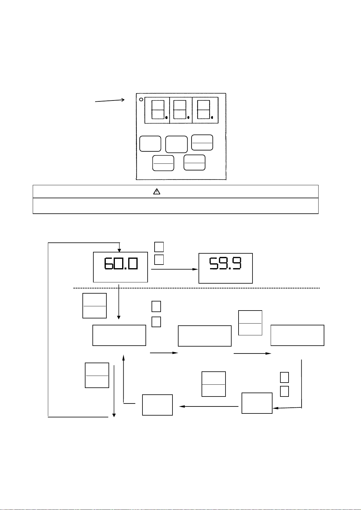
POWER LED
Chapter 3 Software Index
Keypad operating instructions
Keypad Description
▼
▲
Do not operate keypad by screwdriver or other sharp-ended tool to avoid damaging keypad.
RESET
RUN
STOP
CAUTION
DATA
ENT
DSP
FUN
Brief keypad operation flowchart
(FREQ) * 1
DSP
FUN
*
(FREQ)
(READ)
DATA
ENT
F ××
DSP
FUN
Note 1: Displayed setting of frequency when stopped. Display output frequency when running.
Note 2: The setting of the frequency can be modified either when stopped or when running.
AFTER
0.5 SEC
END
27
F ××
(WRITE)
DATA
ENT
×××
×××

Parameter List
Function F_ Function Description
0 Factory Adjustment 0 24
1 Accel. time 0.1Sec 0.1 ~ 999 S 5.0 24 *1 *3Accel. Time
Decel. Time
Operation mode 3
Motor rotation
direction
V/F Pattern 5 V/F pattern setting 1 1 ~ 6 1/4 26 *2
Frequency
upper/lower limit
SPI frequency 8 SP1 frequency 0.1Hz
JOG frequency 9 JOG frequency 0.1Hz
Start / Stop Control 10
Frequency Control 11
Carrier frequency
control
Torque compensation 13 Torque compensation gain 0.1% 0.0 ~ 10.0% 0.0% 28 *1
Stop method 14
DC braking setting
Electronic thermal
Overload protection
Multifunction input
connection point
Multi-function output 21
2 Decel. time 0.1Sec 0.1 ~ 999 S 5.0 24 *1 *3
0: Forward / Stop, Reverse / Stop
1:Run/Stop, Forward / Reverse
0: Forward
4
1: Reverse
6 Frequency upper limit 0.1Hz
7 Frequency lower limit 0.1Hz
0: Keypad
1: Terminal (TM2)
0: Keypad
1: Terminal (0~10v / 0~20mA)
2: Terminal (4~20mA)
Carrier Frequency Setting
12
0:controlled deceleration stop
1:free run to stop
DC braking time
15
DC braking injection frequency
16
DC braking level
17
Protection base on motor rated
18
current
Multifunction input terminal 1
19
(SP1) function
Multifunction input terminal 2
20
(RESET) function
Multifunction output terminal 1: Operating
Unit Range
1 0 ~ 1 0 25
1 0 ~ 1 0 25
1.0 ~ 120Hz
(1~200)*4
0.0 ~ 120Hz
(1~200)*4
1.0 ~ 120Hz
(1~200)*4
1.0 ~ 10.0Hz
(1~200)*4
1 0 ~ 1 0 27
1 0 ~ 2 0 28
1
1 0 ~ 1 0 29
0.1S 0.0 ~ 25.5S 0.5S 29
0.1Hz 1 ~ 10Hz 1.5Hz 29
0.1% 0.0 ~ 20.0% 8.0% 29
1%
1: Jog
2: Sp1
3: Emergency stop
4: External Base Block
5: Reset
6: SP2*4
2: Frequency reached
3: Fault
1 ~ 5
(1~10)*4
50 ~ 100%
(0~200)*4
Factory
setting
50/60Hz 27
0.0Hz 27
10Hz 27
6Hz 27
100% 30
Page Note
5 28
2 31
5 31
3 32
*1
*2 *3
*3
*3
28
 Loading...