

TV Ears 5.0 User Manual

TV Ears 5.0 Speaker
User Manual
Voice Clarifying Circuitry
®

v1.1.2013.5.0S
TV Ears logos, pictures, design, and content ©2013 TV Ears, Inc. All rights reserved.
Keep these instructions in a safe place for future reference.

Important Safety Information
Introduction
Product Diagram
What’s Included
Ideal TV Ears Placement
Installation
Step 1 - Place & Power the Transmitter
Step 2 - Optical Digital Installation
Step 2.1 - RCA Analog Installation
Step 2.2 - 3.5mm Cord Analog Installation
Step 2.3 - Coaxial Digital Installation
Step 3 - Place & Power the Speaker
Using the System & Features
Caring for your Product
Troubleshooting
Appendix
Warranty Information
Manufacturer Declarations
Technical Specications
Contact Information
2
3
4
5
6
8
9
10
11
12
13
14-15
16
17
19
20
21
Rear Cover
Table of Contents

TV Ears, Inc. asks that you read all instructions completely and heed all
warnings to insure proper handling and prevent any injuries. Failure to
act in accordance with TV Ears, Inc.’s instructions can lead to physical
harm or injury.
For safety purposes, do not deface the prongs on the AC adapters. If the
provided plug does not t into your outlet, purchase the correct adapter
or consult an electrician for further assistance.
Only use attachments and accessories specied by TV Ears, Inc. with
your TV Ears system.
Warning: To prevent possible hearing loss, do not listen at high volume
levels for long periods of time.
Warning: To reduce the risk of re or electric shock, do not expose the
TV Ears product to rain or moisture. The TV Ears product should not be
exposed to dripping or splashing liquids. Do not place objects lled with
liquid such as vases on or near the TV Ears product.
Warning: Keep batteries out of reach of children. Discard the batteries
appropriately and carefully. If swallowed, call The National Button
Battery Ingestion Hotline at 1-202-625-3333.
Warning: The magnetic eld emitted by the TV Ears speakers is minimal.
When used as indicated, TV Ears headsets should not cause magnetic
interference with pacemakers or internal debrillators. The magnetic
eld strength of the speakers is less than 1 Gauss when within 1 inch (3
cm) of the pacemaker or internal debrillator. It is recommended that
the user keep the ear tips at least 1 inch away from any pacemaker or
internal debrillator. If you have concerns, we recommend you contact
your physician.
! Important Safety Information
2

3
Introduction
Thank you for purchasing from TV Ears and welcome to the family!
This User Manual is designed to give you the most information
possible and answer all the questions you might have when
installing and using your new product.
In this manual, we will demonstrate the ideal set up as well as
show you how to successfully install your product with illustrated
step-by-step instructions. You will learn what each piece is used
for, how to use all of the features available to you, and how to
troubleshoot the issues most commonly experienced by other
users. We aim to cover any pitfalls you might experience, and
give you tips for best practices.
Towards the back of the manual, you will nd information on our
warranty, technical specications of your product, and support
contact information just in case you have any questions.
Again, we welcome you to the TV Ears family and wish you happy
TV listening!
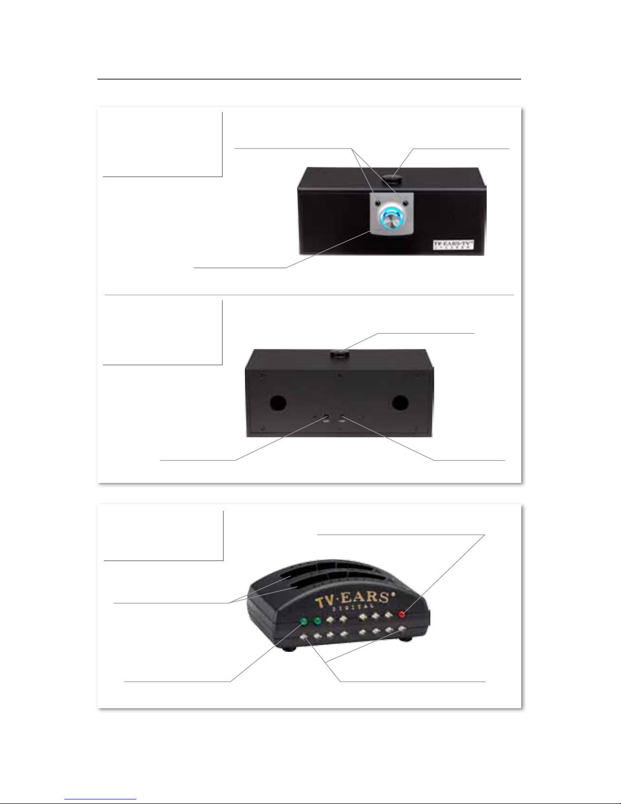
Product Diagram
4
Speaker
(front)
Transmitter
Infrared Signal Lights
Digital Connectivity Light
Charging Lights
Charging Cradles
360º Receiver
Volume Knob
Headphone Ports
Power Port Music Port
360º Receiver
Speaker
(back)
5
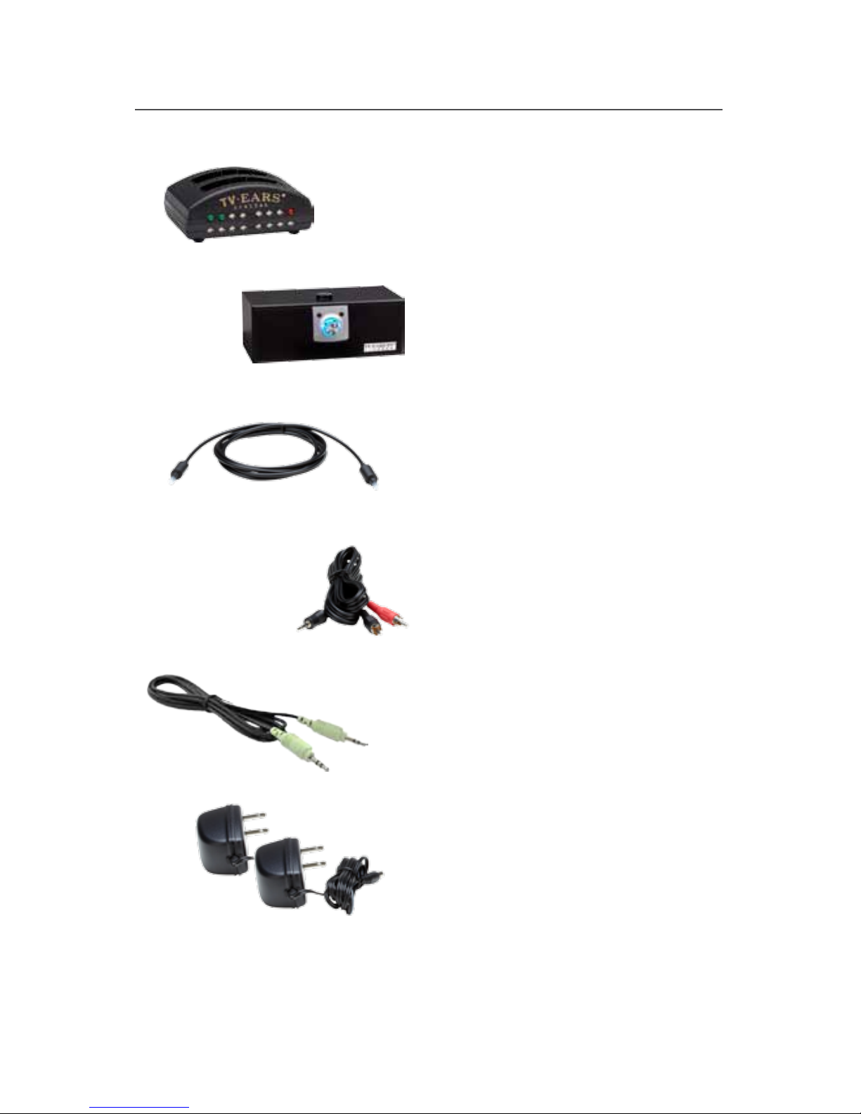
What’s Included
5.0 Dual Digital Transmitter
Wireless 5.0 Speaker
Optical Digital Audio Cord
RCA Analog Audio Cord
3.5mm Analog Audio Cord
Two AC Power Adapters
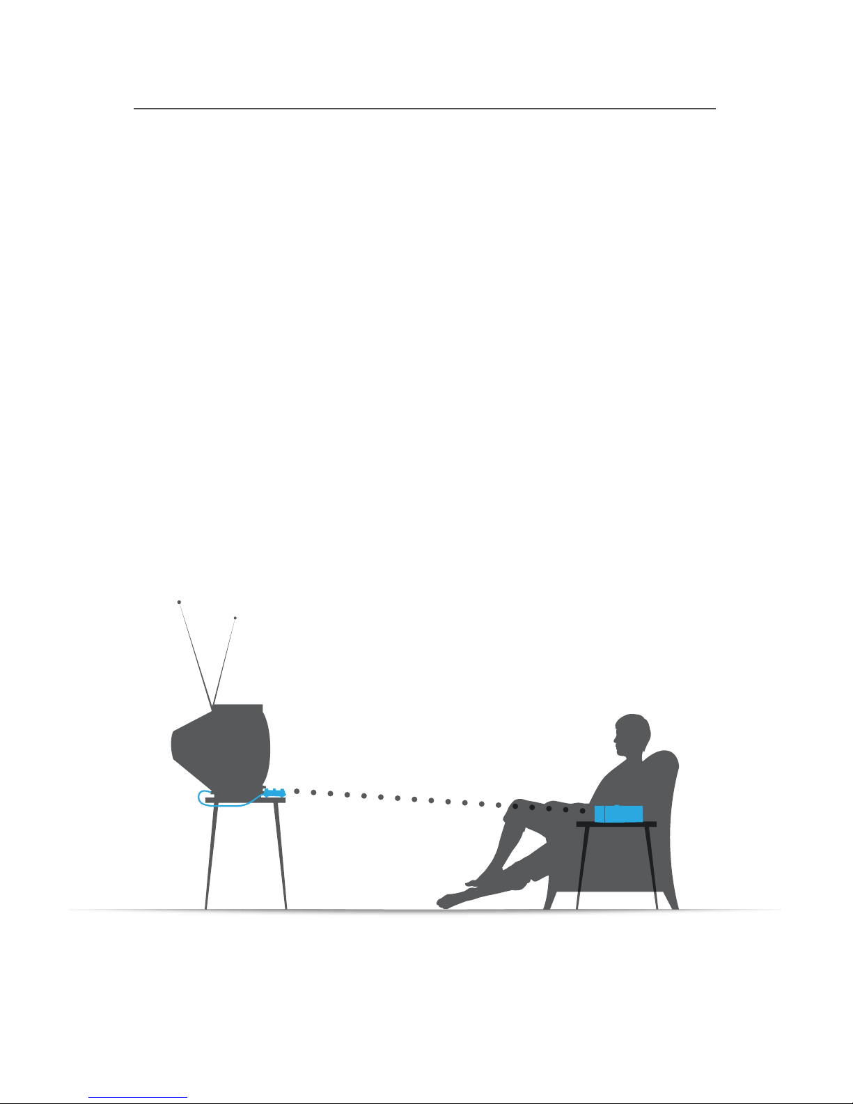
Ideal TV Ears Placement
6
Every wireless TV Ears system utilizes infrared technology to
send audio signals from the transmitter to the speaker.
Infrared technology requires a direct line-of-sight from the
transmitter to the receiver (or speaker) to successfully transmit
audio signals. Therefore, when installing any wireless TV Ears
system, you will have to be sure the transmitter has a direct lineof-sight with the speaker when the speaker is in use.
For the best results, the transmitter should be placed on a at
surface that is three to ve feet from the ground and should be
facing directly towards the seating area where the speaker will
be used. Make sure that nothing is blocking the signal between
the transmitter and speaker (ie. books, newspapers, etc.).

Installation
pgs. 8-13
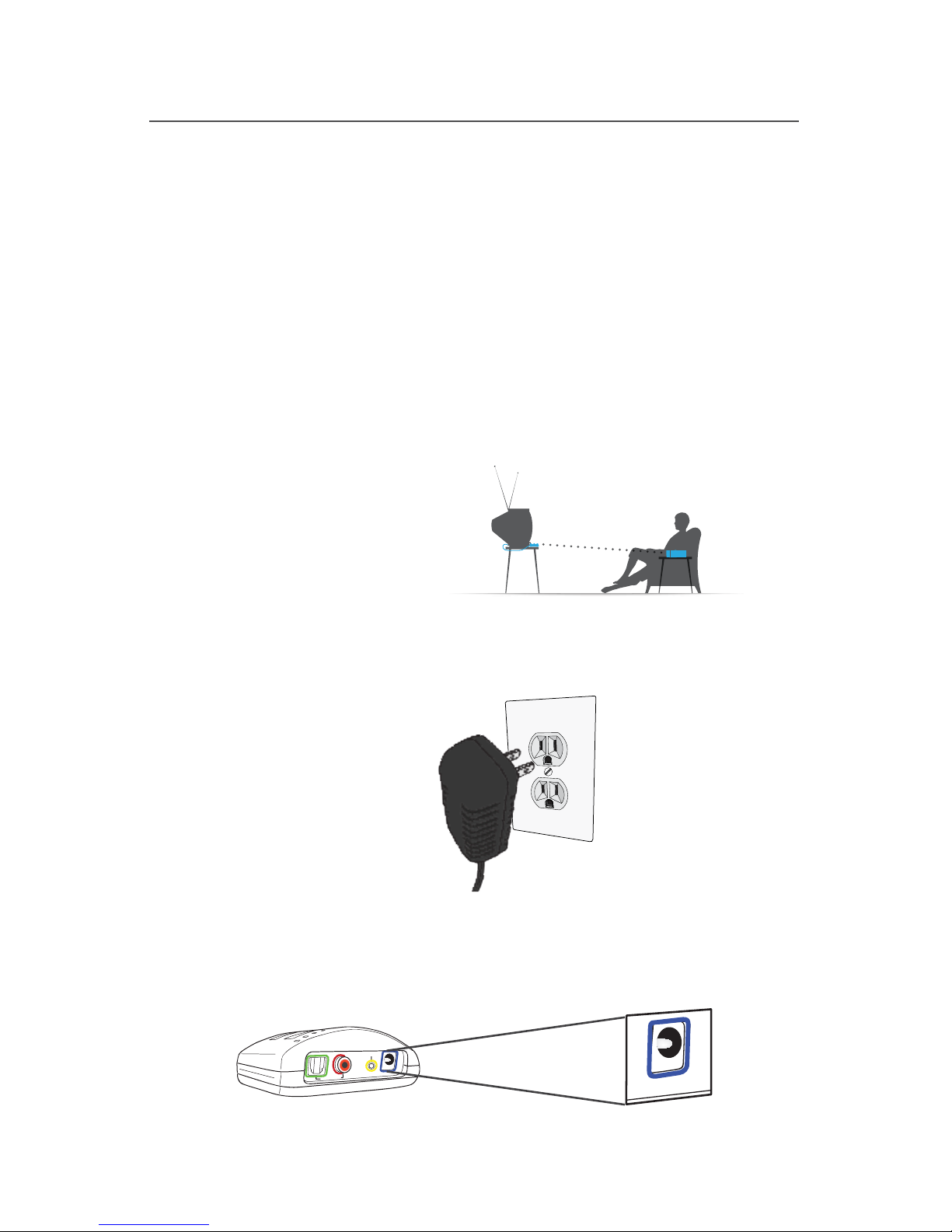
Step 1 - Place & Power the Transmitter
8
This step explains where to place the transmitter for the best
performance as well as how to power the transmitter.
The infrared diodes on the transmitter must be in direct line-ofsight with the speaker when using the system for best performance.
There cannot be anything blocking the direct signal, otherwise there
will be no audio received and no sound heard.
Place the transmitter on a at surface that is 3 to 5 feet
above the ground. Be sure it is pointed to the seating area
where the speaker will be used.
Plug the AC adapter into a standard electrical outlet or surge
protector.
Plug the end of the AC adapter into the port labeled “12V”
on the back of the transmitter. The correct port has a blue
border around it.
1
2
3
Digital Audio In
Analog Audio In
12
V
12v
Power Port
For assistance, call us at 866-611-9934
9
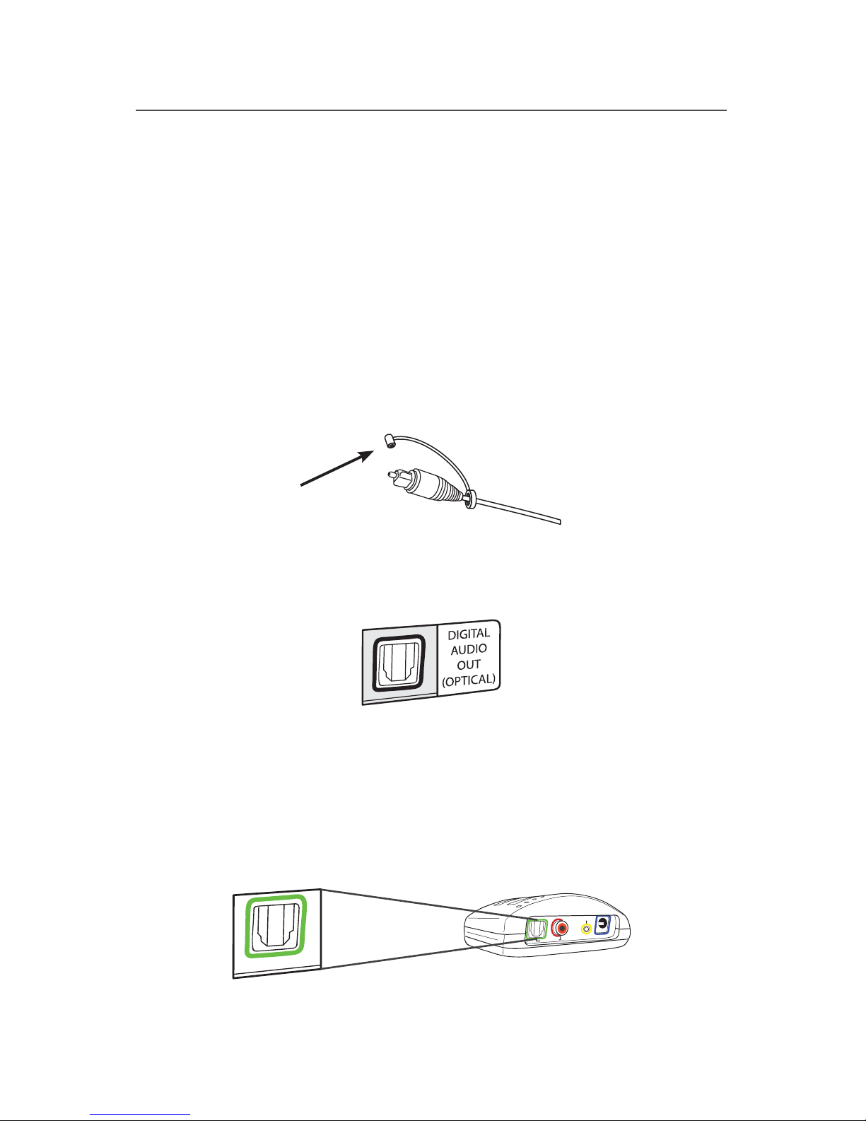
Step 2 - Optical Digital Installation
This step will instruct you on how to connect the TV Ears
transmitter to your television, satellite, or cable box using an
optical digital audio cord.
• If you cannot get to the back of your TV, you can also use these
instructions to install the system to your cable or satellite box.
• Be aware that the “Audio” ports on the front of your television are
typically “Audio In” ports and will not send audio to your speaker.
Remove the plastic caps from both ends of the optical digital
audio cord.
Plug either end of the optical audio cord into the “Digital
Audio Out (Optical)” port on the back of the TV.
Plug the other end of the optical digital audio cord into the
port on the back of the transmitter labeled “Digital Audio
In”. The correct port has a green border around it. You should
hear and feel a ‘click’ when it has been pushed in all the way.
Optical
Digital Audio
Digital Audio In
Analog Audio In
12
V
1
2
3
For assistance, call us at 866-611-9934
 Loading...