

Replace batteries With Maxell, CR2032, 3-Volt
Coin Cell ONLY. Use of another battery may
present risk of fire or explosion.
The disposal of used batteries is governed by law in
many countries world-wide. Therefore, please
check your local regulations prior to battery
disposal.
Responsive Innovations
ResponseCard RF LCD
User’s Manual
RCRF-03 User’s Manual Ver. Preliminary

REGULATORY INFORMATION
FCC Statement
This product has been tested and found to comply
with Part 15 of the FCC Rules. Operation it subject
to the following conditions: it may not cause
harmful interference and must be accept
interference received, including interference that
may cause undesired operations.
Changes or modifications not expressly approved
by the party responsible for compliance could void
the user’s authority to operate the equipment.
Canada Statement
This Class B digital apparatus complies with
Canadian ICES-003.
Cet appareil numérique de la classe B est conforme
à la norme NMB-003 du Canada.
Safety Statement
WARNING, batteries may explode if mistreated.
Do not recharge, disassemble or dispose in a fire.

pressed. Valid keys are ‘0’ through ‘9’.
Valid RF Channels are ‘1’ through ‘82’.
While in Set RF Channel mode pressing a
valid key will cause the status LED to
briefly flash YELLOW. When Set RF
Channel Mode exits, the status LED
indicates the result as follows:
SOLID GREEN - Set
RF Channel successful
SOLID RED - Set
RF Channel failed
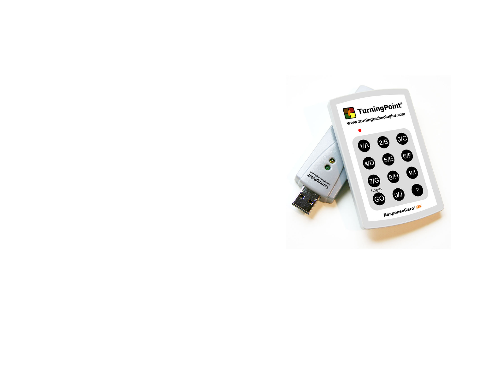
The RI RF LCD Keypad is designed to be used with
the RI RF Receiver connected to a PC. The keypad
transmits key presses via radio frequency to the RF
receiver for accumulation by the PC. The keypad
consists of 12 data keys (0-9, Go/Login, ?) and a
single status LED.
In Idle state, the LED is OFF. The keypad returns
to idle state after completion of a key press.
Standard Operation Mode:
Initially the status LED is OFF.
Pressing a single key will cause the key to be
transmitted to the receiver. After pressing a key the
status LED shows status as follows:
Quick YELLOW Blink then OFF Receiver is not accepting data at this time
BLINKING YELLOW - key is
being transmitted (up to 8 seconds)
SOLID GREEN - key
transmit successful - ready for input
SOLID RED - key
transmit failed – ready for input
BLINKING GREEN -
Receiver indicated correct answer
BLINKING RED -
Receiver indicated incorrect answer
Overview:

Blinking Green and Blinking Red will only occur if
the Receiver is configured to indicate a correct or
incorrect answer (CORRECT POLLING mode).
Setup Modes:
Active at any time the keyboard is ready for input.
Match Mode (Check RF connection)
Press ‘?’
In order for Match Mode to operate properly
an RF Receiver MUST also be placed into
Match Mode.
Quick YELLOW Blink then OFF Receiver is not accepting data at this time
BLINKING YELLOW - key is
being transmitted
SOLID GREEN - RF
receiver found, but not in Match Mode
SOLID RED - Key
transmit failed
BLINKING GREEN - RF
receiver in Match Mode found
BLINKING RED - RF
receiver found, but not in Match Mode
Auto Match Mode(find RF Receiver)
Press Go/Login, while holding Go/Login,
quickly press and hold ‘?’. Release both
keys.
In order for Auto Match Mode to operate
properly an RF Receiver MUST also be
placed into Match Mode, otherwise the
keypad will always indicate that Auto Match
Mode has failed.
BLINKING YELLOW search is in progress
SOLID GREEN search successful – Match Mode exits
SOLID RED -
search failed – Match Mode exits
Set RF Channel
Press GO/LOGIN
Set RF Channel mode is indicated by the
status LED flashing a RED then GREEN
pattern. Set RF Channel mode exits
automatically after three valid keys are
pressed, if no valid key is pressed for 5
seconds, or at any time an invalid key is
 Loading...