

Page 1
Arraying and Rigging
TCS series
TCS Arraying and Rigging
This document explains how TCS loudspeakers can be arrayed and the reasons for the rotatable
horns in some models. The TCS-122 and TCS-152 both feature Turbosound’s unique Dendritic high
frequency waveguide. This can be rotated for two reasons:
1. To allow a single speaker to be mounted horizontally but still retain the wider horizontal
pattern, or
2. To allow two or more speakers of the same to be arrayed with minimal interference
The second application is explained here in detail.
One of the benefits of the Dendritic waveguide is its exceptional coverage pattern and sharp edge-ofpattern cut-off as demonstrated in Flex Array. The sharp cut-off works either vertically or horizontally,
depending on which way the horn is rotated.
To explain this further, the TCS-122 and TCS-152
feature exceptional pattern control either left/right or
up/down depending on how the horn is rotated. This
allows them to be arrayed with adjacent speakers
without lobes or destructive interference. So the true
arrayable benefit of the Dendritic is
plane of the Dendritic device
up/down depending on orientation. The other plane
of the Dendritic device functions in a similar way to a
standard horn.
i.e. either left/right or
in the physical
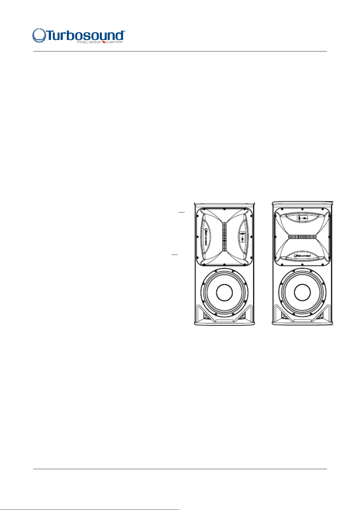
The diagram here shows a TCS-122 with the horn in
two possible orientations. The one on the left is the
typical orientation, so for example the TCS-122/94
model has a dispersion pattern of 90 degrees wide
by 40 degrees in the vertical. The box on the right
shows the box with the horn rotated to give 40
degrees in the horizontal and 90 degrees in the vertical.
So the speaker on the left has a very controlled vertical pattern, whereas the one on the right (the
same speaker with the HF horn rotated) has a very controlled horizontal pattern.
The TCS-122 and TCS-152 are both available with three dispersion options: 60° x 40°, 90° x 60° and
60° x 40°. However note that only the 40 degree boxes benefit from being tightly arrayed, i.e with the
sides touching. So in a cluster of two or three tight packed boxes, you should use either the 60° x 40°
or 90° x 40° models and the horns should be orientated to give 40° dispersion in the horizontal plane.
The TCS-122 and TCS-152 are double trapezoidal boxes and it is this feature, in combination with the
rotatable horns that gives you the flexibility to build so many cluster options. The simple rule is that
the side that is touching the adjacent speaker needs to be orientated to 40 degrees.
The following options only apply to TCS-122 and TCS-152 models with Dendritic horns. The TCS-1561
and TCS-61 use conventional horns.
TCS series Arraying and Rigging - Page 1
Page 2
Arraying and Rigging
TCS series
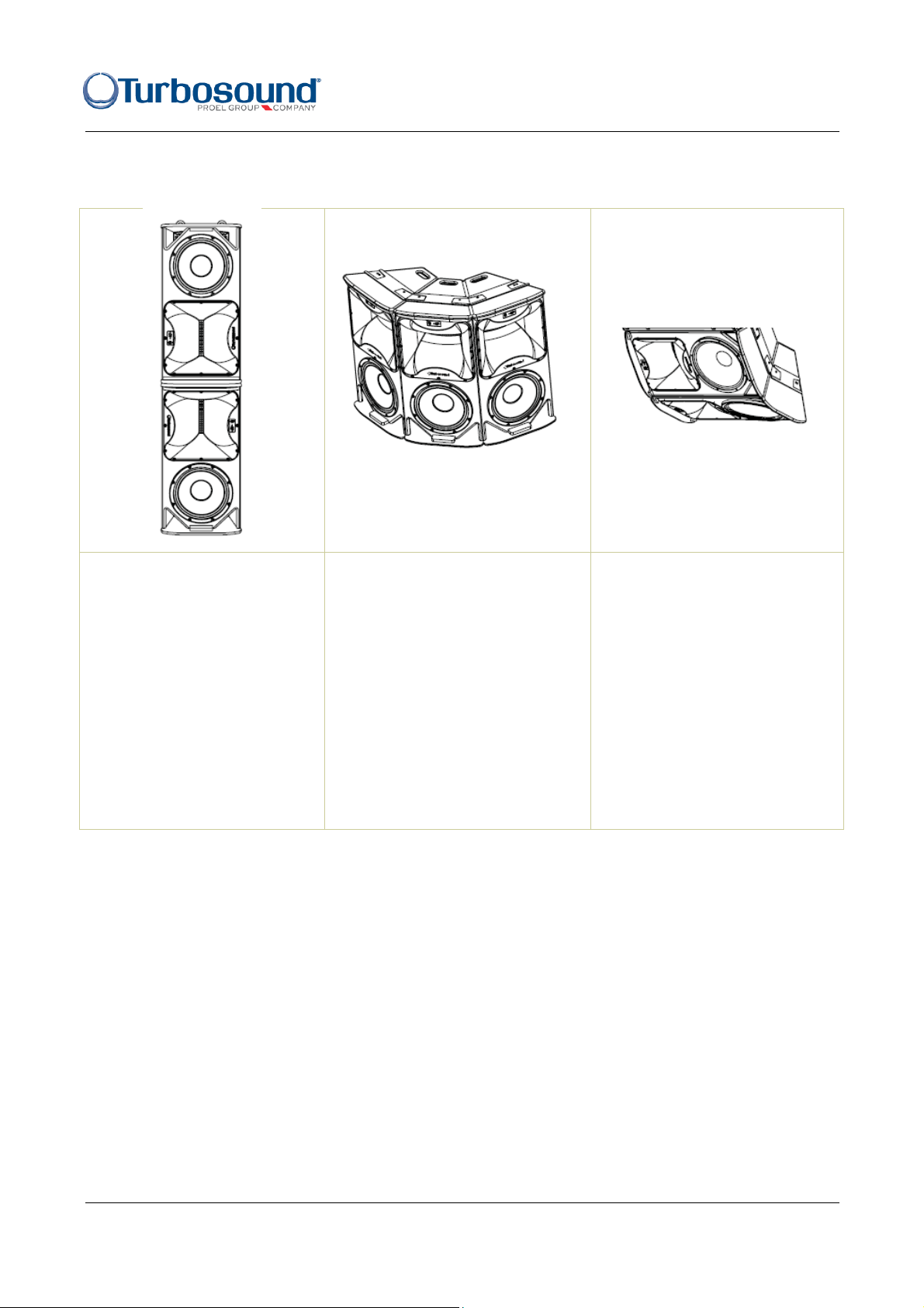
In this example the TCS-122/94
loudspeakers with horns in the
standard 90° x 40° orientation
are tight packed vertically
horn-to-horn, providing a
combined coverage of 90°
horizontal by approximately
80° vertical, with a useful
vertical beam and a mid-range
lobe that projects well down a
longer, thinner room.
These examples are based on the 90° x40° model. If using the 60° x40° models, a further three
coverage pattern options of 60° x 80°, 120° x 60°, and 60° x 80° would be available to you, depending
on the shape of the room.
The HF horns in this horizontal
array of TCS-122/94 boxes have
been rotated to give individually
40° horizontal by 90° vertical. The
horizontal coverage patterns add
up to give combined dispersion
of 120° horizontal by 90° vertical.
This example shows how the
same coverage pattern as the
vertical array on the far left can
result from a completely
different physical array. The HF
horns are rotated to give 40°h x
90°v and then the whole array
is assembled horizontally to
give combined coverage of 90°
horizontal by 80° vertical.
Rigging options
All of the TCS boxes have rigging points on the top, bottom and both sides, so they can be mounted
practically any way you like. For example, one option is to mount a single TCS-122 upside down to
get the HF waveguide closer to the audience.
Flying single boxes
This can be simply achieved with M10 eyebolts, WB-20 and WB-55 wall brackets, CB-55 ceiling
brackets, and OmniMount™ speaker brackets, for which bolt patterns are provided on the back of the
TCS series Arraying and Rigging - Page 2
Page 3
Arraying and Rigging
TCS series
cabinets where appropriate.
Flying multiple cabinets
When creating loudspeaker arrays the essential components are a pair of steel flyplates fitted to the
sides of each flown cabinet, ensuring that all the rigging is steel-to-steel without any load being taken
through the cabinets’ woodwork. Sets of joiners mate with the flyplates to connect one cabinet to the
next adjacent cabinet.
Following is a summary of the kits required and their component parts.
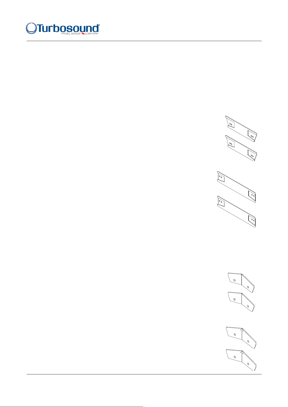
FP-1 KIT 07G0335
Consists of a pair or steel flyplates that fit both the TCS-122 and TCS-152 cabinets.
1 x FP-1 kit is required for each cabinet that is to be arrayed.
The FP-1 kit includes two flyplates, four M10 x 40mm bolts and four M10 spring
washers.
FP-2 KIT 07G0340
Consists of a pair of steel flyplates for the flyable TCS-B15A and TCS-B15B
subs. 1 x FP-2 kit is required for each sub cabinet. The TCS-B15A is
dimensioned to fly with the TCS-122, while the TCS-B15B is dimensioned to fly
with the TCS-152.
The FP-2 kit includes two plates, four M10 x 40mm bolts and four M10 spring
washers.
With the flyplates installed on each box to be flown, now select the appropriate inter-cabinet couplers
to connect the flyplates from one box to the flyplates of another.
ICC-2H KIT 07G0345
A pair of steel inter-cabinet couplers for linking two TCS-122 cabinets together.
The couplers fit into the recesses provided in the flyplates and are secured using
the M10 bolts and washers that are supplied with the FP-1 flyplate kits.
ICC-3H KIT 07G0350
A pair of steel inter-cabinet couplers for linking two TCS-152 cabinets together.
The couplers fit into the recesses provided in the flyplates and are secured using
the M10 bolts and washers that are supplied with the FP-1 flyplate kits.
TCS series Arraying and Rigging - Page 3
Page 4

Arraying and Rigging
ICC-4H KIT 07G0355
A pair of steel inter-cabinet couplers for linking two TCS-B15 subs together.
These can be either TCS-B15A or TCS-B15B versions, but in a cluster both subs
should the same type. The couplers fit into the recesses in the flyplates and are
secured using the M10 bolts and washers that are supplied with the FP-2
flyplate kits.
TCS series
ICC-5H 07G0360
A pair of steel inter-cabinet couplers for linking a TCS-152 cabinet to a TCSB15B sub. Each box needs their respective FP-1 and FP-2 flyplate kits of course.
The couplers are handed i.e. there are left and right versions. The couplers fit
into the recesses in the flyplates and are secured with the M10 bolts and
washers that are supplied with the FP flyplate kits.
ICC-6H 07G0365
A pair of steel inter-cabinet couplers for linking a TCS-122 cabinet to a TCS-B15A
sub. Each box needs their respective FP-1 and FP-2 flyplate kits of course. As with
the ICC-5H kit, the couplers are handed left and right. The couplers fit into the
recesses in the flyplates and are secured with the M10 bolts and washers that are
supplied with the flyplate kits.
ICC-2V 07G0330
A pair of steel inter-cabinet couplers for flying two TCS-122 or TCS-152 cabinets in
a vertical column with one cabinet inverted to position the horns adjacent to each
other. FP-1 kits are not needed to assemble this configuration; all that is required is
one ICC-2V kit per hang.
The kit includes two plates, four M10 x 40mm bolts and four M10 spring washers.
TCS series Arraying and Rigging - Page 4
Page 5

SB-61 07G0375
The SB-61 is a swivel bracket used to hang the TCS-61 in standalone
applications such as ceiling mounting in bars or clubs, or as an underbalcony fill. It consists of two parts: a ceiling plate and a speaker plate,
allowing each part to be fixed individually and then assembled and
angled to achieve the desired coverage.
Arraying and Rigging
TCS series
The SB-61 can also be used to hang the TCS-61 underneath the wider
TCS-152 cabinet, with the facility to alter the downward angle.
ICC-61 07G0370
To hang the TCS-61 as a downfill speaker underneath the TCS-122, you
will need a pair of ICC-61 inter-cabinet links fitted between the cabinets
which positions the TCS-61 at an optimum angle to the TCS122.
Following are some diagrams that illustrate these components and kits in action.
In this example cluster three TCS-122
cabinets are tight packed together using
FP-1 flyplates on top and bottom and
tied together with ICC-2H couplers. The
horns are rotated to 40°h by 90°v and
the cluster produces combined
coverage of 120°h by 90°v. Pick up the
array using M10 eyebolts attached to
the inside flypoints on the two outer
boxes. Parts required:
3 x FP-1 kits (6 pcs)
2 x ICC-2H kits (4 pcs)
2 x M10 eyebolts
TCS series Arraying and Rigging - Page 5
Page 6

Arraying and Rigging
TCS series
This cluster of three TCS-152
cabinets is assembled with FP-1
flyplates and ICC-3H couplers.
Again the horns are rotated to
40°h x 90°v, giving combined
cluster coverage of 120°h x 90°v.
Parts required:
3 x FP-1 kits (6 pcs)
2 x ICC-3H kits (4 pcs)
2 x M10 eyebolts
This diagram shows how bass
cabinets are combined in an array
of TCS-152 cabinets. The
mid/highs are fitted with FP-1
flyplates and the TCS-B15B bass
cabinets with FP-2 flyplates. Three
types of inter-cabinet couplers
complete the cluster as shown.
Parts required:
2 x FP-2 kits (4 pcs)
2 x FP-1 kits (4 pcs)
1 x ICC-4H kit (2 pcs)
1 x ICC-5H kit (2 pcs)
1 x ICC-3H kit (2 pcs)
TCS series Arraying and Rigging - Page 6
Page 7

Arraying and Rigging
TCS series
A simple vertical hang of
TCS-122 or TCS-152
cabinets with vertical
couplers. The cluster is
suspended on M10
eyebolts with a third
eyebolt for a pull-back
attached in the centre of
the lower cabinet. Parts
required:
1 x ICC-2V kit (2 pcs)
3 x M10 eyebolts
The TCS-61 shares the
same width dimension as
the TCS-122, providing an
ideal visually discreet
downfill application. The
cluster is suspened with
M10 eyebolts, with a
further eyebolt in the centre
of the TCS-122 as a pullback. Parts required:
1 x ICC-61 kit (2 pcs)
3 x M10 eyebolts
TCS series Arraying and Rigging - Page 7
Page 8

Arraying and Rigging
TCS series
Important notes on rigging
As with all rigging, the flying of these arrays should only be carried out by a professional rigger.
The Turbosound rigging system has been designed and constructed to a high standard of safety, and
tested to the most demanding of specifications. In order to ensure the highest safety standards, this
information on the assembly and safe use of rigging accessories must be understood and followed.
Only use Turbosound recommended rigging accessories, which are specifically designed for their
intended purpose. Do not use Turbosound rigging with other types or brands of loudspeakers. This
practice may compromise safety standards and Turbosound will not be responsible for damage or
injury so caused. Do not modify the rigging accessories, or use them in a way other than that
described in this user manual. Rigging components supplied as part of a complete assembly are noninterchangeable and must not be exchanged with the component parts of any other assembly. The
component parts of a Turbosound rigging accessory must only be assembled using the fasteners and
methods of assembly recommended in this guide. The use of fasteners and methods of assembly not
specified or approved by Turbosound may result in an unsafe rigging assembly. Welding, or any
other means of permanently fixing rigging components to each other or to cabinet fixing points is not
allowed. Rigging assemblies must only be assembled using the appropriate parts and fixings as
specified in this manual using the specific mounting instructions. Rigging components or assemblies
must only be fixed to Turbosound loudspeaker cabinets using the cabinet fixing points, assembly
methods and fasteners specified in this guide and the specific mounting instructions. When
assembling the loudspeaker array ensure that all fixings are securely tightened before lifting the
array.
Secondary Safeties
All loudspeaker clusters flown in theatres, studios or other places of work and entertainment must, in
addition to the principle load bearing means of suspension, be provided with an independent, and
properly rated and securely attached secondary safety. Only steel wire ropes or steel chains of an
approved construction and load rating may be used as secondary safeties.
Safety Inspections
Carefully inspect rigging systems components and cabinets for defects or signs of damage before
proceeding to assemble a flown array. If any parts are damaged or suspect, DO NOT USE THEM.
Regular, more rigorous test and inspection of rigging components must also be carried out. Safety
legislation and test and inspection requirements will vary from country to country. In most cases,
annual independent test and inspection by a suitably approved and qualified inspector will be
required. Users must ensure compliance with all applicable safety requirements. Turbosound
recommends regular safety inspections and further recommends that a logbook be kept detailing the
test and inspection history of each Turbosound rigging accessory. Always wear protective headwear,
footwear and eye protection in accordance with local regulations. Anyone involved in flying ANY
sound system should take note of the following advice:
The rigging of a flown sound system may be dangerous unless undertaken by qualified personnel
with the required experience and certification to perform the necessary tasks. Fixing of hanging
points in a roof should always be carried out by a professional rigger and in accordance with the local
rules of the venue. The house rigger and/or building manager must always be consulted.
TCS series Arraying and Rigging - Page 8
 Loading...