


TCS-1061
Quickstart and Rigging User Guide
(Please refer to www.turbosound.com for the latest updates)
Version 1.0
Quick Start Guide
TCS series
The Flying Systems
TCS series Quickstart Guide v1.0 - Page - 2

Quick Start Guide
TCS series
Safety Information
Safety Notes on Rigging
The Turbosound rigging system has been designed and constructed to a high standard of safety, and
tested to the most demanding of specifications. In order to ensure the highest safety standards, this
information on the assembly and safe use of rigging accessories must be understood and followed.
Only use Turbosound recommended rigging accessories, which are specifically designed for their intended purpose. Do
not use Turbosound rigging with other types or brands of loudspeakers. This practice may compromise safety
standards and Turbosound will not be responsible for damage or injury so caused. Do not modify the rigging
accessories, or use them in a way other than that described in this user manual. Rigging components supplied as part
of a complete assembly are non-interchangeable and must not be exchanged with the component parts of any other
assembly. The component parts of a Turbosound rigging accessory must only be assembled using the fasteners and
methods of assembly recommended in this guide. The use of fasteners and methods of assembly not specified or
approved by Turbosound may result in an unsafe rigging assembly. Welding, or any other means of permanently fixing
rigging components to each other or to cabinet fixing points is not allowed. Rigging assemblies must only be
assembled using the appropriate parts and fixings as specified in this manual using the specific mounting instructions.
Rigging components or assemblies must only be fixed to Turbosound loudspeaker cabinets using the cabinet fixing
points, assembly methods and fasteners specified in this guide and the specific mounting instructions. When
assembling the loudspeaker array ensure that all fixings are securely tightened before lifting the array.
Secondary Safeties
All loudspeakers flown in theatres, studios or other places of work and entertainment must, in addition to the principle
load bearing means of suspension, be provided with an independent, properly rated and securely attached secondary
safety. Only steel wire ropes or steel chains of an approved construction and load rating may be used as secondary
safeties. Plastic covered steel wire ropes are not permitted for use as secondary safeties.
Safety Inspections
Carefully inspect rigging systems components and cabinets for defects or signs of damage before proceeding to
assemble a flown array. If any parts are damaged or suspect, DO NOT USE THEM.
Regular, more rigorous test and inspection of rigging components must also be carried out. Safety legislation and test
and inspection requirements will vary from country to country. In most cases, annual independent test and inspection
by a suitably approved and qualified inspector will be required. Users must ensure compliance with all applicable safety
requirements. Turbosound recommends regular safety inspections and further recommends that a logbook be kept
detailing the test and inspection history of each Turbosound rigging accessory. Always wear protective headwear,
footwear and eye protection in accordance with local regulations. Anyone involved in flying ANY sound system should
take note of the following advice:
The rigging of a flown sound system may be dangerous unless undertaken by qualified personnel with the required
experience and certification to perform the necessary tasks. Fixing of hanging points in a roof should always be carried
out by a professional rigger and in accordance with the local rules of the venue. The house rigger and/or building
manager must always be consulted.
TCS series Quickstart Guide v1.0 - Page - 3

Quick Start Guide
TCS series
Flying system components have been individually tested in accordance with the following regulations:
• The Health and Safety at Work Act 1974
• The Supply of Machinery (Safety) Regulations 1992
• The Lifting Operations and Lifting Equipment Regulations 1998
General Description
To take full advantage of the extremely flexible properties of the TCS series loudspeaker, the rigging system is designed
to be intuitive, inherently safe, flexible, and simple to use. The load is taken entirely through the steel flygear and not
through the cabinet’s woodwork.
Rigging Parts
The rigging system consists of external steel flyplates fitted into rebates on the short sides of the loudspeaker enclosure
forming the pivot point about which cabinets can be angled, working together with flyplates fitted towards the rear of
the cabinet which mate with the flyplates of the cabinet above, providing a range of inter-cabinet angles.
A kit of parts is supplied with each TCS-1061 loudspeaker cabinet, consisting of:
8 x M6 x 35mm csk hex head screws
2 x front flyplate
2 x rear flyplate (handed left and right)
4 x M6 x 45mm high tensile socket head screws
4 x M6 split washers
1 x 4mm Allen key
1 x 5mm Allen key
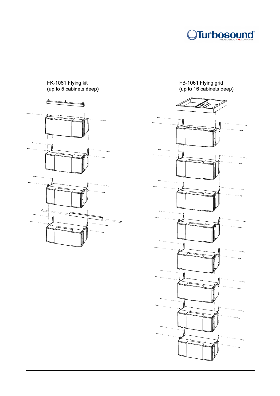
The rigging system includes all the necessary
hardware to support a column of up to 5 cabinets
(using the FK-1061 flying kit), or up to 16 cabinets
(using the FB-1061 flying grid).
The rigging design allows the creation of arrays that
can be assembled quickly and with full control of the
vertical angles between enclosures and the array’s
vertical inclination. A range of inter-cabinet angle
adjustment is provided in 2° increments from 0° to
16°.
TCS series Quickstart Guide v1.0 - Page - 4

Quick Start Guide
TCS series
FK-1061 FLYING SYSTEM WILL SUPPORT A COLUMN OF UP TO 5 CABINETS DEEP
FK-1061 Flying Kit
Enables suspension of a column of TCS-1061 cabinets
up to 5 deep from a single flybar, and utilising an
identical flybar fitted with pull-back links to provide a
pull-back for the whole cluster. The kit consists of:
2 x flybars
2 x pull-back links
2 x blanking plates
2 x M6 x 20mm socket head screws
2 x M6 split washer
The single flybar provides three pick up points to allow for either a single lift point or double lift points.
Rigging an Array of up to 5 cabinets with the FK-1061 flying kit
1. Attach a flybar to the front flying strips of the first cabinet using the M6 x 45mm high tensile socket head bolts
and split washers provided. This flybar will become the lifting bar and is used to hang the array. Attach this bar
to the external rigging or motor.
2. Remove both of the rear flyplates from the first cabinet and replace them with the two blanking plates supplied
with the flying kit.
3. Lift the flybar array together with the first cabinet, and connect the second and additional cabinets underneath
the first cabinet using the four M6 x 45 high tensile screws and M6 split washers provided, and set the intercabinet angles as desired. Tighten all fixings and raise the array into position.
4. Fit a blanking plate to each end of the remaining flybar using the M6 x 20mm socket head screws and split
washers provided.
5. When attaching to static rigging positions the suggested method is to pre-build the entire array including the
lifting bar and pull-back bar, and then lift the array into position using appropriate lifting equipment.
FB-1061 FLYING SYSTEM WILL SUPPORT A COLUMN OF UP TO 16 CABINETS DEEP
FB-1061 Flybar
The FB-1061 is a fabricated steel frame consisting of
welded box sections with cabinet attachment points and
a central spine offering a total of nine pick up points.
The flybar enables the creation of an array of up to 16
cabinets.
TCS series Quickstart Guide v1.0 - Page - 5
Quick Start Guide
TCS series
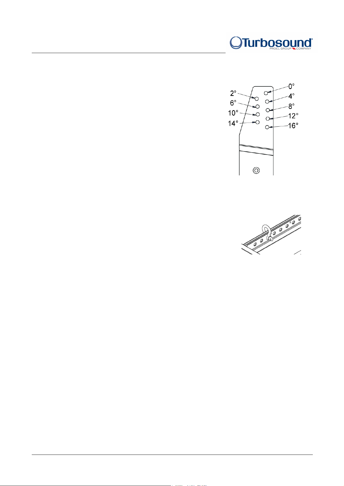
Setting the angle between cabinets
Precise adjustment of inter-cabinet angle is achieved by selecting one of nine
possible engagement positions of the rear flyplates, giving a range of angles
between 0° and 16° in 2° increments.
Rigging an Array of up to 16 cabinets with the FB-1061 flybar
1. Select a suitable pick up point on the flying grid, and choose the inter-cabinet angles to achieve the desired
array angle.
2. Attach the external rigging or motor to the chosen pick up point on the central
spine of the flying grid, using a shackle rated at one tonne or greater. The
shackle eyes must be at least 26mm apart to fit correctly onto the spine.
3. It is suggested to pre-assemble the cabinets in modules of two or three units,
setting the pre-determined inter-cabinet angle as you go. Then attach the first
module to the flying grid, and raise the array to allow a second module to be attached underneath. Repeat for
the remaining modules, and raise the array into position using appropriate lifting equipment.
4. When attaching to static array positions the suggested method is to pre-assemble the entire array including
the flying grid, and lift it into position using appropriate lifting equipment.
Turbosound Ltd, Star Road, Partridge Green, West Sussex RH13 8RY
t: +44 (0)1403 711447 f: +44 (0)1403 710155 w: www.turbosound.com
TCS series Quickstart Guide v1.0 - Page - 6
 Loading...