


LMS-D24

LMS-D24 / LMS-D26
DIGITAL LOUDSPEAKER
MANAGEMENT SYSTEM
USER MANUAL
Turbosound Ltd.
Star Road, Partridge Green
West Sussex RH13 8RY England
Tel: +44 (0)1403 711447 Fax: +44 (0)1403 710155
web: www.turbosound.com
Version 1.0 ©Turbosound 4/05

user manual
LMS-D24/26
LMS-D2X user manual
Page 2
QUICK REFERENCE
(LMS-D26 shown)
Display
The LCD displays preset and parameter information. At start up the display shows the default
screen with the memory location and name of the current preset on the lower line of text.
Channel Select Buttons
The currently selected input or output channel is shown in the top left corner of the display.
Pressing the channel select buttons scrolls through the available inputs and outputs. If operating
stereo linked the channel name will indicate the channel association. For example ‘CH A+B’ means
both input A and B parameters.
Edit Select Buttons
The name of the edit parameter is displayed in the bottom left portion of the LCD. Pressing the edit
select buttons moves through the available parameters for the current input or output.
Parameter Encoders
Up to three parameters are shown on the display. The parameter name is shown with its’ current
value below. Where appropriate parameters are grouped according to function for example centre
frequency, width and gain for parametric EQ. Turn an encoder clockwise to increase the value of a
parameter, or anti-clockwise to decrease it. Turning a knob rapidly will cause the action to
‘accelerate’, so the value changes more rapidly.
Mute Buttons
The LED’s next to the mute buttons indicate their current status. Pressing a mute button toggles
between the mute on and off.
Store Button
The unit has 45 memory locations and allows users to set up their own programs. To store a
preset in a location, press the store button and use the encoders to select the memory location and
name the preset. Pressing the store button again completes the task. Pressing any button other
than store during the process cancels the procedure.

user manual
LMS-D24/26
LMS-D2X user manual
Page 3
CONTENTS
Quick reference ........................................................................................................................................................ 2
Display .................................................................................................................................................................. 2
Channel Select Buttons ...................................................................................................................................... 2
Edit Select Buttons .............................................................................................................................................. 2
Parameter Encoders............................................................................................................................................ 2
Mute Buttons ....................................................................................................................................................... 2
Store Button ......................................................................................................................................................... 2
Important Safety Information................................................................................................................................. 5
Regulatory Compliance ......................................................................................................................................5
Thanks .................................................................................................................................................................. 6
Unpacking the controller ....................................................................................................................................6
Introduction.......................................................................................................................................................... 7
Features................................................................................................................................................................ 7
The User Guide ........................................................................................................................................................ 8
Front Panel Functions ......................................................................................................................................... 9
Rear Panel Functions ........................................................................................................................................11
Operating the LMS series controller.................................................................................................................... 12
Starting up ......................................................................................................................................................... 12
Selecting a Factory Preset ................................................................................................................................12
Creating a Crossover ........................................................................................................................................ 12
Navigation and Viewing Parameters ..............................................................................................................13
Navigation .......................................................................................................................................................... 14
Presets ................................................................................................................................................................15
Preset Recall....................................................................................................................................................... 15
Preset Store........................................................................................................................................................ 16
DSP Processing Layout .........................................................................................................................................17
Input DSP block diagram..................................................................................................................................17
Output DSP block diagram............................................................................................................................... 17
Stereo / Mono Formats..................................................................................................................................... 17
DSP processing ...................................................................................................................................................... 18
Input Channels................................................................................................................................................... 18
Parametric Equalisation.................................................................................................................................... 20
High and Low shelving filters ..........................................................................................................................20
Parametric filters ............................................................................................................................................... 20
Output Channels ....................................................................................................................................................21
Gain and Polarity ............................................................................................................................................... 21
Delay ...................................................................................................................................................................21
High and Low Pass Filters ................................................................................................................................22

user manual
LMS-D24/26
LMS-D2X user manual
Page 4
Parametric Equalisation ................................................................................................................................... 23
Limiters............................................................................................................................................................... 24
Routing ............................................................................................................................................................... 24
Utilities .................................................................................................................................................................... 25
Utility functions ................................................................................................................................................. 25
Factory Presets....................................................................................................................................................... 26
EQ and Filter Response Graphs ........................................................................................................................... 27
Technical Specifications................................................................................................................................... 30
Warranty .................................................................................................................................................................31
NOTES ................................................................................................................................................................ 32

user manual
LMS-D24/26
LMS-D2X user manual
Page 5
IMPORTANT SAFETY INFORMATION
Please read carefully and keep the following instructions and safety information. Heed all warnings
and follow all instructions.
• Do not remove covers. There are no user serviceable parts inside, please refer servicing
to qualified service personnel.
• This equipment must be earthed.
• Protect the power cord from being walked on or pinched particularly at plugs,
convenience receptacles, and the point where they exit from the apparatus.
• Only use attachments/accessories specified by the manufacturer.
• Servicing is required when the apparatus has been damaged in any way, such as the
power supply cord or plug is damaged, liquid has been spilled or objects have fallen into
he apparatus, the apparatus has been exposed to rain or moisture, does not operate
normally, or has been dropped.
Regulatory Compliance
This product complies with both the EMC Directive (89/336/EEC) and the Low Voltage Directive
(73/23/EEC) as issued by the Commission of the European Community.
Compliance with these directives imply conformity with the following European standards:
• EN60065 Product safety
• EN55103-1 Electromagnetic Interference (Emission)
• EN55103-2 Electromagnetic Susceptibility (Immunity)
This product is intended for operation in the E2 (commercial & light industrial) and E3 (urban
outdoors) Electromagnetic Environments.

user manual
LMS-D24/26
LMS-D2X user manual
Page 6
Thanks
Thank you for choosing a TURBOSOUND LMS series controller for your application. Please spare a
little time to read the contents of this manual, so that you obtain the best possible performance
from this unit.
All TURBOSOUND products are carefully engineered for world class performance and reliability.
If you would like further information about this or any other TURBOSOUND product, please
contact us.
We look forward to helping you in the near future.
Unpacking the controller
After unpacking the unit please check carefully for damage. If damage is found, please notify the
carrier concerned at once. You, the consignee, must instigate any claim. Please retain all
packaging in case of future re-shipment.

user manual
LMS-D24/26
LMS-D2X user manual
Page 7
Introduction
The Turbosound LMS series of loudspeaker management systems represents the current state-of-
the-art in digital electronics. The LMS-D24/26 are compact and powerful DSP based audio-
processing units designed for use with Turbosound loudspeaker systems and associated bass
enclosures, combining the functions of multiple conventional products in a compact 1U high 19”
rack unit. To achieve this the LMS-D26 has 2 inputs and 6 outputs (the LMS-D24 features four
outputs), which are configured by different factory presets to allow use with a variety of systems.
The units are designed to provide specific equalisation and crossover points aimed at optimising
the performance of these Turbosound loudspeaker systems. In addition, limiters, delays eq, gain,
polarity, and crossover filter controls are accessible to the user in order to match specific operation
environments. The LMS series crossovers are designed for quick setup and adjustment via easy-to-
use front panel controls.
Features
• Minimal signal path design, providing exceptional audio quality with carefully optimised
processing and high performance converters for a full >111dB dynamic range, 96kHz
sampling rate and minimal filtering. Audio-grade capacitors are used in the analogue signal
path.
• Sonically superb ADC / DAC combination; a carefully matched pairing of the best devices
from Burr Brown and Wolfson.
• Newly released family of Analogue Devices SHARC DSP.
• Extended bandwidth; 96kHz sampling frequency provides for a nominally flat response to
40kHz.
• Front panel parameter rotary encoder provides a familiar and easy to use control format
with all filter information displayed simultaneously on a backlit LCD display.

user manual
LMS-D24/26
LMS-D2X user manual
Page 8
THE USER GUIDE
This user manual gives a progressively more detailed description of the functions of the
TURBOSOUND LMS-D26 and LMS-D24 loudspeaker management systems. A single page quick
reference guide is provided for those users who are experienced with this type of equipment and
just need to know how to ‘drive’ the front panel.
A detailed explanation of the front and rear panel controls and indicators is contained in the next
section. The final section describes each individual function or feature with annotated images
explaining its use. Where appropriate, the LCD is shown to further elaborate on the unit’s
operation.
To complete the manual a reference section is included, describing the technical performance of
the device complete with graphs of filter responses and details of the
Factory Presets
and their
configuration.
user manual
LMS-D24/26
LMS-D2X user manual
Page 9
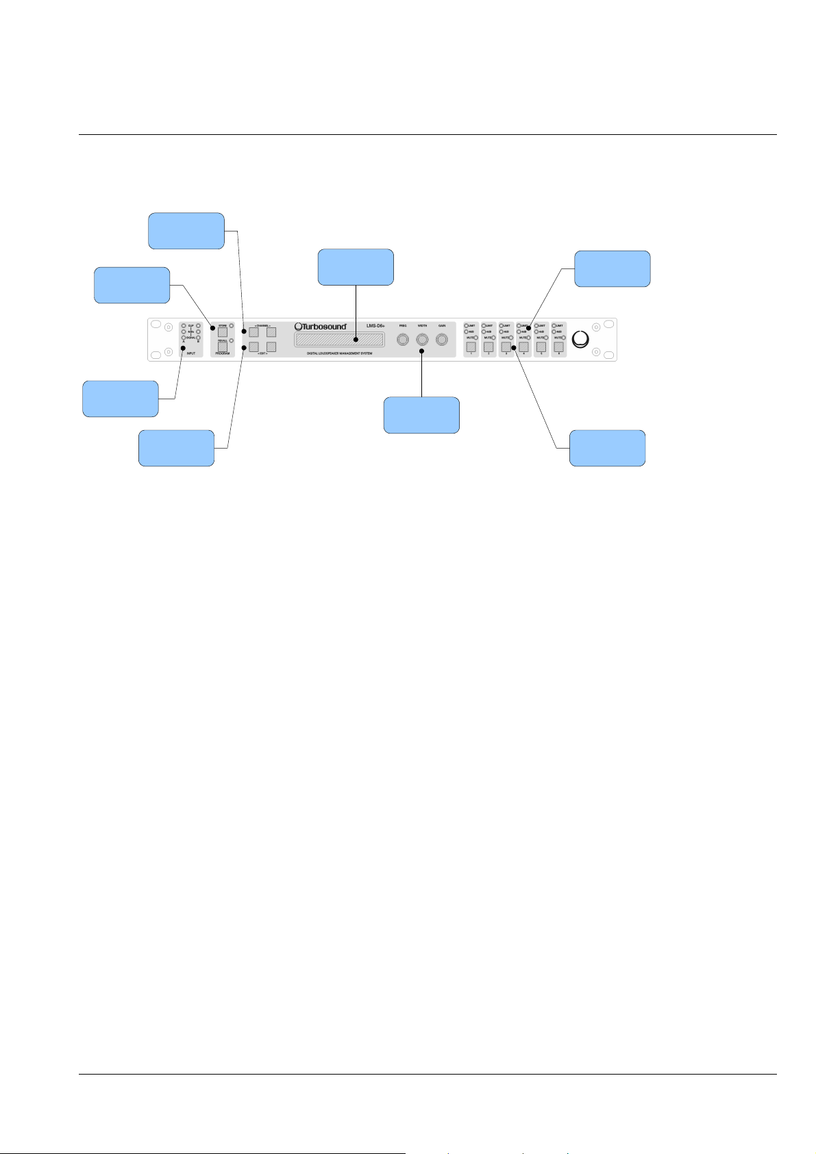
Front Panel Functions
2x 24 character
LCD
Input Signal
Indicators
Store and
Recall butto ns
Channel Select
buttons
Parameter Edit
Encoders
Output Mute
buttons
Limiter
Indicators
Edit Parameter
Select buttons
• Input Signal Indicators – A set of three pairs of LED’s indicate signal present, +4dBu and
input clip for both channels. The signal present LED’s operate at approximately –40 dBu,
giving a useful indication of even relatively low input signal levels. The +4 dBu LED’s are
intended to show nominal operating level and can also be useful for setting system gain
structure. Clip LED’s warn the user of input overload and operate at +19 dBu.
• Program Store and Recall – these controls provide access to 45 presets. Pressing the
store button allows the user to name a preset and choose which memory location it will
be held in. Pressing store button again completes the process. The Recall function
operates in a similar way, pressing the recall button allows the user to select which preset
they require, pressing the button for a second time, then confirming, recalls the new DSP
settings. The unit allows the user to set up user programs with full access to all
parameters.
Note that presets cannot be stored or recal l ed w hen secur e mode i s act ivated.
• Channel Selection Buttons – the currently selected channel is displayed on the top left
hand corner of the LCD. Pressing the channel buttons scrolls through the available input
and output channels and finally through the utility functions and back to the default
screen. If operating a stereo-linked preset the channel name will indicate the channel
pairing. For example ‘A+B’ means both input A and B parameters. The name of the output
will be shown briefly at the top of the display when stepping onto an output.

user manual
LMS-D24/26
LMS-D2X user manual
Page 10
• Edit Select Buttons – the currently selected edit parameter is displayed on the bottom left
corner of the LCD. Pressing the edit select buttons moves through the available
parameters for the current input or output.
• Text display – preset, channel, parameter and status information is shown on the 2x 24-
character text display. In most screens the currently selected channel is displayed on the
upper line and the edit parameter on the lower line. To simplify the display and enhance
security, some parameters or parameter pages are omitted when not relevant.
• Parameter Knobs – three velocity sensitive parameter knobs are used to adjust
parameters shown on the display. Up to three parameters are displayed on the screen.
The parameter name is shown above the parameter value in each of the three screen
sections. The parameter knobs have a fixed association with the screen sections; the
rightmost parameter knob adjusts the rightmost parameter and so on.
• Output signal and limiter indication – two LED’s are provided for each output channel.
These show the signal level relative to the limiter threshold. The yellow LED will light
when the signal is 6dB below the threshold and the red warning LED will light when the
limiter threshold is reached.
• Mute buttons and status LED’s – each output has a mute button and associated mute
status LED. Pressing the button toggles the mute on and off.
•
Note that the mute buttons do not funct ion when the Secure Mode is activated.
• Secure Button (on the rear) – a momentary button is fitted behind the rear panel,
between the output XLRs and the RS232 port. When activated, this will disable all the
front panel controls so they cannot affect the signal path, making the unit secure against
tampering. When in secure mode, the indicators still operate normally.
Note that the communications port is still active in secure mode.
 Loading...