

Page 1
Quick Start Guide
iQ Series
2500 Watt 2 Way 8"/10"/12"/15" Powered Loudspeaker 3000 Watt 15"/18" Powered Subwoofer
KLARK TEKNIK DSP Technology, Speaker Modelling and ULTRANET Networking
Page 2
2 iQ Series Quick Start Guide 3
Important Safety
Instructions
LEGAL DISCLAIMER
Instrucciones de
seguridad
NEGACIÓN LEGAL
GARANTÍA LIMITADA
LIMITED WARRANTY
Terminals marked with this symbol carry
electrical current of sucient magnitude
to constitute risk of electric shock.
Use only high-quality professional speaker cables with
¼" TS or twist-locking plugs pre-installed. Allother
installation or modication should be performed only
by qualiedpersonnel.
This symbol, wherever it appears,
alertsyou to the presence of uninsulated
dangerous voltage inside the
enclosure-voltage that may be sucient to constitute a
risk ofshock.
This symbol, wherever it appears,
alertsyou to important operating and
maintenance instructions in the
accompanying literature. Please read the manual.
Caution
To reduce the risk of electric shock, donot
remove the top cover (or the rear section).
No user serviceable parts inside. Refer servicing to
qualied personnel.
Caution
To reduce the risk of re or electric shock,
do not expose this appliance to rain and
moisture. The apparatus shall not be exposed to dripping
or splashing liquids and no objects lled with liquids,
suchas vases, shall be placed on the apparatus.
Caution
These service instructions are for use
by qualied service personnel only.
Toreduce the risk of electric shock do not perform any
servicing other than that contained in the operation
instructions. Repairs have to be performed by qualied
servicepersonnel.
1. Read these instructions.
2. Keep these instructions.
3. Heed all warnings.
4. Follow all instructions.
5. Do not use this apparatus near water.
6. Clean only with dry cloth.
7. Do not block any ventilation openings. Install in
accordance with the manufacturer’s instructions.
8. Do not install near any heat sources such as
radiators, heat registers, stoves, or other apparatus
(including ampliers) that produce heat.
9. Do not defeat the safety purpose of the polarized
or grounding-type plug. A polarized plug has two blades
with one wider than the other. A grounding-type plug
has two blades and a third grounding prong. The wide
blade or the third prong are provided for your safety. Ifthe
provided plug does not t into your outlet, consult an
electrician for replacement of the obsolete outlet.
10. Protect the power cord from being walked on or
pinched particularly at plugs, convenience receptacles,
and the point where they exit from the apparatus.
11. Use only attachments/accessories specied by
themanufacturer.
12. Use only with the
cart, stand, tripod, bracket,
or table specied by the
manufacturer, orsold with
the apparatus. When a cart
is used, use caution when
moving the cart/apparatus
combination to avoid
injury from tip-over.
13. Unplug this apparatus during lightning storms or
when unused for long periods of time.
14. Refer all servicing to qualied service personnel.
Servicing is required when the apparatus has been
damaged in any way, such as power supply cord or plug
is damaged, liquid has been spilled or objects have fallen
into the apparatus, the apparatus has been exposed
to rain or moisture, does not operate normally, or has
beendropped.
15. The apparatus shall be connected to a MAINS socket
outlet with a protective earthing connection.
16. Where the MAINS plug or an appliance coupler is
used as the disconnect device, the disconnect device shall
remain readily operable.
17. Correct disposal of this
product: This symbol indicates that
this product must not be disposed
of with household waste,
according to the WEEE Directive
(2012/19/EU) and your national
law. This product should be taken
to a collection center licensed for the recycling of waste
electrical and electronic equipment (EEE). The
mishandling of this type of waste could have a possible
negative impact on the environment and human health
due to potentially hazardous substances that are generally
associated with EEE. At the same time, your cooperation
in the correct disposal of this product will contribute to
the ecient use of natural resources. For more
information about where you can take your waste
equipment for recycling, please contact your local city
oce, or your household waste collection service.
18. Do not install in a conned space, such as a book
case or similar unit.
19. Do not place naked ame sources, such as lighted
candles, on the apparatus.
20. Please keep the environmental aspects of battery
disposal in mind. Batteries must be disposed-of at a
battery collection point.
21. Use this apparatus in tropical and/or
moderate climates.
MUSIC Tribe accepts no liability for any loss which
may be suered by any person who relies either
wholly or in part upon any description, photograph,
or statement contained herein. Technical specications,
appearances and other information are subject to
change without notice. All trademarks are the property
of their respective owners. MIDAS, KLARK TEKNIK,
LAB GRUPPEN, LAKE, TANNOY, TURBOSOUND,
TC ELECTRONIC, TC HELICON, BEHRINGER, BUGERA and
COOLAUDIO are trademarks or registered trademarks
of MUSIC Tribe Global Brands Ltd. © MUSIC Tribe Global
Brands Ltd. 2018 All rights reserved.
For the applicable warranty terms and conditions
and additional information regarding MUSIC Tribe’s
Limited Warranty, please see complete details online at
musictri.be/warranty.
Las terminales marcadas con este símbolo
transportan corriente eléctrica de
magnitud suciente como para constituir
un riesgo de descarga eléctrica. Utilice solo cables de
altavoz profesionales y de alta calidad con conectores
TS de 6,3 mm o de bayoneta prejados. Cualquier otra
instalación o modicación debe ser realizada únicamente
por un técnico cualicado.
Este símbolo, siempre que aparece,
leadvierte de la presencia de voltaje
peligroso sin aislar dentro de la caja;
estevoltaje puede ser suciente para constituir un riesgo
dedescarga.
Este símbolo, siempre que aparece,
leadvierte sobre instrucciones operativas
y de mantenimiento que aparecen en la
documentación adjunta. Por favor, lea el manual.
Atención
Para reducir el riesgo de descarga
eléctrica, no quite la tapa (o la parte
posterior). No hay piezas en el interior del equipo que
puedan ser reparadas por el usuario. Si es necesario,
póngase en contacto con personal cualicado.
Atención
Para reducir el riesgo de incendio o
descarga eléctrica, no exponga este
aparato a la lluvia, humedad o alguna otra fuente que
pueda salpicar o derramar algún líquido sobre el aparato.
Nocoloque ningún tipo de recipiente para líquidos sobre
el aparato.
Atención
Las instrucciones de servicio deben
llevarlas a cabo exclusivamente personal
cualicado. Para evitar el riesgo de una descarga eléctrica,
no realice reparaciones que no se encuentren descritas
en el manual de operaciones. Lasreparaciones deben ser
realizadas exclusivamente por personalcualicado.
1. Lea las instrucciones.
2. Conserve estas instrucciones.
3. Preste atención a todas las advertencias.
4. Siga todas las instrucciones.
5. No use este aparato cerca del agua.
6. Limpie este aparato con un paño seco.
7. No bloquee las aberturas de ventilación. Instale el
equipo de acuerdo con las instrucciones del fabricante.
8. No instale este equipo cerca de fuentes de calor
tales como radiadores, acumuladores de calor, estufas u
otros aparatos (incluyendo amplicadores) que puedan
producir calor.
9. No elimine o deshabilite nunca la conexión a tierra
del aparato o del cable de alimentación de corriente.
Unenchufe polarizado tiene dos polos, uno de los cuales
tiene un contacto más ancho que el otro. Una clavija con
puesta a tierra dispone de tres contactos: dos polos y la
puesta a tierra. El contacto ancho y el tercer contacto,
respectivamente, son los que garantizan una mayor
seguridad. Si el enchufe suministrado con el equipo no
concuerda con la toma de corriente, consulte con un
electricista para cambiar la toma de corriente obsoleta.
10. Coloque el cable de suministro de energía de manera
que no pueda ser pisado y que esté protegido de objetos
alados. Asegúrese de que el cable de suministro de
energía esté protegido, especialmente en la zona de la
clavija y en el punto donde sale del aparato.
11. Use únicamente los dispositivos o accesorios
especicados por el fabricante.
12. Use únicamente la
carretilla, plataforma,
trípode, soporte o mesa
especicados por el
fabricante o suministrados
junto con el equipo.
Altransportar el equipo,
tenga cuidado para evitar
daños y caídas al tropezar con algún obstáculo.
13. Desenchufe el equipo durante tormentas o si no va a
utilizarlo durante un periodo largo.
14. Confíe las reparaciones únicamente a servicios
técnicos cualicados. La unidad requiere mantenimiento
siempre que haya sufrido algún daño, si el cable de
suministro de energía o el enchufe presentaran daños,
sehubiera derramado un líquido o hubieran caído objetos
dentro del equipo, si el aparato hubiera estado expuesto
a la humedad o la lluvia, si ha dejado de funcionar de
manera normal o si ha sufrido algún golpe o caída.
15. Al conectar la unidad a la toma de corriente eléctrica
asegúrese de que la conexión disponga de una unión
atierra.
16. Si el enchufe o conector de red sirve como único
medio de desconexión, éste debe ser accesiblefácilmente.
17. Cómo debe deshacerse de
este aparato: Este símbolo indica
que este aparato no debe ser
tratado como basura orgánica,
según lo indicado en la Directiva
WEEE (2012/19/EU) y a las
normativas aplicables en su país.
En lugar de ello deberá llevarlo al punto limpio más
cercano para el reciclaje de sus elementos eléctricos/
electrónicos (EEE). Al hacer esto estará ayudando a
prevenir las posibles consecuencias negativas para el
medio ambiente y la salud que podrían ser provocadas por
una gestión inadecuada de este tipo de aparatos. Además,
el reciclaje de materiales ayudará a conservar los recursos
naturales. Para más información acerca del reciclaje de
este aparato, póngase en contacto con el Ayuntamiento
de su ciudad o con el punto limpio local.
18. No instale esta unidad en un espacio muy reducido,
tal como encastrada en una librería o similar.
19. No coloque objetos con llama, como una vela
encendida, sobre este aparato.
20. Tenga presentes todas las advertencias relativas
al reciclaje y correcta eliminación de las pilas. Las pilas
deben ser siempre eliminadas en un punto limpio y nunca
con el resto de la basura orgánica.
21. Use este aparato en rangos de temperatura
moderados y/o tropicales.
MUSIC Tribe no admite ningún tipo de responsabilidad
por cualquier daño o pérdida que pudiera sufrir
cualquier persona por conar total o parcialmente
en la descripciones, fotografías o armaciones
contenidas en este documento. Las especicaciones
técnicas, imágenes y otras informaciones contenidas
en este documento están sujetas a modicaciones
sin previo aviso. Todas las marcas comerciales que
aparecen aquí son propiedad de sus respectivos
dueños. MIDAS, KLARK TEKNIK, LAB GRUPPEN,
LAKE, TANNOY, TURBOSOUND, TC ELECTRONIC,
TC HELICON, BEHRINGER, BUGERA y COOLAUDIO
son marcas comerciales o marcas registradas de
MUSIC Tribe Global Brands Ltd. © MUSIC Tribe Global
Brands Ltd. 2018 Reservados todos los derechos.
Si quiere conocer los detalles y condiciones aplicables
de la garantía así como información adicional sobre la
Garantía limitada de MUSIC Tribe, consulte online toda la
información en la web musictri.be/warranty.
Page 3
4 iQ Series Quick Start Guide 5
Consignes de sécurité
DÉNI LÉGAL
GARANTIE LIMITÉE
Wichtige
Sicherheitshinweise
HAFTUNGSAUSSCHLUSS
BESCHRÄNKTE GARANTIE
Les points repérés par ce symbole portent
une tension électrique susante pour
constituer un risque d’électrocution.
Utilisez uniquement des câbles d’enceintes professionnels
de haute qualité avec ches Jack mono 6,35 mm ou ches
à verrouillages déjà installées. Touteautre installation ou
modication doit être eectuée uniquement par un
personnel qualié.
Ce symbole avertit de la présence d’une
tension dangereuse et non isolée à
l’intérieur de l’appareil - elle peut
provoquer des chocs électriques.
Attention
Ce symbol signale les consignes
d’utilisation et d’entre ! Tien importantes
dans la documentation fournie. Lisez les consignes de
sécurité du manuel d’utilisation de l’appareil.
Attention
Pour éviter tout risque de choc électrique,
ne pas ouvrir le capot de l’appareil ni
démonter le panneau arrière. L’intérieur de l’appareil
ne possède aucun élément réparable par l’utilisateur.
Laissertoute réparation à un professionnel qualié.
Attention
Pour réduire les risques de feu et de choc
électrique, n’exposez pas cet appareil à la
pluie, à la moisissure, aux gouttes ou aux éclaboussures.
Ne posez pas de récipient contenant un liquide sur
l’appareil (un vase par exemple).
Attention
Ces consignes de sécurité et d’entretien
sont destinées à un personnel qualié.
Pouréviter tout risque de choc électrique, n’eectuez
aucune réparation sur l’appareil qui ne soit décrite par le
manuel d’utilisation. Les éventuelles réparations doivent
être eectuées uniquement par un technicien spécialisé.
1. Lisez ces consignes.
2. Conservez ces consignes.
3. Respectez tous les avertissements.
4. Respectez toutes les consignes d’utilisation.
5. N’utilisez jamais l’appareil à proximité d’un liquide.
6. Nettoyez l’appareil avec un chion sec.
7. Veillez à ne pas empêcher la bonne ventilation de
l’appareil via ses ouïes de ventilation. Respectezles
consignes du fabricant concernant l’installation
del’appareil.
8. Ne placez pas l’appareil à proximité d’une source
de chaleur telle qu’un chauage, une cuisinière ou tout
appareil dégageant de la chaleur (y compris un ampli
depuissance).
9. Ne supprimez jamais la sécurité des prises bipolaires
ou des prises terre. Les prises bipolaires possèdent deux
contacts de largeur diérente. Leplus large est le contact
de sécurité. Les prises terre possèdent deux contacts plus
une mise à la terre servant de sécurité. Si la prise du bloc
d’alimentation ou du cordon d’ali-mentation fourni ne
correspond pas à celles de votre installation électrique,
faites appel à un électricien pour eectuer le changement
de prise.
10. Installez le cordon d’alimentation de telle façon
que personne ne puisse marcher dessus et qu’il soit
protégé d’arêtes coupantes. Assurez-vous que le cordon
d’alimentation est sufsamment protégé, notamment au
niveau de sa prise électrique et de l’endroit où il est relié à
l’appareil; cela est également valable pour une éventuelle
rallonge électrique.
11. Utilisez exclusivement des accessoires et des
appareils supplémentaires recommandés par lefabricant.
12. Utilisez
exclusivement des
chariots, des diables,
desprésentoirs, despieds
et des surfaces de
travail recommandés
par le fabricant ou
livrés avec le produit.
Déplacezprécautionneusement tout chariot ou diable
chargé pour éviter d’éventuelles blessures en cas dechute.
13. Débranchez l’appareil de la tension secteur en cas
d’orage ou si l’appareil reste inutilisé pendant une longue
période de temps.
14. Les travaux d’entretien de l’appareil doivent
être eectués uniquement par du personnel qualié.
Aucunentretien n’est nécessaire sauf si l’appareil est
endommagé de quelque façon que ce soit (dommagessur
le cordon d’alimentation ou la prise par exemple), siun
liquide ou un objet a pénétré à l’intérieur du châssis,
si l’appareil a été exposé à la pluie ou à l’humidité, s’il ne
fonctionne pas correctement ou à la suite d’une chute.
15. L’appareil doit être connecté à une prise secteur
dotée d’une protection par mise à la terre.
16. La prise électrique ou la prise IEC de tout appareil
dénué de bouton marche/arrêt doit rester accessible
enpermanence.
17. Mise au rebut appropriée de
ce produit: Ce symbole indique
qu’en accord avec la directive DEEE
(2012/19/EU) et les lois en vigueur
dans votre pays, ce produit ne doit
pas être jeté avec les déchets
ménagers. Ce produit doit être
déposé dans un point de collecte agréé pour le recyclage
des déchets d’équipements électriques et électroniques
(EEE). Une mauvaise manipulation de ce type de déchets
pourrait avoir un impact négatif sur l’environnement et la
santé à cause des substances potentiellement
dangereuses généralement associées à ces équipements.
En même temps, votre coopération dans la mise au rebut
de ce produit contribuera à l’utilisation ecace des
ressources naturelles. Pour plus d’informations sur
l’endroit où vous pouvez déposer vos déchets
d’équipements pour le recyclage, veuillez contacter votre
mairie ou votre centre local de collecte des déchets.
18. N’installez pas l’appareil dans un espace conné tel
qu’une bibliothèque ou meuble similaire.
19. Ne placez jamais d’objets enammés, tels que des
bougies allumées, sur l’appareil.
20. Gardez à l’esprit l’impact environnemental lorsque
vous mettez des piles au rebus. Les piles usées doivent
être déposées dans un point de collecte adapté.
21. Utilisez l’appareil dans un climat tropical
et/ou modéré.
MUSIC Tribe ne peut être tenu pour responsable pour
toute perte pouvant être subie par toute personne
se ant en partie ou en totalité à toute description,
photographie ou armation contenue dans ce
document. Les caractéristiques, l’apparence et d’autres
informations peuvent faire l’objet de modications
sans notication. Toutes les marques appartiennent à
leurs propriétaires respectifs. MIDAS, KL ARK TEKNIK,
LAB GRUPPEN, LAKE, TANNOY, TURBOSOUND,
TC ELECTRONIC, TC HELICON, BEHRINGER, BUGERA et
COOLAUDIO sont des marques ou marques déposées de
MUSIC Tribe Global Brands Ltd. © MUSIC Tribe Global
Brands Ltd. 2018 Tous droits réservés.
Pour connaître les termes et conditions de garantie
applicables, ainsi que les informations supplémentaires
et détaillées sur la Garantie Limitée de MUSIC Tribe,
consultez le site Internet musictri.be/warranty.
Vorsicht
Die mit dem Symbol markierten
Anschlüsse führen so viel Spannung,
dassdie Gefahr eines Stromschlags besteht.
Verwenden Sie nur hochwertige, professionelle
Lautsprecherkabel mit vorinstallierten 6,35 mm
MONO-Klinkensteckern oder Lautsprecherstecker
mit Drehverriegelung. Alle anderen Installationen
oder Modikationen sollten nur von qualiziertem
Fachpersonal ausgeführt werden.
Achtung
Um eine Gefährdung durch Stromschlag
auszuschließen, darf die Geräteabdeckung
bzw. Geräterückwand nicht abgenommen werden.
ImInnern des Geräts benden sich keine vom Benutzer
reparierbaren Teile. Reparaturarbeiten dürfen nur von
qualiziertem Personal ausgeführt werden.
Achtung
Um eine Gefährdung durch Feuer bzw.
Stromschlag auszuschließen, darf dieses
Gerät weder Regen oder Feuchtigkeit ausgesetzt werden
noch sollten Spritzwasser oder tropfende Flüssigkeiten
in das Gerät gelangen können. Stellen Sie keine mit
Flüssigkeit gefüllten Gegenstände, wie z. B. Vasen,
aufdasGerät.
Achtung
Die Service-Hinweise sind nur durch
qualiziertes Personal zu befolgen.
Umeine Gefährdung durch Stromschlag zu vermeiden,
führen Sie bitte keinerlei Reparaturen an dem Gerät
durch, die nicht in der Bedienungsanleitung beschrieben
sind. Reparaturen sind nur von qualiziertem
Fachpersonaldurchzuführen.
1. Lesen Sie diese Hinweise.
2. Bewahren Sie diese Hinweise auf.
3. Beachten Sie alle Warnhinweise.
4. Befolgen Sie alle Bedienungshinweise.
5. Betreiben Sie das Gerät nicht in der Nähe vonWasser.
6. Reinigen Sie das Gerät mit einem trockenen Tuch.
7. Blockieren Sie nicht die Belüftungsschlitze. Beachten
Sie beim Einbau des Gerätes die Herstellerhinweise.
8. Stellen Sie das Gerät nicht in der Nähe von
Wärmequellen auf. Solche Wärmequellen sind z. B.
Heizkörper, Herde oder andere Wärme erzeugende Geräte
(auch Verstärker).
9. Entfernen Sie in keinem Fall die
Sicherheitsvorrichtung von Zweipol- oder geerdeten
Steckern. Ein Zweipolstecker hat zwei unterschiedlich
breite Steckkontakte. Ein geerdeter Stecker hat zwei
Steckkontakte und einen dritten Erdungskontakt.
Derbreitere Steckkontakt oder der zusätzliche
Erdungskontakt dient Ihrer Sicherheit. Falls das
mitgelieferte Steckerformat nicht zu Ihrer Steckdose
passt, wenden Sie sich bitte an einen Elektriker, damit die
Steckdose entsprechend ausgetauscht wird.
10. Verlegen Sie das Netzkabel so, dass es vor
Tritten und scharfen Kanten geschützt ist und nicht
beschädigt werden kann. Achten Sie bitte insbesondere
im Bereich der Stecker, Verlängerungskabel und an
der Stelle, an der das Netzkabel das Gerät verlässt,
aufausreichendenSchutz.
11. Das Gerät muss jederzeit mit intaktem Schutzleiter
an das Stromnetz angeschlossen sein.
12. Sollte der Hauptnetzstecker oder eine
Gerätesteckdose die Funktionseinheit zum Abschalten
sein, muss diese immer zugänglich sein.
13. Verwenden Sie nur Zusatzgeräte/Zubehörteile,
dielaut Hersteller geeignet sind.
14. Verwenden
Sie nur Wagen,
Standvorrichtungen,
Stative, Halter oder Tische,
die vom Hersteller benannt
oder im Lieferumfang
des Geräts enthalten
sind. Falls Sie einen
Wagen benutzen, seien Sie vorsichtig beim Bewegen
der Wagen- Gerätkombination, umVerletzungen durch
Stolpern zuvermeiden.
15. Ziehen Sie den Netzstecker bei Gewitter oder wenn
Sie das Gerät längere Zeit nicht benutzen.
16. Lassen Sie alle Wartungsarbeiten nur von
qualiziertem Service-Personal ausführen. EineWartung
ist notwendig, wenn das Gerät in irgendeiner Weise
beschädigt wurde (z. B. Beschädigung des Netzkabels oder
Steckers), Gegenstände oder Flüssigkeit in das Geräteinnere
gelangt sind, das Gerät Regen oder Feuchtigkeit ausgesetzt
wurde, das Gerät nicht ordnungsgemäß funktioniert oder
auf den Boden gefallen ist.
17. Korrekte Entsorgung dieses
Produkts: Dieses Symbol weist
darauf hin, das Produkt
entsprechend der WEEE Direktive
(2012/19/EU) und der jeweiligen
nationalen Gesetze nicht
zusammen mit Ihren
Haushaltsabfällen zu entsorgen. DiesesProdukt sollte bei
einer autorisierten Sammelstelle für Recycling elektrischer
und elektronischer Geräte (EEE) abgegeben werden.
Wegen bedenklicher Substanzen, diegenerell mit
elektrischen und elektronischen Geräten in Verbindung
stehen, könnte eine unsachgemäße Behandlung dieser
Abfallart eine negative Auswirkung auf Umwelt und
Gesundheit haben. Gleichzeitig gewährleistet Ihr Beitrag
zur richtigen Entsorgung dieses Produkts die eektive
Nutzung natürlicher Ressourcen. Fürweitere
Informationen zur Entsorgung Ihrer Geräte bei einer
Recycling-Stelle nehmen Sie bitte Kontakt zum
zuständigen städtischen Büro, Entsorgungsamt oder zu
Ihrem Haushaltsabfallentsorgerauf.
18. Installieren Sie das Gerät nicht in einer beengten
Umgebung, zum Beispiel Bücherregal oder ähnliches.
19. Stellen Sie keine Gegenstände mit oenen
Flammen, etwa brennende Kerzen, auf das Gerät.
20. Beachten Sie bei der Entsorgung von Batterien
den Umweltschutz-Aspekt. Batterien müssen bei einer
Batterie-Sammelstelle entsorgt werden.
21. Verwenden Sie das Gerät in tropischen und/oder
gemäßigten Klimazonen.
MUSIC Tribe übernimmt keine Haftung für Verluste,
die Personen entstanden sind, die sich ganz oder
teilweise auf hier enthaltene Beschreibungen,
Fotos oder Aussagen verlassen haben. Technische Daten,
Erscheinungsbild und andere Informationen können
ohne vorherige Ankündigung geändert werden.
Alle Warenzeichen sind Eigentum der jeweiligen
Inhaber. MIDAS, KLARK TEKNIK, LAB GRUPPEN,
LAKE, TANNOY, TURBOSOUND, TC ELECTRONIC,
TC HELICON, BEHRINGER, BUGERA und COOLAUDIO
sind Warenzeichen oder eingetragene Warenzeichen der
MUSIC Tribe Global Brands Ltd. © MUSIC Tribe Global
Brands Ltd. 2018 Alle Rechte vorbehalten.
Die geltenden Garantiebedingungen und zusätzliche
Informationen bezüglich der von MUSIC Tribe gewähr ten
beschränkten Garantie nden Sie online unter
musictri.be/warranty.
Page 4
6 iQ Series Quick Start Guide 7
Instruções de Segurança
Importantes
LEGAL RENUNCIANTE
GARANTIA LIMITADA
Thank you for choosing a TURBOSOUND loudspeaker produc t for your application. If you would like further information about this or any other TURBOSOUND product,
please visit our website at turbosound.com.
Unpacking the Loudspeaker
After unpacking the unit please check carefully for damage. If damage is found, please notify your supplier at once. You, the consignee, must instigate any claim.
Please retain all packaging in case of futurere-shipment.
Controls
Aviso!
Terminais marcados com o símbolo
carregam corrente elétrica de magnitude
suciente para constituir um risco de choque elétrico.
Use apenas cabos de alto-falantes de alta qualidade
com plugues TS de ¼" ou plugues com trava de torção
pré-instalados. Todas as outras instalações e modicações
devem ser efetuadas por pessoasqualicadas.
Este símbolo, onde quer que o encontre,
alerta-o para a leitura das instruções de
manuseamento que acompanham o
equipamento. Por favor leia o manual de instruções.
Atenção
De forma a diminuir o risco de choque
eléctrico, não remover a cobertura
(ouasecção de trás). Não existem peças substituíveis por
parte do utilizador no seu interior. Para esse efeito recorrer
a um técnico qualicado.
Atenção
Para reduzir o risco de incêndios ou
choques eléctricos o aparelho não deve ser
exposto à chuva nem à humidade. Além disso, não deve
ser sujeito a salpicos, nem devem ser colocados em cima
do aparelho objectos contendo líquidos, tais como jarras.
Atenção
Estas instruções de operação devem ser
utilizadas, em exclusivo, por técnicos de
assistência qualicados. Para evitar choques eléctricos
não proceda a reparações ou intervenções, que não as
indicadas nas instruções de operação, salvo se possuir as
quali-cações necessárias. Para evitar choques eléctricos
não proceda a reparações ou intervenções, que não as
indicadas nas instruções de operação. Só o deverá fazer se
possuir as qualicações necessárias.
1. Leia estas instruções.
2. Guarde estas instruções.
3. Preste atenção a todos os avisos.
4. Siga todas as instruções.
5. Não utilize este dispositivo perto de água.
6. Limpe apenas com um pano seco.
7. Não obstrua as entradas de ventilação. Instale de
acordo com as instruções do fabricante.
8. Não instale perto de quaisquer fontes de calor
tais como radiadores, bocas de ar quente, fogões de
sala ou outros aparelhos (incluindo amplicadores)
que produzam calor.
9. Não anule o objectivo de segurança das chas
polarizadas ou do tipo de ligação à terra. Uma cha
polarizada dispõe de duas palhetas sendo uma mais larga
do que a outra. Uma cha do tipo ligação à terra dispõe
de duas palhetas e um terceiro dente de ligação à terra.
A palheta larga ou o terceiro dente são fornecidos para
sua segurança. Se a cha fornecida não encaixar na sua
tomada, consulte um electricista para a substituição da
tomada obsoleta.
10. Proteja o cabo de alimentação de pisadelas ou
apertos, especialmente nas chas, extensões, e no local
de saída da unidade. Certique-se de que o cabo eléctrico
está protegido. Verique particularmente nas chas, nos
receptáculos e no ponto em que o cabo sai doaparelho.
11. O aparelho tem de estar sempre conectado à rede
eléctrica com o condutor de protecção intacto.
12. Se utilizar uma cha de rede principal ou uma
tomada de aparelhos para desligar a unidade de
funcionamento, esta deve estar sempre acessível.
13. Utilize apenas ligações/acessórios especicados
pelofabricante.
14. Utilize apenas com
o carrinho, estrutura,
tripé, suporte, ou mesa
especicados pelo
fabricante ou vendidos
com o dispositivo.
Quandoutilizar um
carrinho, tenha cuidado ao
mover o conjunto carrinho/dispositivo para evitar danos
provocados pela terpidação.
15. Desligue este dispositivo durante as trovoadas
ou quando não for utilizado durante longos períodos
detempo.
16. Qualquer tipo de reparação deve ser sempre
efectuado por pessoal qualicado. É necessária uma
reparação sempre que a unidade tiver sido de alguma
forma danicada, como por exemplo: no caso do cabo
de alimentação ou cha se encontrarem danicados;
naeventualidade de líquido ter sido derramado ou
objectos terem caído para dentro do dispositivo; no caso
da unidade ter estado exposta à chuva ou à humidade;
seesta não funcionar normalmente, ou se tiver caído.
17. Correcta eliminação deste
produto: este símbolo indica que
o produto não deve ser eliminado
juntamente com os resíduos
domésticos, segundo a Directiva
REEE (2012/19/EU) e a legislação
nacional. Este produto deverá
ser levado para um centro de recolha licenciado para a
reciclagem de resíduos de equipamentos eléctricos e
electrónicos (EEE). O tratamento incorrecto deste tipo
de resíduos pode ter um eventual impacto negativo
no ambiente e na saúde humana devido a substâncias
potencialmente perigosas que estão geralmente
associadas aos EEE. Ao mesmo tempo, a sua colaboração
para a eliminação correcta deste produto irá contribuir
para a utilização eciente dos recursos naturais. Paramais
informação acerca dos locais onde poderá deixar o seu
equipamento usado para reciclagem, é favor contactar
os serviços municipais locais, a entidade de gestão de
resíduos ou os serviços de recolha de resíduosdomésticos.
18. Não instale em lugares connados, tais como
estantes ou unidades similares.
19. Não coloque fontes de chama, tais como velas
acesas, sobre o aparelho.
20. Favor, obedecer os aspectos ambientais de descarte
de bateria. Baterias devem ser descartadas em um ponto
de coletas de baterias.
21. Use este aparelho em climas tropicais
e/ou moderados.
O MUSIC Tribe não se responsabiliza por perda alguma
que possa ser sofrida por qualquer pessoa que dependa,
seja de maneira completa ou parcial, de qualquer
descrição, fotograa, ou declaração aqui contidas.
Dados técnicos, aparências e outras informações
estão sujeitas a modicações sem aviso prévio.
Todas as marcas são propriedade de seus respectivos
donos. MIDAS, KLARK TEKNIK, LAB GRUPPEN,
LAKE, TANNOY, TURBOSOUND, TC ELECTRONIC,
TC HELICON, BEHRINGER, BUGERA e COOLAUDIO
são marcas ou marcas registradas do MUSIC Tribe
Global Brands Ltd. © MUSIC Tribe Global Brands Ltd.
2018 Todos direitos reservados.
Para obter os termos de garantia aplicáveis e condições e
informações adicionais a respeito da garantia limitada do
MUSIC Tribe, favor vericar detalhes na íntegra através do
website musictri.be/warranty.
(1)
(2)
(3)
(4)
(5)
(6)
(7)
(8)
(9)
(10)
(11)
(12)
(13)
(14)
(15)
(16)
(17)
(18)
(19)
Page 5

8 iQ Series Quick Start Guide 9
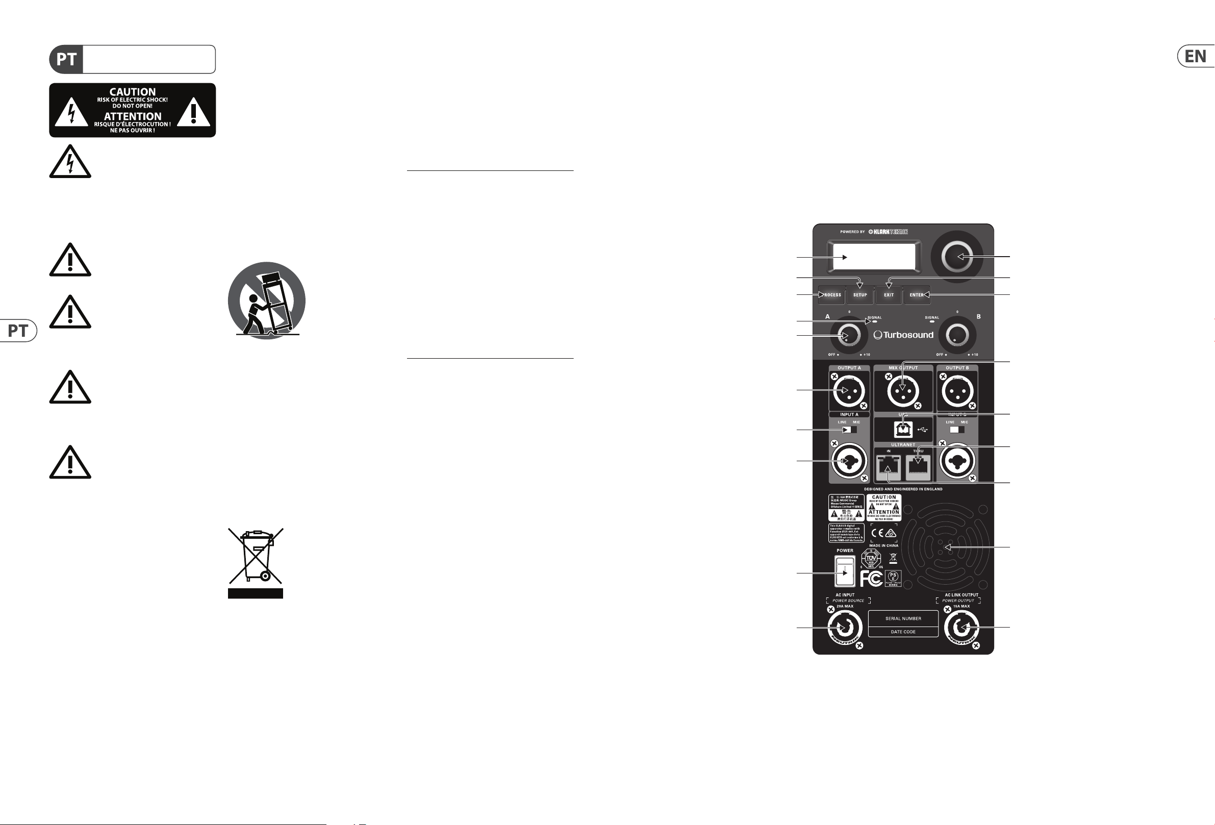
(1) LCD SCREEN displays the current DSP module and parameter settings.
(2) SETUP button steps through parameters within DSP processing modules.
(3) PROCESS button steps through the DSP processing modules.
(4) SIGNAL LED lights up to indicate the channel is receiving a signal.
(5) GAIN controls adjusts the analogue input level. To increase signal gain, rotate the controls clockwise; to reduce the gain, rotate the knobs counter-clockwise.
(Fullrange models have separate GAIN knobsfor channels A and B, while iQ15B and iQ18B subwoofers have a single dedicated A/B knob forbothchannels.)
(6) OUTPUT A/OUTPUT B XLR connectors provide un-processed copies of the INPUT A or INPUTBsignals.
(7) LINE/MIC switch adjusts the input sensitivity for INPUT A and INPUT B.
(8) INPUT A/INPUT B combo jacks accept input signals using XLR, balanced ¼" TRS or unbalanced ¼"TSconnectors.
(9) POWER switch turns the unit on and o .
(10) AC INPUT accepts power connections from power cables tted with Neutrik powerCON twist-lockingconnectors.
(11) ENCODER KNOB toggles between Graphic and Edit modes (when pressed) and changes parameter values (when rotated).
(12) EXIT button returns to the top-level DSP screen when pressed.
(13) ENTER button saves changes and deactivates Edit mode when pressed.
(14) MIX OUTPUT XLR jack (unavailable on iQ15B and iQ18B subwoofers) sends out a post-GAIN signal composed of the summed INPUT A and INPUT B signals.
(15) USB connection enables rmware updates and remote control over parameters via computer. Pleasevisit turbosound.com to download DSP control sof tware for
your computer.
(16) ULTRANET THRU sends out unprocessed digital audio from the ULTRANET IN connector to additional ULTRANET-equipped devices.
(17) ULTRANET IN RJ45 plug comes with 2 linked green status LEDs. Whenever a CAT5 cable has been connected, and a valid ULTRANET signal is detected, both LEDs
will light up simultaneously to indicate that the ULTRANET signal is ready to use.
(18) VENTILATION FAN speed adjusts automatically to ensure trouble-free operation.
(19) AC LINK OUTPUT connects power to other devices using power cables with Neutrik powerCON twist-locking connectors.
Networking capability
All iQ powered loudspeakers o er remote control via USB. The USB connection allows the user to con gure and monitor all DSP parameters using dedicated iQ
software for PC.
The DSP rmware can also be updated via the USB connection. Visitturbosound.com for the latest rmware version.
iQ speakers also o er proprietary ULTRANET networking capabilities through the ULTRANET IN and THRU connections using CAT5 cables with RJ45 connectors.
ULTRANET allows the user to transmit unidirectionally up to 16 independent channels of 24-bit audio throughout the iQ system, as well as other ULTRANET-equipped
devices such as digital mixers and personal monitor systems. Up to 7 devices can be connected in series on a single ULTRANET cable. ULTRANET can also be used for
remote control of the iQselection of modeled speakers.
ULTRANET connection with MIDAS M32 digital mixer and MIDAS DL16 digital snake
iQ18B iQ12 iQ18BiQ12
MIDAS M32
MIDAS DL16
Page 6

10 iQ Series Quick Start Guide 11
Networked mains power
iQ loudspeakers also facilitate networked transmission of mains power using power cables with NeutrikpowerCON locking power connectors. To set up networked
mains power between iQ loudspeakers, rstrun a power cable terminating in a powerCON connector to the AC INPUT connector on the rear panel. Topower additional
speakers downline, run power cables equipped with powerCON connectors at both ends from the rst speaker’s AC LINK OUTPUT to the AC INPUT of the next iQ
loudspeaker in series. Themaximum number of linked systems depends on the AC supply voltage as well as the maximum current draw of the individual systems in
the power chain. When linking a power chain, make sure that the integrated connectors as well as the supplied AC mains cable are never overloaded. If you are
uncertain how to calculate the total current draw, please contact your dealer.
iQ speakers powered in series
iQ DSP Menu Structure
Fullrange Subwoofer Function
PROCESS MODEL
Model "xyz" Model "xyz"
Choose from di erent sound Models, either the
TURBOSOUND signature voicing or a DSP model
of an industr y standard product.
(alt., MODEL active)
EQ
None None
Sets the frequency response to the default
setting.
Live Live
Sets the frequency response to a typical live
sound setting.
Speech Speech
Sets the frequency re sponse for optimal speech
intelligibility.
Playback Playback
Sets the frequency response ideal for music
playback.
User User
Lets you de ne your own frequency response
setting by entering the corresponding sub menu.
Sub menu
Low/ High Shelving Low/ High Shelving Lets you de ne a low and high shelving lter.
Parametric 1 & 2 Parametric 1 & 2
Lets you de ne a parametric bell-type EQ
(Frequenc y, Qual and Gain).
XOVER
None None
Unit is set for default full range/ subwoofer
reproduction.
—iQ8
Preset with ideal settings for use in combination
with iQ8 fullr ange speaker.
—iQ10
Preset with ideal settings for use in combination
with iQ10 fullrange speaker.
—iQ12
Preset with ideal settings for use in combination
with iQ12 fullrange speaker.
—iQ15
Preset with ideal settings for use in combination
with iQ15 fullrange speaker.
iQ15B —
Preset with high pass alignment for iQ15B
subwoofer.
iQ18B —
Preset with high pass alignment for iQ18B
subwoofer.
User User
User crossover sub menu for combination with
other fullrange or subwoofer speaker s ystems.
Sub Menu
Freq Freq
Select the desired crossover frequency:
For Fullrange Systems: 75 Hz to 400 Hz
For Subwoofer Systems: 50 Hz to 150 Hz
Phase Phase Adjust the absolute phase (0° or 180°)
Page 7

12 iQ Series Quick Start Guide 13
Fullrange Subwoofer Function
FBQ
Auto Auto
Automatically s ets as many lters as required.
Whenever a new feedback frequency is
discovered, the rst lter will be released to
attenuate the new frequenc y, and so for th.
Single Single
Activates the FBQ (feedback detection)
functionality, up to 8 feedback lters.
Learn Learn
Automatic procedure which searches for
feedback f requencies and lock s settings after all
8 lters have been set.
WARNIN G!
Please use ear protection during this
procedure. The feedback signal may
approach the system’s maximum level,
which may cause hearing damage!
Reset Reset Rese ts all lters.
SETUP
(page 1)
INPUT
Input Input
Lets you choose the audio input s ource. Chose
between Loc al (Analogue Input) or ULTRANET
(e.g., P16 monitoring system or
M32 audio via ULTRANET).
Tri m Tr im
Adjusts the input gain of the ULTRANET digital
inputs in a range
fm +10 dB to - 30 dB
Remote Remote
Enables ULTRANET remote control functionality
in order to protec t against misuse.
VU VU
Displays the respective input level of all 16
channels receiving via ULTRANET; only visible
when ULTRANET input is selected.
POSITION
Stand Floor
For positioning the speaker on a pole mount
stand (fullrange) or on the oor (subwoofer).
Wall Wall
For positioning the speaker on or next to a wall
( xed install); alternatively as a monitor speaker
(wedg e).
Ceiling —
For positioning the speaker on a wall ne xt to the
ceiling ( xed install).
Corner Corner
For positioning the speaker in a corner next to
the ceiling ( xed install); For positioning the
speaker in a corner (subwoofer).
DELAY
Delay Delay
Adjusts the amount of delay (max 300 msec =
103.08m or 338.19 feet).
Unit Unit Select s between msec, meter and feet.
LIMITER
Limit Limit
Adjust the limiter threshold for the input
signal (from OFF up to -30 dB). This threshold
adjustment allows you to set a max output power
which is below the iQ system’s rated ma x output.
Fullrange Subwoofer Function
SETUP
(page 2)
Vers ion Vers ion Displays the inst alled rmware version.
LOAD
1. - 20. 1. - 20.
To load a speci c preset, turn the encoder to
select the desired peset’s number, and then
either the ENTER button or the encoder. When
asked to con rm press the enco der again or EXIT
to abort.
SAVE
1. - 20. 1. - 20.
To save a preset choose the respec tive preset slot
and press ENTER or the encoder.
Sub Menu
Save Preset Save Preset
Name the preset by choosing the characters
with the encoder and pressing to con rm each
character. When nished, press the ENTER but ton
to save the prese t.
Setup
Contrast Contrast
Adjust LCD panel contrast.
The default contrast value is 15.
Screen Screen
ON: LCD screen saver (default)
turns on automatic ally after
approx. 2 minutes.
OFF : LCD turns o automatically after approx. 5
minutes.
Logo Logo
OFF: Deactivates front panel
logo illumination.
ON: Activates front panel
logo illumination.
LIMIT: Logo will light up when the limiter is
active.
SETUP
Sub Menu
Lock Lock
Lock the device and c reat a password by choosing
the password character s with the encoder
and pressing to con rm each character. When
nished press the ENTER but ton. Unlock the
device by entering the password or connecting
the unit via USB to a PC running iQ sof tware. The
soft ware does not require a password.
Warning Warning
In case of overheating, an alert appears on the
LCD screen, and the ampli er w ill shut down
until the unit cools.
LCD Graphic Indicators
To help the user immediately recognize that a parameter has been selected and changed from the initial default setting, the parameter’s related text on the top-level
screen will invert and change to black text on a white background. As an example, the following screenshots show how the text for the MODEL function changes when
the iQ8 default sound has been changed to the modeled PS8 sound:
This indicator function occurs only on the main DSP menu level and works for all DSP-related functions, except for the LOAD, SAVE and SETUP sub-sections on the
second page of the top-level SETUP menu.
Page 8

14 iQ Series Quick Start Guide 15
Mounting and xing
iQ series powered loudspeakers are designed with multiple internal rigging points to suit many possible mounting methods in permanent installations. All cabinets
can be simply suspended using optional M10 eyebolts coupled to the internal rigging points provided on the top, bottom, sides and back. The simplest method is to
use the two rigging points on the top and a single pull-back rigging point in the centre of the rear panel. Remove the appropriate plastic caps and insert eyebolts,
which must have a thread length of at least 30 mm. Use the rear rigging point to angle the cabinet for optimum room coverage.
Wall and Ceiling Brackets
TURBOSOUND iQ8-WB, iQ10-WB, iQ12-WB and iQ15-WB wall and ceiling brackets are optionally available for iQ series.
The graphic below shows the assembly of the optional mounting brackets (iQ8-WB, iQ10-WB, iQ12-WB and iQ15-WB).
Pole Mounting
Fullrange iQ loudspeaker models (iQ8, iQ10, iQ12 and iQ15) may also be pole mounted, eitherindependently or in conjunction with iQ subwoofer models (iQ15B, iQ18B).
The iQ pole mount sockets allow fullrange models to be mounted straight or angled 7.5° downwards for optimum coverage.
iQ10, iQ12 and iQ15 models may also be placed on one side and deployed as wedge monitors. Thesemodels have been designed with sides angled at 48° to help with
upward sound dispersion.
Transpo rt
The subwoofers are supplied with castors for ease of transportation when used as a portable sound system. To assemble the castors to the back of the cabinets, remove the 16
bolts from the rear of the speaker, align the castors w ith the mount holes and replace the bolts.
IMPORTANT NOTE: The mounting of a permanently installed sound system may be dangerous unless undertaken by quali ed personnel with the required experience and
certi cation to perform the necessar y tasks. Walls, oors or ceilings must be capable of safely and securely supporting the ac tual load. Themounting accessory used must be
safely and securely xed both to the loudspeaker and to the wall, oor or ceiling.
When mounting rigging components on walls, oors or ceilings, ensure that all xings and fasteners used are of an appropriate size and load rating. Wall and ceiling
claddings, and the construction and composition of walls and ceilings, all need to be taken into account when determining whether a particular xing arrangement can be
safely employed for a par ticular load. Cavity plugs or other specialist xings, if required, must be of an appropriate type, and must be tted and used in accordance with the
maker’sinstructions.
The operation of your speaker cabinet as part of a own system, if installed incorrectly and improperly, canpotentially expose persons to serious health risks and
even death. In addition, please ensure that electrical, mechanical and acoustic considerations are discussed with quali ed and certi ed (by local state or national
authorities) personnel prior to any installation or ying.
Make sure that speaker cabinets are set up and own by quali ed and certi ed personnel only, using dedicated equipment and original parts and components
delivered with the unit. If any parts or components are missing please contact your Dealer before attempting to set up the system.
Be sure to observe the local, state and other safety regulations applicable in your country. MUSIC Group, including the MUSIC Group companies listed on the enclosed
“Service Information Sheet”, assumes no liability for any damage or personal injury resulting from improper use, installation or operation of the product. Regular
checks must be conduc ted by quali ed personnel to ensure that the system remains in a secure and stable condition. Make sure that, where the speaker is own, the
area underneath the speaker is free of human tra c. Do not y the speaker in areas that can be entered or used by members of the public.
Speakers create a magnetic eld, even if not in operation. Therefore, please keep all materials that can be a ected by such elds (discs, computers, monitors, etc) at a
safe distance. A safe distance is usually between 1 and 2 metres.
ITEM DESCRIPTION QUANTIT Y
1 Yoke spacer 2
2
M5 x 25 mm screw with nylon
thread locking
4
Step 1: Secure Yoke Spacers
ITEM DESCRIPTION QUANTIT Y
1 Steel yoke bracket 1 1
2 Steel yoke bracket 2 1
3 Steel yoke bracket 3 1
4 M6 plain washer 6
5 M6 x 16 mm screw 6
6 M6 nylon locking nut 6
ITEM DESCRIPTION QUANTIT Y
1 Steel yoke bracket 1 1
2 Steel yoke bracket 2 1
3 M5 x 15 mm screw 2(IQ8) 4(iQ10)
4 M5 plain washer 2(IQ8) 4(iQ10)
5 M5 nylon locking nut 2(IQ8) 4(iQ10)
Step 2: Assemble Steel Yoke Bracket: IQ12 and iQ15
Step 2: Assemble Steel Yoke Bracket: iQ8 and iQ10
ITEM DESCRIPTION QUANTIT Y
1 Steel yoke bracket assembly 1
2 M8 x 25 mm screw 2
3 M8 plain washer 2
4 M8 spring lock washer 2
Step 3: Place Speaker Into Yoke Bracket
NOTE: For iQ8 and iQ10, the nished bracket requires only 2 pieces, while the iQ12 and iQ15 bracket requires 3 pieces.
YOKE VERTICAL MOUNTINGYOKE HORIZONTAL MOUNTING
1
3
2
1
3
2
Page 9

16 iQ Series Quick Start Guide 17
Technical Speci cations
iQ8 iQ10 iQ12
System
Frequency response
60 Hz – 18 kHz ±3 dB
55 Hz – 20 kHz -10 dB
55 Hz – 18 kHz ±3 dB
50 Hz – 20 kHz -10 dB
52 Hz – 18 kHz ±3 dB
45 Hz – 20 kHz -10 dB
Nominal dispersion 90° H x 90° V @ - 6 dB points 90° H x 60° V @ -6 dB points 80° H x 60° V @ -6 dB points
Maximum SPL 128 dB peak 129 dB peak 130 dB peak
Crossover type Ac tive Active Active
Transducers
1 x 8" (208 mm) LF driver
1 x 1" (25.4 mm)
HF compression driver
1 x 10" (256 mm) LF driver
1 x 1" (25.4 mm)
HF compression driver
1 x 12" (308.5 mm) LF driver
1 x 1" (25.4 mm)
HF compression driver
Limiter
Independent HF, LF,
peak and rms
Independent HF, LF,
peak and rms
Independent HF, LF,
peak and rms
Ampli er
Maximum output power* 2,500 W 2,500 W 2,500 W
Type Class-D Class-D Class-D
Protection Short circ uit, open circuit, thermal Shor t circuit, open circuit, thermal Short circuit, open circuit, thermal
Connectors
Input A / B 2 x combo jack/XLR 2 x combo jack/ XLR 2 x combo jack/XLR
Sensitivity Line +4 dBu, mic -22 dBu, swi tchable Line +4 dBu, mic -22 dBu, swi tchable Line +4 dBu, mic -22 dBu, swi tchable
Input impedance 20 k unbalanced, 40 k balanced 20 k unbalanced, 40 k balanced 20 k unbalanced, 40 k balanced
Maximum input level +21 dBu +21 dBu +21 dBu
Output A / B 2 x XLR Linked to input 2 x XLR Linked to input 2 x XLR Linked to input
Mix output XLR, balanced XLR, balanced XLR, balanced
Output impedance 100 unbalanced, 200 balanced 100 unbalanced, 200 balanced 100 unbalanced, 200 balanced
Ultranet input/link 2 x RJ45 2 x RJ45 2 x R J45
Mains Supply Neutrik powerCON input 20A and link 15A Neutrik powerCON input 20A and link 15A Neutrik powerCON input 20A and link 15A
Controls
DSP
Rotary push-encoder
Buttons for PROCESS, SETUP, EXIT, ENTER
Rotary push-encoder
Buttons for PROCESS, SETUP, EXIT, ENTER
Rotary push-encoder
Buttons for PROCESS, SETUP, EXIT, ENTER
Mixer section
2 x gain controls
(channels A and B)
2 x Line/Mic switch
2 x gain controls
(channels A and B)
2 x Line/Mic switch
2 x gain controls
(channels A and B)
2 x Line/Mic switch
User DSP Fun ctions
Factory EQ presets
Positioning, Sound mode,
Sound Modeling, FBQ
Positioning, Sound mode,
Sound Modeling, FBQ
Positioning, Sound mode,
Sound Modeling, FBQ
Display LCD 128 x 32, blue backlit LCD 128 x 32, blue backlit LCD 128 x 32, blue backlit
Delay 0 - 300 ms 0 - 300 ms 0 - 300 ms
Equalisation
High and low shelving EQ
2 x parametric EQ
High and low shelving EQ
2 x parametric EQ
High and low shelving EQ
2 x parametric EQ
Limiter Zero attack input limiter Zero attack input limiter Zero att ack input limiter
Presets 20 total presets, 19 user-de nable 20 total presets, 19 user-de nable 20 total presets, 19 user-de nable
Crossover High Pass L-R 24 dB/oct High Pass L-R 24 dB/oct High Pass L-R 24 dB/oct
Protection Lock-out func tion for all settings Lock-out function for all settings Lock-out function for all settings
iQ8 iQ10 iQ12
Ultranet Digital Network
System
Signal
Latency
16 ch annels
< 0.9 ms
16 ch annels
< 0.9 ms
16 ch annels
< 0.9 ms
Cabling
Cables
Cable length
Shielded CAT5
max. 246 ft / 75 m recommended
Shielded CAT5
max. 246 ft / 75 m recommended
Shielded CAT5
max. 246 ft / 75 m recommended
Power Suppl y
Power consumption 150 W @ ⁄ max power 150 W @ ⁄ max power 150 W @ ⁄ max power
Voltage (fuses)
USA / Canada 120 V~, 60 Hz (T 15 A H 250 V) 120 V~, 60 Hz (T 15 A H 250 V) 120 V~, 60 Hz (T 15 A H 250 V)
UK / Australia / Europe
220-240 V~, 50/60 Hz
(T 10 A H 250 V)
220-240 V~, 50/60 Hz
(T 10 A H 250 V)
220-240 V~, 50/60 Hz
(T 10 A H 250 V)
Korea / China
220-240 V~, 50/60 Hz
(T 10 A H 250 V)
220-240 V~, 50/60 Hz
(T 10 A H 250 V)
220-240 V~, 50/60 Hz
(T 10 A H 250 V)
Japan 100 V~, 50/60 Hz (T 15 A H 250 V) 100 V~, 50/60 Hz (T 15 A H 250 V) 100 V~, 50/60 Hz (T 15 A H 250 V)
Enclosure
Dimensions HWD
457 x 279 x 279 mm
(18.0x 11.0 x 11.0")
526 x 324 x 316 mm
(20.7x 12.7 x 12.4")
609 x 370 x 370 mm
(24.0x 14.5 x 14.5")
Net weight 14.7 kg (32 lbs) 17.2 kg (38 lbs) 21.1 kg (46 lbs)
Construction
Injection-moulded
polypropyleneenclosure
Injection-moulded
polypropyleneenclosure
Injection-moulded
polypropyleneenclosure
Finish Black painted Black painted Black painted
Grille Powder coated perforated steel Powder coated perforated steel Powder coated perforated steel
Flying hardware M10 x 3 points M10 x 3 points M10 x 3 points
Accessories
IQ8-WB Steel wall bracket IQ10-WB Steel wall bracket IQ12-WB Steel wall bracket
Page 10

18 iQ Series Quick Start Guide 19
iQ15 iQ15B iQ18B
System
Frequency response
50 Hz – 18 kHz ±3 dB
42 Hz – 20 kHz -10 dB
50 Hz – 130 Hz ±3 dB
40 Hz – 130 Hz -10 dB
50 Hz – 100 Hz ±3 dB
36 Hz – 100 Hz -10 dB
Nominal dispersion 75° H x 55° V @ -6 dB points Half Space Half Space
Maximum SPL 132 dB peak 130 dB peak 132 dB peak
Crossover type Ac tive Active Active
Transducers
1 x 1" (387 mm) LF driver
1 x 1" (25.4 mm)
HF compression driver
1 x 15" (385.7 mm) LF driver 1 x 18" (460 mm) LF driver
Limiter
Independent HF, LF,
peak and rms
Peak and rms Peak and rms
Ampli er
Maximum output power* 2,500 W 3,000 W 3,000 W
Type Class-D Class-D Class-D
Protection Short circ uit, open circuit, thermal Shor t circuit, open circuit, thermal Short circuit, open circuit, thermal
Connectors
Input A / B 2 x combo jack/XLR 2 x combo jack/ XLR 2 x combo jack /XLR
Sensitivity Line +4 dBu, mic -22 dBu, swi tchable Line +4 dBu Line +4 dBu
Input impedance 20 k unbalanced, 40 k balanced 20 k unbalanced, 40 k balanced 20 k unbalanced, 40 k balanced
Maximum input level +21 dBu +21 dBu +21 dBu
Output A / B 2 x XLR Linked to input 2 x XLR Linked to input 2 x XLR Linked to input
Mix output XLR, balanced N/A N/A
Output impedance 100 unbalanced, 200 balanced N/A N/A
Ultranet input/link 2 x RJ45 2 x RJ45 2 x R J45
Mains Supply Neutrik powerCON input 20A andlink 15A Neutrik powerCON input 20A andlink 15A Neutrik powerCON input 20A andlink 15A
Controls
DSP
Rotary push-encoder
Buttons for PROCESS, SETUP, EXIT, ENTER
Rotary push-encoder
Buttons for PROCESS, SETUP, EXIT, ENTER
Rotary push-encoder
Buttons for PROCESS, SETUP, EXIT, ENTER
Mixer section
2 x gain controls
(channels A and B)
2 x Line/Mic switch
1 x gain controls
(channels A and B)
2 x Line
1 x gain controls
(channels A and B)
2 x Line
User DSP Fun ctions
Factory EQ presets
Positioning, Sound mode,
Sound Modeling, FBQ
Positioning, Sound mode,
Sound Modeling, FBQ
Positioning, Sound mode,
Sound Modeling, FBQ
Display LCD 128 x 32, blue backlit LCD 128 x 32, blue backlit LCD 128 x 32, blue backlit
Delay 0 - 300 ms 0 - 300 ms 0 - 300 ms
Equalisation
High and low shelving EQ
2 x parametric EQ
High and low shelving EQ
2 x parametric EQ
High and low shelving EQ
2 x parametric EQ
Limiter Zero attack input limiter Zero attack input limiter Zero att ack input limiter
Presets 20 total presets, 19 user-de nable 20 total presets, 19 user-de nable 20 total presets, 19 user-de nable
Crossover High Pass L-R 24 dB/oct Low Pass L-R 24 dB/oct Low Pass L-R 24 dB/oct
Protection Lock-out func tion for all settings Lock-out function for all settings Lock-out function for all settings
iQ15 iQ15B iQ18B
Ultranet Digital Network
System
Signal
Latency
16 ch annels
< 0.9 ms
16 ch annels
< 0.9 ms
16 ch annels
< 0.9 ms
Cabling
Cables
Cable length
Shielded CAT5
max. 246 ft / 75 m recommended
Shielded CAT5
max. 246 ft / 75 m recommended
Shielded CAT5
max. 246 ft / 75 m recommended
Power Suppl y
Power consumption 150 W @ ⁄ max power 200 W @ ⁄ max power 200 W @ ⁄ max power
Voltage (fuses)
USA / Canada 120 V~, 60 Hz (T 15 A H 250 V) 120 V~, 60 Hz (T 15 A H 250 V) 120 V~, 60 Hz (T 15 A H 250 V)
UK / Australia / Europe
220-240 V~, 50/60 Hz
(T 10 A H 250 V)
220-240 V~, 50/60 Hz
(T 10 A H 250 V)
220-240 V~, 50/60 Hz
(T 10 A H 250 V)
Korea / China
220-240 V~, 50/60 Hz
(T 10 A H 250 V)
220-240 V~, 50/60 Hz
(T 10 A H 250 V)
220-240 V~, 50/60 Hz
(T 10 A H 250 V)
Japan 100 V~, 50/60 Hz (T 15 A H 250 V) 100 V~, 50/60 Hz (T 15 A H 250 V) 100 V~, 50/60 Hz (T 15 A H 250 V)
Enclosure
Dimensions HWD
711 x 450 x 381 mm
(27.9x 17.7 x 15.0")
602 x 445 x 495 mm
(23.7x 17.5 x 19.5")
691 x 533 x 559 mm
(27.2x 21.0 x 22.0")
Net weight 26.1 kg (57 lbs) 30.6 kg (67 lbs) 39.8 kg (87.5 lbs)
Construction Injection-moulded polypropyleneenclosure Birch plywood, screwed, andglued Birch plywo od, screwed, andglued
Finish Black painted Black painted Black painted
Grille Powder coated perforated steel Powder coated perforated steel Powder coated perforated steel
Flying hardware M10 x 3 points N/A N/A
Accessories
IQ15-WB Steel wall bracket
*indepen dent of limiters an d driver protec tion circuits
Technical Speci cations
Page 11

20 iQ Series Quick Start Guide 21
FEDERAL COMMUNICATIONS
COMMISSION COMPLIANCE
INFORMATION
Responsible Part y Name: MUSIC Tribe Brands UK Ltd.
Address: Klark Industrial Park,
Walter Nash Road,
Kidderminster, Worcestershire,
DY11 7HJ United Kingdom
Phone Number: +44 1562 732290
iQ18B/iQ15B/iQ15/iQ12/iQ10/iQ8
This equipment has been tested and found to comply withthe limits for a Class
B digital device, pursuant to part 15of the FCC Rules. These limits are designed
to provide reasonable protection against harmful interference in a residential
installation. This equipment generates, uses and can radiate radio frequency
energy and, if not installed and used in accordance with the instructions, may cause
harmful interference to radio communications. However, there is no guarantee that
interference will not occur in a particular installation. If this equipment does cause
harmful interference to radio or television reception, which can be determined
by turning the equipment o and on, the user is encouraged to try to correct the
interference by one or more of the followingmeasures:
• • Reorient or relocate the receiving antenna.
• • Increase the separation between the equipment and receiver.
• • Connect the equipment into an outlet on a circuit di erent from that to which the
receiver is connected.
• • Consult the dealer or an experienced radio/TV technicianforhelp.
This equipment complies with Part 15 of the FCC Rules. Operation is subject to the
following two conditions:
(1) This device may not cause harmful inter ference, and
(2) This device must accept any interference received, includinginterference that
may cause undesired operation.
Important information:
Changes or modi cations to the equipment not expressly approved by MUSIC Tribe
can void the user’s authority to use the equipment.
iQ18B/iQ15B/iQ15/iQ12/iQ10/iQ8
Other important information
1. Register online. Please register your new
MUSIC Tribe equipment right after you purchase it by
visiting turbosound.com. Registering your purchase using
our simple online form helps us to process your repair
claims more quickly and e ciently. Also, read the terms
and conditions of our warranty, if applicable.
2. Malfunction. Should your MUSIC Tribe
Authorized Reseller not be located in your vicinity,
you may contact the MUSIC Tribe Authorized Ful ller for
your country listed under “Support” at turbosound.com.
Should your country not be listed, please check if your
problem can be dealt with by our “Online Support” which
may also be found under “Support” at turbosound.com.
Alternatively, please submit an online warranty claim at
turbosound.com BEFORE returning the product.
3. Power Connections. Before plugging the
unit into a power socket, please make sure you are using
the correct mains voltage for your particular model.
Faulty fuses must be replaced with fuses of the same type
and rating without exception.
Important information
Page 12

 Loading...