

e-Boost-40 Instructionse-Boost-40 Instructions
Page 1
PART NUMBER
FG-EBOOST-40FG-EBOOST-40
e-Boost 40psi version 1.47
INTELLIGENT BOOST

e-Boost-40 Instructionse-Boost-40 Instructions
Page 2
PART NUMBER
FG-EBOOST-40FG-EBOOST-40
TABLE OF CONTENTS
1. BEFORE YOU START - IMPORTANT TIPS...................................................................... 3
2. INSTALLATION.................................................................................................... 3
2a. Packing list....................................................................................................................................................................................... 3
2b. Mounting the e-Boost................................................................................................................................................................... 4
2c. Installing the e-Boost solenoid ................................................................................................................................................. 5
2d. Wiring................................................................................................................................................................................................ 6
3. BASIC OPERATION................................................................................................7
3a. Live Mode ......................................................................................................................................................................................... 7
3b. Boost Pressure ............................................................................................................................................................................... 7
3c. Boost Parameters .......................................................................................................................................................................... 7
3d. User Parameters ............................................................................................................................................................................ 7
3e. Turning the e-Boost off .............................................................................................................................................................. 7
4. SETTING UP YOUR e-Boost ...................................................................................... 8
4a. Over Boost Shutdown – VERY IMPORTANT! ....................................................................................................................... 8
4b. e-Boost Readout ............................................................................................................................................................................ 8
4c. Bar Graph ......................................................................................................................................................................................... 9
4d. Setting Boost Pressure ............................................................................................................................................................... 9
4e. Sensitivity .......................................................................................................................................................................................10
5. ADVANCED SET-UP...............................................................................................11
5a. Setting Gate Pressure................................................................................................................................................................. 11
5b. Auxiliary Output ........................................................................................................................................................................... 11
5c. Audible Alarm ................................................................................................................................................................................12
5d. Using External Set Points ..........................................................................................................................................................12
5e. Peak Hold Function .......................................................................................................................................................................12
6. TROUBLESHOOTING .............................................................................................13

e-Boost-40 Instructionse-Boost-40 Instructions
Page 3
PART NUMBER
FG-EBOOST-40FG-EBOOST-40
1. BEFORE YOU START - IMPORTANT TIPS
- This Model e-Boost is capable of controlling boost pressures up to 2.72bar (40psi or 272kpa), for boost applications up to 4.08bar (60psi
or 408kpa) use FG-EBOOST-60.
- Turbosmart recommends that your e-Boost is fitted by an appropriately qualified technician.
- Consult your local tuning specialist before setting your boost pressure
- Setting boost beyond your engines capability can result in severe engine damage or failure!
- Turbosmart recommends that the engines Air/Fuel ratio is checked once the desired boost pressure is set, any increase in boost pressure
can cause the engine to run LEAN
- To safeguard against pinging or detonation, always use the highest octane fuel available
- A Turbosmart Fuel Cut Defender may need to be used in conjunction with your e-Boost, Please check out the www.turbosmart.com.au or
your nearest Authorised Turbosmart Dealer for more information on Fuel Cut Defenders
- Turbosmart recommends that boost pressure is set using a Dynamometer and not on public roads
2. INSTALLATION
2a. Packing list
The following components have been supplied with your e-Boost.
Quantity Description Use
1 e-Boost
1 e-Boost solenoid Use in conjunction with e-Boost
2 M3 Screws Secure e-Boost solenoid
2 M3 Nylock nuts Secure e-Boost solenoid
1 Wiring loom Connect e-Boost to vehicle
1 Earth eyelet Connect to chassis
100 mm Heat shrink Shield solder joints
2000 mm Figure eight wire Connect wiring loom to e-Boost solenoid
1 5 Amp fuse Connect to 12 Volts – see wiring
10 Cable ties Secure wiring
1 Panel mounting bracket Secure e-Boost to panel
2 M4 nuts Secure panel mount bracket
2 M4 spring washers Use with M4 nuts
1000 mm 2.5mm ID Polyurethane hose Connect to back of e-Boost
1000 mm 3mm ID Silicon hose Join polyurethane hose to intake manifold
1 Connecting barb Connect silicon hose to Polyurethane hose
1 Tee Piece Join 3mm Silicon hose to intake manifold
2 Small hose clamps Use on 3mm ID Silicon hose
500 mm 5mm ID Silicon hose Connect solenoid
4 Large hose clamps Use on 5mm ID Silicon hose
e-Boost-40 Instructionse-Boost-40 Instructions
Page 4
PART NUMBER
FG-EBOOST-40FG-EBOOST-40
2b. Mounting the e-Boost
- The e-Boost is designed to be panel mounted with the bracket supplied. Alternatively the e-Boost can be mounted in a 66mm (2 5/8 inch)
gauge cup.
- The e-boost is not waterproof and must be mounted accordingly, i.e. inside the cabin.
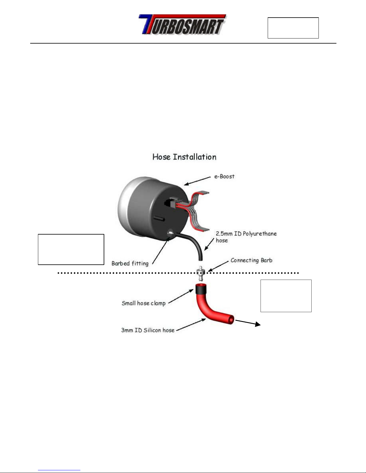
- Connect the 2.5mm hose to the barbed fitting on the back of the e-Boost. Ensure that it is pressed all the way on and take care not to kink
the hose when routing it through the dashboard.
- Connect the 3mm silicon hose to the 2.5mm hose with the connecting barb, ensure that the polyurethane hose does not enter the engine
bay. Route the 3mm silicon through the engine bay and connect the end to the inlet manifold.
- Use the small hose clamps supplied to secure the silicon hose.
Use the 3mm
silicon hose in
the engine bay
Use the 2.5mm
polyurethane hose
under the dashboard
Connect to inlet manifold

e-Boost-40 Instructionse-Boost-40 Instructions
Page 5
PART NUMBER
FG-EBOOST-40FG-EBOOST-40
2c. Installing the e-Boost solenoid
- Mount the e-Boost solenoid in an appropriate position in the engine bay with the screws supplied.
- The e-Boost solenoid is rated to 100 degrees Celsius (212 degrees Fahrenheit), ensure that it is mounted a minimum of 250mm away from
the turbo or exhaust manifold, otherwise heat-shielding maybe required.
- If your vehicle is fitted with a factory boost control solenoid it MUST BE REMOVED from the hose that runs between the pressure
source and the wastegate actuator, failure to remove the solenoid will cause erratic or fluctuating boost pressure.
- Ensure that the factory boost control solenoid remains connected to the ECU’s wiring harness.
- Connect the ports on the e-Boost solenoid according to the appropriate diagram below, use the 5mm ID silicon hose supplied, secure all
connections with hose clamps supplied.
 Loading...