


Document Type: |
Instruction Manual |
Product Name: |
E-Boost Street 40PSI |
Product Description: |
Electronic boost controller |
Product Number: |
TS-0302-1002 |
------------------------------------------------------------------------------------------------------------------------
BEFORE YOU START – IMPORTANT NOTES
Turbosmart recommends that your E-Boost Street is fitted by an appropriately qualified technician.
Consult your local tuning specialist before setting your boost pressure as setting boost beyond your engines capability can result in severe engine damage or failure
Turbosmart recommends that the engines Air/Fuel ratio is checked once the desired boost pressure is set. Any increase in boost pressure can cause the engine to run lean resulting in severe engine damage or failure
Turbosmart recommends that the E-Boost Street is not used in conjunction with any type of “Draw Through” induction System.
Turbosmart recommends that boost pressure is set using a Dynamometer and not on public roads.
The E-Boost Street may not be able to completely compensate for a drop in boost pressure at high RPM due to the turbocharger operating beyond its maximum efficiency range i.e. incorrect turbocharger sizing or excessive exhaust backpressure.
The E-Boost Street cannot compensate for increases in boost pressure at high RPM due to inadequate waste gate flow capacity; the turbo system must maintain a steady base boost curve before you start using a boost controller.
The E-Boost Street cannot be used with external waste gates that are in a poor, worn or non-serviceable condition.
For best results your turbocharger should be correctly sized for your application.
Erratic operation of electronic parts can be caused by Electro Magnetic Interference (EMI). EMI can be generated by aftermarket ignition systems such as CDI which, if wired incorrectly, generate large amounts of EMI through the vehicles electrical system. This can cause items such as ECU’s and boost controllers to be effected. Please follow ignition system installation instructions VERY carefully to avoid EMI affecting the E-Boost Street. Sometimes, using resistor type spark plugs can reduce this problem.
The E-Boost Street is not waterproof and must be mounted inside the cabin. The unit has an operating temperature range of -5OC to 70OC.
1
CONTENTS |
|
INSTALLATION .................................................................................................................. |
3 |
Wiring .............................................................................................................................................. |
3 |
RPM Signal Connection (OPTIONAL) ........................................................................................... |
3 |
Vacuum/pressure signal ................................................................................................................... |
4 |
Installing the E-Boost Street Solenoid ............................................................................................. |
4 |
SOLENOID HOOK UP METHODS ..................................................................................... |
4 |
INTERNAL WASTEGATE CONNECTION ................................................................................. |
5 |
Single solenoid, single turbocharger hook up .................................................................................. |
5 |
Single solenoid, twin parallel turbocharger hook up ....................................................................... |
6 |
Twin solenoid, twin parallel turbocharger hook up ......................................................................... |
6 |
EXTERNAL WASTEGATE CONNECTION ................................................................................ |
7 |
Single port, single solenoid, single turbo connection Method ......................................................... |
7 |
Single port, single solenoid, twin turbo connection Method ........................................................... |
7 |
Single port, twin solenoid, twin turbo connection Method.............................................................. |
8 |
Two port, single solenoid, single turbo connection Method (1) ...................................................... |
8 |
Two port, single solenoid, twin turbo connection Method (1)......................................................... |
9 |
Two port, twin solenoid, twin turbo connection Method (1) ........................................................... |
9 |
Two port, single solenoid, single turbo connection Method (2) .................................................... |
10 |
Two port, single solenoid, Twin turbo connection Method (2) ..................................................... |
10 |
Two port, twin solenoid, Twin turbo connection Method (2)........................................................ |
11 |
Two port, single 4 port solenoid, single turbo connection Method (3).......................................... |
11 |
Two port, single 4 port solenoid, twin turbo connection Method (3) ............................................ |
11 |
Two port, twin 4 port solenoid, twin turbo connection Method (3)............................................... |
12 |
BASIC FUNCTIONALITY.................................................................................................. |
13 |
Unit Layout .................................................................................................................................... |
13 |
OFF mode ...................................................................................................................................... |
13 |
Live mode menu............................................................................................................................. |
13 |
Changing between 2 boost groups ................................................................................................. |
13 |
SETUP............................................................................................................................... |
14 |
OVER BOOST SHUTDOWN (OBS) ........................................................................................... |
15 |
SCALE (SCL) ................................................................................................................................ |
15 |
BOOST SETUP (bG1 and bG2) .................................................................................................... |
15 |
Setting SP1 (Set point):.......................................................................................................... |
16 |
Setting GP1 (Gate pressure):................................................................................................ |
16 |
Setting SN1 (Sensitivity): ....................................................................................................... |
16 |
RPM DISPLAY CONFIGURATION (CYL)................................................................................ |
17 |
LIGHT DIM (DM)......................................................................................................................... |
17 |
SWITCH LOGIC (sL) ................................................................................................................... |
17 |
AUXILIARY OUTPUT (AU) ....................................................................................................... |
17 |
BOOST CORRECTION (COR) .................................................................................................... |
17 |
SECURITY PIN (PIN)................................................................................................................... |
18 |
RPM SHIFT LIGHT (RL) ............................................................................................................. |
18 |
ZERO DISPLAY (ZER) ................................................................................................................ |
18 |
SOLENOID CYCLE(SOL) ........................................................................................................... |
19 |
FACTORY RESET (RES)............................................................................................................. |
19 |
TROUBLESHOOTING ...................................................................................................... |
19 |
2

INSTALLATION
Wiring
(Solder all wires together and insulate the joints with the supplied heat shrink)
Note: Unused wires must be insulated with electrical tape so that they do not touch other wires or the chassis
Red Wire – +12 Volts switched through ignition – connect via 5 Amp fuse supplied
Black Wire – Chassis, earth or ground
Yellow Wire – To 3.5V – 12V Square wave (RPM) Signal OPTIONAL
Green Wire – External set point switching (Ground to activate) OPTIONAL
Orange Wire – Dimming trigger (Ground to activate) OPTIONAL
White Wire – Auxiliary Output (Negative switched) OPTIONAL
Brown and grey wire – to boost control solenoid (Polarity not important)
RPM Signal Connection (OPTIONAL)
RPM signal connection is ONLY for Tacho mode, RPM set point mapping, Boost correction, shift light function and other advanced features. Turbosmart recommends your RPM signal be connected by an appropriately qualified technician or automotive electrician. For further information consult your vehicle’s manuals or your local automotive electrician. The E-Boost Street is ONLY able to accept an RPM signal in the form of a square wave that is switching between 0V and 3.5-12 volts.
The following points should be followed to connect your RPM signal to an ECU pin.
-Locate your ECU RPM signal wire and splice into the signal wire coming from your ECU.
-Check the output you are splicing into is a square wave that is switching between switching between 0V and 3.5-12 volts with an appropriate meter.
-Connect the yellow RPM wire from the E-Boost Street to the spliced section of the ECU RPM out.
-Turn on the E-Boost Street and configure your signal to the number of cylinders or rotors your engine has using the CYL (cylinder) parameter located in the setup menu.
-In live mode with your engine running press mode once to show live RPM. The display should be reading RPMx100 e.g. 015 on the display indicates 1500 RPM. If the display is not reading correctly re-check the cylinder configuration in the setup menu.
-Note: If the OEM tachometer does not display RPM after installing the E-Boost Street, a 2 ohm or higher resistor needs to be installed in line between the ECU RPM output pin and the E-Boost Street.
The following points should be followed to connect your RPM signal to the negative terminal of an ignition coil. NOTE: Caution should be exercised when connecting to the negative terminal of an ignition coil and Turbosmart recommends an ECU connection where possible. IMPORTANT! The RPM signal should not be connected to a coil of a capacitive discharge ignition (CDI) system.
3
-Check the signal from the negative terminal is a square wave that is switching between switching between 0V and 3.5-12 volts with an appropriate meter. If the voltage is below 3.5V (coil trigger signals tend to have a very low voltage) the e-Boost will not read a signal. In this case, a signal amplifier (also known as a tach adapter) must be used to boost the signal.
-Connect the RPM signal wire from the E-Boost Street to the negative terminal of an ignition coil or tach adapter (which ever method is used).
-Turn on the E-Boost Street and configure your signal to the number of cylinders or rotors your engine has using the CYL (cylinder) parameter located in the setup menu
-In live mode with your engine running press mode once to show live RPM. The display should be reading RPMx100 e.g. 015 on the display indicates 1500 RPM. If the display is not reading correctly re-check the cylinder configuration in the setup menu.
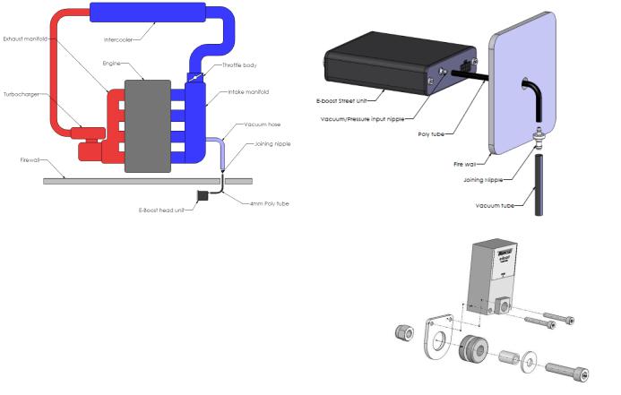
Vacuum/pressure signal
The E-Boost Street requires a vacuum/pressure signal from the intake manifold to function. A combination of poly tube and silicone hose is used to connect the E-boost Street to a adequate vacuum/pressure signal. Route the poly tube from the E-boost Street head unit through the fire wall approximately 100mm (4”) only as the poly tube is not rated to the high temperatures of the engine bay.
Use the connecting barb to join the poly tube to the 3mm ID silicon hose at the firewall/bulkhead. Ensure the poly tube is pressed all the way onto the connecting barb
Route the silicon hose through the engine bay and connect it to a pressure/vacuum signal from the inlet manifold. Use the supplied tee piece if necessary.
Secure all connections with the supplied hose clamps
Installing the E-Boost Street Solenoid
-The E-Boost Street solenoid is rated to a maximum temperature of 100 degrees Celsius (212 degrees Fahrenheit), ensure that it is mounted a minimum of 250mm (10 Inches) away from the heat of the turbo or exhaust manifold, otherwise heat shielding maybe required.
-Mount the E-Boost Street solenoid in an appropriate position in the engine bay with the mounting kit supplied.
-Fit the rubber grommet inside the mounting plate. Slide the sleeve inside the grommet. Use the M3 screws to bolt the solenoid to the mounting bracket – Note use loctite on the threads to secure. Use the M6 screw, washer and Nyloc nut to mount in a suitable location in the engine bay.
-The E-Boost Street head unit is capable of controlling two solenoids. The use of twin solenoids is not necessary but is recommended in twin turbo setups on V configuration engines as this reduces the length of hose required for plumbing which aids in response and control of the wastegates.
-The solenoid must be connected to a pressure only source which must be located before the intercooler, ideally off the compressor cover of the turbocharger. The air temperature before the intercooler is less affected by ambient conditions which will give you more consistent boost control.
SOLENOID HOOK UP METHODS
WARNING! Changing to different connection method can cause a higher than expected increase in boost pressure. Turbosmart recommends adjusting your boost controller back to its minimum setting and measuring the new minimum boost pressure achieved by the new setup before increasing your boost again.
4
Note: If your vehicle is fitted with a factory boost control solenoid, the hoses that run from the pressure source and to the wastegate actuator must be disconnected. Leave the solenoid plugged into the wiring loom so that the ECU is not affected. Failure to disable the factory boost control solenoid and hoses will result in erratic or fluctuating boost pressures which could damage your engine.
INTERNAL WASTEGATE CONNECTION
WARNING! Changing to different connection methods can cause a higher than expected increase in boost pressure. Turbosmart recommends adjusting your boost controller back to its minimum setting and measuring the new minimum boost pressure achieved by the new setup before increasing your boost again.
Note: If your vehicle is fitted with a factory boost control solenoid, the hoses that run from the solenoid to the pressure source and to the wastegate actuator must be disconnected from the solenoid. Leave the solenoid plugged into the wiring loom so that the ECU is not affected.
Most factory turbocharged vehicles use an internal waste gate system to control boost pressure. The E-Boost Street controls boost pressure by controlling the pressure signal that the waste gate actuator receives from the turbocharger. Please note that the E-Boost Street cannot be used to obtain a boost pressure lower than the standard waste gate actuator’s pressure setting.
Some factory hoses have a small restrictor fitted inside them, if the factory hoses are reused over boosting or boost spiking may occur.
Secure all connections with hose clamps.
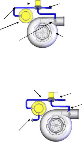
Single solenoid, single turbocharger hook up (Basic single internal wastegate setups)
Port (1): vents pressure from the solenoid. Connect this hose to the intake side of the turbo, between the air cleaner and the inlet of the turbocharger. Otherwise connect a short piece of the silicon hose and face the vent downwards to stop water or debris
entering the solenoid.
Solenoid
Port (2): to the internal wastegate actuator
|
Port (3): to pressure only source |
Port 2 of solenoid |
|
|
|
|
|
to actuator |
|
|
Actuator |
|
|
Pressure only source to |
|
|
Port 3 of solenoid |
Port 1 of solenoid vent to atmosphere
Turbocharger
If you are unable to achieve your desired boost pressure, it is normally due to exhaust manifold backpressure forcing the internal waste gate to open. To increase your boost pressure further, fit a higher pressure waste gate actuator to increase your minimum boost pressure.
WARNING! Fitting a higher pressure waste gate actuator may cause a higher than expected increase in boost pressure.
Turbosmart recommends resetting the boost set point values to Zero and measure the new minimum boost pressure before increasing your boost set point values.
Internal wastegates with 2 ports |
Port 2 of solenoid |
|
|
to actuator |
|
Port (1): vents pressure from the solenoid. |
Port 1 of solenoid vent |
|
|
to atmosphere |
|
Port (2): connect to one of the ports of the actuator |
Pressure only |
|
|
||
Port (3): to pressure only source |
source to port 3 |
|
of solenoid |
||
|
Block off unused port on the actuator with suitable blank
Block off unused port
5

Single solenoid, twin parallel turbocharger hook up
(For straight configuration twin parallel turbocharger engines E.g. RB26DETT)
The E-Boost Street is capable of controlling twin internal wastegate turbochargers with a single solenoid.
This method is used when the turbochargers are mounted close to each other allowing the solenoid to be mounted close to both actuators
Each solenoid port is connected as follows:
-Port (1): vents pressure from the solenoid. Connect this hose to the intake side of the turbo, between the air cleaner and the inlet of the turbocharger. Otherwise connect a short piece of the silicon hose and face the vent downwards to stop water or debris entering the solenoid.
-Port (2): to tee piece that feeds both actuators
-Port (3): to pressure only source
Port 2 of solenoid to tee piece
Tee Piece
Actuator
Block off with suitable blank
Port 1 of solenoid Vent to atmosphere
Port 3 of solenoid to pressure only source
Actuator
Turbochargers
Twin solenoid, twin parallel turbocharger hook up
(For V configuration twin parallel turbocharger engines E.g. V6, V8 etc)
The E-Boost Street is capable of controlling two solenoids for twin parallel turbocharger setups.
This method is used when there is a great distance between the wastegates. This allows the solenoids to be mounted close to the wastegates to minimise the length of hose used and to maximise response
You will need a second solenoid for this method (TS-0301-3003)
Connect the grey wire from the e-Boost wiring loom to one of the wire from each solenoid.
Connect the brown wire from the e-Boost wiring loom to the remaining wire from each solenoid.
Each solenoid port is connected as follows:
-Port (1): vents pressure from the solenoid. Connect this hose to the intake side of the turbo, between the air cleaner and the inlet of the turbocharger. Otherwise connect a short piece of the silicon hose and face the vent downwards to stop water or debris entering the solenoid.
|
Wires to E-Boost |
-Port (2): to the internal wastegate actuator |
|
|
Port 1 of solenoid |
Port (3): to pressure only source |
vent to atmosphere |
Port 2 of solenoid to actuator
Pressure only source to port 3 of solenoid
6
 Loading...