

Turbosmart BLOW OFF VALVES User Manual
1
------------------------------------------------------------------------------------------------------------------------
Quantity
Description
Use
1
BOV Controller Unit
BOV Controller
1
Race Port assembly
Blow off valve fitted with orange inner spring and stainless steel weld flange
2m
2 core wire
Connect BOV Controller to solenoid
1
Heat shrink
Insulating soldered joints
2
Double sided adhesive
Surface mounting BOV controller
2
M3 X 30 Screws
Mounting BOV controller
2
M3 Nuts
Mounting BOV controller
1
3 Port solenoid
Controls pressure to BOV
3
1/8 NPT nipples
Connects solenoid to hose
1.2m
6.3mm Reinforced pressure tube
To connect the solenoid to the BOV
1
Solenoid Bracket
Mounting the solenoid
2
M3X20 SHCS
Mounting bracket to solenoid
2
5 amp Fuses
To protect the BOV controller and solenoid from voltage problems
1
M6 Nut
Secure solenoid bracket to car
1
M6 X 25 SHCS
Secure solenoid bracket to car
1
M6 Washer
Secure solenoid bracket to car
10
Cable ties
Securing vacuum tube and wires
1
Crimp ring terminal
For ground connection
4
Hose clamps
Securing all pressure lines
1
8 way wiring loom
Connects BOV Controller to devices and power
Product Name: BOV Controller Kit
Product Description: Electronic BOV controller
Product Number: TS-0304-100X
1
2
3
4
5
6
7
8
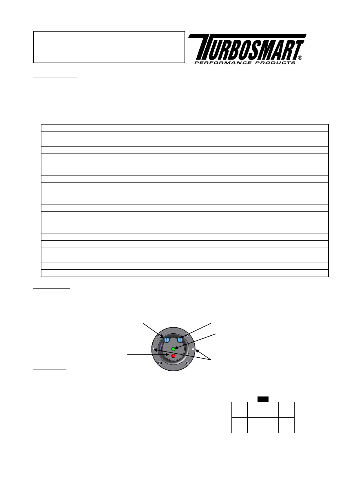
Looking into BOV
Controller
Duration adjustment
Sensitivity adjustment
Power LED
Activation LED
Mounting Holes
IMPORTANT NOTES:
Please thoroughly read and understand these instructions before commencing this installation.
RECOMMENDATIONS
• Turbosmart recommends that your BOV controller is fitted and adjusted by an appropriately qualified technician
Turbosmart recommends that a boost gauge be permanently fitted to the vehicle
------------------------------------------------------------------------------------------------------------------------
Please check that the following items have been provided in your BOV Controller Kit
FUNCTIONALITY
The BOV controller works by detecting a negative voltage change in throttle position. It then energises the solenoid to vent all of the air
out of the BOV cap, causing a pressure differential between the piston of the BOV and the cap which will vent pressure from the intake
system. There are 2 parameters that can be adjusted to tune the controller for optimum performance; duration and sensitivity. The green
LED shows that the BOV controller is on. The yellow LED shows when the solenoid is activated.
LAYOUT
INSTALLATION
Mount the unit away from any heat source and moisture. Wire up the unit as per diagram. Do not connect the unit to a power supply
which will have a greater voltage than 14V DC. Unused wires must be insulated with electrical tape so that they do not touch
other wires or the chassis
1. ORANGE = +5V (For external TPS) – OPTIONAL if your engine does not have a OEM TPS
2. GREEN = 0V (For external TPS) - OPTIONAL if your engine does not have a OEM TPS
3. WHITE = TPS signal Input
4. YELLOW = Solenoid trigger signal
5. GREY = Disable Trigger wire (Ground to disable Controller) - OPTIONAL
6. BROWN = Enable Trigger wire (Ground to keep solenoid energised) - OPTIONAL
7. BLACK = Controller Ground
8. RED = +12V (USE SUPPLIED 5A Fuse inline)
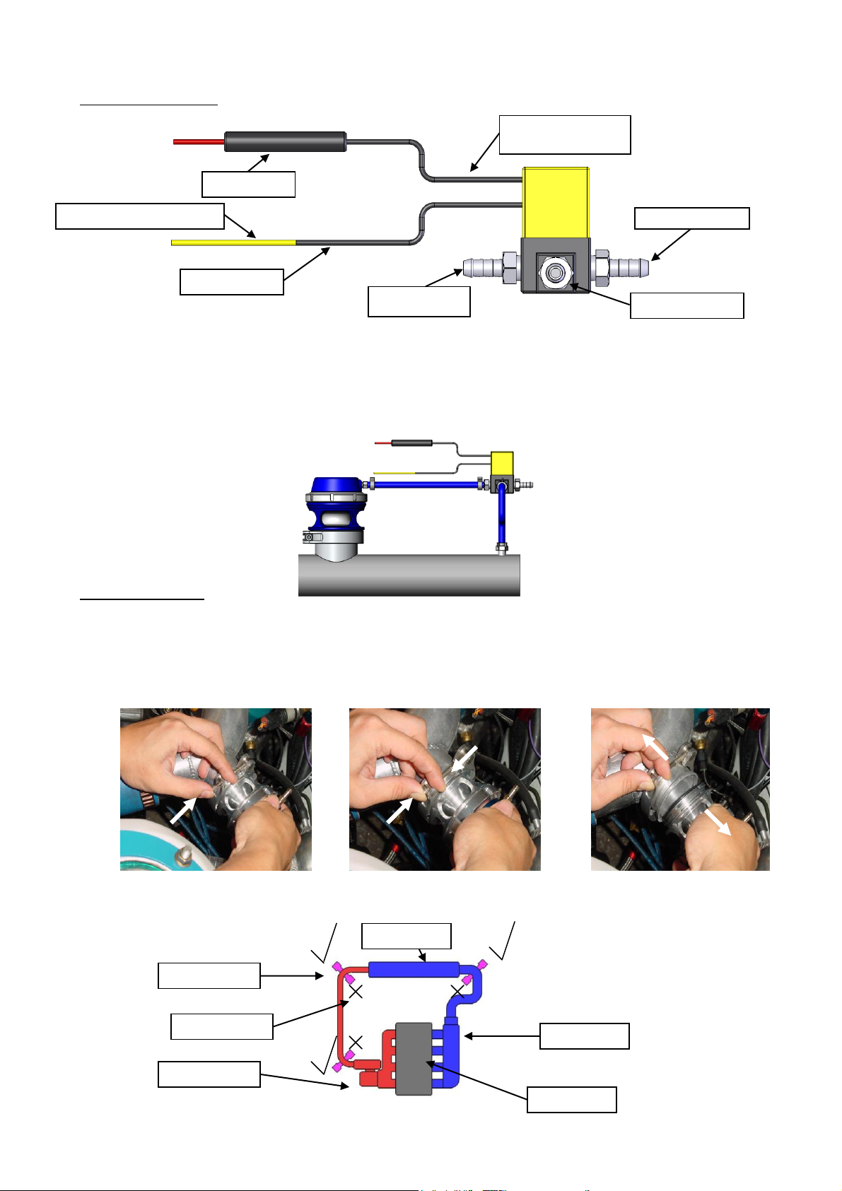
2
Wire from solenoid
(1) Vent to atmosphere
Supplied 5A fuse
Wire from solenoid:
Connect to Ignition activated
(3) To pressure source
(2) To pressure
nipple on BOV
Bolt head
Squeeze
Lift off
Pull down
Inlet manifold
Turbocharger
Intercooler
Engine
Good position
Bad Position
Yellow wire from control unit
SOLENOID CONNECTION
Electrical connection
Connect one wire of the solenoid to a fused (use supplied fuse) ignition activated 12V power source and connect the other wire to the
Solenoid trigger signal (Yellow) on the BOV controller unit. Polarity is not important.
Pressure connection
Port 1: Vent to atmosphere.
Port 2: To pressure nipple of BOV.
Port 3: To pressure source e.g. Intercooler piping (Make sure the pressure source is not shared and that it is from the same part of the
pipe work as the BOV)
MOUNTING YOUR BOV
Allow the engine to cool down before installing your Race Port
Identify a suitable location along the intercooler/intake piping for the Race Port – this will need to be between the outlet of the turbo
and the intake manifold ideally between the intake manifold and the intercooler
Remove the Race port from the stainless steel weld on adapter by removing the V-Band clamp. The V-band clamp is removed by
opening the screw until it has reached the end stop, then pushing the head of the screw in a “syringe” like motion and lifting the
Race Port off the stainless steel weld flange.
Step 1: Step 2: Step 3:
Weld the stainless steel adapter onto the intercooler pipe in your ideal position, then allow the adapter to cool down
 Loading...