

Page 1

TurboChef Service Manual
()
Accelerating the World of Cooking
800.90TURBO
art Number: NGC-1007 / Revision A, July 23, 2004
P
Page 2

IMPORTANT SAFETY INFORMATION - PLEASE READ FIRST
: Improper installation, adjustment, alteration, service or maintenance can cause property
damage, injury or death. Read the installation, operating and maintenance instructions thoroughly
before installing or servicing this equipment.
This element is
This pr
HOT during operation and will remain at dangerous temperatures after the unit is switched off. NEVER
oduct emplo
ys an exposed radiant heating element on the bottom of the cavity
.
attempt to touch the element during operation or while the oven is warm.
x
o
stor
e or use gasoline or any other flammable vapors or liquids in the vicinity of this or any
other appliance.
The information contained in this manual is impor
tant for the pr
oper installation, use and maintenance
of this oven. Adherence to these procedures and instructions will result in satisfactory baking results and
vice. Please read this manual carefully and retain it for future reference.
long tr
ouble-fr
ee ser
Errors - descriptive, typographic or pictorial - are subject to correction. Specifications are subject to change
without notice.
Page 3

Table of Contents
Important Safety Instructions i
Precautions to Avoid Possible Exposure to Excessive Microwave Energy ii
Grounding Instructions ii
RF Interference Considerations ii
Chapter 1: Installation, Specifications and Maintenance
Specs and Dimensions 1
imensions
D
Construction
Standard Features
Accessories
Certification
Packaging
Power Supply - North America
Delivery and Product Placement 2
Lifting and Placement of the Oven
Restraint Oven Kit
Electrical Specifications 2
Setup and Initial Operation 2
Setup
Programming
Initial Power-Up
Maintenance 3
Chapter 2: Theory of Operation
Theory of Operation 5
The
Glossary of Common Operating Terms 6
Chapter 3: F
To View Fault Codes 9
Fault Code Definitions 9
ault Code
F
Chapter 4: The Contr
Control System Schematic 11
Control System Component Descriptions 12
Test Function Options 13
tatus I
S
Programming 14
User Configurable Options 15
asswor
P
Control System Panel Parts 17
Control System Trouble Shooting 18
ault Codes
able
T
ndicators
ds
10
ol System
14
16
Page 4

Chapter 5: The Microwave System
Overview of a Microwave Circuit 21
Monitor Circuit Description 21
Microwave Circuit Theory of Operation 22
Microwave System Parts 22
Microwave System Components 23
Wave Guide Cover Replacement 24
Wave Guide/Wave Guide Cover Parts 25
Wave Guide Replacement and Cleaning 26
High Voltage Transformer & Filament Transformer Replacement 26
iring the High Voltage Transformers
W
Wiring the Filament Transformers
Measuring RF Leakage for Microwave Safety 27
esting Microwave Components 28
T
Testing the High Voltage Diode
Checking a Diode
Checking a Capacitor
Checking a Magnetron for Open/Shared Filament
Checking a High Voltage Transformer or Filament Transformer
High Voltage and Filament Transformer Resistance Table 29
Microwave System Trouble Shooting 30
Chapter 6: The Cook Door
Removing/Reinstalling the Cook Door 33
Cook Door Parts 33
Adjusting the Cook Door 34
Adjusting the Primary and Secondary Interlock Switches 34
Primary and Secondary Interlock Switches Adjustments and Parts 35
ts
witch Assembly and P
oor S
D
Adjusting the Monitor Safety Switch 36
M
onitor Safety Switch Parts 37
Cook Door Assembly 38
Cook Door Parts 38
Screw Torque Chart 39
Interlocks Trouble Shooting 40
Chapter 7: The Convection Circuit
Convection System Components 41
Convection Circuit Parts 42
Blower Motor Parts 43
Convection Circuit Trouble Shooting 44
M
otor
inding R
W
esistance
ar
able 45
T
36
Page 5

Chapter 8: IR Element and Catalytic Converter
Components 47
IR Element and Catalyst Removal 47
Removing the IR Element
Removing & Installing the Catalytic Converter
Installing a New IR Element
IR Element and Catalytic Converter Parts 48
Chapter 9: Schematic and Schematic Parts
NGC (Tornado) Schematic Inside 49
Schematic P
Line Voltage Components
Low Voltage Components
W
I/O Control Board Item Identification and Test Point Locations 49
Chapter 10: Service Parts and Illustrations
Figure 4: NGC (Tornado) Control System 51
Figure 12: Control System Panel Enclosure and Parts 52
Figure 13: Monitor Circuit - Shown in Failsafe State 53
Figure 15: Microwave System Parts 53
Figure 16: Microwave System Parts 54
Figure 17: Wave Guide Cover/Wave Guide Removal and Replacement 54
Figure 18 & 19: High Voltage Transformer and Filament Wirings 55
Figure 21&22: High Voltage Diode and Magnetron 55
Figure 23: Cook Door Removal and Parts 56
Figure 26: Primary and Secondary Interlocks Adjustment and Parts 56
Figure 27: Door Switch Assembly and Parts 57
e 28: M
igur
F
Figure 29: Cook Door Assembly 59
F
igure 31: Convection Circuit Block Diagram 60
Figure 32: Convection Circuit Assembly and Parts 61
Figure 33: Blower Motor Parts and Assembly 62
Figure 34: IR Element and Catalytic Converter Parts and Assembly 63
Figure 35: NGC (Tornado) Schematic 64
e 36: I/O Contr
igur
F
Figure 37: Covers and Miscellaneous Parts 66
arts 49
ire Harness Replacement P/N’s
otor S
witch A
djustment and Assembly 58
ol Board and Test Point Locations 64
Page 6

INTRODUCTION
i
IMPORT
ANT SAFETY INSTRUCTIONS
The following basic safety precautions should be strictly adhered to when using electrical appliances, so as
to reduce the risk of burns, electric shock, fire, injury to persons or exposure to excessive microwave energy.
o
Read all instructions before using the appliance.
o
Read and follow the Specific Precautions to Avoid Possible Exposure to Excessive Microwave Energy
found on page ii.
o
This appliance must be grounded. Connect only to properly grounded outlet. See Grounding Instructions
found on page ii.
o
Install or locate this appliance only in accordance with the provided installation instructions.
o
Some products such as whole eggs and sealed containers - for example: closed glass jars - may explode
and should not be heated in this oven.
o
Use this appliance only for its intended use as described in this manual.
o
This appliance should be serviced only by qualified service personnel. Contact the nearest authorized
service facility for examination, repair or adjustment.
o
Keep cord away from heated surfaces.
x
o
allow children to use this appliance.
x
o
use corrosive chemicals or vapors in this appliance. This type of oven is specifically designed
to heat, cook or dry food. It is not designed for industrial or laboratory use.
x
o
operate this appliance if it has a damaged cord or plug, is not working properly, or has been
damaged or dropped. See Power Supply Cord Replacement found on page ii.
x
o
cover or block any openings on the appliance.
x
o
store this appliance outdoors.
x
o
use this product near water - for example: near a kitchen sink, in a wet basement or near a
swimming pool.
x
o
immerse cord or plug in water.
x
o
let cord hang over edge of table or counter.
x
o
use a water jet for cleaning. See the Maintenance section of this manual on page 3 for proper
cleaning procedures.
To reduce the risk of fire in the oven cavity:
o
Remove wire twist-ties from paper or plastic bag in the oven.
o
f materials inside the o
I
en should ignite, keep o
v
ven door closed, turn oven off and disconnect the power
cord or shut off power at the fuse or circuit breaker panel.
o
f smoke is observed, switch off or unplug the oven. Keep the door closed in order to stifle any flames.
I
x
o
use the cavity for storage purposes.
x
o
overcook food. Carefully attend the oven if paper, plastic or other combustible materials are
placed inside the oven to facilitate cooking.
x
o
leav
e paper pr
oducts, cooking utensils or food in the cavity when not in use.
TRUCTIONS
VE THE
A
S
SE INS
Page 7

ii
INTRODUCTION
CAUTIONS TO AVOID POSSIBLE EXPOSURE TO EXCESSIVE MICROWAVE ENERGY
PRE
To reduce the risk of exposure to excessive microwave energy:
x
o
attempt to operate this oven with the door open. Open-door operations can result in harmful
exposure to microwave energy. It is important not to defeat or tamper with the safety interlocks.
x
o
place any object between the oven front face and the door or allow soil or cleaner residue to
accumulate on the sealing surfaces.
x
o
operate the oven if it is damaged. It is particularly important that the oven door close properly
and that there is no damage to the door (bent), hinges and latches (broken or loosened), door seals and
sealing surfaces.
x
o
have the oven adjusted or repaired by anyone except a factory authorized service technician.
GROUNDING INSTRUCTIONS
This appliance must be grounded. In the event of an electrical short circuit, grounding reduces the risk of
electric shock by providing an escape wire for the electric current. This appliance is equipped with a cord
that has a grounding wire with a grounding plug. The plug must be plugged into an outlet that is properly
installed and grounded. Consult a qualified electrician or serviceman if uncertain about the ability to follow
grounding instructions or if doubt exists as to whether the appliance is properly grounded.
x
o
use an extension cord. If the power supply cord is too short, have a qualified electrician or
serviceman install an outlet near the appliance.
Power Supply Cord Replacement
If the power supply cord is damaged, it must be replaced by the manufacturer, its service agent or a similarly
qualified person in order to avoid a hazard.
: Improper grounding can result in a risk of electric shock.
RF INTERFACE CONSIDERATIONS
ornado) oven generates radio frequency signals. This device has been tested and was determined
The NGC (
T
to be in compliance with applicable portions of FCC part 18 requirements and to the protection requirements of Council Directive 89/336/EEC on the approximation of the laws of the Member States relating
to electromagnetic compatibility at the time of manufacture. However, some equipment with sensitivity
to signals below these limits may experience interference.
ence, the follo
our equipment experiences inter
f y
I
o
Increase the physical separation between this oven and the sensitive equipment.
o
f the sensitiv
I
o
f battery powered microphones are being affected, insure that the batteries are fully charged.
I
o
Keep sensitive equipment on separate electrical circuits if possible.
x
o
route intercom wires, microphone wires or speaker cables near the oven.
e device can be gr
fer
ounded, do so following accepted grounding practices.
wing steps should be considered:
VE THE
A
S
SE INS
TRUCTIONS
Page 8

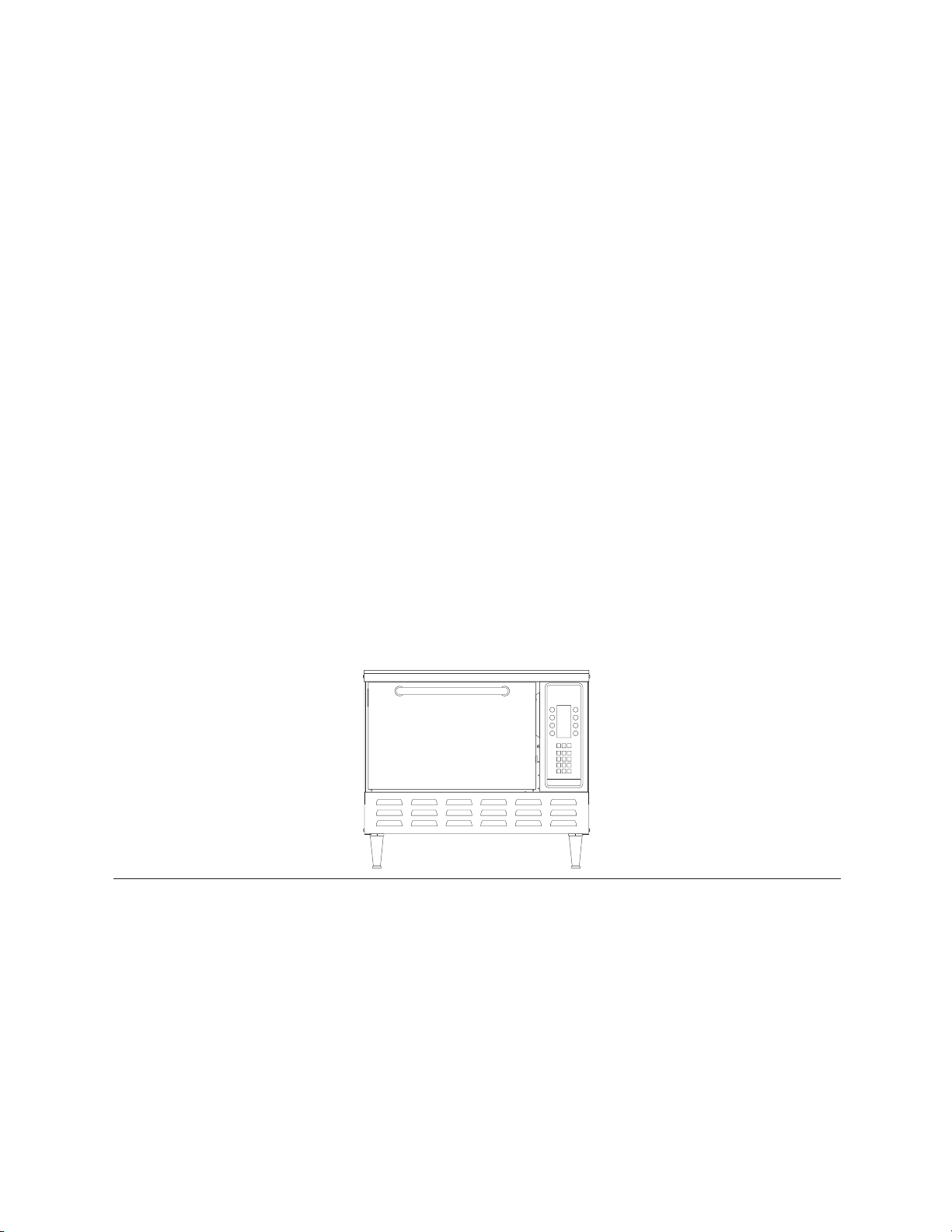
: NGC (Tornado) Dimensions
INSTALLATION, SPECIFICATIONS AND MAINTENANCE
1
SPECS AND DIMENSIONS
Dimensions
Height 23” (with 4” legs) 8”
Width 26” 15.5”
Depth 25.7” 14.7”
28.2” (with handle)
Weight 190 lbs.
ack 0”
B
Sides 2”
(minimum)
Crated 30”
ncrated
U
24”
Construction
o
430 stainless steel front, top and sides.
o
4” chrome plated adjustable legs
o
ickel plated handle
N
o
Cool to the touch pull down door
Standard Features
o
Recirculating airpath with TurboChef
Technologies patented catalytic converter system
o
Multi-speed convection blower
o
Conventional wire baking rack
o
Independently controlled bottom browning
element
o
Stackable design
o
Smart Voltage Sensor Technology
o
actory programmed with up to
F
ograms
pr
o
Smart Card for remote programming
o
Warranty - 1 year parts and labor
128 cooking
Accessories (Additional Charge)
o
24” stainless steel oven stand with locking casters
for single units
o
tainless steel o
17” s
en stand with
v
locking casters
for stacked units
Certifications
UL, cUL, NSF
, FDA, FCC
o
304 stainless steel line
o
Fully insulated cooking chamber
o
Removable wire cooking rack with optional platter
o
Adjustable lo
er cooking element
w
ackaging
P
ens are packaged in a double-wall corrugated
v
All o
box with integrated corrugated skids.
Page 9

2
INSTALLATION, SPECIFICATIONS AND MAINTENANCE
Power Supply - North America
Universal Voltage: 208/240 VAC, 60 Hz,
1 phase
Amperage: Nameplate rating 30 Amp
(3-wire including ground)
Cordset: 10 gauge, 3 conductor,
5 foot cordset
Plug: NEMA 6-30
:
mart Voltage Sensor Technology does
The S
not compensate for lack of or over voltage situations.
It is the responsibility of the owner to supply voltage
to the unit accor
DELIVERY AND PRODUCT PLACEMENT
ding to the above specifications.
Remove oven from carton. Immediately note any
damage and contact shipping company within 24
hours in order to file a claim. TurboChef will not
be responsible for product damaged in shipment.
The carton may be discarded after oven is removed.
: Oven weight is approx. 190 lbs.
Two or more persons are required to lift it.
Proper installation instructions are included in the
Restraint Oven Kit, if the operator has ordered one.
If additional help is needed, please call customer
service at
ELECTRICAL SPECIFICATIONS
800.90TURBO.
Operating Voltage 208 VAC/240VAC
Current Draw 30 Amps
Phase 1 Phase
Frequency 60 Hz
Max Input 5990/6675 watts
Microwave Input Power 3500 watts*
*Maximum Independent Input Power
: Never lift the oven by its door
handle. Physical damage to the oven and/or
personal injury may result. The operator must ensure
that the oven is properly placed on the countertop
at all times. TurboChef will not recognize a fallen
oven as a warrantable claim and is not liable for any
injuries that may result.
SETUP AND INITIAL OPERATION
Lifting and Placement of the Oven
Position one or more persons on either side of the
oven and lift from the bottom. Never lift the oven
lace the oven on a coun-
. P
om the fr
fr
ont and r
ear
tertop surface at least 28 inches deep and capable
of suppor
ting 200 lbs.
Once properly positioned on the counter, plug the
oven into a NEMA 6-30R wall mounted electrical
pecifications.
eceptacle. S
r
ee E
lectrical
S
Restraint Oven Kit (P/N TC3-0240)
en
An optional system intended to hinder the o
v
from moving forward during use and/or cleaning.
The Restraint Oven Kit will not prevent the oven
from falling off a countertop if the legs are allowed
to slide off the edge or if the oven is intentionally
or forcefully pulled off.
Setup
Once oven is properly positioned on the counter,
emove any packing material and/or any foreign
r
objects from within the cavity. Install the oven rack
es.
y sliding the rack onto the suppor
b
t shelv
Programming
en comes preprogrammed and is ready to
v
The o
operate out-of-the-box.
Initial Power-up
To turn the oven On, press the “On” Key next to
the word “On” on the display. The oven will begin
to warm up to its pr
edefined cooking temperatur
of 500ºF. This takes approximately 10 minutes.
When the
Warm-up Cycle is completed, the oven
will beep and display the “Ready State”. At this
point, the oven is ready to cook.
e
Page 10

INSTALLATION, SPECIFICATIONS AND MAINTENANCE
1 2 3 4 5
3
DAILY MAINTENANCE FOR THE NGC
The Daily Cleaning Recommendation below will
help in maintaining the NGC (Tornado) oven. Be
®
sure to use only TurboChef
Oven Cleaner. The use
of any other cleaning products can damage critical
parts and may void warranty on those parts.
Supplies and Equipment
TurboChef®Oven Cleaner, nylon green scrub pad,
cleaning towel
Step 1: Prepare the Oven.
o
Turn oven off by pressing the “Back” key.
o
The oven will display “Oven Off-Cooling Down”.
x
o
attempt to clean oven during the cool
cle, indicated by “Cooling Down” signal
wn cy
do
on display.
o
Cooling takes approximately 90 minutes.
:
The o
en operates at 500
v
º
F and may cause
injury if not allowed to cool properly.
e the Lower Access Panel.
v
Step 2: R
o
emo
Wipe out any crumbs that have collected.
876
9
10
Step 4: Lift Bottom Element.
o
Be sure the bottom element is cool prior to lifting.
: The oven element operates at 1000ºF and
may cause injury if not allowed to cool properly.
Step 5: Remove Particles and Spray Oven Interior
with TurboChef
o
Using a damp towel, remove any large particles
®
Oven Cleaner.
from the oven.
o
If stubborn stain is present, sparingly spray
®
TurboChef
Oven Cleaner into the cavity and
on the door.
o
Allow cleaner to penetrate for five (5) minutes.
o
Never saturate the bottom of the oven with
water or oven cleaner.
Step 6: Clean Ov
o
Using a nylon green scrub pad, clean the oven
door and cavity
en Interior
.
.
: Do not apply pressure to white
Wave Guide Caps. Breaking will result in a
non-warranty ser
vice call.
Step 3: Remove the Wire Rack.
o
Wash, rinse and sanitize the wire rack.
en interior is cool prior to
v
: Be sur
e o
removing the wire rack.
Step 7: Wipe Out Oven Interior.
o
W
en door and cavity clean using a
v
ipe o
damp towel.
o
Wipe the element with a clean damp towel.
Page 11

4
INSTALLATION, SPECIFICATIONS AND MAINTENANCE
Step 8: Clean Area where Lower Access Panel
is Located.
o
Wipe the area on the outside of the oven where
the lower access panel is located.
x
o
spray any chemical in this area.
T:
DO NO
x
o
Lift oven by handle.
x
o
Slam or mishandle the oven door.
x
o
Place foil or metal objects of any kind in the oven.
x
o
Operate the oven without food in the cook
chamber.
x
o
Step 9: Lower the Bottom Element and Replace the
Wire Rack and Lower Access Panel.
Step 10: Clean Oven Exterior.
o
ipe the oven exterior with a clean, damp towel.
W
o
Oven is ready to turn on.
Frequently open and close the door to check
the product.
x
o
Cook items wrapped in plastic or any type of
cling film.
x
o
Put products in the oven until ready to cook.
x
o
Use cleaning agents that are not approved for
the oven.
x
o
DO’S AND DO NOT’S
DO:
o
Ensure the oven is cleaned daily.
o
Use only TurboChef®Oven Cleaner.
o
Remove items from the oven as soon as they
Allow any cleaning solution or water to remain
on the bottom of the cooking chamber after
cleaning or at any other time.
x
o
Place excessive weight on top of the oven.
are cooked.
o
Use only microwave-safe TurboChef approved
cooking accessories in the oven.
o
Review cooking instructions to ensure oven settings are correct for corresponding products.
o
Keep the TurboChef Installation Guide for
future reference.
o
Call TurboChef immediately if Wave Guide
Caps are broken.
Page 12
THEORY OF OPERATION
5
THE THE
ORY OF OPERATION
The TurboChef NGC (Tornado) oven utilizes three
independent heat transfer mechanisms in order to
rapidly cook food.
The systems are as follows:
o
Convection
o
Infrared energy
o
Microwave energy
By combining these mechanisms along with the
ability to control each mechanism independently,
the NGC (Tornado) oven is able to reduce the cook
time of most foods by 70-90 percent.
Figure 2 below represents the oven’s different systems
and the critical components of each system. Should
a problem arise with any of the components listed
below, please turn to the appropriate section within
this manual for further instructions.
For the purpose of this manual, each independent
heat transfer mechanism is individually identified.
For instance, if an oven is experiencing difficulties
browning the food, focus on the Convection Circuit
and/or the Infrared Circuit, versus the Microwave
Circuit. Focus on the Microwave System if an oven
is browning the food but not heating the food.
Chapter 4
CONTROL SYSTEM
I/O Contr
ol Boar
Keypad
isplay
D
Mechanical Relays
SS Relays
: NGC (
Tornado) Systems and Critical Components
Chapter 5
WAVE SYSTEM
MICRO
d
M
H
ilament Transformers
F
ons
agnetr
Voltage Transformers
igh
High Voltage Capacitors
High Voltage Diodes
Fuse
Chapter 7
CONVECTION SYSTEM
ection Heater
Conv
Blower Controller
Convection Blower
Catalytic Converter
i-Limit
H
Thermostat
Chapter 8
BOTTOM IR AND CCV
Bottom I
nfrared Element
Mechanical Relays
SS Relays
Page 13

6
THEORY OF OPERATION
OSSARY OF COMMON OPERATING TERMS
GL
Off State
º
All the oven’s control systems are off and the Cook Chamber Temperature is below 150
F.
Cool Down
A subset of the Off State. During Cool Down the oven will circulate the main convection blower until
the Cook Chamber Temperature is below 150ºF.
Ready State
Refers to an oven that has successfully warmed-up to the predefined Set-Temperature. At this point the
oven control is ready to receive cook commands via the Keypad.
Set-Temperature (TSET)
A predefined temperature at which the oven cooks.
Cook Chamber Temperature (TCC)
The actual temperature registered by the Cook Chamber Thermocouple.
Edit Mode
The mode which enables the user to change stored or predefined Recipes and the Set-Temperature.
Warm-Up
The mode when the oven is warming itself to the Set-Temperature.
Idle Mode
Similar to the Ready State. In this mode, the oven’s control may cycle the blower or heaters in order to
maintain the Set-Temperature.
Cook Cy
cle
A period of operation as defined by a Recipe.
est Mode
T
A special diagnostic mode that enables the service technician to turn on and off all oven systems
independent of one another
.
Keypad
The primary interface for the operator.
Display
isplays all visual information to the operator
D
.
Self-Test (STEST)
A special diagnostic function that tests all critical subsystems to determine their operational state.
Recipe
A set of user defined Events that determine a Cook Cycle.
Page 14

THEORY OF OPERATION
Events
A single operational element that is a part of a Recipe. Each Recipe may have up to six Events depending
on programming. Each Event lasts a percentage of the Total Cook Time and can be set between 0 and
100% of the Total Cook Time. The sum of all the Event Percent (%) Times must equal 100%.
Total Cook Time
The total duration of a Recipe.
Percentage (%) Time
An event subset that specifies the duration of the Event.
Percentage (%) Air
An event subset that specifies the relative amount of impingement airflow (speed of convection motor)
during the E
vent. Valid between 10 and 100%.
: Maximum 100% = 7100 RPM Blower Motor Speed. Blower Motor Speed scale is linear.
7
Percentage (%) Microwave (MW)
An event subset specifying the microwave cycle (on time) during the Event. Valid between 0 and 100%.
Fault Code
A code assigned to an Event that the Control considers to be a failure. Upon discovering a Fault, the
Control will display the Fault Code and a brief description of the failure. The Control will also increment
the Fault Code Counter.
Error Message
A message that is displayed when an unusual event occurs. The Control will display the Error Message
only when it occurs. Error Messages are not logged in the Fault Code Counter.
Page 15

The NGC (Tornado) oven has the ability to continually
COOK COUNT
F1 BLOWER
F2 LOW TEMP
F3 MAG CURR
F4 MONITOR
F5 MAG TEMP
F6 TEMP
S/N XXXXXX
NGCVXXXX XXXXXX
0
0
0
0
0
0
0
monitor and log various fault conditions. Some fault
conditions will terminate Cook Cycles, while others
will not. Please refer to the Fault Code Table on
page 10 for more detailed information.
When a fault is detected, the Fault Code Counter
will increment. However, if the fault is subsequently
cleared by some action, whether service related or
not, the Fault Code Counter will not decrement.
FAULT CODES
9
TO VIEW FAULT CODES
To view the Fault Log, press the “4” and “6” Keys
simultaneously while the oven is in the Off State.
The oven will display all faults logged. Figure 3.
Each Fault Log will log up 255 instances before
rolling back to zero. Press the “0” Key to reset the
Fault Code Counter.
: The Fault Log also displays the Cook
Counter, which will log up to 65,535 Cook Cycles.
In order for the Control to log a Cook Cycle, the
oven must complete the first Event of any given
Recipe. If a Recipe only has one (1) Event, the oven
must complete the entire Cook Cycle in order to
count the Cook Cycle.
T CODE DEFINITIONS
UL
A
F
F1: Blower Running Status Bad
Fault is displayed when the Blower Controller
indicates no running status.
: Fault Display
F2: Cook Temperature Low
Fault is displayed if the Cook Chamber Temperature
is more than 84ºF below the Set Temperature after
five (5) seconds into a Cook Cycle.
The fault is cleared at the onset of cooking if the
Cook Chamber Temperature is within 84
º
F of the
Set Temperature or when the heater is tested in the
Test Mode.
F3: Magnetron Current Low
Fault is displayed when the Current Transformer
(CT) on the I/O Control Board does not detect
enough current. The Fault is monitored when the
microwave is on during a Cook Cycle or Self-Test.
The fault is cleared at the onset of a Cook Cycle if
the CT detects current or when the magnetron is
successfully energized in the Test Mode.
The Motor and Motor Controller state is monitored
continuously in all M
odes with special handling in
the Self-Test and Test Mode. If a fault is detected,
the Control will bounce the oven into the Off State.
Upon turning the oven On, the Control will attempt
to restart the M
fault indication will be cleared. The fault is also
cleared at the onset of cooking or when the blower
is tested in the
T
f the r
. I
otor
est Mode.
t is successful the
estar
F4: Door Monitor Defective
ault is displayed when the Control detects that the
F
Monitor Interlock Switch unlatches before both the
Primary and Secondary Interlock Switches during a
Cook Cycle.
In addition this fault will blow the F3 Fuse if the
microwave high voltage system is energized when
the fault occurs.
The fault is clear
ed only when the
oven is turned Off and On.
Page 16

10
FAULT CODES
: Door Interlock Switches are in parallel. See
Figure 35, on the inside of page 49. The fault is
monitored during a Cook Cycle or Self-Test, when
the Microwave is on.
F5: Magnetron Over Temperature
Fault is displayed when the Thermostat on either
Magnetron is “Open”.
The fault is cleared at the onset of a Cook Cycle if
the Thermostat is closed or when the Magnetron is
successfully tested in the Test Mode.
C (Electrical Compartment) Temperature High
F6: E
Fault is displayed when the EC Thermocouple
exceeds 158ºF and is monitored once per minute.
The fault is cleared when the EC Thermocouples
temperature is below the indicated limit.
FAULT CODE TABLE
F7: Thermocouple Open
Fault is displayed when the Control detects that
either the IR or CC Thermocouple is “Open”.
o
999ºF indicates the CC Thermocouple is “Open”.
o
1999ºF indicates the IR Thermocouple is “Open”.
Fault is cleared when the control detects continuity
on the open Thermocouple Circuit.
F8: Heat Lo
w
An Error Message (not a Fault Code) displayed
during Warm-up or Self-Test if the Cook Chamber
emperature (TCC) fails to rise 14ºF within thir
T
ty
(30) seconds.
FAULT CODE AND DESCRIPTION WHEN ACTIVE REFER TO
Self-Test
X
X
X
X
X
Page 19
Page 20
Page 30
Page 36
age 2
P
age 12
P
Page 18
Page 44
4
F1: Blower Running Status Bad
F2: Cook Temperature Low
F3: Magnetron Current Low
e
F4: D
oor M
onitor D
efectiv
F5: Magnetron Over Temperature
F6: EC Temperature High
F7: Thermocouple Open
eat Low
F8: H
ault Codes ar
F
e listed in or
der of hierar
Warm - up
X
X
X
X
. For example: If during cooking the oven experiences an F1
chy
Idle Mode
X
X
X
Cook Mode
X
X
X
X
X
X
X
and F2 Fault, the oven will only report a F1 Fault since the software will halt all actions upon discovering
the F1 Fault. F7 and F8 F
aults ar
e displayed on the primary screen and are not displayed or counted in
the Fault Log.
: All Fault Codes listed in Bold will terminate a Cook Cycle upon discovery. Any fault occurring
in a Cook Cycle will be logged in the Fault Code Counter.
Page 17

THE CONTROL SYSTEM
VOLT
(100783)
IR THERMOCUOPLE
EC THERMOCUOPLE
CC THERMOCUOPLE
A(-
)
C(+
)
A(-
)
C(+
)
A(-
)
C(+
)
VOLTAGE INPUT
COMMON
12 14
KEYPAD
(NGC-1110)
VDF
DISPLAY
(100505)
COMMON
SECONDARY SWITCH
INTERLOCK
PRIMARY SWITCH
INTERLOCK
PRIMARY SWITCH
(102012)
(102012)
SECONDARY SWITCH
12 25 26
12 25 26
12 25 26
12 25 26
12 14
12 14
12 14
IR ELEMENT COMMAND
CONVECTION HEATER COMMAND
+24 VDC
+24 VDC
MONITOR
INTERLOCK
MONITOR S
WITCH
(102012)
DUAL
SSR
RELA
Y
(10
1284)
K5 K4
3
(+)
3(+)4(-
)
4(-
)
+24 VDC
+24 VDC
COMMON
K6
MECH
RELAY
(101272)
K3
MECH
RELAY
(101271)
K2
MECH
RELAY
(101271)
K1
MECH
RELAY
(101271)
+24 VDC - + 24 VDC - + 24 VDC - + 24 VDC -
I/O
CONTROL
BOARD
(NGC-1008)
24 VDC
POWER SUPPLY
(101206)
L
N
+V
-V
1
2
3
1
2
3
4
1
2
3
4
5
6
200-240
VAC IN
240 VAC
3 PHASE
OUT
BMSC
(100443)
0-10V
I/O COM
I/O COM
ENABLE
STATUE OK
I/O COM
SPD
CMD
NC
C
NO
NC
C
NO
NC
C
NO
11
The Control System is comprised of the components
that signal, sense, command and switch the oven’s
various components. Figure 4 shows a functional
diagram of all the components that make up the
Control System.
: The part numbers for each component are
given within the parentheses in addition to being
included with the descriptions for each part on the
following page.
: NGC (Tornado) Control System
Page 18

12
THE CONTROL SYSTEM
CONTROL S
YSTEM COMPONENT DESCRIPTIONS
24 VDC Power Supply (P/N 101206)
24 VDC Output at 40 Watts. Supplies control
voltage for I/O Control Board, 24 VDC Mechanical
Relays and Solid State Relays.
K1 Mechanical Relay (P/N 101271)
240 VAC, 30 Amp, Double Pole, Double Throw, 24
VDC Relay Coil.
Switches power to the Magnetron
Filament Transformers.
K2 Mechanical Relay (P/N 101271)
240 VAC, 30 Amp, Double Pole, Double Throw, 24
VDC Relay Coil.
Switches power to the Magnetron
High Voltage Transformers.
K3 Mechanical Relay (P/N 101271)
240 VAC, 30 Amp, Double Pole, Double Throw, 24
VDC Relay Coil.
Safety Interlock device designed to
short L1 and L2 if the Monitor Switch opens before
the Primary and Secondary Interlock Switches.
EC Thermocouple (P/N 700-1179)
Type K Thermocouple. Thermocouple measures the
temperature of the Electrical Compartment. If the
temperature within the Electrical Compartment is
º
above 158
F, the Control displays “F6 - EC Temp”.
CC Thermocouple (P/N NGC-1140)
Type K Thermocouple. Thermocouple measures
the temperature of the re-circulating impingement
airflow. Valid IR Set points are 450-540ºF. If the
display indicates 999ºF
, the Thermocouple is Open.
BMSC (P/N 100443)
oprietary Brushless DC Motor Controller
A pr
designed solely to operate the Convection Motor.
VDF Display (P/N 100505)
Vacuum Fluorescent Display.
Keypad (P/N NGC-1110)
3x8 Matrix Membrane Switch. Keypad is connected
to the Control via a 14 Pin Flat Cable.
K4/K5 SSR (P/N 101284)
240 VAC, Dual 40 Amp Solid State Relay. K4
(right) controls the Convection Heater and K5
(left) controls the IR Element.
K6 Mechanical Relay (P/N 101272)
C, 30 A
A
V
240
VDC Relay Coil.
mp,
Responsible for switching between
ouble Throw, 24
ole, D
ee P
Thr
the 208VAC and 240VAC taps on the High
ilament
oltage and
V
F
Interlock Switches (P/N 102012 for all thr
Transformers.
ee)
Primary, Secondary and Monitor Interlock Switches.
Switches must be actuated by the Cook Door in the
following order: M-S/P. When the Cook Door
ersed: P/S-M.
opens, the or
der is r
ev
IR Thermocouple (IR Element)
Type K Thermocouple. Thermocouple is embedded
in the IR Element. The Thermocouple measures
the internal/sheath temperature of the IR Element.
Valid IR Set points are between 500ºF and 1200ºF.
The display indicates 1999ºF, if the Thermocouple
is “Open”.
Voltage Sense Module (P/N 100783)
Proprietary device designed to measure incoming
line voltage and switch between 208 and 240 VAC
operation. The device only measures and configures
the oven when the oven is switched from the Off
tate.
tate to the O
S
TE
S
T MODE
Test Mode allows the service technician to
The
n S
operate the oven’s subsystems individually. It also
allows the operator to configure various presets.
To enter the Test Mode:
1. Press the “Back” Key until the display is in the
tate.
ff S
O
2. Press the “Back” and “Enter” Key simultaneously.
Enter the access code: 9-4-2-8 when prompted
3.
and press “Enter”.
The “Test” Screen displays the Software Version,
Cook Chamber and IR E
lement
emperatur
T
e at the
top of the screen. The Control also displays the
Page 19

CC 810F
TEST NGC VXXXX
IR 500
0
F
BLOWER
HEATER
FAU
LTS MGTRON
STEST
IR ELE
PSM A
th Wi
CC 810F
TEST NGC VXXXX
IR 500
0
F
DIAG
0
ELEC
CCC F/C
PIN
IR SI
P
SM A
t
hWi
: Test Mode - Screen 1 : Test Mode - Screen 2
THE CONTROL SYSTEM
13
first of two (2) pages of the test function options
(Figure 5). To display the second page (Figure 6),
press either the “Down or Up Arrow” Key. To test a
component or sub-system, press the corresponding
Soft Key.
TEST FUNCTION OPTIONS
Blower Speed
The “Blower” Key increments the Blower Speed in
10% steps. When the Blower Speed is 100%, the
next press sets the speed to 0%.
onic Compartment Temperature
Electr
The “ºELEC” Key displays the temperature inside
the electronic enclosure.
Self-Test Function
The “STEST” Key initiates the Self-Test function
to test all major components of the o
v
Self-Test, press the corresponding Soft Key once.
ress the “Back” Key to return to the Idle Mode.
P
Heater Test
The “Heater” Key turns the heater On or Off. If
the heaters ar
Key turns the heaters Off. If the heaters are Off
pressing the “H
e O
eater
ey turns the heaters On. If
” K
essing the corr
n, pr
esponding S
the Blower Speed is 0, the Blower Speed is set to
the Idle Airflow.
en.
o run the
T
Magnetron
The “MGTRON” Key is a press and hold key to
test the Magnetron. If the Magnetron Filaments are
Off when the “MAG” Key is pressed, the message
“MAG Warming Up” is displayed. After a five (5)
second delay or if the filaments are already On,
“MAG Power On” is displayed. The Magnetron
should operate at this point. Once the “MGTRON”
Key is released, the high voltage supply is switched
Off to the Magnetron and the Magnetron will stop
radiating; however, the power is still supplied to the
Magnetron Filaments and Magnetron Cooling Fan
for an extra three (3) minutes.
Diagnostic Display
The “DIAG” Key turns On or Off the Diagnostic
Display feature. This feature adds temperature
displays to the “M
While cooking, the Cook C
enu G
ycle parameters are
oup” Screens.
r
displayed when diagnostics are enabled.
In addition, the Status Indicators are displayed on
the bottom of the screen. When a Status Indicator
is highlighted/backlit the corresponding system
oft
associated with that Status Indicator is Off. For
would indicate that the Microwave
example:
ystem is Off.
S
W
The Status Indicator section on the following page
offers a mor
e detailed description of each indicator
.
Page 20

14
THE CONTROL SYSTEM
Faults
Pressing the “Faults” Soft Key will display all the
accumulated faults in the Fault Log. For more
information, see page
9.
F/C
Changes how the oven’s temperature units are displayed. The F/C Key alternately selects Fahrenheit
or Celsius.
CCC
Displays the total number of accumulated Cook
Counts for all Recipes.
PIN
Allows the operator to select a new Access Number
for entering the Test and Edit Modes.
IR ELE
Pressing the “IR ELE” Key will turn On the IR
Element. When pressed, the Control will display
“IR Element On”. To turn the IR Element Off,
push the
“IR ELE” Key an additional time.
IR SI
This is a factory setting and should never be altered.
Consult the factory before changing this value.
The Status Indicators are displayed at the bottom
of the display screen when the oven is in the Test
and
DIAG Mode. Refer to Figures 5 and 6.
If a Status Indicator is highlighted/backlit the item
or component is in an un-energized or Off State.
Conversely, if a Status Indicator is not highlighted,
the component is energized or in the On State.
PROGRAMMING
Edit Mode
The Edit Mode enables the operator to alter Recipes
and the Cook Chamber
Temperature
TCC)
(
.
To access the Edit Mode:
1. Press the “Up and Down Arrow” Keys on the
Keypad simultaneously.
2. When prompted, enter the Access Code “9” and
then press “Enter”.
Changing the Cook Chamber Temperature
The first screen in Edit Mode allows you to change
the Cook Chamber Temperature
(TCC) by pressing
the “Up and Down Arrow” Keys. The operator
may adjust the temperature between
10ºF increments. Once you have selected the desired
temperature, press the “Enter” Key to set
450-540ºF in
TCC.
TATUS INDICATORS
S
See Figures 5 and 6 on page 13.
rimary Switch – closed or open
P
P
Secondary Switch – closed or open
S
M Monitor Switch – closed or open
t Magnetron Thermostats – closed or open
h
ain Conv
M
ection H
eater – off or on
i IR Element – off or on
A Blower Motor Controller – enabled or
disabled
W Microwave Current – Less than or greater
than 7 Amps*
* Microwave (
MW) Status Indicator is not
highlighted/backlit when the current is more
than
7 Amps.
Altering a Recipe
ornado) oven control has
The NGC (
T
128 unique
Recipes available for the operator. The display shows
2) pages each with eight (8) Recipe Groups.
two (
Each Recipe Group contains eight (
es
igur
ecipes. S
or R
o alter a R
T
nter the E
E
1.
Enter the Access Code “9” and set TCC. The
2.
ee F
7 and 8.
ecipe:
dit Mode as described earlier.
8) Subgroups
screen displays the first set of eight (8) Recipe
Groups. To access the second set of eight (8)
Recipe Groups, press either the “Up or Down
.
ey
” K
w
o
Arr
Page 21

THE CONTROL S
GROUP A
EDIT GROUPS
GROUP B
GROUP C
GROUP D
GROUP E
GROUP F
GROUP G
GROUP H
ITEM 1
GROUP A
ITEM 2
ITEM 3
ITEM 4
ITEM 5
ITEM 6
ITEM 7
ITEM 8
< GROUP 1 >
SAVE
TEST
ITEM 1
COUNT
COOK TIME
IR SETPT
%TIME %AIR %WAV
1 XXX
2 XXX
3 XXX
4 XXX
5 XXX
6 XXX
XXX
XXX
XXX
XXX
XXX
XXX
XXX
XXX
XXX
XXX
XXX
XXX
0
00:00
500
0
F
YSTEM
15
: Edit Groups
: Edit Groups : Edit Groups
3. Select the Recipe Group which contains the
individual Recipe you wish to alter. Select which
Recipe you wish to alter by pressing the Soft Key
corresponding to the Recipe Item. Figure 8.
4. Use the “Up and Down Arrows” Keys to
navigate through a Recipe. Use the Keypad and
“Enter” Key to alter any of the following three
(3) parameters: (See Figure 9.)
1. Cook Time
otal duration of the Cook C
T
ycle. Enter the
desired time and press “Enter”. Valid times are
between one (1) second and five (5) minutes.
2. Infrared Set Point Temperature (IR SETPT)
The r
e temperatur
elativ
e which the lo
wer
radiant element will maintain during the
e Cook Cycle. Valid temperatures are
entir
between 500ºF and 1150ºF.
The % Air and % Microwave (MW) parameters
are valid between 10 and 100%.
: If an Event is unused, the % Air parameter may default and be displayed as 10%.
Once the desired changes have been made, test
the Recipe by pressing the “Test” Soft Key. This
will execute the altered Recipe. Once satisfied with
the Recipe, press “Save” to permanently store any
changes. Press the “Back Arrow” Key four (4) times
ode.
to exit the E
dit M
USER CONFIGURABLE OPTIONS
Users may enable or disable the Edit Mode, Done
tate.
est S
tate and
S
T
Edit Mode
ode can be disabled.
or security purposes the E
F
dit M
3. Events 1…6
se the K
U
eypad and “E
nter
ey to enter v
” K
alues
for Percent (%) Time, % Air and % Microwave
(MW).
The % Time for all Events must total 100%.
The operating system will not allow a combination of Events not totaling 100% or that
exceed 100%.
o disable the Edit Mode:
T
1. Simultaneously press the “Back Arrow” and
“Enter” Keys.
2. Enter the Access Pin: 8-4-3-3 (“T-I-D-E”)
”.
nter
and “E
3. When prompted select “9” to re-enable the Edit
dit Mode.
ode or any other K
M
ey to disable
the E
Page 22

DONE
SAVE
TIME
COOK
MORE
ENTER COOK TIME
00:20
STAR
T
16
THE CONTROL SYSTEM
: Done State
: Time State
Done State
The Done State (Figure 10) can be removed to
eliminate the option to Save an altered Time or the
option to Cook More.
To disable the Done State:
1. Simultaneously press the “Back Arrow” and
“Enter” Keys.
2. Enter the Access Pin 3-6-6-3 (“D-O-N-E”)
and “Enter”.
3. When prompted, press “9” to re-enable or any
other Key to disable the Done State.
Time State
This state can be removed in order to prevent the
operator from adjusting the Total Cook Time prior
to pressing the “Start” Soft Key to begin a Cook
igure 11.
cle. F
y
C
PASSWORDS
Edit Mode
1. Press “Up and Down Arrow” Keys simultaneously.
2. Enter the Pin “9” and press “Enter”.
Test Mode
1. Press “Back” and “Enter” Keys simultaneously.
2. Enter the Pin “9-4-2-8” & press “Enter”.
Reset Control (Soft Restart)
1. Press “Back” and “Enter” Keys simultaneously.
2. Enter the Pin “9-4-7-1” & “Enter”.
ase
Er
1. Press “Back” and “Enter” Keys simultaneously.
Enter the Pin “3-7-2-7” & press “Enter”.
2.
3. When asked “Erase Menu” press “3”.
o disable the Time State:
T
1. Simultaneously press the “Back Arrow” and
“Enter” Keys.
2. Enter the Access Pin 8-4-6-3 (“T-I-M-E”) and
“Enter”.
3. When prompted, press “9” to re-enable or any
other Key to disable the Time State.
: The Erase command permanently
ecipes and settings.
deletes all stor
ed R
Page 23

4X
1
8
4X
5
6
4
2
4X
2
4X
5
1
10
9
7
THE CONTROL SYSTEM
17
: Control System Panel Enclosure and Parts
CONTROL SYSTEM PANEL PARTS
Figure 12.
1. NGC-1040 Cover, Keypad Display
8.
9. 100506 Connector*
10.
NGC-1110
100182 Cable Connection
Keypad, NGC
2. 102960 Nut, 4-40, Stainless
3.
R
or Future Use
ed F
v
eser
4. 100505 Display
5. 101954
Spacer, 1/2” Lg, Al
6. 100193 2 Pin Power Cable
*Optional Feature
Assembly Notes
1.
tem 10 not sho
I
wn for clarity.
7. 100184 26 Pin Ribbon Cable
Page 24

18
THE CONTROL SYSTEM
CONTROL S
ISSUE RESOLUTION
YSTEM TROUBLE SHOOTING
No Display (Blank) 1. Verify power 208 VAC or 240 VAC is going to the oven correctly.
If not, correct the voltage supply.
2. Control DOES NOT beep when any Key on the Keypad is pressed.
Check power going to the 24VDC Power Supply. Supply must have
208 or 240 VAC across L and N terminals.
o
If there is No Voltage: Change F1 and F2 Fuses.
o
If the Voltage is OK: Verify output of Power Supply is 24 VDC.
If there is no Output, change the Power Supply. If the Power
Supply is 24 VDC, see below.
Output is 24VDC:
Verify I/O Control Board has 24 VDC by checking the voltage on
the D6 Diode (striped end) on the I/O Control Board to Chassis.
Reference page 50 for a schematic of the I/O Control Board.
o
No Voltage: Check wires from Power Supply to I/O Control Board.
o
Voltage is 24VDC, but 5VDC is not present on the I/O Control
Board J3 connector: Change I/O Control Board.
3. The control DOES beep when any Key on the Keypad is pressed.
Check all connections between the I/O Control Board and Display.
Correct any loose connections. If connections are OK and 5 VDC is
present on the J3 connector, but there is still no Display, change Display.
No Keypad Input 1. Check Keypad Ribbon Cable going to the I/O Control Board.
o
Cable and Connection Bad: Replace Keypad.
o
Cable and Connection OK: Replace the I/O Control Board.
F7: Thermocouple Open
CC Thermocouple
eads 999ºF or
R
IR Thermocouple
Reads 1999ºF
1. Check the connection of Open Thermocouple on the I/O Control Board.
f the Connection is OK, verify Thermocouple is not an open circuit
I
by using your Ohm meter. The Cook Chamber Thermocouple should
measure approximately 4-5 Ohms and the IR Thermocouple should
measure around 30-40 Ohms. Measurement to be made at the I/O
in Connector
ol Boar
Contr
o
Thermocouple indicates open circuit: Replace defective Thermocouple.
o
Thermocouple OK: R
d 40 P
eplace the I/O Contr
.
ol Boar
d.
Page 25

ISSUE RESOLUTION
THE CONTROL SYSTEM
19
“Cook Door Open”
Message when door
is closed.
F1: Blower Running
Status Bad
Motor not running
when commanded.
1. Determine which Interlock Switch is open by entering the Test Mode.
Examine the Switch(es) indicated as “Open”.
o
If the Switch(es) is/are mechanically opened - i.e., the Cook Door
is not actuating the switch - then refer to page 34 to adjust the
Cook Door.
o
If the switches are mechanically closed, but the Control indicates
an “Open” verify wiring going to each Interlock Switch. Correct any
wiring issue or replace the Interlock Switch if it is failed closed.
1. Status Indicator “A” is highlighted/backlit in Test Mode.
Verify 208/240 VAC is going to the Motor Controller via Pins 2 and 3.
o
208/240 VAC is present: Verify control wiring from the Motor
Controller and I/O Control Board, specifically Low Voltage Wire
OR-9. If all wires are OK, then refer to page 45 for Motor
Controller Trouble Shooting.
o
208/240 VAC is not present: Correct wiring going to the Motor
Controller.
2. Status Indicator “A” is not highlighted in Test Mode.
Refer to page 45 (F1: “Blower Defective”) for Motor Controller
Trouble Shooting.
urrent
on C
agnetr
F3: M
w
Lo
F8: Heat Rise Low
: This message
arm-up and
occurs in
elf-T
S
W
est if the o
en fails
v
to warm-up in a prede-
mined time period.
ter
1. Check that the K2 Mechanical Relay is in good working order.
If Relay is OK: Refer to page 30 (F3: Magnetron Current Low) for
detailed instr
uctions on tr
ouble shooting.
1. Verify the High-Limit Thermostat is not tripped.
o
igh-Limit is tripped: R
f H
I
o
If High-Limit is not tripped: Proceed to instructions below.
igh-Limit is not tripped:
H
eset and allo
w the o
en to warm-up
v
Check both K4 and K5 SSRs by activating them in Test Mode.
When actuated, the (-) contr
ol input of the SSR will go to 0.00 VDC.
When the relay is not actuated the input will read -24.00 VDC.
o
If the control voltage is not pulled down during actuation: Verify
the wiring between SSR and the I/O Control Board. Replace SSR
if wiring OK.
o
If the control voltage is pulled down: Refer to Figure 31 on page 41.
.
Page 26

20
THE CONTROL S
ISSUE RESOLUTION
YSTEM
F2: Cook Temperature
Low
1. Verify the High-Limit Thermostat is not tripped.
o
If High-Limit is tripped: Reset and allow the oven to warm-up.
o
If High-Limit is not tripped: Follow the instructions below.
High-Limit is not tripped.
Place a small water load in a microwave transparent container (approx.
275 ml) in the oven and place the oven in Test Mode. Press the
“MGTRON” Key to actuate the microwave. While holding down the
“MGTRON” Key watch the CC and IR Temperatures. If either temperature bounces substantially there may be a noise (EMI) problem. To
correct this problem examine the wire routing for each Thermocouple
wire. If the wires are routed near any high voltage components such as
the Magnetron or High Voltage Transformers re-route the wires. If this
does not correct the problem, verify that both Magnetrons are securely
mounted. Call Customer Service for further details at
800.90TURBO.
Page 27

THE MICROWAVE SYSTEM
7
9
A
B
1
4
3
6
1
2
1
2
CDP
NC
NO
7
9
A
B
1
4
3
6
+24 VDC
F3 FUSE
20 AMP
(BLOWN)
+24 VDC
LINE VOLTAGE
(L1)
LINE VOLTAGE
(L2)
K2 HV
RELAY
T1
HV TRANSFORMER
3
3
T2
HV TRANSFORMER
MONITOR SWITCH
(OPEN)
K3 MONITOR
RELAY
CONTROL
CDM
CONTROL
CDS
CONTROL
C
NC
NO
C
NC
NO
C
PRIMARY AND SECONDARY
INTERLOCKS (CLOSED)
21
The Microwave System is the most complex system in
the oven. Proper care must be taken during servicing
to protect both the operator and technician.
OVERVIEW OF A MICROWAVE CIRCUIT
The Microwave Circuit consists of a Magnetron
and Voltage Doubler Circuit. The Voltage Doubler
consists of a special step-up transformer, a capacitor
and a diode.
MONITOR CIRCUIT DESCRIPTION
In addition to understanding the High Voltage
Circuit, it is imperative to understand how the
Monitor Circuit operates. The Monitor Circuit is
a failsafe circuit designed to protect the operator if
both the Primary and Secondary Interlock Switches
fail to operate normally.
The Monitor Circuit consists of the Primary and
Secondary Interlock Switch, Monitor Safety Switch,
Monitor Relay and the F3 Fuse. When the Cook
Door closes during normal operation, the Monitor,
the Secondary and the Primary Switches close in the
order listed above. When all switches are closed,
the Microwave System is allowed to operate.
If during normal operation, either Interlock Switch
opens - such as when the Cook Door opens - the
Control System will turn Off the Microwave. If the
Monitor Switch opens before both the Primary and
Secondary Interlock Switches - abnormal operation
- the Monitor Switch de-energizes the Monitor Relay.
When this occurs, a dead short is placed across L1
and L2. The short then blows the F3 Fuse, which
permanently interrupts power to the Microwave
System until both the Primary and Secondary
Interlock Switches are repaired.
Figure 13 shows a schematic of the Monitor Circuit.
ake sure to note the following:
M
o
Primary and Secondary Switches interlock the
High Voltage Control Signal.
o
Normal Operation: When the K2 and K3 Relays
energize, power is supplied to the High Voltage
Transformers.
o
Abnormal Operation: When K2 is energized
and K3 is un-energized (via an opening of the
Monitor Switch) L1 and L2 short to blow the
F3 Fuse and failsafe.
Figure 14 on the following page details the theory of
operation of the Microwave High Voltage Circuit.
: Monitor Circuit - shown in failsafe state.
Page 28

+
(B)
-
(C)
(A)
-
4800 V
MAGNETRON VOLTAGE
0
-+-
+
2400
240
0
VDC
4800
VDC
Curr
ent
Flow
TRANSFORMER OUTPUT VOLTAGE
+
(B)
0
-
(C)
(A)
-2400 V
+
2400 V
-
-
++
240
0
VDC
2400
Curr
ent
Flow
CAPACITOR CHARGES
ON POSITIVE VOLTAGE SWING
CHARGED CAPACITOR PLUS TRANSFORMER
ON NEGATIVE VOLATAGE SWING
22
THE MICROWAVE SYSTEM
: Microwave Circuit Theory of Operation
MICROWAVE CIRCUIT THEORY OF OPERATION
Figure 14
1. The High Voltage Transformer steps up the
2. The High Voltage Capacitor charges to 2400
3.
4. The Magnetr
input voltage to approximately 2400 volts peak
(4800 volts peak to peak).
volts on the positive going voltage via the High
s conduction.
’
oltage D
V
iode
The High Voltage Transformer plus the charged
High Voltage Capacitor supply down to -4800
volts to the Magnetron when the voltage goes
negative. (High Voltage Diode is back biased.)
(and current) to RF energy at 2450 MHz.
on conv
: D
ts negativ
er
o not attempt to measur
e input voltage
e
these voltages.
MICROWAVE SYSTEM PARTS
Figure 15
11. 102101 High Voltage Transformer 2
12. 102101 High Voltage Transformer 1
13. 100201 High Voltage Capacitor 2
14. 100201 High Voltage Capacitor 1
15. 100481 High Voltage Diode 2
16. 100481 High Voltage Diode 1
17.
102102
ilament
F
Transformer 2
18. 100083 Mag Cooling Fan
101271 K3 Monitor Relay
19.
20. 101271 K2 High Voltage Relay
21. 101271 K1 Filament Relay
22. 102102 Filament Transformer
23. 100599 F3 Fuse - 20 Amp
102070
24.
25. 100861 Magnetron 2
NGC-1106
26.
102070
27.
M
W
Mag 1 Thermostat
Thermostat
ag 2
ave Guide #2
28. 100861 Magnetron 1
29. NGC-1044 Wave Guide #1
Page 29

THE MICROWAVE SYSTEM
11
12
13
14
15
16
17
18
19
20
21
22
23242526272829
(ORG)
30
34
(BLK)
31
32
33
ANTENNA
FFA
COOLING
FANS
FILAMENT AND
HIGH VOL
TAGE
TERMINALS
23
: Microwave System Parts
Figure 16
30. 100861 Magnetron
31. 102070 Magnetron Thermostat
32. NGC-1163 Insulator, Adhesive
33. 100186 Screw #6 Sheet Metal
100186 Magnetron Wire
34.
MICROWAVE SYSTEM COMPONENTS
Below is a description of each component within
the Microwave Circuit and how these components
act within the Circuit.
Magnetron (P/N 100861)
Magnetrons supply the RF energy at 2.45 GHz
and begin to oscillate when they ar
approximately 4.1KVDC at approximately .350 mA.
During operation each Magnetron will output a
nominal 1 kW of power.
e supplied with
: Microwave System Parts
High Voltage Transformers (P/N 102101)
High Voltage Transformers are a ferro-resonant
design which limits fault currents and minimizes
magnetron power changes due to input voltage
changes.
The H
igh
Transformer supplies
oltage
V
the high voltage for the Voltage Doubler Circuits.
They ar
e contr
olled via the K2 Relay.
: Never attempt to measure
the voltage values of the High Voltage
Transformers with the High Voltage Transformers
enabled. Lethal voltage will be present on your
meters. Reference page 26.
Filament Transformers (P/N 102102)
or better operation and reliability, the oven
F
uses separate transformers in order to preheat the
ilament.
on F
agnetr
M
Page 30

24
THE MICROWAVE SYSTEM
Prior to fully energizing the Microwave Circuits,
the Control energizes the Filament Transformers
for approximately three (3) seconds prior to
supplying the necessary high voltage via the High
Voltage Transformers. When in operation, the
Filament Transformers supply approximately 3.15
VAC at 10 Amps to each Magnetron Filament.
The Filament Transformers are controlled via
the K1 Relay.
F3 Fuse (P/N 100599)
The F3 Fuse is a 20 Amp Class CC fuse designed
to blow in the case of an over current scenario, such
igh Voltage Transformer or Capacitor failure.
as a H
The Fuse also blows if the Monitor Circuit trips
the failsafe.
High Voltage Capacitors (P/N 100201)
Their rating is 0.91uF, 2500 VDC.
High Voltage Diodes (P/N 100481)
They are rated at 16 kVDC.
Monitor Relay (P/N 101271)
The Monitor Relay, K3, acts as a failsafe device in
the High Voltage Circuit. In its normal un-energized
position the Monitor Relay shorts L1 and L2. If the
K2 Relay energizes the High Voltage Transformers
while the K3 Relay is un-energized the F3 Fuse
will blow.
Magnetron Thermostats (P/N 102070)
The Magnetron Thermostats are an open on rise
type thermostat. These Thermostats are designed
to open at 212ºF
.
Wave Guide Covers (P/N NGC-1097)
Wave Guide Covers protect and seal the Wave
Guides from moisture and debris.
WAVE GUIDE COVER REPLACEMENT
The Wave Guide Covers keep moisture and debris
out of the Wave Guides. If contamination gets into
the Wave Guides, the life of the Magnetrons may
be shortened. In most cases, the Wave Guides will
not be contaminated if the Wave Guide Covers are
cracked or broken - it depends on how long they
have been cracked and how much product has been
cooked. However, if a Magnetron has failed and the
Wave Guide Cover is cracked, the Wave Guide may
need to be removed and either cleaned thoroughly
or replaced.
Figure 17 details the removal and replacement of
the Wave Guide Covers. To remove the Wave Guide
Covers, follow the steps below:
1. Locate the fourteen (14) #8 truss head sheet
metal screws securing the broken Wave Guide
Cover. If the screw heads are dirty, it will be
necessary to clean the heads thoroughly.
: Do not strip the screw heads.
w heads with a penetrating oil such as
pray scr
S
2.
WD 40 and allow them to sit for a few minutes.
Remove the fourteen (14) #8 screws using a
3.
e
good #2 Phillips Screw Driver. The cover should
come loose with gentle pressure.
:
Both M
agnetron Thermostats are wired
in series. Therefore, if one opens the Control will
switch off both Magnetrons until the Thermostats
close. The Thermostats are self-resetting.
Magnetron Cooling Fan (P/N 100083)
The Magnetron Cooling Fan supplies cooling air
for both M
agnetr
The Fan operates at 208/240
ons.
VAC and is controlled via the K1 Relay.
x
o
remove the two (2) right and left
most screws. These screws secure the Wave
en floor. Only remove them
G
uides
to the o
v
if the Wave Guide is being removed as well.
4. Remove the old Wave Guide Cover and discard,
unless otherwise specified.
:It may be necessar
y to gently pr
y the
Wave Guide Covers to remove them from the
en floor
v
o
as they ar
e sealed with
.
TV
R
Page 31

35
37
36
43
42
39
40
41
38
THE MICROWAVE SYSTEM
25
: W
ave Guide Cover/Wave Guide Removal and Replacement
5. Clean the oven floor where the new Wave
Guide Cover will sit with Acetone.
pply a
A
6.
RTV (P/N 102562) along the outside edge of
1/8” diameter bead of high temperatur
the flanges surrounding the Wave Guide.
: It is important to use the correct high
temperature
RTV as supplied by TurboChef.
7. Place the new Wave Guide Cover in place.
Secure with the fourteen
Screws remo
ed in Step
v
(14) #8 Sheet Metal
3.
WAVE GUIDE/WAVE GUIDE COVER PARTS
Figure 17
35. NGC-1097 Assy, Wave Guide Cover
e
36.
102921
Scr
ws,
e
#8-32 x 3/8”, SS
37. 101688 Screws, #8 x 1/2” Sheet Metal
PTH
38. NGC-1047 Support, Frame
39. 102809 Screws, #8-32 x 3/8” CSK (100º)
40. NGC-1106
100861
41.
42. 100861
NGC-1044
43.
Assy, Wave Guide #2
M
Magnetron #1
Assy
agnetr
W
,
on
#2
e Guide
av
#1
Page 32

TOP VIEW
SIDE OF OVEN
T2
240V
208V
1
2
3
Brown
Blue
Orange
Brown
Blue
1
2
3
208V
240V
T1
Orange
FT1
240
V
208V
1
2
3
Orange Dot
FT2
240
V
208V
1
2
3
Brown
Blue
Brown
Blue
Orange
Orange
26
THE MICRO
WAVE SYSTEM
: High Voltage Transformer Wiring
WAVE GUIDE REPLACEMENT AND CLEANING
: If the Wave Guide is contaminated with
excess debris, it is very important to clean and dry
the Wave Guide. Dirt and contaminates in the Wave
Guide can cause premature Magnetron failures.
1. Remove the Wave Guide Cover. See Wave Guide
eplacement on page 24.
er R
v
Co
2. Remove the two
x 3/8”
3. The Wave Guide should now be loose so as to
easily slide out from the right side of the oven.
I
If cleaning continue on to Step 4.
when r
4. Thoroughly clean the contaminated Wave Guide
using any standard degreaser.
screws securing the Wave Guide.
eplacing the
f r
:Take care not to damage the insulation
emoving the Wave Guide.
5. Thoroughly rinse and dr
(2) right and left most #8-32
e Guide proceed to Step 6.
av
W
y the
Wave Guide
before reinstalling.
: Filament Transformer Wiring
6. Reinstall the clean or new Wave Guide using the
four (4) #8-32 x 3/8” mounting screws removed
in Step 2.
7. Reinstall the Wave Guide Cover.
HIGH V
TRANSFORMER REPLACEMENT
OLTAGE TRANSFORMER AND FILAMENT
The proper reinstallation of the High Voltage and
Filament Transformer is critical as both Transformers
C taps.
A
e equipped with 208
ar
Wiring the High V
emo
pon r
U
olt
ving a High Voltage Transformer, make
age T
C and 240
A
V
ansformer
r
V
sure to note where each wire was installed. Refer to
the top view diagram detailing the proper wiring
(Figure 18) and the Schematic on the inside of
page 49.
wn in F
As sho
mirror opposite and wired
essential for longevity that H
emain 180
r
igur
º
out-of-phase.
º
180
V
igh
This can be checked by
ransformers ar
T
e 18,
placing a volt meter across terms
out-of-phase. It is
e installed
oltage Transformers
T1-1 and T2-1.
Page 33

: Microwave Survey Meter Placement
THE MICROWAVE SYSTEM
SURING RF LEAKAGE FOR MICROWAVE SAFETY
MEA
An RF (Microwave) leakage test must be performed
at the conclusion of the following service tasks:
o
Door removal, replacement and/or adjustment
o
Wave Guide removal and/or replacement
o
Magnetron removal and/or replacement
: If the unit fails the radiation
test (leakage greater than 4 mW/cm2), the
oven must be taken out of service immediately until
the defect is corrected. In addition, the CDRH
Regulations 21 Subpart C, 1002.20 requires that
leakage readings of over 4 mW/cm2 must be
reported to the manufacturer.
Procedure for Measuring RF Leakage
1. Place the oven in Warm-up Mode and allow it to
warm-up to the Cook Set Temperature (TSET).
This should take no more than 10 minutes.
27
With the Microwave System energized, the volt meter
will read
208-240 VAC. If the meter reads 0 VAC,
the High Voltage Transformers are most likely wired
in-phase. As a last check, energize the Microwave
System and verify the voltages between taps
1&2
and 1&3on each High Voltage Transformer. If the
voltages are not
208 VAC between 1&2and 240
between 1&3, the wiring issue must be corrected
prior to returning the oven to service.
: The terminals with the Orange Dot or
the Orange Wire always go to Terminal
ansformers
Wiring the Filament T
r
3.
The installation of Filament Transformers is
straightfor
ward. Filament Transformers are wired
in-phase and in-line. Refer to Figure 19, detailing
the proper wiring of Filament Transformers.
To verify corr
ect wiring, measur
between Terminal
e the v
1&2and 1&3on FT1 and FT2.
oltages
The voltages must be 208 and 240VAC respectively.
: The Terminals with the Orange Dot or the
Orange Wire always go to Terminal
3.
2. Once the oven has warmed-up, place the oven
into Test Mode (see page 12). Place a water load
into the Cavity. Water load must conform to the
following specification:
a. Volume: 275ml ± 15ml
b. Temperature: 68 ± 9ºF
c. Vessel: Low form, 600 ml beaker with an
inside diameter of approximately 3.35” and
ex or glass ceramic
made of P
yr
3. Position the Microwave Survey Meter as shown
e 20.
igur
in F
Press and hold the “MGTRON” Soft Key to
4.
energize the Microwave System.
5. While holding the “MGTRON” Soft Key, move
ound the outline of the Cook
eter ar
ey M
v
ur
the S
Door keeping the tip of the Meter in contact with
and perpendicular to the Cook D
oor
d the
ecor
. R
highest leakage.
6. Using the same procedure, measure the leakage
with the Cook Door opened to the point just
before the Primary/Secondary Switches disengage.
Record the highest leakage.
Page 34

28
ANTENNA
FFA
FILAMENT AND
HIGH VOLTAGE
TERMINALS
THE MICROWAVE SYSTEM
: High Voltage Diode (P/N 100481) : Magnetron (P/N 100861)
: To hold the Cook Door open, for this
test, back out the top center screw around the
perimeter of the Cook Door. Continue backing
this screw out until the Primary and Secondary
Interlock Switches disengage. As this point, tighten
becomes non-conducting with the charged High
Voltage Capacitor in series with the High Voltage
Winding. When the transformer gets to its negative
peak of -2400 VPK, the voltage applied to the
Filament is negative 4500 volts.
the screw until both Switches re-engage.
:Never attempt to measure high
7. Using the same procedure, measure the leakage
ound the oven’s entire exterior surface. Record
ar
the highest leakage.
voltage directly.
How to check a Diode
1. Disconnect the oven from the power source.
HOW TO TEST MICROWAVE COMPONENTS
solate the D
I
2.
iode fr
om the cir
Testing the High Voltage Diode (P/N 100481)
The High Voltage Diode (Figure 21) is assembly
constr
ucted b
y connecting sev
eral 1000 v
olt -1500
volt semiconductor diodes in a series in order to
oltage capability. In the circuit,
erse v
ease the r
incr
igh
the H
filament voltage from becoming positive, thus as
the High Voltage Winding of the transformer goes
ev
Voltage Diode conducts to prevent the
3. Connect the meter leads to the Diode Terminals.
4. Infinite resistance (open) should be indicated in
the reverse direction.
5. Resistance readings in the forward direction may
be indeterminate.
to 2400 VPK, the High Voltage Capacitor is charged
to 2400 volts. When the High Voltage Winding
6. If continuity in both directions: shorted Diode.
starts to go toward negative, the High Voltage Diode
cuit.
Page 35

THE MICROWAVE SYSTEM
29
7. If there is infinite resistance in both direction:
open Diode.
8. Due to the High Voltage Diode consisting of
approximately 15 x 1000 volt Diodes in series,
the forward Diode drop is approximately 9 volts.
A normal low voltage Ohmmeter will not provide sufficient voltage in the resistance ranges to
measure an impedance in the forward direction
of the High Voltage Diode.
How to check a Capacitor
1. Disconnect the oven from the power source.
2. Isolate the Capacitor from the circuit.
3. Fully discharge the Capacitor.
4. Connect the Ohmmeter between the Capacitor
Terminals. The Ohmmeter should momentarily
indicate a low impedance and then slowly return
to infinite resistance.
5. Reverse the Ohmmeter leads and repeat Step 4.
6. Check each terminal to case. Infinite resistance
(open) should be indicated.
How to check a Magnetron for Open/Shorted Filament
1. Disconnect the AC power source and discharge
the High Voltage Capacitors.
2. Isolate the Magnetron from the circuit by removing
the wires from the F and FA terminals. Figure 22.
3. An Ohmmeter connected between the Filament
Terminals (F, FA) should indicate a reading of
less than 1 Ohm. Figure 22.
4. A continuity check between either Filament
Terminal and the Magnetron Chassis should
indicate an infinite r
esistance (open).
How to check a High Voltage or Filament Transformer
1. Disconnect all the wires in question going to
the Transformer.
2. Use an Ohmmeter to check the impedance of
the Primary and Secondary Winding. Refer to
the High Voltage and Filament Transformer able
below to determine if the transformer is OK. If
the resistance is different then the table indicates,
replace the Transformer.
HIGH VOLTAGE AND FILAMENT TRANSFORMER RESISTANCE TABLE
SCRIPTION
DE
High Voltage Transformer 102101 0.882–1.08 Ω
Filament Transformer
P/N
102102
PRIMAR
TAPS (1 & 2) (Ω)
Y 208
PRIMAR
TAPS (1 & 3) (Ω)
1.06–1.29 Ω 53.64–65.56 Ω
19.17–23.43 Ω 22.41–27.39 Ω 0.088–0.108 Ω
Y 2
40
Y
AR
COND
SE
TAPS (4 & GROUND) (
Ω)
Page 36

30
THE MICROWAVE SYSTEM
WAVE SYSTEM TROUBLE SHOOTING
MICRO
SUE
IS
F3: Magnetron
Current Low
SOLUTION
RE
1. Check F3 Fuse.
o
Fuse OK: Go to Step 2.
o
Fuse Blown: Refer to “F3 Fuse Blown” on the following page.
2. Verify K1 Relay is operating correctly.
o
K1 Not Energizing: Correct Control issues. See Chapter 4 (The
Control System).
: Remove F3 Fuse before attempting to measure
filament currents.
o
K1 Energizing OK: Measure Filament Currents to each
Magnetron to verify Filament Transformers are OK. Place Amp
Probe on wires M1-F and then M2-F.
1. Current < 8 Amps on Magnetron 1, Magnetron 2 or both: Correct
wiring or replace failed Filament Transformer(s).
2. Current = 8 to 10 Amps on M1-F and M2-F. Filament
Transformers OK. Go to Step 3 below.
3. Verify K2 Relay is operating correctly.
o
K2 Not Energizing: Correct Control issues. See page 21, Figure 13.
o
K2 Energizing OK: Place the oven in Test Mode, place a Clamp-on
Amp Meter on the wire going to the Current Transformer on the
I/O Control Board. Measure and record current when Magnetrons
are energized.
oltage Transformers 1 and 2 not energizing.
V
0 Amps – H
1.
igh
Repeat Step 1 above. If both High Voltage Transformers have
, replace High Voltage Transformers. See the Transformer
failed
Winding Resistances Table on page 29 to verify failure.
2. Less than (<) 6 Amps – High Voltage Transformers are energizing,
but the Magnetrons are not drawing full current (14-17 Amps).
208 Volts is 17 Amps, 240 Volts is 14 Amps. Check High Voltage
iodes. I
D
iodes fail, r
f D
eplace D
iodes. I
f Diodes are OK, replace
Magnetron 1 and 2.
:If M
agnetron failed, it is important to understand
why. Investigate each failed Magnetron. If the antenna is strongly
discolored, look for contamination in the Wave Guides. If
contami
nation exists, check the
W
eplace any
R
eals.
uide S
e G
av
broken Wave Guide Seals.
Page 37

THE MICROWAVE SYSTEM
ISSUE RESOLUTION
F3 Fuse Blown 1. Fuse Blown: Replace F3 Fuse and determine why F3 Fuse opened.
: There are generally only three (3) faults that will cause the
F3 Fuse to open. They are as follows:
1. High Voltage Transformer Primary Winding shorted: Replace High
Voltage Transformer.
2. High Voltage Capacitor shorted or failing: Replace the High
Voltage Capacitor.
: A failing High Voltage Capacitor will typically cause the
High Voltage Transformer supplying power to the failing capacitor to
draw excessive current. This may open the F3 Fuse if the duration of
the excess current is long enough.
3. Monitor Circuit Fault: Verify operation of all Interlock Switches.
In addition, check the Fault Code Counter. If the Monitor Switch
opened prior to the Primary and Secondary Interlocks, the Control
would have recorded the occurrence. See page 21 and Chapter 6
(Cook Door) to trouble shoot the Interlocks.
31
Mag 1 or Mag 2 Not
Working or Food Not
Cooking Evenly
Magnetron Circuit
is Drawing E
xcessive
Current.
Determine which Magnetron is not oscillating by placing a clamp-on
Amp Meter on the Primary Winding of each High Voltage Transformer
and energizing the Microwave System.
1. Amp = 0. High Voltage Transformer not energizing.
Check K2 Relay and wiring going to suspect High Voltage Transformer.
o
o
elay or wiring bad: R
K2 R
K2 Relay OK: Check High Voltage Transformer. See the Table on
page 29 for r
if defectiv
esistance v
e.
eplace K2 R
alues. R
eplace High Voltage Transformer
elay and/or r
epair wiring.
2. Amps = 3 Amps on High Voltage Transformer. Magnetron is not
oscillating, but High Voltage Transformer is energizing.
o
Diodes failed: Replace Diodes.
o
Diodes OK: Replace defective Magnetron.
1. Measure resistance of High Voltage Capacitor(s).
esistance should star
R
rise as the pr
obes are held on the Capacitor. If the resistance is low (less
t out in the megohm range and continue to
than the megohm range), replace the Capacitor and visually check the
associated High Voltage Transformer Primary winding for signs of over
heating (winding is very dark and discolored). If Transformer Primary
Winding looks bad, replace it.
Page 38

32
THE MICRO
ISSUE RESOLUTION
WAVE SYSTEM
High Voltage and/or
Filament Transformer(s)
Faulty
ave Guide
W
Covers Broken
1. Determine if the High Voltage or Filament Transformer(s) is defective.
Use an Ohm meter to measure the Primary and Secondary Winding
Resistances. Refer to the High Voltage and Filament Transformer Table
on page 29 to determine if the Transformer is OK. If the resistance is
different then the Table indicates, replace the Transformer.
1. Replace Wave Guide Covers per Figure 17 on page 25.
:Do Not remove the two (2) topmost and two (2) bottommost
screws as shown in Figure 17. These screws secure the Wave Guide to
the bottom of the oven cavity.
Page 39

THE COOK DOOR
47
46
44
45
49
48
50
51
52
1
33
The proper fit and adjustment of the Cook Door is
essential for safe and reliable operation of the NGC
(Tornado) oven.
The Cook Door provides three primary functions:
1. To protect the operator from the hot
convection airflow.
2. To protect the operator from exposure to
microwave energy.
3. To actuate the Interlock Switches.
REMOVING/RE-INSTALLING THE COOK DOOR
To remove or reinstall the Cook Door, follow the
steps below. Refer to Figure 23.
1. Open the Cook Door to its full open position.
Locate the two (2) thru holes in the bottom of
the left and right hinge assemblies. Insert a screw
or nail into the holes to keep the hinges open
while removing the Cook Door.
2. Locate and remove the two (2) #10-32 x 1/2”
hex screws on the left and right side of the door.
: The plastic caps have to be removed.
3. Remove the Cook Door by pulling the door away
from the oven. Door will slide off the hinges.
COOK DOOR PARTS
Figure 23
44. 102809 #8-32 x 3/8” PFH CSK
45. NGC-1060 Assy, Oven Door
NGC-1061 Hinge Block
46.
47. 102804 Right Hinge (only)
48. 102805 Left Hinge
49. 101381 #10-32 x 1/2” Hex SS
50. 102140 #10 Flat
51. 102350 #10 Split Loc
52. 101191 Cap, Hole
: Cook Door Removal & Parts
Page 40

34
THE COOK DOOR
TING THE COOK DOOR
ADJUS
1. Slightly loosen the two (2) hex head screws on
the left and right side of the Door Cover. See
Figure 24, Note 4 .
2. Close the Cook Door and press the door squarely
against the Oven Flange.
3. Starting on left side of the Cook Door, tighten
the two (2) hex head screws.
4. Gently open the Cook Door. Tighten the two (2)
remaining hex head screws on the right side.
5. Repeat the above procedure until the Cook Door
sits properly.
Critical Adjustment Notes
1. The door in Figure 24 is adjusted incorrectly.
Note that the bottom of the Cook Door is
rotated away from the Flange.
: Loosen the hex screws
and push the bottom of the Door towards the
Flange and re-tighten.
2. The door in Figure 25 is adjusted incorrectly.
Note the top of the Cook Door is rotated too
oggle is
far away fr
om the F
lange and the Latch
T
rotated too far counter-clockwise. The Latch
Toggle should be level when the Door is adjusted
e 24.
ectly as in F
corr
igur
: Check for excessive Microwave
Leakage, after adjusting the Cook Door. See
page 27 for proper procedure.
ADJUSTING THE PRIMARY AND SECONDARY
INTERLOCK SWITCHES
The Primary and Secondary Interlock Switches
are located on the left side of the oven. To properly
adjust the switches follow the procedure below:
1. Ensure the Cook Door is adjusted. Refer to the
previous section on adjusting the Cook Door.
2. Open and close the Door several times to ensure
the Cook Door closes smoothly and the Door
Actuator (Item 53) clears the slot in the Flange.
Reference Figure 26.
3. While the Cook Door is closed, verify that the
bottom of the Toggle is level or very nearly level
to the bottom of the frame. If not, readjust the
Cook Door.
4. While the oven is cool, temporarily adjust the
Primary and Secondary Interlock Switches by
loosening the #8-32 screw (Item 55) and the two
(2) #4-40 screws (Item 56). Figure 26.
otate the I
R
5.
nterlock S
witches (I
tem 57) until the
gap between the Switch Paddles and the Switch
e 26.
Body is 0.02 inch. F
igur
:
Loosen tor
x screws
and push top of the Door towards the Flange.
Re-tighten screws. The bottom of the Latch
Toggle will be level when the Door is adjusted
e 25.
igur
ee F
. S
ectly
corr
, the
When the Cook D
3.
oor is adjusted corr
ectly
Door will snap shut.
4. Door mount hardware. See page 33, Figure 23
Items 49-52.
er to the oven. Allow the oven to
w
e po
estor
R
6.
Warm-up to its Set Temperature.
7. Allow the oven to remain at the Set Temperature
for ten (10) minutes after warm up before making
any final adjustment.
8. Securely tighten Items 55 and 56 once any final
adjustments have been made.
:Hi-temperatur
ease must be pr
e gr
esent
between the Torsion Spring and the Switch Bracket
Assembly (I
tem 58). G
ease as r
r
equired to ensure
smooth action.
Page 41

1
LATCH TOGGLE
IS LEVEL
4
56
APPLY HI-TEMP GREASE
TO AREA
55
54
53
LATCH TOGGLE TO BE LEVEL
OR NEARLY LEVEL
SWITCH GAP = 0.02
57
58
2
LATCH TOGGLE IS ANGLED
COUNTER-CLOCKWISE
THE COOK DOOR
35
: Mis-adjusted Cook Door
: Mis-adjusted Cook Door
PRIMARY AND SECONDARY INTERLOCK SWITCHES
ADJUSTMENTS AND PARTS
Figure 26
53. NGC-1076 Actuator, Door
102684
54.
55. 102921 Screw, #8-32 x 3/8”
56. 101557 Screw, #4-40 x 1 1/4”
57. 102012 Interlock Switches
58. NGC-1075 Assy, Door Switch*
*See Figure 27 for Assy Detail.
Screw, #8-32 x 1/2” 100˚ CSK
: Primary and Secondary Interlock Adjustment
and Parts
Page 42

6168
66
60
2X
65
2X
2
69
59
64
2X
63
67
62
1
36
THE COOK DOOR
: Door Switch Assembly and Parts
DOOR SWITCH ASSEMBLY AND PARTS
e 27
igur
F
59. NGC-1072 Bracket Latch
60.102012 Switch, Micro, 0.1A/125VAC
pring Door Latch
NGC-1087
61.
S
62. NGC-1073 Toggle, Latch
63. 101119 Pin, Clevis, ø3/16 x 1” Lg
64. 100059 Bearings, Bronze,
3/16ID x 5/16OD x 1/4” Lg
65. 101557 Screw, #4-40 x 1.25” Lg,
HD, CRES
PP
66. 102921 Screw, #8-32 x 3/8”, Internal
ems, PP
ooth S
T
67. NGC-1126
Plate, Door Switch
68. 100639 Grease, USDA H-1, Food Grade
79. 101296 Ring, Eclip
HD, SS
Assembly Notes
Ring, Eclip (Item 69) is supplied with Item 63.
1.
2. Spring and Bracket must be lubricated with
high-temperature pure FM Grease (Item 68).
3. Assembly to be hand-tightened prior to any final
adjustment.
ADJUSTING THE MONITOR SAFETY SWITCH
The Monitor Safety Switch is located on the right
hand hinge assembly. To adjust the Switch, follow
.
the steps belo
w
: The oven should be cool for this adjustment.
1. Ensure the Cook Door is adjusted. Refer to
Adjusting the Cook Door on page 34.
Page 43

75
2X
70
72
74
71
73
74
74
73
REF
THE COOK DOOR
37
: Monitor Switch Adjustment and Assembly
pen and close the Cook D
O
2.
e the Door closes smoothly and the Door
ensur
oor several times to
Actuator (Item 70) clears the slot in the Flange.
Reference Figure 26.
3. To adjust the Monitor Safety Switch (Figure 28),
loosen the #8-32 screw and the two (2) #4-40
tems 74 and 75) securing the switch.
(I
ws
e
scr
Rotate the Monitor Safety Switch (Item 71)
4.
until the gap between the Switch Paddle and
the Switch Body is 0.02 inch.
pen and close the Cook D
O
5.
make cer
tain the adjustment is correct.
oor several times to
6. Tighten all screws when adjustment is complete.
MONITOR SAFETY SWITCH PARTS
Figure 28
70. 102804 Hinge, Right
71. 102012 Switch, Limit, Micro
late, D
NGC-1126
72.
P
73. 101912 Standoff, #8-32F/Fx1 in S
102921
74.
102902 Screw, 4-40 x 5/8”
75.
Screw, #8-32 x 3/8”
oor switch
Page 44

PRECAUTIONS FOR SAFE
USE TO AVOID POSSIBLE
PRECAUTIONS A AFIN
D'EVITER UNE EXPOSITION
EXPOSURE TO EXCESSIVE MIC
ROWAVE ENERGY
1. S'il y a un objet qui obst
rue la porte.
2. Door that does not close properly.
d'etancheite sont brises.
DANGEREUSE AUX MICRO-O
NDES.
Ne tentez pas de fair fonctio
nner cet four:
2. Si la porte ne se ferme pas
correctement.
3. Damaged Door, Hinge, Latch, or Sealing Surface.
3. Si la porte, le gond, la clen
che ou la surface
'
1. Object caught in Door.
DO NOT attempt to operate
this oven with:
DO NOT attempt to operate t
his oven with:
3. Si la porte, le gond, la clen
che ou la surface
3. Damaged Door, Hinge, Latch, or Sealing Surface.
2. Si la porte ne se ferme pas co
rrectement.
Ne tentez pas de fair fonct
ionner cet four:
DANGEREUSE AUX MICRO-ONDES.
2. Door that does not
close properly.
1. S'il y a un objet qui obst
rue la porte.
EXPOSURE TO EXCESSIVE MI
CROWAVE ENERGY
PRECAUTIONS A AFIN
D'EVITER UNE EXPOSITIO
N
PRECAUTIONS FOR SAFE
USE TO AVOID POSSIBLE
1. Object caught in Doo
r.
d'etancheite sont brises.
800-908-8726
CUSTOMER SERVICE TOLL FREE NUMBER
17X
76
93
81
78
2X
79
91
88
96
94
89
86
77
87
6
16X
AR
22
95
2X
2X
85
82
90
84
83
92
80
2X
2X
1
5
5
2
6
5
5
7
G
38
THE COOK DOOR
: Cook Door Assembly
COOK DOOR ASSEMBLY
See Figure 29 above. For mis-adjustments, see
es 24 and 25 on page 35.
igur
F
COOK DOOR PARTS
e 29 and 30
igur
F
76. NGC-1151 Assy, Shunt Plate
77. NGC-1056 Cover, Door, NGC
78. NGC-1057 Spacer, Shunt Door
79. NGC-1059 Shunt Cavity, Open Door
80. NGC-1061 Hinge Block
81. NGC-1062
pacer
S
, P
lastic E
dge
82. 102750 Handle, Door
83. NGC-1076-002
ctuator
A
, Door
84. NGC-1132 Shim, Door Latch
85. 102945 Bolt, 1/4”-20 x 1.00
86. NGC-1138 Label, Precaution
87. 102809 #8-32 x 3/8” CSK 100˚
88. NGC-1165 Label, Caution Empty
NGC-1125
89.
90. NGC-1127 Channel, Door Handle
91. 102962 Nut, Keps #8-32
92.
102748 Screw, #8-32 x 3/8”,
93. 101688 Screw, #8 x 1/2” PTH
94. 102698 Tape, Aluminum
NGC-1155
95.
96. NGC-1170 Label, Service
Kit D
oor I
nsulation
Trox Security
late,
ame P
N
urboChef
T
Page 45

91
SHUNT CAVITY/PLATE
Tightening Sequence
8
4159
11
10 6237
12
14
15
13
16
: Cook Door Assembly: Tightening Specs
SHUNT
ASSY/DOOR COVER
Tightening Sequence
5
93
92
14
8
1
15
9
10
16
623717
11
12
13
4
THE COOK DOOR
39
Critical Adjustment Notes (Figure 29)
1. Item 76 should be oriented with the Gasket Seam
SCREW TORQUE CHART
Refer to Figure 30 above.
at them bottom of the door assembly. Gasket
should be straight with no twists or pinching.
PART
PART NUMBER
TORQUE
VALUE
2. Attach insulation to the inside of the door cover
using aluminum tape (Item 94).
x
o
block openings at bottom.
3. Item 89, (insulation) not shown for clarity.
Bolt, 1/4”-20 x 1.00
85.
P/N 102945
91. Nut, Keps #8-32
n-Lbs
80 I
21 In-Lbs
P/N 102962
oor should be flat without twisting or
D
4.
warpage after tightening all hardware.
Refer to the chart to the right for torque specs
5.
92. Screw, 8-32 x 3/8”
ecurity
x S
o
r
T
P/N 102748
21 In-Lbs
and tightening sequence.
6. Attach Item 95 with adhesive backing using
7. Item 80 and 77 must mount secur
the two (2) locating holes on the front cover.
can move after installation, reject.
. If Item 80
ely
93. Screw, 8 x 1/2” PTH
P/N 101688
21 In-Lbs
Page 46

40
COOK DOOR
INTERL
OCKS TROUBLE SHOOTING
ISSUE RESOLUTION
“Cook Door Open”
Message
Determine which Interlock Switch is Open. Access Test Mode to view
Interlock Switch status.
1. PSM - Primary and/or Secondary Interlock(s) are/is open.
Verify action of the Latch Assembly and Cook Door. When door
closes, Actuator should freely clear the slot on the Flange and when it
strikes the Toggle Latch should rotate smoothly to its closed position.
o
Actuator doesn’t clear slot: Bend or adjust actuator. If the Actuator
is worn or has yielded, replace the Actuator.
o
Toggle doesn’t rotate freely or smoothly: Replace any worn parts.
Clean assembly and re-lubricate all rotating parts. Be sure to grease
the Torsion Spring. See Figure 26 and 27.
o
Actuator and Toggle OK: Check adjustment and wiring on the
Interlocks. If adjustment is necessary, see page 34 for the proper
adjustment procedure.
2. P S M – Monitor Switch is open.
Verify that Door closes freely and completely.
o
Door does not close freely: Remove obstructions or readjust the
Cook Door per the instructions on page 34.
o
Door closes properly: Readjust the Monitor Safety Switch per the
instructions on pages 36-37.
Page 47

THE CONVECTION CIRCUIT
BMSC
BLWR
MTR
M1 BLK
M2 RED
M3 WHITE
E
1
2
3
4
240 VAC
3 PHASE
OUT
200-240
VAC IN
1
2
3
SPD CMD
1
2
3
4
5
6
0-10V
I/O COM
ENABLE
I/O COM
STATUE OK
I/O COM
L1
L2
L2
L1
OR-9
RD-24
BK-25
WT-31
BK-32
BL500
BL530
BL540
BL510
K5 K4
B1B2A1
A2
SSR
HT520
WH-28
WH-30
RD-19
BR600
1
2
HX ELEMENT
3300 WATTS
13.1 OHMS
(100649)
BOTTOM IR
3000 WATTS
14.4 OHMS
(100661)
BOTTOM IR CONTROL
MAIN HX CONTROL
+24
C
NC
32
31
C
NC
22
21
C
NC
12
11
OT1
MANUAL RESET
41
The Convection Circuit provides the high temperature
airflow necessary to brown and cook food items.
CONVECTION SYSTEM COMPONENTS
The following is a description of each component
within the Convection Circuit and how each acts
within the Circuit. Figure 31 below shows a block
diagram of the Convection Circuit.
Main Convection Heater (P/N 100661)
The Main Convection Heater is an open coil style
heater rated at 3300 watts at 208 VAC with a
resistance of 13.11 Ohms. The Convection Heater
is controlled by the K4 Solid State Relay (SSR)
(P/N 101284).
Convection Motor (P/N 100882)
The Convection Motor is a Brushless DC Switch
reluctance type. Its top speed is 7200 RPM at 1 HP.
The Motor is controlled by a proprietary controller.
Motor Controller (BMSC) (P/N 100443)
The Motor Controller is proprietary and will only
operate the Convection Motor described above. The
Motor Controller is controlled on command from
the I/O Control Board and a 0-10VDC speed
command fr
om the I/O Control Board.
High Limit Thermostat (P/N 102075)
igh Limit Thermostat is a 250VAC, 3-Pole,
The H
manual reset thermostat with a trip point of 572ºF.
The Thermostat, which interrupts power to both
the Convection Heater and the IR Element,
should never operate during normal operation.
: Conv
ection Cir
cuit B
lock D
iagram
Page 48

42
101
102
100
99
98
97
105
103
1
1
104
2
106
NOTICE:
This device complies with Part 18
of the FCC Rules.
Operation is subject to the followi
ng conditions:
1. This device may not cause harmful
interference.
WARNING:
DHHS Federal Performance Standard 2
1 CFR 1030.10.
To provide contin
ued protection aga
inst electrical
Pour assurer protection continue c
ontre le choc
shock, connect to
properly grounded outlets only.
AVERTISSEMENT
:
correctement mise
a terre.
electrique branchez seulement a une
prise
undesired operati
on.
2. This device mus
t accept any int
erference
received, includi
ng interference t
hat may cause
This Oven complies
with applicable sec
tions of
THE CONVECTION CIRCUIT
: Convection Circuit Assembly and Parts
CONVECTION CIRCUIT PARTS
igure 32
F
97. 101688 Screw, #8 x 1/2” PTH
104. 101284 Relay, K4/K5 SSR
105. 100592 Buss, Fuses (12 Amp)
102075
106.
High-Limit Thermostat
98. NGC-1081 Cover, Motor, Cap
99. 100905 Nut, 1/4”-20, Flange
otor
er M
w
lo
, B
100. NGC-1025
101. 101688 Screw, #8 x 1/2” PTH
102. 100661 Heater, Convection
103. 100443
Assy
Contr
oller, Motor
Assembly Notes
1. Cut insulation covering Conversion Heater
wn.
as sho
2. Gasket Convection Heater (P/N NGC-1043)
not sho
wn for clarity
.
Page 49

129
107
117
2X
AR
109
108
4X
AR
117
124
110
126
4X
128
127
111
122
4X
114
125
116
119
118
121
120
117
123
4X
AR
115
122
113
112
2X
1
SIDE VIEW
.20
THE CONVECTION CIRCUIT
43
: Blower Motor Assembly and Parts
BLOWER MOTOR PARTS
Figure 33
700-0306-2
107.
108. NGC-1019-2 Fan Blade, NGC Oven
NGC-1020 Ring, Fan Blade
109.
H
ub
, Small
110. NGC-1021 Plate, Blower Cap
111. 700-0284 Shim, Seal
112. NGC-1024 Sealing Block Blower
113. 100443 Washer, Wave Spring, 30mmOD
114. NGC-1023 Clamp, Blower Seal
115. 102708 Heat Slinger, Fan, PM Motor
otor, 1HP, Flange Mount
116.
100882
M
Aspen
117. 100790 Loctite, #272
118. NGC-1022 Spacer, Blower Motor
119. 101394 Bolt, Hex, 1/4”-20 x 3/4” Lg,
CRES
120. 101394
asher
W
plitlock, 1/4”, CRES
, S
121. 101392 Screw, PFLH, 1/4”-20 x 1/2” Lg,
100º, Cres
122. 102963 Nut, Hex, #10-32 Ext Tooth
123. 102200 Washer, Flat, 1/4”, Cres
102921
124.
125. 100730 Key, Woodruff, Steal
eps, CRES
K
Screw, #8-32 x 3/8” Int Tooth
eps, CRES
K
126. NGC-1122 Spacer, Blower, Insulation
NGC-1102
127.
128. NGC-1123 Insulation, Blower Plate
129. 101711 Set Screw, Skt Hd
H
hield, B
eat S
lo
otor
er M
w
#10-32 x 5/16” CRES
sembly Notes
As
1. Item 115 to be located and installed as shown
on shaft shoulder near the motor housing.
2. Spacing between Item 108 and 110 must be
.
0.20 inches minimum. S
ee side vie
w
Page 50

44
THE CONVECTION CIRCUIT
CTION CIRCUIT TROUBLE SHOOTING
CONVE
ISSUE RESOLUTION
F8: Heat Low
Oven Not Warming Up
F2: Cook Temperature
Low
1. Check that the Blower Motor is moving air.
o
Blower Motor is not moving air: Check Blower Motor Assembly
and verify Motor is stalled. Correct any issues with Motor Assembly.
See Figure 33.
o
Blower Motor is moving Air: Verify High-Limit Thermostat is
not tripped. See the High-Limit Thermostat information below.
High-Limit Thermostat:
o
Thermostat tripped: Reset and determine why the Thermostat
tripped (See Figure 32, Item 106). Look for excess build up of
grease inside the oven or any other source for a fire.
o
Thermostat is not tripped: Check Main Convection Heater.
1. Convection Heater is Defective: Replace the Convection Heater
and verify the K4 SSR (Figure 31) is not shorted across output.
2. Convection Heater OK: Check the K4 SSR.
o
K4 defective: Replace.
o
K4 OK: Verify all wiring.
1. Verify Cook Door Operation.
o
“Cook Door O
eadjust. See page 34 and 36.
and r
o
Cook Door OK: Verify High-Limit Thermostat is not tripped. See
igh-Limit Thermostat below.
the H
pen” Message: Verify which switch is not actuating
High-Limit Thermostat:
o
Thermostat tripped: Reset and determine why the Thermostat
tripped (S
ee F
igur
tem 106). Look for ex
e 32, I
cess build up of
grease inside the oven or any other source for a fire.
o
Thermostat is not tripped: Check M
1.
Conv
ection H
eater is Defective: Replace the Convection Heater
ain Conv
ection H
eater
and verify the K4 SSR (Figure 31) is not shorted across output.
2. Convection Heater OK: Check the K4 SSR.
o
K4 defective: Replace.
o
K4 OK: Verify all wiring.
.
Page 51

ISSUE RESOLUTION
THE CONVECTION CIRCUIT
45
F1: Blower Running
Status Bad
Determine if Status Indicator “A” is highlighted/backlit in Test Mode.
1. “A” is highlighted/backlit.
Verify 208/240 VAC is going to the Motor Controller via Pins 2 and 3.
o
208/240
VAC is not present: Correct Line Voltage Wiring going
to Motor Controller.
o
208/240 VAC is present: Verify the control wiring from Motor
Controller and I/O Control Board, specifically Low Voltage Wire
OR-9. If all wires are OK, refer to Motor Controller Trouble
Shooting below.
Motor Controller Trouble Shooting:
o
Verify Motor spins freely.
1. Motor seized: Replace Motor or correct obstruction.
2. Motor spins freely: Verify Motor Windings.
o
Verify Motor Windings are OK. Measure the resistance between
windings and chassis. Replace Motor if resistances do not in agree
with the values in the Motor Winding Resistance table below.
o
If Motor is OK, Replace Motor Controller.
2. “A” is not highlighted.
Check Motor per above steps. If Motor is OK, replace the Controller.
MOTOR WINDING RESISTANCES TABLE
O
T
FROM
SCRIPTION
DE
EXPE
CTED RE
Black Red Winding (A-B) 2.0 – 2.6 Ohms
Black White Winding (A-C) 2.0 – 2.6 Ohms
Red White Winding (B-C) 2.0 – 2.6 Ohms
Black, White
Green Windings to Chassis Open
or Red
SIS
ANCE
T
Page 52

IR ELEMENT AND CATALYTIC CONVERTER
47
The IR Element and Catalytic Converter provide two
very different, but essential functions.
The IR Element provides the bottom browning similar to a residual broiler or salamander type
cooking appliance - required for cooking most food
items. The IR Element is independently controlled
via the IR Thermocouple embedded inside the IR
Element itself.
The Catalytic Conv
erter scrubs the air to eliminate
VOCs and grease particulates that are liberated during
the cooking process. It is important to properly care
®
for the Catalyst using only
TurboChef
en Cleaner
Ov
and distilled water. For more detailed information,
see the Catalytic Converter section below.
COMPONENTS
IR Element (100649)
The IR Element - a dual coil type heater - is located
in the bottom of the oven cavity. The first coil is the
heating coil. The second is the IR Thermocouple
(TIR) wire. The heating coil outputs 3000 watts at
208 VAC. The heating coil’s resistance is 14.4 Ohms
at room temperature.
The Thermocouple coil is a Type K Thermocouple
with a resistance of approximately 20 Ohms at the
splices located appr
ximately 6 inches fr
o
om the
heater and 40 Ohms measured at the extension
es at the I/O Contr
wir
ol Board.
The IR Element is controlled via the K5 Solid State
Relay (P/N 101284) and the IR Thermocouple via
the I/O Contr
ol Boar
d.
Catalytic Converter (NGC-1012)
a VOC type catalyst, is
,
ter
The Catalytic Conv
er
located behind the inside Cook Chamber Wall and
is responsible for cleaning the recirculating airflow.
The Catalyst functions by substantially lowering
the combustion temperature of grease entrained in
the air path to approximately the same temperature
of the airflow, thus the grease burns and breaks
down into CO
2
and H2O as it passes through the
Catalytic Converter. The Catalyst will operate most
efficiently at temperatures above 475ºF.
The Catalyst material is very sensitive to certain
chemical compounds. Irreversible damage can occur
if the Catalyst is exposed to cleaning chemicals
containing phosphates, NaOH, silicates, Na and
Potassium Salts. These chemicals are found in most
commercially available degreasers and cleaners;
therefore, only TurboChef cleaners are to be used.
: Clean the Catalytic Converter
®
with TurboChef
Oven Cleaner and rinse
thoroughly with distilled water. Let the Catalytic
Converter air dry before reinstalling. If TurboChef
Oven Cleaner is not available, do not use a substitute. Use distilled water only.
IR ELEMENT AND CAT ALYST REMOVAL
Refer to Figure 34 and the instructions below for
removing the IR Element and Catalytic Converter.
Removing the IR Element
1. Disconnect the Heater Wires going to the EMI
Filter and the High-Limit Thermostat.
Locate wher
2.
e the IR Element protrudes through
the Cook Chamber Walls and remove the Snap
Rings (Item 130) using Snap Ring Pliers. Retain
Snap Rings (Item 130) and Washers (Item 131).
e 34.
igur
F
Locate and r
3.
tem 133) b
(I
e the M
v
emo
emoving the four (4) #8 x 1/2”
y r
icrowave Shield
Sheet Metal Screws (Item 134).
4. Squeeze the IR Element together inside the
Cook Chamber and pull the IR Element from
the oven.
®
Page 53

48
130
131
136
135
134
135
132
133
134
133
132
135
136
IR ELEMENT AND CATALYTIC CONVERTER
Removing and Installing the Catalytic Converter
1. Remove the IR Element.
2. Once the IR Element has been removed, remove
the Catalytic Converter Clip (Item135) to access
the Catalytic Converter. Figure 34.
: It may be necessary to remove the
Blower Motor Assembly (see page 41) to get
access to the top of the Catalytic Converter.
This will allow the Catalytic Converter to be
pushed down out of the housing. Figure 34.
3. Remove the Catalytic Converter (Item 136).
4. Install a new Catalytic Converter.
Installing a new IR Element
1. Gently squeeze the new IR Element together in
order to get the Terminals and Lead Wires into
the cavity and through the mounting holes.
: Do not allow the Thermocouple
Lead Wires to kink. They are solid wire and
will break.
2. Once the IR Element is installed, expand the IR
Element in order to reinstall the Shim Washers
(Item 131) and Snap Rings (Item130). Figure 34.
: Be sure that the Snap Rings sit in the
grooves on IR Element.
3. Reconnect the IR Element Lead Wires to the
EMI Filter and the High-Limit Thermostat.
4. Reconnect the IR Thermocouple Lead Wires
to the Thermocouple Extension Wires – Yellow
to Yellow and Red to Red.
IR ELEMENT AND CATALYTIC CONVERTER PARTS
Figure 34
130. 101312 Snap Ring
131. 102449 Washer, Shim
132. 100649 IR Element
133. NGC-1116 Shield, Microwave
134. 101688 Screw, #8 x 1/2” Sht Metal PTH
135. NGC-1030 Clip, Catalytic Converter
136. NGC-1012 Catalytic Converter
: IR E
lement and Catalytic Conv
ter Assembly
er
Page 54

: NGC (Tornado) Schematic (P/N NGC-1070, Revision H, July 22, 2004)
Page 55

SCHEMATIC AND SCHEMATIC PARTS
49
FIGURE 35: NGC O
VEN SCHEMATIC (P/N NGC-1070)
See inside of this fold out page. Rev 2 Board, VFD
Display, Single Phase, 280/240 VAC, 60 Hz
Notes
Schematic shows the oven with door open and
without power applied.
Color Code (Line Voltage)
BL - Blue = Line V (208/240)
BR - Brown = Line V (208/240)
OR - 240 Line Input for Tap 3 on all Transformers
BK - Hi-Temp 240 VAC Wire
Color Code (Low/Control Voltage)
BK - Black = 24 VDC Common
OR - Orange = Status Input
WH - White = Control Input
RD - Red = +240VDC
Color Code (High Voltage/Tension)
WH - Hi-Voltage Wire For Mag 1
BK - Hi-Voltage Wire For Mag 2
SCHEMATIC PARTS
156. 102101 T1 – High Voltage Transformer
157. 102101 T2 – High Voltage Transformer
158. 102102 FT1 – Filament Transformer
159. 102102 FT2 -Filament Transformer
160. 100201 C1 – High Voltage Capacitor
161. 100201 C2 – High Voltage Capacitor
162. 100481 D1 – High Voltage Diode
163. 100481 D2 – High Voltage Diode
164. 100083 Fan 2 – Mag Fan
165. 100443 Controller, Motor
166. 100882 Motor, Convection
Low Voltage Components
167. 102012 Primary Interlock
168. 102012 Secondary Interlock
169. 102012 Monitor Safety
170. NGC-1008 I/O Control Board
171. 100505 Display, VFD
172. NGC-1110 Keypad, NGC Oven
173. 102070 Mag Thermo Switches
Wire Harness Replacement P/Ns
174. 100188 Line Voltage Harness
175. 100185 Low Voltage Harness
176. 100187 Power Cord
177. 100186 Magnetron Wire
Figure 35. See the inside of fold out page.
age Components
olt
Line V
137. 100543 EMI Filter
138. 100586 F1, F2 and F3 - Fuse, Holders
100592 F1, 12 Amp Fuse
139.
140. 100592 F2, 12 Amp Fuse
141.
142.
100599
100783
F3, 20 Amp F
oltage M
V
use
odule
143. 100518 Fan 1, Cooling
144. 102086 OT2, Cooling Fan
145. 101271 K1 – Filament Relay
101271 K2 - Anode Relay
146.
147.
148.
101271
101284
K3 – Monitor Relay
K4/K5 – SSR H
eater/IR R
elay
149. 102075 OT1, Thermostat Heater
150. 100661 Heater, Convection
151. 100649
H
lement
, IR E
eater
152. 101272 K6 – Voltage Relay
153. 101206 PS – Power Supply, +24VDC
154. 100861 M1 – Magnetron
155. 100861 M2 – Magnetron
I/O CONTROL BOARD ITEM IDENTIFICATION AND
TEST POINT LOCATION
Figure 36
178. J2 40 Pin Connector for LV Harness
179.
J3
in Connector for
3 P
VFD D
isplay
180. J4 14 Pin Connector for Keypad
181. J5 26 Pin Connector for
Display Data
182. J6 RS-232 Connector (Unused)
183.
184.
RJ11
U15
Connector for S
OM S
EPR
mart Card Cable
ocket
185. T1 Magnetron Current Transformer
186. P1 Voltage Reference 0-5 VDC
187.
R42
oltage R
V
efer
djustment
ence A
188. P3 Blower Controller Pin
Configuration
189.
C9
Capacitor
190. SKP1 Beeper
Volume Adjustment
eeper
191.
R51
B
Page 56

50
RJ11
RJ11
J2
J6
C9
BR1
T1
J4
+
U15
R51
D6
P1
R42
P3
J3
SKP1
178
183
180
182
185
189
184
191
186
187
188
179
190
SCHEMATIC AND SCHEMATIC PARTS
: I/O Control Board and Test Point Locations
Page 57

VOLT
(100783)
IR THERMOCUOPLE
EC THERMOCUOPLE
CC THERMOCUOPLE
A(-
)
C(+
)
A(-
)
C(+
)
A(-
)
C(+
)
VOLTAGE INPUT
COMMON
12 14
KEYPAD
(NGC-1110)
VDF
DISPLAY
(100505)
COMMON
SECONDARY SWITCH
INTERLOCK
PRIMARY SWITCH
INTERLOCK
PRIMARY SWITCH
(102012)
(102012)
SECONDARY SWITCH
12 25 26
12 25 26
12 25 26
12 25 26
12 14
12 14
12 14
IR ELEMENT COMMAND
CONVECTION HEATER COMMAND
+24 VDC
+24 VDC
MONITOR
INTERLOCK
MONITOR S
WITCH
(10
2012)
DUAL
SS
R
RELA
Y
(101284)
K5 K4
3
(+)
3(+)4(-
)
4(-
)
+24 VDC
+24 VDC
COMMON
K6
MECH
RELAY
(10
1272)
K3
MECH
RELAY
(10
1271)
K2
MECH
RELAY
(10
1271)
K1
MECH
RELAY
(10
1271)
+
24 VDC - + 24 VDC - + 24 VDC - + 24 VDC -
I/O
CONTROL
BOARD
(NGC-1008)
24 VDC
POWER SUPPLY
(101206)
L
N
+V
-V
1
2
3
1
2
3
4
1
2
3
4
5
6
200-240
VAC IN
240 VAC
3 PHASE
OUT
BMSC
(100443)
0-10V
I/O COM
I/O COM
ENABLE
STATUE OK
I/O COM
SPD
CMD
NC
C
NO
NC
C
NO
NC
C
NO
FIGURE 4: NGC (TORNADO) CONTROL SYSTEM
Chapter 4: The Control System - Page 11
SERVICE PARTS AND ILLUSTRATIONS
51
Page 58

52
4X
1
8
4X
5
6
4
2
4X
2
4X
5
1
10
9
7
SERVICE PARTS AND ILLUSTRATIONS
FIGURE 12: CONTROL S
YSTEM PANEL ENCLOSURE AND PARTS
Chapter 4: The Control System - Page 17
ts
ar
ol System P
Contr
1. NGC-1040 Cover, Keypad display
2. 102960
3. Reserved For Future Use
4. 100505
5. 101954
6. 100193 2 Pin Power Cable
anel P
ut, 4-40, S
N
isplay
D
pacer, 1/2” Lg, Al
S
tainless
7. 100184 26 Pin Ribbon Cable
8. NGC-1110 Keypad, NGC
9. 100506 Connector*
10. 100182 Cable Connection
*Optional Feature
Page 59

SERVICE PARTS AND ILLUSTRATIONS
7
9
A
B
1
4
3
6
1
2
1
2
CDP
NC
NO
7
9
A
B
1
4
3
6
+24 VDC
F3 FUSE
20 AMP
(BLOWN)
+24 VDC
LINE VOLTAGE
(L1)
LINE VOL
TAGE
(L2)
K2 HV
RELAY
T1
HV TRANSFORMER
3
3
T2
HV TRANSFORMER
MONITOR SWITCH
(OPEN)
K3 MONITOR
RELAY
CONTROL
CDM
CONTROL
CDS
CONTROL
C
NC
NO
C
NC
NO
C
PRIMAR
Y AND SECONDARY
INTERLOCKS (CLOSED)
11
12
13
14
15
16
17
18
19
20
21
22
23242526272829
53
FIGURE 13: MONIT
OR CIRCUIT - SHOWN IN FAILSAFE STATE
Chapter 5: The Microwave System - Page 21
FIGURE 15: MICROWAVE SYSTEM PARTS
Chapter 5: The Microwave System - Page 23
Microwave System Parts
11. 102101 High Voltage Transformer 2
102101 High Voltage Transformer 1
12.
13. 100201 High Voltage Capacitor 2
14.
100201
H
oltage Capacitor 1
V
igh
15. 100481 High Voltage Diode 2
Voltage Diode 1
igh
16.
17.
100481
102102
H
ilament Transformer 2
F
18. 100083 Mag Cooling Fan
19. 101271 K3 Monitor Relay
20. 101271 K2 High Voltage Relay
21. 101271 K1 Filament Relay
22. 102102 Filament Transformer
100599
23.
24. 102070 Mag 2 Thermostat
25. 100861
26. NGC-1106 Wave Guide #2
27. 102070 Mag 1 Thermostat
28. 100861 Magnetron 1
29. NGC-1044 Wave Guide #1
F3 F
M
use - 20 Amp
agnetron 2
Page 60

54
(ORG)
30
34
(BLK)
31
32
33
FFA
COOLING
FANS
FILAMENT AND
HIGH VOL
TAGE
TERMINALS
35
37
36
43
42
39
40
41
38
SERVICE PARTS AND ILLUSTRATIONS
FIGURE 16: MICRO
WAVE SYSTEM PARTS
Chapter 5: The Microwave System - Page 23
Microwave System Parts
30. 100861 Magnetron
31. 102070 Mag Thermostat
32. NGC-1163 Ad, Insulator
33. 100186 Screw #6 Sheet Metal
34. 100186 Magnetron Wire
FIGURE 17: WAVE GUIDE COVER/WAVE GUIDE REMOVAL AND REPLACEMENT
Chapter 5: The Microwave System - Page 25
Assy, Wave Guide #2
on
agnetr
M
Magnetron #1
Wave Guide
,
Assy
#2
#1
Wave Guide/Wave Guide Cover Parts
ws,
e
Screws,
PTH
#8-32 x 3/8”, SS
#8 x 1/2” S
heet M
etal
35. NGC-1097 Assy, Wave Guide Cover
36. 102921 Scr
37. 101688
38. NGC-1047 Support, Frame
39. 102809 Screws, #8-32 x 3/8” CSK (100º)
40. NGC-1106
100861
41.
42. 100861
NGC-1044
43.
Page 61

SERVICE PARTS AND ILLUSTRATIONS
TOP VIEW
SIDE OF OVEN
T2
240V
208V
1
2
3
Brown
Blue
Orange
Brown
Blue
1
2
3
208V
240V
T1
Orange
FT1
240
V
208V
1
2
3
Orange Dot
FT2
240V
208V
1
2
3
Bro
wn
Blue
Bro
wn
Blue
Orange
Orange
ANTENNA
FFA
FILAMENT AND
HIGH VOLTAGE
TERMINALS
55
FIGURE 18 & 19: HIGH V
OLTAGE TRANSFORMER AND FILAMENT WIRING
Chapter 5: The Microwave System - Page 26
FIGURE 21 & 22: HIGH VOLTAGE DIODE AND MAGNETRON
Chapter 5: The Microwave System - Page 28
Page 62

56
47
46
44
45
49
48
50
51
52
1
56
APPLY HI-TEMP GREASE
TO AREA
55
54
53
LATCH TOGGLE TO BE LEVEL
OR NEARLY LEVEL
SWITCH GAP = 0.02
57
58
SERVICE PARTS AND ILLUSTRATIONS
FIGURE 23: COOK DOOR REMO
VAL AND PARTS
Chapter 6: The Cook Door - Page 33
Cook Door Parts
44. 102809 #8-32 x 3/8” PFH CSK
45. NGC-1060 Assy, Oven Door
46. NGC-1061 Hinge Block
47. 102804 Right Hinge (only)
48. 102805 Left Hinge
49. 101381 #10-32 x 1/2” Hex SS
102140 #10 Flat
50.
51. 102350 #10 Split Loc
52. 101191 Cap, Hole
FIGURE 26: PRIMARY AND SECONDARY INTERLOCKS ADJUSTMENT AND PARTS
Chapter 6: The Cook Door - Page 35
Primary and Secondary Interlock Switch Parts
NGC-1076 Actuator, Door
53.
54. 102684 Screw, #8-32 x 1/2” 100˚ CSK
55. 102921 Screw, #8-32 x 3/8”
56. 101557 Screw, #4-40 x 1 1/4”
57. 102012 Interlock Switches
58. NGC-1075 Assy, Door Switch
Page 63

SERVICE PARTS AND ILLUSTRATIONS
6168
66
60
2X
65
2X
2
69
59
64
2X
63
67
62
1
57
FIGURE 27: DOOR S
Chapter 6: The Cook Door - Page 36
WITCH ASSEMBLY AND PARTS
Door Switch Parts
59. NGC-1072 Bracket Latch
60. 102012 Switch, Micro, 0.1A/125VAC
61. NGC-1087 Spring Door Latch
oggle, Latch
NGC-1073
62.
63. 101119 Pin, Clevis, ø3/16 x 1” Lg
64. 100059
T
earings, Bronze,
B
3/16ID x 5/16OD x 1/4” Lg
101557
65.
66. 102921 Screw, #8-32 x 3/8”, Internal
67. NGC-1126 Plate, Door Switch
68. 100639 Grease, USDA H-1, Food Grade
101296
79.
Screw, #4-40 x 1.25” Lg,
PPHD, CRES
Tooth Sems, PPHD, SS
Ring, E
clip
Page 64

58
75
2X
70
72
74
71
73
74
74
73
REF
SERVICE PARTS AND ILLUSTRATIONS
FIGURE 28: MO
TOR SWITCH ADJUSTMENT AND ASSEMBLY
Chapter 6: The Cook Door - Page 37
Monitor Safety Switch Parts
inge, Right
70.
102804
H
71. 102012 Switch, Limit, Micro
NGC-1126
72.
Plate, Door switch
73.
101912
tandoff
S
, #8-32F/Fx1 in S
74. 102921 Screw, #8-32 x 3/8”
, 4-40 x 5/8”
w
e
75.
102902
Scr
Page 65

SERVICE PARTS AND ILLUSTRATIONS
PRECAUTIONS FOR SAFE
USE TO AVOID POSSIBLE
PRECAUTIONS A AFIN
D'EVITER UNE EXPOSITION
EXPOSURE TO EXCESSIVE MIC
ROWAVE ENERGY
1. S'il y a un objet qui obst
rue la porte.
2. Door that does not close properly.
d'etancheite sont brises.
DANGEREUSE AUX MICRO-O
NDES.
Ne tentez pas de fair fonctio
nner cet four:
2. Si la porte ne se ferme pas
correctement.
3. Damaged Door, Hinge, Latch, or Sealing Surface.
3. Si la porte, le gond, la clen
che ou la surface
'
1. Object caught in Door.
DO NOT attempt to operate
this oven with:
DO NOT attempt to operate t
his oven with:
3. Si la porte, le gond, la clen
che ou la surface
3. Damaged Door, Hinge, Latch, or Sealing Surface.
2. Si la porte ne se ferme pas co
rrectement.
Ne tentez pas de fair fonct
ionner cet four:
DANGEREUSE AUX MICRO-ONDES.
2. Door that does not
close properly.
1. S'il y a un objet qui obst
rue la porte.
EXPOSURE TO EXCESSIVE MI
CROWAVE ENERGY
PRECAUTIONS A AFIN
D'EVITER UNE EXPOSITIO
N
PRECAUTIONS FOR SAFE
USE TO AVOID POSSIBLE
1. Object caught in Doo
r.
d'etancheite sont brises.
800-908-8726
CUSTOMER SERVICE TOLL FREE NUMBER
17X
76
93
81
78
2X
79
91
88
96
94
89
86
77
87
6
16X
AR
22
95
2X
2X
85
82
90
84
83
92
80
2X
2X
1
5
5
2
6
5
5
7
G
59
FIGURE 29: COOK DOOR A
SSEMBLY
Chapter 6: The Cook Door - Page 38
Cook Door Parts
NGC-1151
76.
77. NGC-1056 Cover, Door, NGC
NGC-1057 Spacer, Shunt Door
78.
79. NGC-1059 Shunt Cavity, Open Door
80. NGC-1061 Hinge Block
81. NGC-1062 Spacer, Plastic Edge
102750
82.
83. NGC-1076-002 Actuator, Door
84. NGC-1132 Shim, Door Latch
85. 102945
86. NGC-1138 Label, Precaution
hunt Plate
, S
Assy
102809
87.
88. NGC-1165 Label, Caution Empty
89. NGC-1125 Kit Door Insulation
NGC-1127
90.
91. 102962 Nut, Keps #8-32
92. 102748 Screw, #8-32 x 3/8”,
andle, D
H
oor
93. 101688 Screw, #8 x 1/2” PTH
94. 102698 Tape, Aluminum
NGC-1155
Bolt, 1/4”-20 x 1.00
95.
96. NGC-1170 Label, Service
#8-32 x 3/8” CSK 100˚
Channel, Door Handle
Trox Security
TurboChef
late,
ame P
N
Page 66

60
BMSC
BLWR
MTR
M1 BLK
M2 RED
M3 WHITE
E
1
2
3
4
240 VAC
3 PHASE
OUT
200-240
VAC IN
1
2
3
SPD CMD
1
2
3
4
5
6
0-10V
I/O COM
ENABLE
I/O COM
STATUE OK
I/O COM
L1
L2
L2
L1
OR-9
RD-24
BK-25
WT-31
BK-32
BL500
BL530
BL540
BL510
K5 K4
B1B2A1
A2
SSR
HT520
WH-28
WH-30
RD-19
BR600
1
2
HX ELEMENT
3300 WATTS
13.1 OHMS
(100649)
BOTTOM IR
3000 WATTS
14.4 OHMS
(100661)
BOTTOM IR CONTROL
MAIN HX CONTROL
+24
C
NC
32
31
C
NC
22
21
C
NC
12
11
OT1
MANUAL RESET
SERVICE PARTS AND ILLUSTRATIONS
FIGURE 31: CONVE
CTION CIRCUIT BLOCK DIAGRAM
Chapter 7: Convection Circuit - Page 41
Page 67

SERVICE PARTS AND ILLUSTRATIONS
101
102
100
99
98
97
105
103
1
1
104
2
106
NOTICE:
This device complies with Part 18
of the FCC Rules.
Operation is subject to the followi
ng conditions:
1. This device may not cause harmful
interference.
WARNING:
DHHS Federal Performance Standard 2
1 CFR 1030.10.
To provide contin
ued protection aga
inst electrical
Pour assurer protection continue c
ontre le choc
shock, connect to
properly grounded outlets only.
AVERTISSEMENT
:
correctement mise
a terre.
electrique branchez seulement a une
prise
undesired operati
on.
2. This device mus
t accept any int
erference
received, includi
ng interference t
hat may cause
This Oven complies
with applicable sec
tions of
61
FIGURE 32: CONVE
CTION CIRCUIT ASSEMBLY AND PARTS
Chapter 7: Convection Circuit - Page 42
Convection Circuit Parts
97. 101688 Screw, #8 x 1/2” PTH
ver, Motor, Cap
98. NGC-1081
99. 100905
Co
Nut, 1/4”-20, Flange
100. NGC-1025 Assy, Blower Motor
101. 101688 Screw, #8 x 1/2” PTH
102. 100661 Heater, Convection
103. 100443 Controller, Motor
101284
104.
105. 100592 Buss, Fuses (12 Amp)
102075
106.
, K4/K5 SSR
elay
R
High-Limit Thermostat
Page 68

62
129
107
117
2X
AR
109
108
4X
AR
117
124
110
126
4X
128
127
111
122
4X
114
125
116
119
118
121
120
117
123
4X
AR
115
122
113
112
2X
1
SIDE VIEW
.20
SERVICE PARTS AND ILLUSTRATIONS
FIGURE 33: BL
OWER MOTOR PARTS AND ASSEMBLY
Chapter 7: Convection Circuit - Page 43
Blower Motor Parts
107. 700-0306-2 Hub, Small
108. NGC-1019-2 Fan Blade, NGC Oven
109. NGC-1020 Ring, Fan Blade
110.
NGC-1021
P
lower Cap
late, B
111. 700-0284 Shim, Seal
NGC-1024 Sealing Block Blower
112.
113. 100443 Washer, Wave Spring,
30mmOD
114. NGC-1023 Clamp, Blower Seal
115. 102708
H
an, PM M
, F
linger
eat S
116. 100882 Motor, 1HP, Flange Mount
Aspen
117. 100790
118. NGC-1022 Spacer, Blower Motor
119. 101393 Bolt, Hex, 1/4”-20 x 3/4” Lg,
Loctite, #272
CRES
100º, Cres
ut, H
N
ex, #10-32 E
xt
ooth
T
120. 102400 Washer, Splitlock, 1/4”, CRES
121. 101392 Screw, PFLH, 1/4”-20 x 1/2” Lg,
102963
122.
Keps, CRES
123. 102200 Washer, Flat, 1/4”, Cres
ew, #8-32 x 3/8” Int Tooth
102921
124.
otor
125. 100730 Key, Woodruff, Steal
126. NGC-1122 Spacer, Blower, Insulation
127. NGC-1102 Heat Shield, Blower Motor
Scr
Keps, CRES
128. NGC-1123 Insulation, Blower Plate
129.
101711
S
, Skt Hd
w
e
et Scr
#10-32 x 5/16” CRES
Page 69

SERVICE PARTS AND ILLUSTRATIONS
130
131
136
135
134
135
132
133
134
133
132
135
136
63
FIGURE 34: IR ELEMENT AND C
ATALYTIC CONVERTER PARTS AND ASSEMBLY
Chapter 8: IR Element and Catalytic Converter - Page 48
ter P
IR Element and Cat
alytic Conv
er
130. 101312 Snap Ring
131. 102477 Washer, Shim
132. 100649 IR Element
133. NGC-1116
Shield, Microwave
ar
ts
134. 101688 Screw, #8 x 1/2” Sht Metal PTH
Clip, Catalytic Converter
Catalytic Conv
erter
NGC-1030
135.
NGC-1012
136.
Page 70

64
RJ11
RJ11
J2
J6
C9
BR1
T1
J4
+
U15
R51
D6
P1
R42
P3
J3
SKP1
178
183
180
182
185
189
184
191
186
187
188
179
190
SERVICE PARTS AND ILLUSTRATIONS
FIGURE 35: NGC (
TORNADO) SCHEMATIC (P/N NGC-1070)
Chapter 9: Schematic and Schematic Parts - Inside the fold out of page 49
Part list to the right.
FIGURE 36: I/O CONTROL BOARD AND TEST POINT LOCATIONS
Chapter 9: Schematic and Schematic Parts - Page 50
Part list to the right.
Page 71

Schematic Parts
Line Voltage Components
137. 100543 EMI Filter
138. 100586 F1, F2 and F3 - Fuse, Holders
139. 100592 F1, 12 Amp Fuse
140. 100592 F2, 12 Amp Fuse
141. 100599 F3, 20 Amp Fuse
142. 100783 Voltage Module
143. 100518 Fan 1, Cooling
144. 102086 OT2, Cooling Fan
145. 101271 K1 – Filament Relay
146. 101271 K2 - Anode Relay
147. 101271 K3 – Monitor Relay
148. 101284 K4/K5 – SSR Heater/IR Relay
149. 102075 OT1, Thermostat Heater
150. 100661 Heater, Convection
151. 100649 Heater, IR Element
152. 101272 K6 – Voltage Relay
153. 101206 PS – Power Supply, +24VDC
154. 100861 M1 – Magnetron
155. 100861 M2 – Magnetron
156. 102101 T1 – High Voltage Transformer
157. 102101 T2 – High Voltage Transformer
158. 102102 FT1 – Filament Transformer
159. 102102 FT2 -Filament Transformer
SERVICE PARTS AND ILLUSTRATIONS
160. 100201 C1 – High Voltage Capacitor
161. 100201 C2 – High Voltage Capacitor
162. 100481 D1 – High Voltage Diode
163. 100481 D2 – High Voltage Diode
164. 100083 Fan 2 – Mag Fan
165. 100443 Controller, Motor
166. 100882 Motor, Convection
Low Voltage Components
167. 102012 Primary Interlock
168. 102012 Secondary Interlock
169. 102012 Monitor Safety
170. NGC-1008 I/O Control Board
171. 100505 Display, VFD
172. NGC-1110 Keypad, NGC Oven
173. 102070 Mag Thermo Switches
Wire Harness Replacement P/Ns
174. 100188 Line Voltage Harness
175. 100185 Low Voltage Harness
176. 100187 Power Cord
177. 100186 Magnetron Wire
65
I/O Contr
ol Board I
tem Identification and
Test Point Location
178. J2 40 Pin Connector for
LV Harness
in Connector for
179.
J3
3 P
VFD Display
180. J4 14 Pin Connector for Keypad
181. J5 26 Pin Connector for
Display Data
182. J6 RS-232 Connector (Unused)
183. RJ11 Connector for Smart Card Cable
184. U15 EPROM Socket
185. T1 Magnetron Current Transformer
186.
P1
oltage R
V
efer
ence 0-5
VDC
187. R42 Voltage Reference Adjustment
188. P3 Blower Controller Pin
Configuration
189. C9 Capacitor
190. SKP1 Beeper
191. R51 Beeper Volume Adjustment
Page 72

66
-HOT-
CAUTION
shock, connect to prope
rly grounded outlets on
ly.
electrique branchez seulement a une prise
Pour assurer protection c
ontinue contre le choc
correctement mise a terre.
AVERTISSEMENT:
To provide continued prot
ection against elec
trical
DHHS Federal Performance Standard 21 CFR 1030.1
0.
This Oven complies with applicable sections of
received, including in
terference that ma
y cause
2. This device must acc
ept any interferen
ce
1. This device may not cause harmful interference.
Operation is subject to t
he following condition
s:
This device complies with Part 18 of the FCC
Rules.
undesired operation.
WARNING:
NOTICE:
192
193
194
195
196
197
198
198
199
200
201
202
203
197
205
204
206
207
208
3X
4X
4X
4X
2X
3X
2X
SERVICE PARTS AND ILLUSTRATIONS
FIGURE 37: CO
VERS AND MISCELLANEOUS PARTS
Covers and Miscellaneous Parts
192. NGC-1147 Assy, Rear Chassis/Door
NGC-1069-1
193.
Co
er
v
, Left S
ide, NGC Ov
194. NGC-1069-2 Cover, Right Side, NGC Oven
195. NGC-1068 Cover, Top, NGC Oven
w, #8-32 x .38 Lg
e
102748
196.
197. 101688 Screw, #8 Serrated Phillips
Scr
TORX HD Security
TRHD, CRES
198. 102921 Screw, #8-32 x 3/8”, PPHD,
199. NGC-1071
SEM, Int Tooth, SS
, Bottom F
er
v
Co
r
ont
en
200. 100781 Leg. 4”
201. 10191 Hole Plug, 1/2” Dia, Black
202. NGC-1054-1 Assy, Keypad/Display HSNG
203. NGC-1064 Rack, NGC Oven
NGC-1176
204.
Label, Schematic
205. NGC-1177 Label, Service Assistance
206.
207.
NGC-1148
102962
Label, Caution H
Nut, KEPS HEX, #8-32, Ext
Tooth, CRES
ot
208. NGC-1187 Pad, Abrasive Non-slip
 Loading...