

Page 1
Service Manual
for
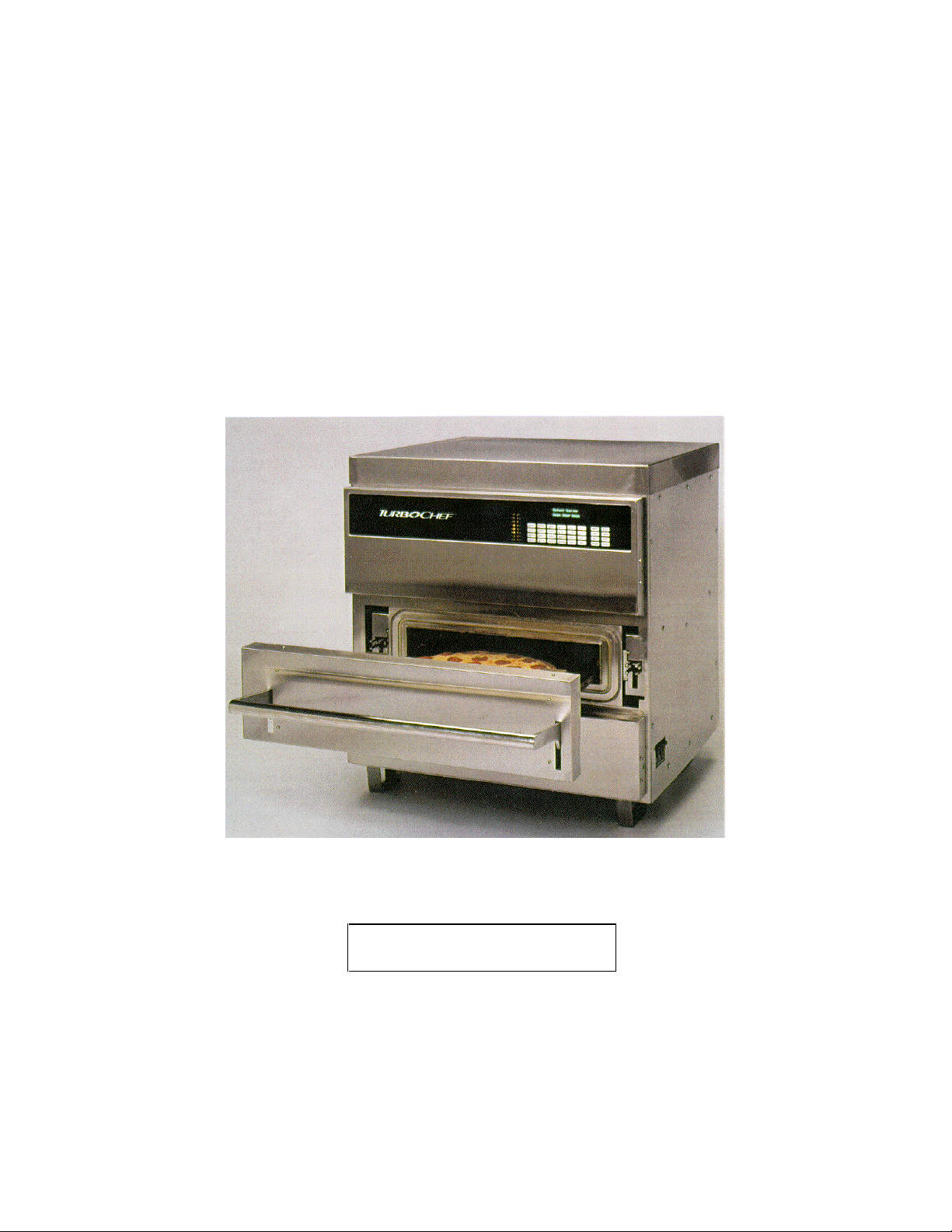
TurboChef Model D3 Ovens
See Inside for Important
Steps before Operating Oven.
Customer Service Toll Free Number (888) 992-6624
Copyright July 1, 1999
Blodgett Advanced Cooking Technologies® Inc., All Rights Reserved
P/N T0032 Rev A (2/00)
Page 2

TABLE OF CONTENTS
Contents Page
IMPORTANT SAFETY INSTRUCTIONS - READ FIRST.......................................... 4, 5
RF INTERFERENCE CONSIDERATIONS .................................................................... 6
GROUNDING INSTRUCTIONS.....................................................................................6
POWER CORD REPLACEMENT..................................................................................6
SECTION 1 - INSTALLATION
1.1 Model Identification and Rating........................................................................7
1.2 Installation Instructions..................................................................................... 7
1.3 Specifications................................................................................................... 8
1.4 Oven Assembly................................................................................................ 9
SECTION 2 - OPERATING INSTRUCTIONS
2.1 Glossary of Common Terms.......................................................................... 11
2.2 Basic Operating Instructions.......................................................................... 12
2.3 Other Oven Operations.................................................................................. 13
2.4 Developing Cook Settings and Programming ................................................ 15
2.5 Control Panel Layout......................................................................................20
SECTION 3 – CLEANING AND SELF TEST
3.1 Basic Cleaning Procedures - Care and Cleaning...........................................21
3.2 Maintenance Mode Troubleshooting..............................................................33
3.3 Self Test and On-Line Error Messages.......................................................... 35
3.4 Self Test Flow Chart....................................................................................... 37
3.5 On-Line Flow Chart........................................................................................39
SECTION 4 – CONVECTION SYSTEM
4.1 Blower Motor Assembly..................................................................................40
4.2 Blower Motor Controller Tests........................................................................41
4.3 Blower Defective Messages........................................................................... 41
4.4 Blower Motor Controller Defective Messages ................................................ 42
4.5 Blower Operation ...........................................................................................45
4.6 Blower Wheel Replacement...........................................................................46
4.7 Heat Exchanger .............................................................................................47
4.8 Ceramic Insulator Replacement.....................................................................49
4.9 Heat Exchanger Defective Messages............................................................50
SECTION 5 - MICROWAVE SYSTEM
5.1 Measuring Microwave Radiation Leakage......................................................51
5.2 How to Turn Magnetrons On/Off for Testing..................................................52
5.3 Microwave Component Locations..................................................................53
5.4 Microwave Error Messages............................................................................55
5.5 Magnetron...................................................................................................... 56
5.6 High Voltage (HV) Magnetron Transformers..................................................57
5.7 High Voltage Diode........................................................................................ 58
5.8 High Voltage Capacitor.................................................................................. 60
Page 3

5.9 Microwave Mode Stirrer................................................................................. 61
5.10 Magnetron Over-Temperature Switch............................................................ 61
5.11 RF Output Monitor Circuit...............................................................................62
5.12 Magnetron Power Verification........................................................................62
5.13 Waveguide Seal Installation...........................................................................64
SECTION 6 - COOK DOOR ASSEMBLY
6.1 Cook Door and Related Assemblies.............................................................. 66
6.2 Cook Door and Interlock Switch Adjustments................................................68
SECTION 7 - FILTER DOOR SWITCH LOCATION / ASSEMBLY..............................69
SECTION 8 - CONTROL
8.1 Electrical Enclosure Assembly.......................................................................70
8.2 Electrical Enclosure Diagnostic Message ...................................................... 71
8.3 Display and Keypad Assembly....................................................................... 71
SECTION 9 - MAG. FAN/COOLING FAN/TRANSFORMERS/DIODES/CAPS............ 72
SECTION 10 - TROUBLESHOOTING
10.1 Common Door Related Problems.................................................................. 74
10.2 Miscellaneous Problems................................................................................ 75
SECTION 11 - DIAGNOSTIC INFORMATION (INCLUDING SCHEMATICS)............. 77
SECTION 12 - LIMITED WARRANTY FOR “D” SERIES OVENS............................... 83
SECTION 13 – TECHNICAL APPENDIX
13.1 Appendix A – Oven Connection to Computer................................................ 84
13.2 Appendix B – Japanese Input Power Frequency Conversion........................85
13.3 Appendix C – Japanese Additional EMI Filter................................................ 86
13.4 Appendix D – T3 & T4 Filament Transformer 200-208 Voltage Selection...... 87
Page 4

IMPORTANT SAFETY INSTRUCTIONS
WHEN USING ELECTRICAL APPLIANCES, BASIC SAFETY PRECAUTIONS
SHOULD BE FOLLOWED, INCL UDING THE FOLLOWING:
WARNING - To reduce the risk of burns, electric shock, fire, injury to persons or
exposure to excessive microwave energy:
1. Read all instructions before using the appliance.
2. Read and follow the specific “PRECAUTIONS TO BE OBSERVED BEFORE AND DURING
SERVICING TO AVOID POSSIBLE EXPOSURE TO EXCESSIVE MICROWAVE ENERGY” found on
page 5.
3. This appliance must be grounded. Connect only to properly grounded outlet. See “GROUNDING
INSTRUCTIONS” found on page 6.
4. Install or locate this appliance only in accordance with the provided installation instructions.
5. Some products such as whole eggs and sealed containers - for example, closed glass jars - may
explode and SHOULD NOT be heated in this oven.
6. Use this appliance only for its intended use as described in the owner’s manual. DO NOT use
corrosive chemicals or vapors in this appliance. This type of oven is specifically designed to heat,
cook, or dry food. It is NOT designed for industrial or laboratory use.
7. Children SHOULD NOT use this appliance.
8. DO NOT operate this appliance if it has a dam aged cord or plug, if it is not working proper ly, or if it
has been damaged or dropped. See “POWER SUPPLY CORD REPLACEMENT” found on page 6.
9. This appliance should be serviced only by qualified service personnel
10. DO NOT cover or block any openings on the appliance.
11. DO NOT store this appliance outdoors. DO NOT use this product near water - for exam ple, near a
kitchen sink, in a wet basement, or near a swimming pool, and the like.
12. DO NOT immerse cord or plug in water.
13. Keep cord away; from heated surfaces.
14. DO NOT let cord hang over edge of table or counter.
15. DO NOT use a water jet for cleaning.
16. See “Basic Maintenance Procedures - Care and Cleaning” provided in this manual.
17. To reduce the risk of fire in the oven cavity:
a) DO NOT overcook food. Carefully attend appliance if paper, plastic, or other combustible
materials are placed inside the oven to facilitate cooking.
b) Remove wire twist-ties from paper or plastic bag in oven.
c) If materials inside the oven should ignite, keep oven door c losed, turn oven off, and disconnect
the power cord, or shut off power at the fuse or circuit breaker panel.
d) DO NOT use the cavity for storage purposes. DO NOT leave paper products, c ooking utensils , or
food in the cavity when not in use.
SAVE THESE INSTRUCTIONS
Page 4 of 87
Page 5

PRECAUTIONS TO BE OBSERVED BEFORE AND DURING
SERVICING TO AVOID POSSIBLE EXPOSURE TO
EXCESSIVE MICROWAVE ENERGY
1. DO NOT attempt to operate this oven with the door open since open-door operation
can result in harmful exposure to microwave energy. It is important not to defeat or
tamper with the safety interlocks.
2. DO NOT place any object between the oven front face and the door or allow soil or
cleaner residue to accumulate on the sealing surfaces.
3. Make the following safety checks on all ovens to be serviced before activating the
magnetron or other microwave source, and make repairs as necessary:
a) Interlock operation.
b) Proper door closing.
c) Door (bent).
d) Hinges and latches (broken or loosened).
e) Door seals and sealing surfaces (arcing, wear, and other damage).
f) Evidence of dropping or abuse.
4. Before turning on microwave power for any service test or inspection within the
microwave generating compartments, check the magnetron, wave guide, or
transmission line, and cavity for proper alignment, integrity, and connection.
5. Any defective or mis-aligned components in the interlock, monitor, door seal, and
microwave generation and transmission systems must be repaired, replaced, or
adjusted by procedures described in this manual before the oven is released to the
owner.
6. The oven SHOULD NOT be adjusted or repaired by anyone except properly
qualified service personnel.
7. A microwave leakage check to verify compliance with the Federal Performance
Standard MUST BE performed on each oven prior to release to the owner.
SAVE THESE INSTRUCTIONS
Page 5 of 87
Page 6

RF INTERFERENCE CONSIDERATIONS
This oven generates radio frequency signals. This device has been tested and
determined to be in compliance with applicable part of FCC part 18 requirements and to
the protection requirements of Council Directive 89/336/EEC on the approximation of
the laws of the Member States relating to electromagnetic co mpatibility at the time of
manufacture. However, some other equipment may exhibit sensitivity to signals below
these limits resulting in interference with that equipment.
If your equipment experiences interference, the following steps should be considered:
1. Increase the physical separation between this oven and the sensitive equipment.
2. If the sensitive device can be grounded, do so following accepted grounding
practices.
3. If battery powered microphones are being affected, insure that the batteries are fully
charged.
4. Keep sensitive equipment on electrically separate circuits, if possible.
5. DO NOT route intercom wires, microphone wires, or speaker cables near oven.
GROUNDING INSTRUCTIONS
This appliance MUST BE grounded. In the event of an electrical short circuit, grounding
reduces the risk of electric shock by providing an escape wire for the electric current.
This appliance is equipped with a cord having a grounding wire with a grounding plug.
The plug must be plugged into an outlet that is properly installed and grounded.
WARNING - Improper use of the grounding can result in a risk of electric shock.
Consult a qualified electrician or serviceman if the grounding instructions are not
completely understood, or if doubt exists as to whether the appliance is properly
grounded.
DO NOT use an extension cord. If the power supply cord is too short, have a qualified
electrician or serviceman install an outlet near the appliance.
POWER SUPPLY CORD REPLACEMENT
If the power supply cord is damaged, it MUST BE replaced by the manufacturer or its
service agent or a similarly qualified person in order to avoid a hazard.
SAVE THESE INSTRUCTIONS
Page 6 of 87
Page 7

SECTION 1 - INSTALLATION
1.1 MODEL IDENTIFICATION AND RATING
MODEL NUMBER, NAMEPLATE INFORMATION AND SERIAL NUMBER is
located on the nameplate label on the rear cover of the oven.
NOTE: An electrical schematic is supplied with the oven. It is located in the
back of the Display Panel in an envelope. Please return the schematic to
the storage envelope for future use.
SERIAL NUMBER IDENTIFICATION is located on a serial number label
attached underneath the lower right corner of the oven frame and on the rear
cover.
CAUTION: It is extremely important that the model number be correctly
identified. Electrical wiring and program changes have been made to the
D3 oven. Information from earlier D models must not be applied to the D3
model. Use information from this manual only.
Wiring Information:
• European D3 models require a three phase WYE 5 wire power cord. This
oven must not be operated on three phase DELTA or single phase
power.
• North American and Japanese three phase D3 ovens require a three phase
DELTA 4 wire power cord. This oven must not be operated on three phase
WYE or single phase power.
• North American single phase D3 ovens require a 3 wire power cord. This
oven must not be operated on three phase power.
1.2 INSTALLATION INSTRUCTIONS
1.2.1 Installation Requirements
The installation must be made in conjunction with an understanding of applicable
CE, UL, cUL, NSF, and FDA requirements and appropriate local codes.
Before starting installation, the owner/installer should understand and agree
upon:
a) The installation policies of TurboChef Technologies Inc.
b) The installation plan based on overview and preparation.
c) The responsibility for testing, instruction of proper operation, use & care, and
preventative maintenance.
WARNING
a) DEATH, INJURY, AND EQUIPMENT DAMAGE could result from improper
installation of the TurboChef oven or installation of a unit which has been
damaged during shipment or storage. Either of these conditions could void the
equipment warranty.
b) DO NOT INSTALL a TurboChef oven suspected of damage.
c) INSTALL the TurboChef oven according to the policies and procedures outlined
in this manual.
Page 7 of 87
Page 8
1.2.2 Installation Precautions
(FRONT)
This equipment is designed and manufactured to comply with applicable CE, UL,
cUL FDA, and FCC requirements. In addition, the unit is UL classified to NSF 4.
All equipment is designed and certified for safe operation when installed in
accordance with local and or national codes. Many local codes exist, and it is the
responsibility of the owner and installer to comply with these codes.
In no event shall the manufacturer assume any liability for damages or injury
resulting from installations which are not in compliance with the instructions and
codes listed above. The manufacturer shall not assume liability for damage or
injury resulting from improper installation of equipment including temporary or
unstable work stations or counter tops.
The counter top or work surface must be able to support the weight of 650
pounds and should not exceed 30 inches in height.
There must be 1.75” (4.4cm) between the top of the unit and any shelf or
surface.
The oven must be level front to back and side to side. The oven legs may be
bolted to the counter top and must be bolted if it is placed on a rolling cart.
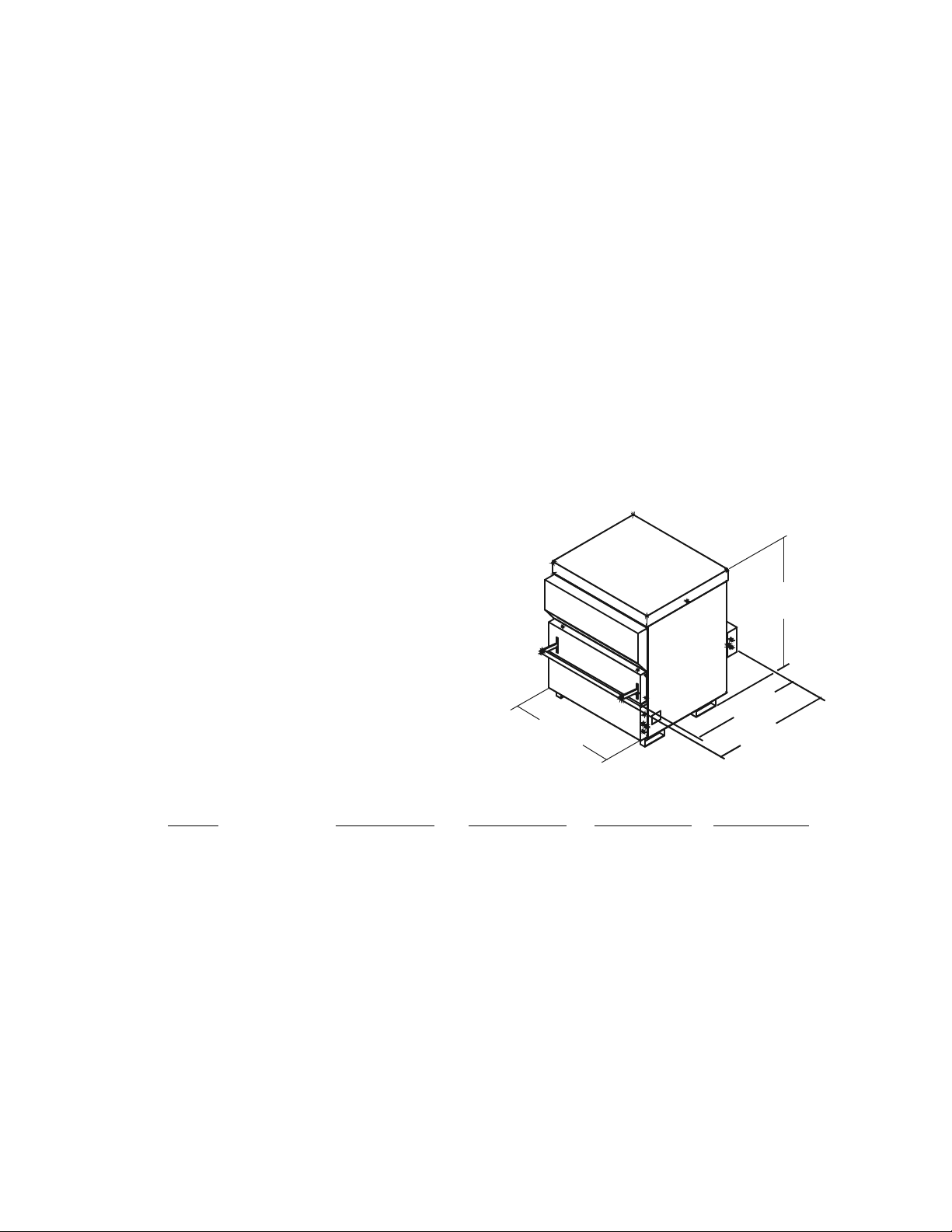
1.3 SPECIFICATIONS
Physical characteristics:
Width: 31.5” (80cm)
Height: 40.0” (101.6cm)
Depth: 35.3” (89.6cm)
(Door handle closed)
37.0” (94.0 cm)
(Door handle up)
Weight: 540 lb. (1190.7kg)
31.5”
(80cm)
(101.6cm)
35.3”
(89.6cm)
37”
(94cm)
40”
Electrical Characteristics:
North American European Japanese
Model D3-A-5/6D4 D3-S-5/6S3 D3-E-5/6Y5 D3-J-5/6D4
Voltage: 208/240 V 208/240 V 400-415 V 200 V
Frequency: 50/60 Hz 50/60 Hz 50/60 Hz 50/60 Hz
Connections*: 3Φ, 4 wire 1Φ, 3 wire 3NΦ, 5 wire 3Φ, 4 wire
Current: 30/33 Amps 50 Amps 18 Amps 32 Amps
Max Power Usage:
Convection Oven: 7.0/9.0 kW 7.0/9.0 kW 9.0 kW 6.5 kW
Microwave Oven: 4.0 kW 4.0 kW 4.0 kW 4.0 kW
Microwave Freq.: 2450 MHz 2450 MHz 2450 MHz 2450 MHz
Connector Type: NEMA 15-50P NEMA 6-50P IEC 309-32A NEMA 15-50P
* connections including ground
The oven is supplied with a 6’ power cord that includes a male connector. The
outlet box, receptacle and wall plate are to be furnished by the installing
contractor.
Page 8 of 87
Page 9
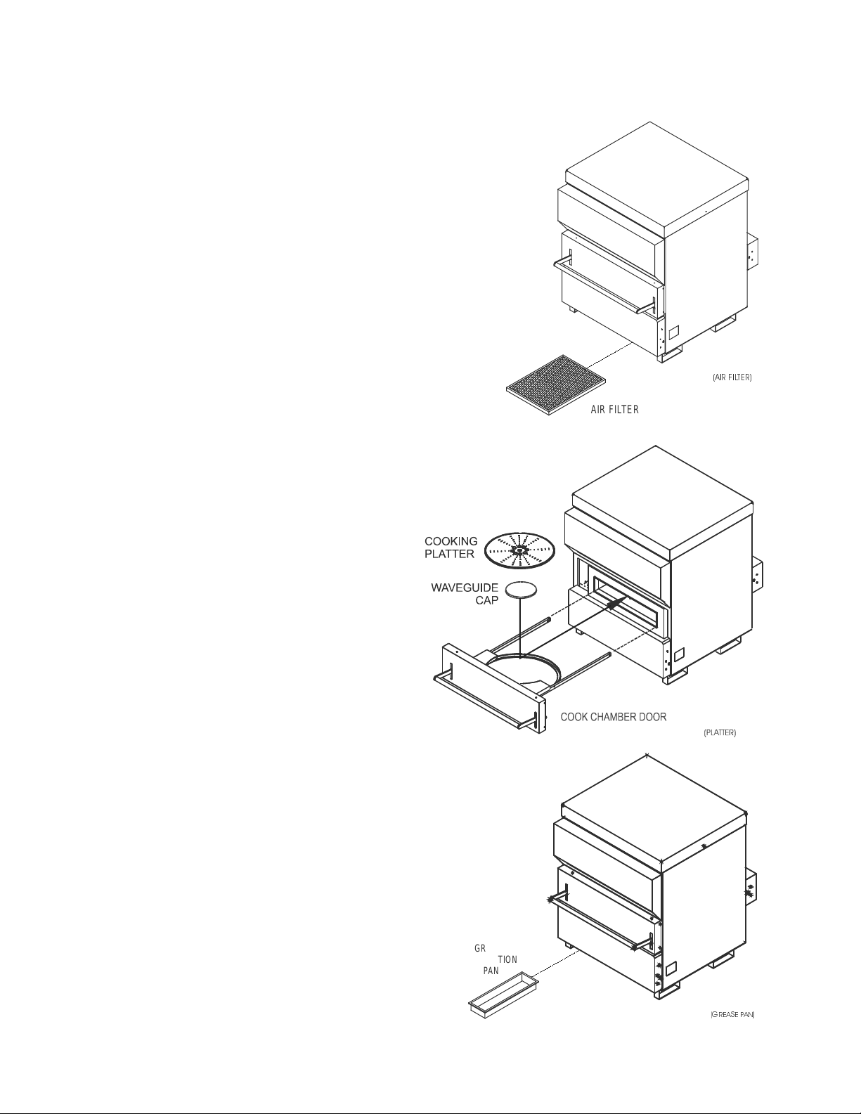
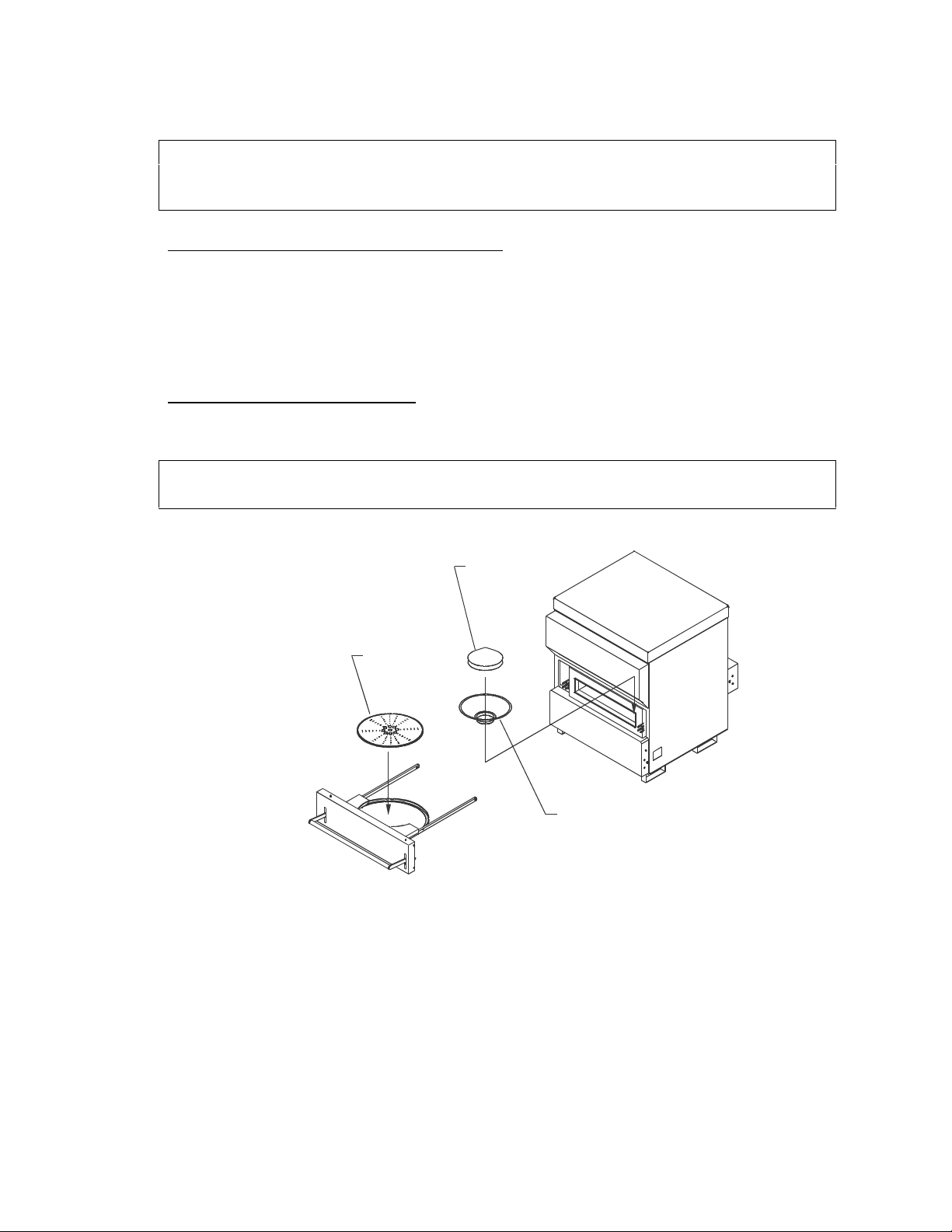
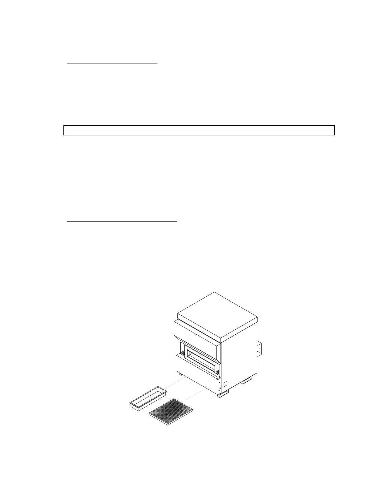
1.4 OVEN ASSEMBLY
AIR FILTER
Air Filter and Frame
1. Remove the air filter and frame from their
shipping location on the back of the unit.
2. Slide the air filter frame into the brackets
on the bottom of oven below the cooking
chamber. Secure the frame to the bottom
front of the unit with a thumbscrew.
3. Slide the air filter into the frame.
Ceramic Cooking Platter
1. Carefully remove the packing
material from the ceramic
Cooking Platter.
$,5),/7(5
2. Open the cooking chamber
door.
3. Place the cooking platter onto
the ring in the cook chamber
door.
Waveguide Cap
1. Place the waveguide cap
centered on top of the screen
basket.
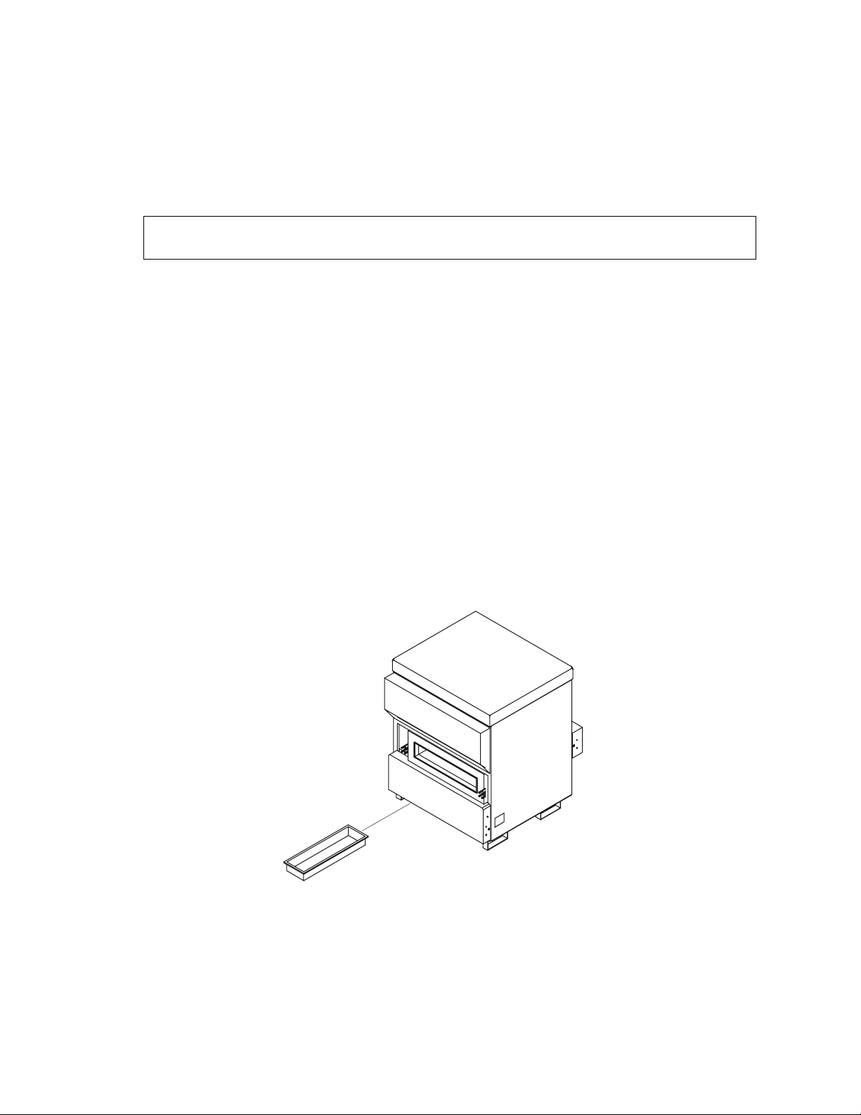
Grease Pan
1. Slide the grease pan into the frame
on the bottom left side of the oven.
Position the grease pan with the
weep hole to the front of the oven.
GREASE
COLLECTION
PAN
*5($6(3$1
Page 9 of 87
Page 10

Cart (if applicable)
1. Lift the oven onto the cart. The holes in the top frame of the cart should line
up with the holes in the base supports of the oven.
2. Secure the oven to the cart as follows:
a) Place a washer, lock washer and nut on the bolt and tighten. DO NOT
over tighten or the cart’s tubing will become deformed.
b) Repeat for each leg
Additional Consumable Parts
These additional parts are to be used as spares. They should not be installed in
the oven at this time.
Part Number Description Quantity of Spares (US only)
T100532 Grease Filter 3
T7000301 Ceramic Cooking Platter 2 + 1 (included with oven)
T7000302 Waveguide Cap 2 + 1 (included with oven)
T7001189 Chamber Basket 1
Page 10 of 87
Page 11

SECTION 2 - OPERATING INSTRUCTIONS
2.1 GLOSSARY OF COMMON TERMS
Air - Percent of convection air flow during a cook event.
Cook Temperature Set Point - The constant parameter, Cook Temperature Set
Point, is used by all Cook Settings.
Cook Chamber - Cavity in which the food products are cooked.
Cook Cycle - Time of operation for a Cook Setting.
Cook Setting Recipe - The food product cooking process. It consists of
duration, percentage of the hot air flow (AIR) required and microwave (TW)
required.
Cook Mode - Execute the Cook setting instructions for selected food product.
Cooking Product - The food product to be cooked in the oven.
Cook Event - Segment of a cook cycle, up to 4 events can be used for each
cycle.
COOL-DOWN Mode - Turns OFF all oven components except the cooling fan.
Display - Primary interface to relay messages to the operator.
Duration - Time, in seconds, of a single cook event.
EDIT Mode - Mode used to adjust the Cook Setting parameters.
Keypad - Primary interface for the operator to control the oven.
HEAT - Selects the cook temperature set point in EDIT mode.
LED - Individual light indicators numbered 1 through 16 to show component
status.
MAINTenance Mode - Mode used by authorized service personnel to check the
operation of oven components.
Mode - The software environment which allows certain operations to occur.
There are several modes, NORMAL, COOK, SELF-TEST, EDIT, WARM UP,
COOL DOWN and MAINTenance, in which the oven can operate.
NORMAL Operation Mode - Mode used to perform the "NORMAL" oven
operations, such as, monitor the key pad for requests to cook or change mode,
and maintain the oven at the Cook Temperature Set Point.
Parameter - A Cook Setting consists of two different kinds of parameters. Those
which stay constant during a Cook Setting execution and those which can vary
during different events of a Cook Setting.
Radio Frequency (RF) - The term used to describe the microwave emissions.
Recipe - Cook Setting. The food product cooking plan. It will consist of up to four
Cook Events, each of which consists of duration, percentage usage of the hot air
flow (AIR) required and microwave (TW) required.
RESUME - Continues Cook Cycle if interrupted such as by opening oven door.
TW - Percent of Microwave used during a Cook Event.
WARM-UP Mode - Brings the oven up to the Cook Temperature Set Point.
SELF-TEST Mode - Self checks all critical components (magnetrons, heat
exchanger and blower are operational.
Page 11 of 87
Page 12

2.2 BASIC OPERATING INSTRUCTIONS
2.2.1 Power On
The power switch is on the right side, lower front when your are facing the oven.
Pull the power switch toward the top of the oven to energize.
2.2.2 Self Test/Warm Up
1. The machine will go through a self-check to verify that the critical components
(magnetrons, heat exchanger and blower) are operational. (If the oven
displays the message “Cooling Down”, Depress the “Warm Up” key to start.)
CAUTION: Self Test results are unpredictable if the oven door or filter
door are not closed prior to or opened during the self test.
2. If any of the critical components are malfunctioning, the machine will stop at
the end of the test displaying a message identifying the faulty component.
Refer to Troubleshooting Section for message definition. To continue press
Stop.
3. When the self-check is complete and satisfactory, the machine will start
warming up and display "WARMING UP, HX Temp …". The HX Temp is the
temperature of the heat exchanger. When the HX temperature exceeds a
value determined by the cook temperature set point, the blower begins
circulating air and the display indicates “CC Temp/HX Temp” on the lower
line. The CC Temp is the temperature in the oven cook chamber. When the
CC temperature reaches the cook temperature set point, warm-up is
complete. The Warm Up should take approximately 30 minutes (shorter if the
machine has not cooled down completely).
4. When the oven is ready to cook, it will display:
Select Recipe Or Select Recipe
CC 480° HX 571° If in Diagnostic Mode Heat 480/571°
2.2.3 Running A Recipe/Cook Setting
CAUTION: DO NOT operate the oven without food or a suitable microwave
load in the cook chamber. This may damage the oven.
CAUTION: DO NOT operate the oven with metal in the cook chamber. This
will damage the oven.
1. Open cooking chamber door by pulling the handle up, then pull the handle
outward until the door opens.
2. Place the food product in the appropriate position on the cooking platter.
3. Close cooking chamber door by pushing forward on the handle until the door
shuts, then push the handle down to latch into place.
4. Press the desired food (group) Cook Setting button.
Page 12 of 87
Page 13

5. Press a button numbered 1 to 6 (subgroup) for food quantity or special food
definition. The display indicates the food group/subgroup name and cook
time seconds (counting down).
6. W hen the cooking cycle is complete, the oven will beep and the display will
indicate "PLEASE REMOVE FOOD FROM OVEN". Remove the food product
from the oven.
Note: Food will continue to cook with radiant and convection
energy when left in the oven due to the high cook chamber temperature.
7. The cook cycle is now ready to begin again.
Notes:
• If for any reason you want to stop the cooking cycle, press the “STOP” button
at any time. The user may close the door and press "RESUME" for the Cook
Setting to continue.
• If the oven door or filter door is opened during a cook cycle, the oven will
automatically stop the current Cook Setting. The user may close the door and
press “RESUME” for the Cook Setting to continue.
• If the “DARKER” key is depressed, 25% of the last cooking event is added as
additional cook time.
• Protection against exposure to microwave energy: Safety interlocks in the
oven doors prevent or terminate microwave operation when either the oven
door or filter door is open.
2.2.4 Power Off
The power switch is on the lower right side, near the front when facing the oven.
Push the power switch toward the bottom of the machine to de-energize.
2.3 OTHER OVEN OPERATIONS
2.3.1 Cool Down
An alternative to turning the power switch OFF when cooking is finished for the
day is the "COOL DOWN" mode. This mode turns off all the major components
but still allows the cooling fan to operate to keep the internal temperatures of the
oven electrical parts down while the oven is cooling. To select "COOL DOWN"
press the "COOL DOWN" button followed by the "ENTER" button. Opening the
oven door will shorten the cool down time.
2.3.2 Warm Up
To remove the oven from "COOL DOWN" and return to the ready to cook state,
press the "WARM UP" button. Make sure the oven and filter doors are securely
closed. Remember, the oven may take up to 30 minutes to warm up.
2.3.3 Stop Key
The "STOP" key can be utilized to stop the Cook Setting at any point in the
cook cycle. The Cook Setting may be continued by pressing the "RESUME"
key. The "STOP" key is also used to exit other modes such as "EDIT" or
"MAINTENANCE".
Page 13 of 87
Page 14

2.3.4 Darker Key
The "DARKER" key may be used to cook the food an additional 25% of the last
cooking event. This may be useful to brown the food product or make the
product well done.
2.3.5 Resume Key
The "RESUME" key allows a Cook Setting which was interrupted by the "STOP"
key or opening the oven door to continue.
2.3.6 MAINTenance, Edit, and Heat Keys
Described in the section on Developing Cook Settings and Programming.
2.3.7 Catalytic Converter
The catalytic converter, T7001197, is installed in the return air duct downstream
of the grease filter assembly. The installation of the catalytic converter requires a
catalytic converter support frame, part # T7001195, to properly position it in the
air path. The above parts may be ordered in kit form, # T7001200.
Operation and Indication of Problems
Due to the nature of most foods and the physics governing the operation of the
TurboChef Oven, grease buildup downstream of the cooking chamber is
inevitable. Strict cleaning regiments can solve a majority of the problems,
however, recirculation of undiluted grease saturated air that is the main cause of
downstream grease accumulation and any associated residual flavors.
The airborne grease will tend to collect and bake onto the oven surface
downstream of the cooking chamber. This grease, due to the high operating
temperatures of the oven, will start to rapidly decompose into derivative organic
compounds.
These decompositional derivatives generally have positive and negative effects
on cooking; the shorter chain derivatives add favorable flavor characteristics to
the food, while the higher order carbon chains lend unpleasant flavor
characteristics, such as bitter tarry tastes.
The installation of the catalytic converter greatly effects the grease handling and
any residual flavors which might build up over time. A properly operating catalytic
converter causes the conversion of airborne grease into water, carbon dioxide
and small amounts of nitrogen and oxygen. The catalytic converter acts as a
combustion chamber for the airborne grease. The catalysts present on the filter
lowers the ignition temperature of the airborne grease from approximately 7000F
to 450-5500F, allowing combustion to occur. The operating temperature of the
oven directly determines the percentage of airborne grease conversion. A single
pass of the air stream yields a 20-30% improvement in air quality.
A problem with the catalytic converter is indicated by a decrease in the
effectiveness of browning (caused by a reduction in airflow) or by flavor transfer
from one food group to another. Your operating parameters (daily use and oven
run time) determines inspection/cleaning frequency. See cleaning instructions for
procedure.
Page 14 of 87
Page 15

2.4 DEVELOPING COOK SETTINGS AND PROGRAMMING
2.4.1 How to Develop your Cook Settings
Cooking with a TurboChef oven is different and exciting! It delivers hot food
faster, at a higher quality than other ovens available today.
TurboChef uses both hot air and microwave energy to cook food. If you have
experience with either a convection oven or microwave oven you will see
similarities and significant differences. The key to creating good cook settings for
your food is to understand the following rules:
1. TurboChef uses a moving shroud of hot air to surround the food. This locks in
the food’s moisture.
2. The hot air provides most of the heating and browning of foods. The higher
the air velocity, the faster heat energy is transferred to food.
3. The microwave provides heat to the center of the food. Don’t try to do all the
cooking with microwave!
4. The weight of food determines the total time required to cook. The more
weight, the longer the time required. (Most medium thick crust pizzas cook in
about 100 seconds.)
5. Thick and dense foods may need to be flipped half way through the cooking
cycle.
6. Microwave works best in the early stages of cooking, then use hot air to finish
the cooking.
7. Color develops mostly at the end of the cooking cycle. Higher velocity air in
the later stages of cooking will strongly control the food’s color.
Don’t be afraid to experiment! Write down your current cook settings and then
start testing. You can always go back to the old cook settings in a few seconds.
Enjoy the power and flexibility of your TurboChef System.
2.4.2 Reviewing Existing Cook Settings
1. Press the EDIT key, key in the Access Number (PIN) and press ENTER.
2. Press the Recipe GROUP key you wish to review and observe the group
name.
3. Press ENTER.
4. Press a SUBGROUP key, key 1 through key 6, and the subgroup name
appears to the right of the GROUP name.
5. Press ENTER and observe the Duration in seconds, the percentage of hot air
flow (Air), and the percentage of microwave (TW) for the first event of the
cook cycle.
Page 15 of 87
Page 16

6. Press ENTER and the second event parameters are displayed. The Cook
Setting ends when an event with zero time duration is encountered or all four
events are used. If the first event of a Cook Setting has a duration of zero
time, no Cook Setting is defined.
7. Press EDIT to return to step 2.
8. Press HEAT and observe the cook temperature set point. The cook
temperature set point applies to all GROUP/SUBGROUP cook settings.
9. Press STOP to return to normal operation.
2.4.3 E diting Cook Settings
1. Press the EDIT key, enter Access Number (PIN) and Press ENTER.
2. Press the Recipe GROUP name key of the Cook Setting you wish to edit.
3. Edit the food group name using the left/right arrow keys to position the
blinking cursor. Nine characters are available for the food group name.
Repeat pressing an alpha/numeric key until the needed letter or number
appears. The up/down arrow keys select upper case or lower case letters.
Use the right arrow key to advance to the next character position. The SP key
replaces a character with a space and advances to the next character
position. Press ENTER when the new name is complete. Note: When the
existing information is correct, simply press ENTER to store the information
and move to the next display.
4. Press a SUBGROUP key number, 1 through 6, to indicate quantity or special
food definition.
5. As described in Step 3, likewise edit the subgroup name. Press ENTER.
6. Observe the three parameters for cook event 1. The blinking cursor indicates
the Event Duration is selected for editing. Use the left/right arrow keys to
select the other parameters, blower power (AIR) or microwave power (TW).
7. Using the numeric section of the keypad, key in the correct time or
percentage and press ENTER. The blinking cursor will advance to the next
parameter. Note: You must press ENTER to replace previous settings with
new settings. Be careful not to change a setting and move the blinking cursor
without pressing ENTER to save the setting.
8. If a setting is not changed and ENTER is pressed, the display will advance to
the next event. Use the up/down arrow keys to select any of the 4 events to
edit or review.
9. W hen 4 events are not required for the cook setting, set the duration of the
first unused event to 0. Note: If the duration of event #1 is set to 0, the
GROUP/SUBGROUP selection has no cook setting and displays “NO
RECIPE ENTERED” when selected.
Page 16 of 87
Page 17

10. Valid event duration time is 1 to 255 seconds. However, the combined
duration of all events, i.e., the total Cook Setting cook time, should not
exceed 999 seconds. Valid blower power (AIR) is 20% to 100% in 5%
increments. Valid microwave power (TW) is 0%, 50%, or 100%.
11. Anytime you wish to select a different Cook Setting to edit, press EDIT and
return to step 2.
12. To review or edit the Cook Temperature Set Point, press HEAT. Enter a new
temperature from the numeric keys and press ENTER. Note: The same Cook
Temperature Set Point applies to all GROUP/SUBGROUP Cook Settings.
13. When editing is complete, press STOP to return to normal cook mode.
2.3.4 Maintenance Operations
The MAINTenance mode allows you to manually control the various hardware
components of the oven and display operational information
Press the MAINTenance key, enter access number (PIN) and press ENTER.
1. VER key alternately displays the version of the oven operating system
(hardware and software) and the oven recipe version if loaded by the
ChefComm utility.
2. HTR key turns the Heat Exchanger On and Off. If the heat exchanger is over
the maximum allowed temperature (Approximately 700 degrees F), the
heaters can not be turned on. An over temperature thermostat also prevents
heater runaway. LED 11 indicates heaters are selected and LED 16 indicates
current is flowing to the heaters. This key also resets the COOK TEMP TOO
LOW message.
CAUTION: DO NOT leave the heaters on for long periods, as the oven will
rapidly heat to maximum allowed temperature (Approximately
720qF(382qC).
3. %BLO key increases the convection airflow in 10% increments. Repeat
pressing key to select new air speeds. When the airflow is 100%, the next
key press resets airflow to 0%. If the blower is Off (LED 7 is no t illuminated)
the %BLO key is ignored.
4. BLR key turns the convection air blower On or Off. LED 7 indicates the status
of the blower motor speed controller. The blower will return to controlled
operation when MAINTenance is exited. This key also resets the BMSC
DEFECTIVE message.
Page 17 of 87
Page 18

5. M12 key energizes both magnetron 1 and 2 when the key is held depressed.
There will be a 3 second delay while magnetron filaments heat up initially.
The filaments will stay on for 3 minutes after the end of the last time the
magnetrons were energized. To conserve power, the Heat Exchanger is
turned OFF when the key is pressed. The display provides an un-calibrated
indication of the power level in the microwave waveguide cavity. The power
reading varies with the motion of the microwave stirrer blade. The magnetron
turns OFF when the key is released. This key also resets the Mag RF FLUC
LO, Mag CURRENT LOW and Mag THERMO SW messages.
CAUTION: DO NOT hold the key more than 5 seconds without a cooking
product or suitable microwave load in the oven.
6. PIN key allows for entry of an alternate personal identification number for
accessing EDIT and MAINTenance modes. If ChefComm is implemented, the
PIN will also reset the “New Settings” message. Enter from 1 to 4 n umbers or
letters and press ENTER. Be sure to keep a record of the PIN you choose.
7. CCC key displays the Cook Cycle Count. Press key a second time and a
message prompts to press SP/CLR to reset the count to zero.
8. EC key displays the temperature of the electronics compartment. If the EC
thermocouple is open or missing, “EC THERMO OPEN” is displayed. The EC
temperature should not exceed 140°F(60°C) under normal conditions.
9. WARM key causes the MAINTenance mode to be exited and the WARM-UP
mode to be selected without executing SELF-TEST.
10. DIAG key performs two functions. The first press displays the heat exchanger
rate of temperature rise, degrees per minute. This number is used by the
oven operating system to replace heat lost during cooking and maintain cook
temperature when the oven is idle. If MAINTenance mode is exited after the
first press, a diagnostic display is presented during cook and heat
maintenance cycles. The display shows all parameters, RF power, percent
airflow, CC and HX temperature, and the accumulated and target BTU during
cooking for each event.
The second press indicates if the temperature rise was measured or
defaulted to the last known measurement. The measurement is taken during
oven warm up when the initial cook chamber temperature is less than one
half the cook temperature set point. To keep the normal display, exit
MAINTenance after the key press showing the measured or default message.
11. IAF key selects the amount of air flow when the oven is idle (not Cooking).
When IAF is first pressed, the current Idle Air Flow is displayed. The IAF
range is 0% to 50% in 5% increments. Repeat pressing the IAF key to select
a new air flow. Then press ENTER to set the new IAF.
Page 18 of 87
Page 19

12. SN key is used to enter the oven serial number. The first time SN is pressed
the current serial number is displayed. A second press clears the serial
number field and awaits entry of a new number. Up to 14 alpha/numeric
characters may be entered. Repeat pressing an alpha/numeric key until the
needed letter or number appears. Use the right arrow key to advance to the
next character position. The left arrow key moves the cursor to the left to
permit changing a previously entered character. The SP key replaces a
character with a space and advances to the next character position. The
serial number is updated when ENTER is pressed.
13. FF key is used to display and reset oven fault flag counters. Repeat pressing
the FF key to display the 6 faults, BMSC Status, Low Cook Temperature, Low
Mag Current, Low RF Fluctuation, Mag Thermo Switch, and EC Over
Temperature. The counters increment from 0 to 255 and roll over to 0. To
reset a counter, repeat pressing FF to select the fault and press SP/CLR.
14. F/C key is used to select Fahrenheit (ºF) or Celsius (ºC) temperature scale for
the display. If Fahrenheit temperature is currently displayed, pressing F/C will
change the display to Celsius and visa versa.
15. MS key is used for modem selection when the oven is connected via
telephone to a remote ChefComm facility. Refer to document T700155 for
ChefComm operation.
Press the MAINTenance or STOP key to return to normal cooking operation. The
magnetrons and heaters are turned OFF, the blower controller is returned to the
ON or operational state and the air flow is set to the IAF setting bef ore returning
to normal cooking operation.
2.4.5 Replacing Keypad Menu Label Strips
1. Remove menu label strips by inserting a small pointed object, such as a
wooden toothpick, under the keypad film and pull out until the strip appears
and can be removed by hand. Use caution in order to avoid damaging keys,
cutting the keypad film or scratching the stainless steel panel.
2. Install a new menu strip by holding the keypad slot open with a small pointed
object and sliding the new menu strip into place. Again, use caution to avoid
cutting the keypad film or scratching the stainless steel panel.
Page 19 of 87
Page 20
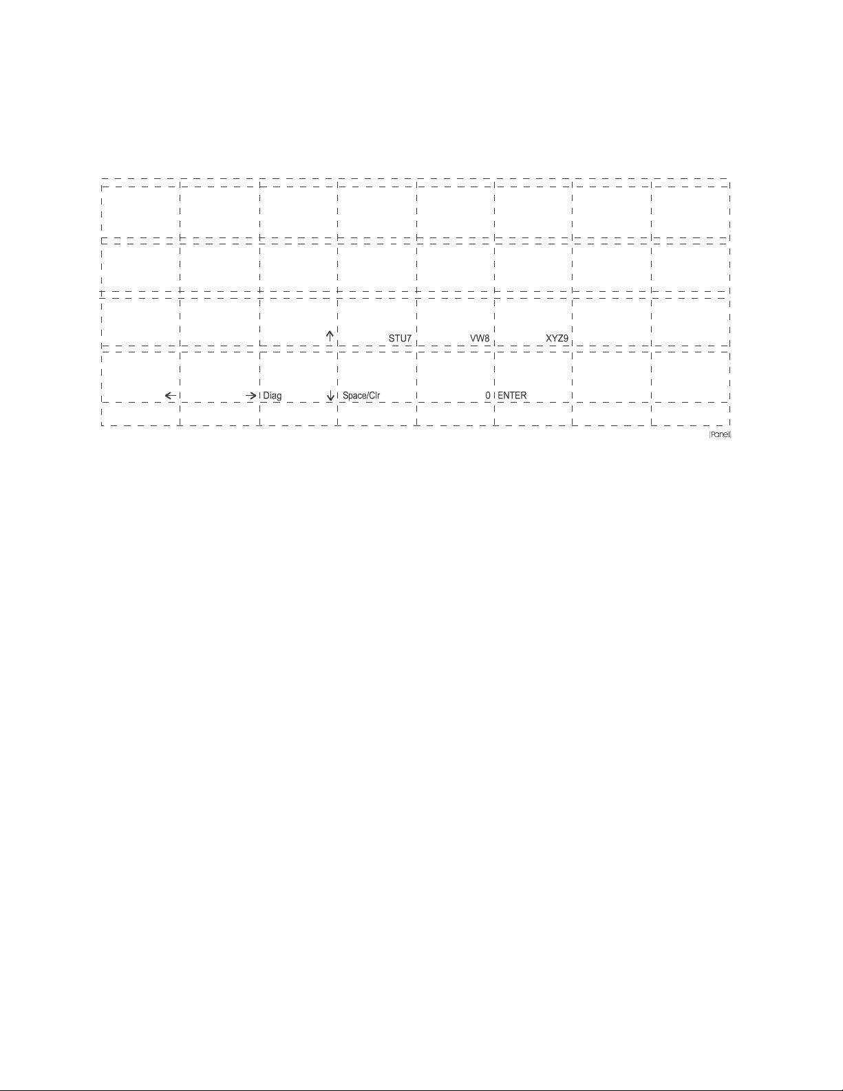
2.5 CONTROL PANEL LAYOUT
/#+06
2.5.1 Keypad Layout
NOTE: Subscripts used in MAINTenance and EDIT modes only.
#
Ver
$
Htr
%
%Blr
&
Blr
2.5.2 Status LED Indicator Layout
Cook Door Primary 1
Cook Door Secondary 2
Cook Door Monitor 3
Filter Door Primary 4
Filter Door Secondary 5
M12
Pin
'
(
)
*
CCC
EC
,
.
/
IAF ABC1
JKL4
0
/+%41
••
••
••
••
••
SN DEF2
FF MNO5
2
/+%41
#+4
°C/°F
9
10
11 Heat Exchanger
12 Magnetron 1 Temperature OK
13 Magnetron 2 Temperature OK
MS GH13
PQR6
4
#+4
'&+6
*'#6
%11.
&190
5612
9#4/
72
-'4
4'57/'
3DQHO
Filter Door Monitor 6
Blower Running 7
When light is on, item is active.
••
••
8
••
14 Magnetron 1 On
15 Magnetron 2 On
16 Heat On
Page 20 of 87
Page 21

SECTION 3 – CLEANING AND SELF TEST
3.1 BASIC CLEANING PROCEDURES - CARE AND CLEANING
Carbon and grease build-up will adversely affect the cooking performance
and life expectancy of certain components of the TurboChef oven. It is the
operator’s responsibility to properly maintain this unit. Failure to maintain
this unit in a clean condition will void the warranty.
WARNING: Never use a NaOH (Lye) based chemical to clean the
Turbochef oven. Use of NaOH (Lye) based chemicals can damage critical
components and will void the warranty.
3.1.1 SUPPLIES NEEDED
•
Non-Lye Non-Caustic Oven Cleaner
•
Non-Lye Non-Caustic Degreaser
•
All Purpose Cleaner
•
Oven Coating (optional) To more easily maintain a clean oven (especially
back wall of cooking chamber), grease shield oven coatings may be applied,
after oven has been cleaned
NOTE: For a specific listing of non-caustic, non-lye cleaning products,
call your local Authorized Service Provider.
3.1.2 CLEANING EQUIPMENT
•
Nylon 3x5 green scrub pads
•
Dry, clean towels
•
Sheet pan
•
Firm bristle brush (6-8 inch handle with 2x2x1 bristles)
•
Bottle brush – small (3 inch test tube diameter),
•
Protective rubber gloves,
optional
optional
Page 21 of 87
Page 22

3.1.3 DO’S AND DON’TS OF CLEANING
DO – Keep the oven clean. Daily cleaning is recommended.
DO – Be careful when cleaning the oven. Surfaces stay hot for a long time.
DO – Switch the oven off at the circuit breaker before cleaning.
DO – Thoroughly wipe all surfaces that come in contact with oven cleaner with a
damp sponge or cloth.
DO – Remember oven door is heavy. Use two people to remove and replace.
DO – Change the grease filter if it is holed or clogged.
DO – Put grease filter back in the correct way.
DO – Clean bottom air filter weekly.
DO – Clean ceramic platter with a non Lye based cleaner then rinse off and dry.
DO – Clean ceramic wave guide cap with a non Lye based cleaner then rinse off
and dry.
DO NOT – Place hot ceramics on cold surfaces.
DO NOT – Allow ceramics to soak in any liquid for any period of time.
DO NOT – Remove any panels from the oven (except lower access panel).
DO NOT – Allow water to be forced up into the air holes in the roof of oven.
DO NOT – Allow build up of grease or carbon on any surface in the oven.
DO NOT – Spray LYE BASED oven cleaners into the oven.
DO NOT – Use metal objects to clean the oven. (Other than scraper used for
hard to remove carbon and debris in weekly / monthly cleaning).
DO NOT – Spray non-caustic oven cleaners, degreasers, and grease shield
products or any other liquid onto the wave guide seal.
DO NOT – Scrub the wave guide seal.
DO NOT – Throw the grease filter frame assembly away.
DO NOT – Spray grease shield products on the catalytic converter
DO NOT – Bang catalytic converter on a hard surface to clean
Page 22 of 87
Page 23
3.1.4 MINIMUM DAILY CLEANING PROCEDURE
CAUTION: Before cleaning turn the unit off at the unit’s power switch,
then turn off main power supply breakers! (Power switch is located on the
right side panel at lower front corner)
STEP 1: Preparing the oven for cleaning
1. Turn off power at the switch. Disconnect the power supply.
2. Open the oven door.
3. Allow the oven to cool for a minimum of 45-60 minutes to ensure safe
handling.
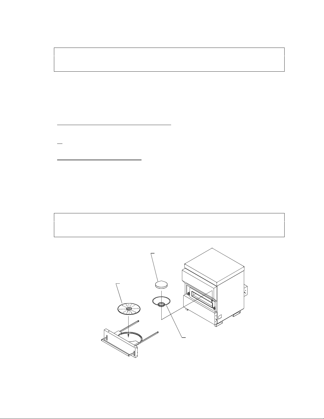
STEP 2: Cook Chamber parts
Carefully remove the cooking platter, chamber basket and ceramic
waveguide cap. Set aside.
CAUTION: Handle the Ceramic Cook Platter and Wave-guide Cap carefully
to avoid breakage.
CERAMIC
WAVEGUIDE
CAP
COOK CHAMBER
DOOR ASSEMBLY
COOKING
PLATTER
CHAMBER BASKET
(COOK CHAMBER)
Page 23 of 87
Page 24
STEP 3: Cleaning
1. Take the dirty parts to a well ventilated area for cleaning.
2. Spray all three pieces generously with non-lye non-caustic oven cleaner or
non-lye non-caustic degreaser and set aside (Allow the cleaner to
penetrate).
CAUTION: DO NOT soak Ceramic Cook Platter or Waveguide Cap in
water.
NOTE: Use a second ceramic cooking platter, wave-guide cap, and chamber basket in
daily rotation (ovens are shipped with spare parts) to eliminate the wait time for the
oven cleaner to work. Spray the pieces coming out of the oven and set aside until the
next day. Clean, rinse, and dry the set from the previous day, (or use new), install into
the oven, and proceed to warm up.
3. Thoroughly scrub inside of oven door, front ledge, top, side and back walls of
cook chamber using non-caustic degreaser (non-lye based), and a scrub pad
(green mesh).
4. Clean ceramic cooking platter, wave guide cap, and chamber basket using
recommended brushes and scrub pads. Rinse to remove all cleaner and
debris. Only the chamber basket may be placed in a dishwasher.
5. Check grease collection pan (located on bottom of oven) for grease and
debris. Empty, clean and reinstall.
6. Rinse parts thoroughly; and reinstall clean parts into the oven.
7. Turn on oven and observe the oven’s self-test.
GREASE
COLLECTION PAN
(GREASE CLEANING)
Page 24 of 87
Page 25
3.1.5 WEEKLY/MONTHLY CLEANING PROCEDURE
CAUTION: Before cleaning turn the unit off at the unit’s power switch,
then turn off main power supply breakers! (Power switch is located on the
right side panel at lower front corner)
We recommend completing the following procedure once a week. Certain oven
applications will require more or less frequent cleaning.
Oven cleaners require up to four hours to effectively clean the cook and filter
cavities. We recommend completing steps 1-4 after closing and finishing the
cleaning procedure the following morning.
STEP 1: Preparing the oven for cleaning
1. Turn off power at the switch. Disconnect the power supply.
2. Open the oven door. Allow the oven to cool for a minimum of 45-60 minutes
to ensure safe handling.
STEP 2: Cook Chamber parts
1. Carefully remove the cooking platter, chamber basket and ceramic wave-
guide cap.
Spray all three pieces generously with non-lye non-caustic oven cleaner or
non-lye non-caustic degreaser. (Allow the cleaner to penetrate)
Place the clean wave-guide cap into the oven. This will protect the wave-
guide seal while the cook chamber is cleaned.
CAUTION: Handle the Ceramic Cook Platter and Wave-guide Cap carefully
to avoid breakage. DO NOT soak Ceramic Cook Platter or Waveguide Cap
in water.
CERAMIC
WAVEGUIDE
CAP
COOKING
PLATTER
CHAMBER BASKET
COOK CHAMBER
DOOR ASSEMBLY
(COOK CHAMBER)
Page 25 of 87
Page 26
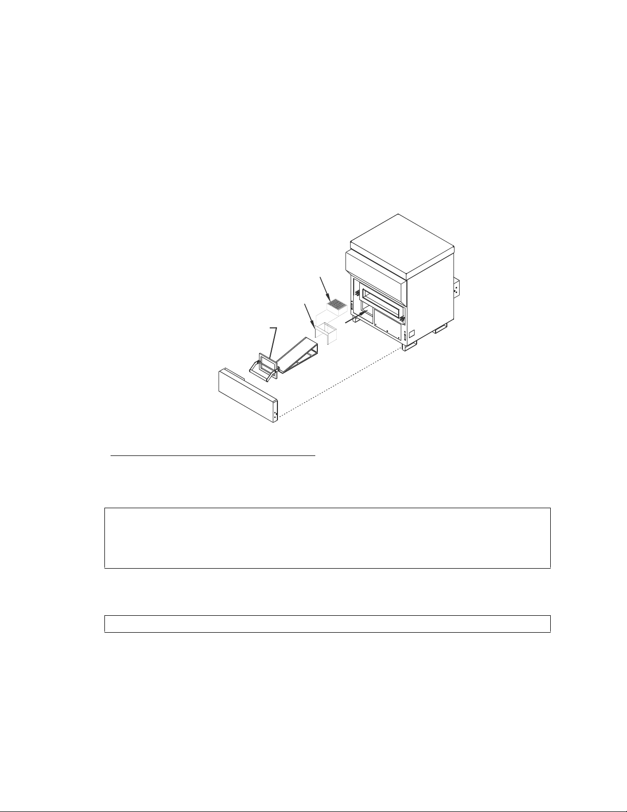
STEP 3: Grease Filter
PANEL
(GREASE FILTER)
1. Remove the lower access panel.
2. Remove the filter door. Spray the filter door with a non-caustic non-lye oven
cleaner.
3. Remove the filter assembly from the housing.
4. Tap the filter assembly gently, on the side of the trash can to remove loose
carbon particles. You may run the filter assembly through the dishwasher if
necessary. Set all of the filter parts aside.
CATALYTIC
CONVERTER
SUPPORT
FRAME
FILTER DOOR/GREASE FILTER
BOTTOM ACCE SS
ASSEMBLY
STEP 4: Cleaning the Cook Chamber
1. Spray non-caustic non-lye oven cleaner evenly and thoroughly into cooking
chamber and filter chamber. Be sure to cover inside walls, top, sides, etc. of
cooking chamber.
CAUTION: The wave-guide seal (located under ceramic wave-guide cap)
should be protected by the wave-guide cap during oven cleaning. Make
sure cap is in place while spraying cleaners into cooking chamber and
during the cleaning process.
2. Remove cook chamber door by releasing the latches at the rear of each side.
The door should be thoroughly cleaned with a non-lye oven cleaner.
CAUTION: Oven door is extremely heavy, use two people.
Page 26 of 87
Page 27
In the Morning
STEP 5: Cleaning the oven
1. Using damp cloth or green scrubby, thoroughly scrub the side and back walls,
as well as the top of the oven chamber. Use stiff blade scraper if needed (do
not use scraper on the wave-guide plug seal).
2. Once oven chamber has been cleaned, push debris through the opening
down into the filter chamber.
3. Wipe down interior of oven with damp cloth.
CAUTION: Remove all chemical residue to ensure food safety.
4. Remove ceramic wave-guide cap and wipe clean.
5. Clean filter chamber and pull debris into crumb tray. Empty crumb tray and
rinse with a damp cloth and wipe dry.
6. Use brush to loosen debris, or run through dish machine (do not soak). Allow
parts adequate time to dry.
7. Check grease collection pan (located on bottom of oven, below filter door)
and empty. Clean and replace.
STEP 6: Air Filter and Ventilation
1. Check bottom air filter (located next to grease collection pan on bottom of
oven). If dirty, soak in water with mild detergent.
2. Check circular vent located above bottom screen and clean vent screen as
needed.
3. Replace bottom air filter.
GREASE
COLLECTION
PAN
AIR FILTER
(FILTER CLEANING)
Page 27 of 87
Page 28

STEP 7: Reassemble oven
1. Replace door back into oven.
2. Caref ully replace filter door and lower access panel (oven will not start up if
filter door is not properly in place).
3. Replace cleaned ceramic cooking platter, chamber basket, wave-guide cap
and bottom air filter into oven.
4. Wipe down exterior of oven with a damp cloth and all-purpose cleaner.
Stainless steel polish may be used on the exterior only.
5. Reconnect oven at power supply.
6. Turn on oven at breaker switch.
7. Power on oven and observe Self-Test.
3.1.7 PERIODIC SIX-MONTH SCHEDULED CLEANING PROCEDURES
This procedure is recommended to lengthen the life of your TurboChef oven.
STEP 1: Cook Chamber Door
1. Release the latches on the rear slide rails of the cook chamber door
assembly.
2. Remove the cook chamber door.
CAUTION: Door assembly is extremely heavy (approximately 39.5 lbs.)
and awkwardly balanced. It is recommended that two people remove and
re-install the door assembly.
LATCH
RELEASE
(LTCHREL)
Page 28 of 87
Page 29

STEP 2: Slide Bearing Assemblies
1. Remove the socket head screws holding the four slide roller bearing
assemblies to the cook chamber side walls.
2. Clean the assemblies with hot water mild detergent.
3. Water rinse and dry.
4. Clean the oven side walls with hot water mild detergent. Take caution to
avoid excessive wetting or damage to the waveguide plug.
5. Water rinse and dry.
6. Reinstall four bearing assemblies.
WARNING: Be sure to reinstall the door stop brackets on the rear
assemblies for proper operation.
DOOR STOP
BRACKETS
(SLIDE)
Page 29 of 87
Page 30

STEP 3: Rear Access Panel
L
1. REMOVE the rear access panel from the oven to expose the rear slide
channel end caps.
REAR
ACCESS PANE
(BACKPNL)
STEP 4: Rear Slide Channel End Caps
1. REMOVE four screws holding each rear slide channel end cap
2. CLEAN inside the rails with hot water and mild detergent using a wire brush.
3. WATER rinse and dry.
4. REINSTALL the end caps.
REAR SLIDE CHANNEL
END CAPS
WITH HARDWARE
(CHCAPS)
Page 30 of 87
Page 31

CAUTION: DO NOT operate without end caps in place.
5. REINSTALL rear access panel.
Page 31 of 87
Page 32

STEP 5: Catalytic Converter
CAUTION: To prevent burns, only service the catalytic converter when the
oven is cool.
1. Remove the lower access panel by rotating installed handles up to expose
the grease filter area.
2. REMOVE the filter door and grease filter assembly by lifting up on the filter
door handle and removing the grease filter assembly.
3. REACH into the rear of the grease filter area and push the catalytic converter
up into the return airduct. Pull the support frame out while the catalytic
converter is raised. Remove the catalytic converter from the rear of the
grease filter area. CLEAN the catalytic converter support frame if necessary.
4. Inspect the catalytic converter for cleanliness. Look mainly for any blockages
caused by gummy organic particles. If there are no blockages, a simple rinse
with distilled water is sufficient and the catalytic converter can be reinstalled.
CAUTION: At no time should the catalytic converter be exposed to any
oven cleaners or degreasers, unless otherwise specified.
If there are blockages use the following procedure to dislodge them:
a) Shake catalytic converter to dislodge any large particles trapped in the
filter cells.
b) Mix a 6.5:1 solution of grease-off oven cleaner concentrate (6.5 parts) and
distilled water (1 part). Soak the catalytic converter in the solution for 30
minutes to 1 hour.
c) Soak/rinse the catalytic converter using distilled water for 10 minutes. This
process may be repeated if necessary.
CAUTION: Do not pound filter on counter tops or tap with any objects.
DO NOT use any type of abrasive materials to clean Catalytic converter.
CAUTION: Solutions containing phosphates, sodium, or other surfactants
must be avoided. Also it is very important, due to varying water qualities,
that the user only use distilled water during cleaning of this unit.
5. Reinstall the catalytic converter. Be certain that the catalytic converter and
support frame are properly positioned in the return air duct. Reinstall the
grease filter, filter door and lower access panel. Allow the oven to undergo a
warm-up cycle to dry the catalytic converter.
Page 32 of 87
Page 33

Catalytic Converter
Support Frame
Grease Filter Assembly
Filter Door
Grease Filter Area
STEP 6: Reinstall Door
1. REINSTALL the cook chamber door assembly.
CAUTION: Be sure the door rail catches are caught and door stops
operate correctly
(Cat Conv)
3.2 MAINTENANCE MODE TROUBLESHOOTING
Only authorized service personnel familiar with electrical repair and related
personal service considerations should attempt the following diagnostics and
repair.
Maintenance Mode Diagnostic Tests
Place the oven in MAINTenance mode for the following tests. (Press the MAINT
key, enter the appropriate Access Code and press ENTER). Take the following
readings and record the data:
1. Cooking chamber temperature recorded after oven is warmed up and
stabilized in Heat Maintenance Cycle. (CC °F) ___________
The cooking chamber temperature, after the oven has completed its warm up
cycle, should be within 20°F of Cook Point Setting (typically 540°F).
2. Heat exchanger temperature recorded after oven is warmed up and
stabilized. (HX °F) ___________
Page 33 of 87
Page 34

If the IAF setting is 0%, the HX temperature should be approximately 60°F
above the Cook Set Point temperature after the oven is properly warmed up.
If the IAF is greater than 0%, the HX temperature will be much closer to the
Cook Set Point temperature.
If the temperature is LOW, go to 5 (Heat Exchanger).
If the temperature is HIGH, go to 3 (Blower).
3. Blower (press BLR). The blower condition changes when the BLR key is
pressed. LED 7 will turn on to indicate the blower is on. ______ON
______OFF
If the blower does not come on proceed with the following steps. After each
step, press the BLR key and then STOP once the blower comes on.
a) Reset the blower motor drive by turning the oven off, wait 30 seconds
minimum, then turn the oven on.
b) Check AUX1 (AUX2) fuse(s). If a fuse is found to be open, replace with a
fuse identical in type and rating. For additional reference see the
appropriate schematic for the oven mode.
c) Check the connectors to the printed circuit boards located in the electrical
control box behind the keypad panel to ensure proper mating.
4. Blower Speed (press %BLR key). With the blower in the On condition the
blower speed should increase in 10% increments up to 100%. ______YES
______NO
5. Heat Exchanger (press HTR key). LED’s 11 and 16 should come on when the
key is pressed. _____YES ______NO
a) IF neither LED comes on, the heat exchanger may be over the maximum
temperature (700°F).
b) IF LED 16 does not come on, check HTR1 and HTR2 fuses and replace if
necessary with the same type and rating.
c) If the fuses are good, the over temperature thermostat, OT1, may by
tripped.
6. Mag1 and 2 (press M12 key). LEDs 14 and 15 should come on when the key
is pressed and held. ______ON ______OFF
If LED 14 or 15 do not come on, verify status LEDs 1, 2, 3, 4, 5 and 6 are on
with the cook door and filter door closed.
a) If status LEDs are all on, check and replace magnetron fuses as
required.
b) If status LED’s are not all on, determine which LED’s are not on and
check the appropriate interlock and monitor switches for proper contact
and alignment.
Page 34 of 87
Page 35

7. Magnetron Power Verification:
CAUTION: Use care in disposing of hot water.
Check the combined magnetron power by placing a shallow microwave safe
dish with 1000ml or 33.8 oz of cold water (approximately 40°F) in the oven.
Measure the initial water temperature. Using MAINTenance mode and M12
key, turn both magnetrons on for 60 seconds. Measure the final water
temperature. The water temperature rise should be a minimum of 45°F
(25°C).
3.3 SELF TEST AND ON-LINE ERROR MESSAGES
3.3.1 SELF TEST - Defective Messages
Refer to 3.3 Self Test Flow Chart to determine logic tests performed.
Note: When a “… Defective” Message is encountered, the operator may press
any key to continue the self-test. The software will track this fault for future
verification.
Displayed Message Go To
1. “BMSC DEFECTIVE” 4.3
2. “HX Heat Thermo OPEN” 4.7
3. “HX Heat °F RISE LOW” 4.7
4. “CC Heat Thermo OPEN” 4.7
5. “CC Heat °F RISE LOW” 4.7
6. “Mag 1/ (2) CURRENT LOW” 5.4
7. “Mag 1/(2) RF FLUC LOW” 5.4
8. “Mag 1/ (2) THERMO SW” 5.4
9. “Oven Door Open” 6.2
10. “Filter Door Open” 7.0
11. “Keypad DEFECTIVE” 8.3
Page 35 of 87
Page 36

3.3.2 ON LINE (while cooking) - Diagnostic Messages
Refer to 3.4 On-Line Flow Chart to determine logic tests performed.
Note: Only “Cook Temp Too Low” and “BMSC DEFECTIVE” cause a cook cycle
to terminate. Magnetron failures as well as cook temperature variances cause
cook cycle time extensions (shortening) to compensate for lost (increased)
available cooking energy. Each time another cook cycle is started, the faults are
reset and retested.
Displayed Message Go To
1. “BMSC DEFECTlVE” 4.3
2. “COOK TEMP TOO LOW” 4.7
3. “EC Temp ___ °F” 8.2
4. “Mag CURRENT LOW” 5.4
5. “Mag RF FLUC LOW” 5.4
6. “Mag THERMO SW” 5.4
Page 36 of 87
Page 37

3.4 SELF TEST FLOW CHART
Turn
on oven
power
1 sec later
In
Cool Down
state?
No
Is
Filter Door
secure?
Yes
Is
Oven Door
secure?
Yes
Energize MAG
Filaments
Is
MAG 1
Over Temp
OK?
Yes
Energize
MAG 1 and 2
Yes
COOLING DOWN
No
Alarm and Display
FILTER DOOR OPEN
No
Alarm and Display
OVEN DOOR OPEN
No
MAG 1 THERMOSW
Display
Cool
Down
Display
After 3
sec is MAG 1
current
?
Yes
After 6
sec RF pwrd
stirrer
?
No
After
12 sec into
test
No
Was Test
MAG 1
?
Yes
Replace MAG 1
with MAG 2
No
Display
MAG 1 CURRENT LOW
Yes
Display
MAG 1 TEST OK
Yes
Display
MAG 1 RF FLUC LOW
No
Press any key
to continue
Go to
A
(Flow 1)
Page 37 of 87
Page 38

(Flow 2)
Equals
240
Page 38 of 87
Page 39

3.5 ON-LINE FLOW CHART
No
Is
Blower ON
No
For Current
Event
?
Is
No
TW ON
For Current
Event
?
Yes
No
Yes
Is
Is
TW = 50%
TW = 50%
?
?
No
No
Yes
Are
Both MAGS
Drawing
Current
?
Either
Magnetron
Drawing
Current
?
Yes
Yes
P/O
COOK
After
5 sec Cook
With Blr On Is
Temp 85 Deg
Below Set
Point
?
Yes
Blower
Running
No
Is
RF Delta
OK and NO
Prior Low
Fluc
Yes
Yes
Is
?
No
Is
13 Seconds
Into Event
?
Yes
Queue Message
"MAG RF FLUC LOW"
Keep MAGs on
(Do not pulse)
Stop Cook, Display
COOK TEMP TOO LOW
Stop Cook, Display
BMSC DEFECTIVE
NoYes
Reset Fault
MAG CURRENT LOW
Increment Fault Counter
COOK TEMP TOO LOW
Increment Fault Counter
BMSC DEFECTIVE
Increment Fault Counter
"MAG RF FLUC LOW"
Go to
SELECT
RECIPE
Yes
No
Already
Mag Current Lo
or
Thermo Sw Fault
?
Is
Mag Thermo Sw
and NO Previous
Mag Thermo
Sw?
No
Is
TW = 50%
Yes
Yes
?
No
Queue Message
MAG THERMO SW
Queue Message
MAG CURRENT LOW
Have
5 seconds
Yes
past?
No
Increment Fault Counter
MAG THERMO SW
Increment Fault Counter
MAG CURRENT LOW
Are
Yes
MAGS
on?
No
Turn off
Turn on
MAGS
MAGS
CONTINUE
COOK
(Flow 3)
Page 39 of 87
Page 40

SECTION 4 - CONVECTION SYSTEM
4.1 BLOWER MOTOR ASSEMBLY
1. BLOWER WHEEL TIPS FACE AWAY FROM MOTOR (AS SHOWN)
2. LABEL ORIENTATION IS TO BE LEFT TO RIGHT AS FACING MOTOR. LOCATE IN AREA SHOWN,
KEEPING LEFT EDGE PARALLEL TO MOTOR FLANGE.
4 PL
(0.150 .020)+
3
4
2
134 PL
14
21
222 PL
23
DETA IL A
SCALE: 2/1
26 2 PL
27
2 PL
2 PL
28
24
8
25
(4.00)
10 4 PL
4
SEE DETAIL A
7 4 PL
1
6
BLOWER MOTOR ASSEMBLY - DWG 700-0310
ITEM PART NO. DESCRIPTION
1 T7000304 MOTOR MOUNTING PLATE
2 T7000306-2 HUB, FAN, SMALL
- T0048 BLADE RING
3 T7000307-1 BLADE, FAN
4 T7000308 BLOWER RING
5 T7000311 BLOWER CAP
6 T102708 HEAT SLINGER
7 T7000314 STANDOFF, MOTOR
8 T7000284 SHIM, SHAFT SEAL
- T0052 MOTOR MOUNT FANGE, NUTS AND BOLTS
9 T102732 MOTOR, FLANGE MOUNT, 1 HP, 7050 RPM
10 T101391 1/4-20 X .75 LG. SCREW, PFH, SS
11 T101830 3/8-16 X .75 LG. SCREW, SOCKET HD. CAP, SS
12 T101751 1/4-20 X .75 LG. SCREW, SOCKET HD. CAP, SS
13 T101746 8-32 X .38 LG. SCREW, SOCKET HD BUTTON, SS
14 T102320 # 8 WASHER, LOCK, INTERNAL TOOTH, SS
15 T100791 #242 LOCTITE THREADLOCKER
16 T7001154 LABEL, EXPOSED FAN DANGER
17 T102410 # 3/8 WASHER, LOCK, SPLIT, SS
19 T102400 # 1/4 WASHER, LOCK, SPLIT, SS
21 T100730 KEY, WOODRUFF, SS
22 T101715 8-32 X .25 LG. SET SCREW, SOCKET HD, SS
23 T7001177 GRAPHITE BLOCK, BEARING SEAL
24 T101733 SPRING, COMPRESSION, SS
25 T7001179 CLAMP, BEARING SPRING
26 T101005 10-32 NUT, LOCK, CRES
27 T102140 # 10 FLAT WASHER
28 T102350 #10 SPLIT LOCK
17 4 PL
11
9
1
12 4 PL
19
4 PL
4 PL
16
2
(Blower Motor)
Page 40 of 87
Page 41

4.2 BLOWER MOTOR CONTROLLER TESTS
The blower motor operates during the normal idle operation (the speed is set by
IAF in Maintenance mode for stabilization of the oven temperatures), while in the
cooking mode at the desired speed, and during the MAINTenance mode. The
MAINTenance mode allows the service technician to manually operate the
blower on and off and to change the speed.
Note: The Blower Shaft rotates in the clockwise direction when viewed
from front of oven.
4.3 BLOWER DEFECTIVE MESSAGES
The TurboChef oven will display a defective (fail) message, “BMSC
DEFECTIVE”, if the RUN status from the Blower Motor Speed Controller is
absent during self-test or while cooking.
In either case, they can be caused by the following problems:
SELF TEST WHILE
COOKING
BMSC
DEFECTIVE
BMSC
DEFECTIVE
CAUSE CORRECTIVE ACTION
Blower Motor Speed
Controller not returning the
“Running” status. (See
indicator LED 7)
1. Check BMSC Temperature. If
below 0°C, let controller warm
up and try again
2. Check Blower Fuses (See 8.0)
3. Check Air Filter for cleanliness.
4. Check Cooling Fan operation.
5. Check for proper operation of
interlock/monitor switches.
6. Check fault message on BMSC.
(See 4.4.2 or Reliance Electric
Manual.)
7. Check BMSC Settings. (See
4.5.2.)
8. Check all connections in the
blower circuit (Ribbon cables,
all blue wire signal circuits).
9. Replace BMSC. (See 8.0)
10. Replace I/O CCA. (See 8.0.)
11. Replace Blower Motor
Assembly. (See 4.1.)
12. Replace Controller CCA. (See
8.3.)
Page 41 of 87
Page 42

4.4 BLOWER MOTOR CONTROLLER DEFECTIVE MESSAGES
4.4.1 Fault Codes
The SP500 controller requires only minor troubleshooting. If a fault occurs, the
controller displays fault (ERR) codes to assist in troubleshooting. If a fault
condition occurs while the drive is running, (LED 7 on), the drive coasts to rest
and a 2-digit fault code is flashed on the display.
The fault code is also entered into the error log. The error log is designated as
“ERR” on the display.
4.4.2 How to Access and Read the Error Log
Multiple fault codes are entered into the error log in sequential order. The first
error to occur flashes on the display and two more errors may be logged into the
error log. (The error log must be accessed to see them). After three faults have
occurred, no more subsequent faults will be entered into the error log.
The faults entered into the error log are numbered sequentially. If first an
overcurrent fault were to occur, it would be in the error log as "1=OC". If next a
thermal overload fault were to occur (and the first error was not yet cleared), it
would be in the error log as "2-OL", and so on.
The last fault to occur will appear first when accessing the error log. For
example, if the last fault was a low bus fault, and the error log has 3 entries, then
the error log would display "3-LU" when the error log is first accessed.
Faults are retentive to the error log if a power loss occurs. The entire error log
can be cleared by pressing the STOP/RESET button.
To access the error log:
1. Press the MODE/ENTER
key until the Program LED
lights.
2. Press the down arrow key
until “ERR” is displayed.
The error log precedes
parameter F-00 and follows
F-49.
RPM RUN
% Load Program
Volts Forward
Remote Reverse
RPM RUN
% Load Program
Volts Forward
Remote Reverse
Mode
Enter
START
Mode
Enter
START
Forward
Reverse
STOP
RESET
(Error 1)
Forward
Reverse
STOP
RESET
(Error 2)
Page 42 of 87
Page 43

3. Press the MODE/ENTER
key to access the error log.
4. Press the up arrow key to
move through the error
codes.
5. Press the STOP/RESET
key to clear the error log.
Refer to 4.4.3.
6. The display returns to the
active monitor display.
RPM RUN
% Load Program
Volts Forward
Remote Reverse
RPM RUN
% Load Program
Volts Forward
Remote Reverse
RPM RUN
% Load Program
Volts Forward
Remote Reverse
Mode
Enter
START
Mode
Enter
START
Mode
Enter
START
Forward
Reverse
STOP
RESET
(Error 3)
Forward
Reverse
STOP
RESET
(Error 4)
Forward
Reverse
STOP
RESET
4.4.3 Messages in Error Log
OH: Thermostat / Drive Overload
Cause Action
The internal thermostat has caused a trip that indicates
excessive temperatures in the controller.
1. The ambient temperature of the controller is
exceeded.
Press the STOP/RESET button (or cycle oven power off for 30
seconds, then on.) The error will not clear until the internal drive
temperature is back withi n range. This may take a few seconds.
1. Check Blower shaft to see if it freely turns.
2. Check t he Oven Air Fi lter and veri fy the Floor Fan is operat ing (If
(Error 5)
the oven is hot). Refer to the bl ower motor/controller test.
Page 43 of 87
Page 44

OC: Overcurrent
Cause Action
The current rating of the controller (>200% rated drive
current) had been exceeded.
This fault can be caused by any of the following conditions:
1. S hort i n drive outputs 1. V erify that the input and output wiring to the drive are properly
2. Ground fault condition 2. Verify that the output wiring to the motor is not connected to
3. Instantaneous overcurrent resulti ng in greater than
200% rated drive current.
FL: Function Loss
Cause Action
The remote (external) function loss signal has been
asserted. (Terminals 10 and 11.)
1. The external equipm ent connected to the function
loss terminals has failed, or is giving repeated stop
requests.
HU: High bus voltage conditi ons
Cause Action
The D-C bus charged above the IET threshold level of
430 volts.
1. Power Line voltage transient has caused the overvoltage condition to occur.
2. Deceleration rate to fast (Function 2). 3. Check the decel rate (Function 2), and compare with chart on
LU: Low bus voltage conditions
Cause Action
The D-C bus has fallen below the IET low threshold
level of 180 volts.
1. Momentary loss of input power.
2. Low line voltage on i ncoming power.
Note: If a line dip or mom entary power loss occurs and t he bus level is able to rise back t o the proper range withi n 500 ms., the
drive will automatically restart (if the drive was already running when the fault occurred.) If t he drive does not res tart , perform above
steps, or cycle oven power off for 30 seconds, then on.
OL: Electronic thermal overload
Cause Action
The electronic thermal overload trip level has been
exceeded. This fault protects the drive and motor from
overheating due to excessive current within a specified
period.
1. The Current Limit Setting (Function 5) is not set
correctly.
2. Function 14, Elec tronic Thermal Overl oad is not s et
correctly to match the motor and controller
combination.
3. Motor Shaf t is bound up or hard to turn.
Any of the following codes indic ate a SP500 motor controller failure.
Codes Action
AdPF, CH, diSc, E Erd, EEOU, EPCH, FSF, In00, In02,
In04, In06, In08, In10, In15, noAd, OLP2, rSF, rEF1,
rEF2, SELU, UnOP, 7rAP, r1, r2
Press the STOP/RESET button (or cycle oven power off for 30
seconds, then on).
connected
Ground or any other voltage source.
3. Check motor to insure shaft is free to turn.
Press the STOP/RESET button (or cycle oven power off for 30
seconds, then on.) This fault will not clear until t he func tion los s si gnal
is unasserted.
1. Check the external equipment wired to the remote function l oss
terminals (10 and 11.)
2. Check function loss connections.
Press the STOP/RESET button (or cycle oven power off for 30
seconds, then on.) The error will not clear until the bus falls below the
high bus level.
1. If occurrence seldom, possible no problem.
2. If occurrence is high, suspect incoming power problem or
incorrect setting of the SP500 controller (Replace).
4.5.2.
Press the STOP/RESET button (or cycle oven power off for 30
seconds, then on.) The error will not clear until the input line voltage is
within the proper range. This may tak e a few seconds.
1. Check incoming power.
2. Check incoming power.
Press the STOP/RESET button (or cycle oven power off for 30
seconds, then on.) The error will not clear until the drive has
integrated to the proper range. This may take a few seconds.
1. Verify the value of Function 5.
2. Verify the value of Function 14.
3. Check motor to insure shaft is free to turn.
1. Replac e t he SP500 controller.
Page 44 of 87
Page 45

4.5 BLOWER OPERATION
4.5.1 How to turn Blower On
1. Set the master switch to ON position.
2. Press MAINTenance key. (Refer to Control Panel Layout, Section 2.4), enter
access code, then press ENTER.
3. Press the (BLR) key if LED 7 is off. Press (% BLR) and verify the blower
speed increases in 10% increments until 100% blower speed (7050 RPM
indicated on BMSC) is achieved. Verify LED 7 (BM) illuminates on the
keypad.
4. Verify that the blower motor rotates freely and does not vibrate from
imbalance.
5. Verify that the blower shaft rotates in the clockwise direction when viewing
the shaft from the front of the oven.
6. Press (BLR) key to stop the blower motor.
4.5.2 Blower Motor Speed Controller Settings
The following is included for setting up a new Motor Speed Controller or if
previous settings have changed.
To Access the Controller Setup:
1. W ith oven Master switch ON, select "MAINTenance" key and enter access
code.
2. Press the MODE/ENTER key on the Controller to select PROGRAM mode.
The Controller PROGRAM Led will be illuminated and the display will show
"F-00".
3. Move the up/down arrow keys until the desired function number is displayed.
4. Press the MODE/ENTER key to display the value.
5. Verify the Blower Motor Speed Controller settings by referring to the
Controller Nameplate to choose the correct settings from the following chart.
6. Press the up/down arrow keys to change the value, if desired.
7. Proceed to the next function to be verified by pressing the MODE/ENTER
key.
8. Press the STOP/RESET key to exit the PROGRAM mode.
Page 45 of 87
Page 46

BLOWER MOTOR SPEED CONTROLLER SETTINGS
Function D2-3356 Function D2-3356 Function D2-3356
F-00 1 F-11 100 F-22 0
F-01 2.0 F-12 0 F-23 20
F-02 5.0 F-13 OFF F-24 20
F-03 3.0 F-14 100 F-25 20
F-04 120 F-15 ON F-26 10
F-05 100 F-16 OFF F-27 1
F-06 0 F-17 ON F-28 230 **
F-07 120 F-18 OFF F-29 SPd
F-08 7050 F-19 OFF F-49 3.10 *
F-09 0 F-20 OFF ***
F-10 8 F-21 5
* Read only setting. ** Factory set. Do not change. *** PW=257 (Password)
4.6 BLOWER WHEEL REPLACEMENT
If the blower wheel is removed from the motor shaft for any reason it must be
replaced with the .150 ± .020 spacing shown.
1. Set the motor on end. Use two 5/32 (.156) x 4” long square key stock as
spacers. The final spacing must measure between .130” and .170” after
tightening.
Page 46 of 87
Page 47

4.7 HEAT EXCHANGER
g
No More Than 3 Inch of Tubing
The Heater core consists of 18 tubular heating elements, which are divided into
sections depending on the model or configuration of the oven. Each individual
heating element is rated 450 watts @ 240 VAC. Power input terminals H2 and
H3 (Buss bars) are in series with the oven Over-temperature Thermostatic
Switch, OT1. The Over-temperature Switch senses the rear exterior surface of
the Heat Exchanger and opens when the rear surface of the Heat Exchanger
exceeds 600°F (315°C), limiting the maximum fault temperature of the heat
exchanger. (This corresponds to a Heat Exchanger temperature of
approximately 720°F (382°C)). Two Thermocouples are used for oven
temperature control, one measures the Heat Exchanger Core Temperature, HX,
and the other measures the Air Temperature entering the Cook Chamber, CC.
The Heat Exchanger is used to:
1. Store energy (heat).
2. Provide thermal uniformity (within the oven).
3. Provide rapid heating of the convection (cooking mode) air.
How to Manually Turn Heaters On:
1. Turn oven on.
2. Press MAINTenance key (MAINT).
3. Enter access code.
4. Press ENTER key.
5. Press the HTR key to alternately turn the heater elements on and off.
Note: LED’s 11 and 16 will come on when the heater elements are on.
CAUTION: DO NOT leave the heaters on for long periods, as the oven will
rapidly heat to maximum allowed temperature (approximately 720°F
(382qC)).
REAR VIEW OF OVEN
OTI Capillary
Should Be Under Insulation
HX Thermocouple
Thermocouple Fittin
(100550)
Electronic
Compartment
3.50 (88.9)
(102065)
2.50
(63.5)
CC Thermocouple
(102065)
(Heat Exch 1)
Page 47 of 87
Page 48

10
(20X)
1
(20X)
3
1
9
(20X)
(20X)
2
4
2
11
13
BUSS BAR
1
12
TOP COVER
12
2
6
7
8
REAR
HEAT EXCHANGER COVER, BUSS BARS AND CORE ASSEMBLY
ITEM PART NO. DESCRIPTION
1 T100960 NUT, HEX, SS, 10-32
2 T102140 WASHER, FLAT, SS, # 10
3 T102350 WASHER, LOCK, SPLIT, SS # 10
4 T102130 WASHER, FLAT, SS, # 10 X 1” O.D.
5 T7000449 GASKET, RF, COVER-HEAT EXCHANGER
6 T7000454-4 BUSS BAR, INPUT
7 T7000455-4 BUSS BAR, INPUT,
8 T7000456-4 BUSS BAR, INPUT, FRONT
9 T102260 WASHER, LOCK, EXT. TOOTH, SS #10
10 T100802 LUG, RING, 10 GA #8, HI-TEMP
11 T100150 BUSHING, CUP, 2C0504
12 T102120 WASHER, CRANGLAS 6X0004
13 T100160 BUSHING, SHOULDER 2C050
(Heat Exch 2)
Page 48 of 87
Page 49

4.8 CERAMIC INSULATOR REPLACEMENT
1. Disconnect the oven from the power source.
2. Remove the insulation from the top of the heat exchanger exposing 24 #1032 nuts.
3. Apply a high pressure lubricant to the studs and nuts before attempting
removal to keep galling from occurring and studs twisting off.
CAUTION: Use care to ensure that studs are not twisted off. Do not drop
anything into the heat exchanger. If hardware is dropped into the heat
exchanger, it MUST be removed by fishing from the top or remove the HX
and retrieve part and/or broken ceramic pieces.
4. Remove the top baffle weldment by carefully prying under the front lip with a
large screwdriver.
CAUTION: Do not damage the RF gasket.
5. Check the insulators at the heater terminals. If they are cracked or broken,
replace with new insulators. Tighten the insulator nuts to 6.3 inlb.
CAUTION: If the ceramic insulator is broken, be sure to find all the
ceramic pieces so that they do not end up on someone’s food.
6. Reinstall the heat exchanger top baffle with the wide opening facing front.
Reinstall the 24 10-32 nuts, and the oven insulation. Retape the insulation
seams.
Ceramic insulator breakage is typically caused by one of two problems.
• Excessive tightening of the insulator assembly. This puts excessive
compressive stress on the ceramic insulators.
• Excessive stiffness of the bus bars. This puts high stress on the ceramic
insulators when the heat exchanger is bounced around, such as in shipping.
Page 49 of 87
Page 50

4.9 HEAT EXCHANGER DEFECTIVE MESSAGES
SELF TEST WHILE COOKING CAUSE CORRECTIVE ACTION
HX Heat Thermo
OPEN
HX Heat RISE
LOW
NOTE:
CC Heat Thermo
OPEN
CC Heat RISE
LOW
Heaters must be
on to check
Currents. See 4.6
to turn-on heaters.
COOK
TEMPERATURE
TOO LOW
HX Thermocouple
amplifier indicates open,
(999°).
HX Temperature failed to
rise 21°F(11.7°C) in 4
minutes
CC Thermocouple
amplifier indicates open
CC Temperature failed to
rise 14°F(7.8°C) in 2
minutes after HX test
passed with 75% Blower
on
CC Temperature 84°F
(47°C) or more below
cook set point after 5
seconds or more into
cook cycle
See Thermocouple troubleshooting below.
1. Check heater fuses. (See
8.1), If fuses are blown,
check for short to chassis
on H1, H2, H3.
2. Check input current to Heat
Exchanger. There should be
no more than 1 amp
difference between readings
for each of the 3 phases
(See Schematic for rated
current).
3. Check operation of the
heater relay. (See 8.1)
4. Check voltage across oven
Over-Temp. Thermostat,
OT1. (See 8.1)
5. Check blower operation
(See 4.0-4.5)
6. Check Cook Temp Set
Point. (See 2.4.2)
7. Check crimp connections.
8. Replace HX Thermocouple.
(See 4.7)
9. Check crimp connections.
10. Replace CC Thermocouple
(See 4.7)
11. Check heater fuses. (See
8.1)
12. Check blower operation
(See 4.4)
13. Check CC Thermocouple
14. Check blower operation.
(See 4.4)
15. Check CC Thermocouple
circuitry.
Thermocouple Troubleshooting:
1. Display Reading 77°(25qC) (Room Temperature)
Acceptable condition from a cold start.
2. Display Reading 999°(999qC)
Indicates related thermocouple is open. Check thermocouple connections.
Page 50 of 87
Page 51

SECTION 5 - MICROWAVE SYSTEM
5.1 MEASURING MICROWAVE RADIATION LEAKAGE
The following RF emissions test must be performed every time a service call is
done on a TurboChef oven. Report your findings on the work order.
This test must be done in conformance with 21 CFR, Ch1, Part 1030Performance Standard for microwave and radio frequency emitting products.
Part 1030.10 Microwave Ovens. (C) Requirements - (1) Power Density Limit.
“The equivalent plane wave power density existing in the proximity of the
external oven surface shall not exceed 1 milliwatt per square centimeter at any
point 5 centimeter or more from the external surface of the oven, measured prior
to acquisition by purchaser, and, thereafter, 5 milliwatt per square centimeter at
any point.”
The following areas are to be measured when performing a RF test.
• Cook Door.
• Filter Door.
• At any point on the outside of the oven fully assembled. (With all covers).
Note: Do not operate the magnetron without a load such as 275 ml of water in
the cooking chamber. The tip of the survey meter spacer cone should be
touching the oven surface being measured, with the probe handle perpendicular
to the surface. Move the cone at a speed of less than 0.5 inch per second.
IN CASE THE OVEN FAILS
RADIATION LEAKAGE TEST:
WARNING: If the oven fails radiation
test , the oven must be taken out of
service immediately until the defect
is corrected. In addition, the leakage
reading and corrective action must
be reported on the work order w hen
the defect is corrected and oven
placed back in service. If further
information is required for this test,
please call the TurboChef, Inc.
Customer Service Toll Free Number
listed on the front of this manual.
(micro check)
Page 51 of 87
Page 52

5.2 HOW TO TURN MAGNETRONS ON/OFF FOR TESTING
The magnetrons may be turned on/off for testing using the MAINTenance mode.
The magnetrons will remain on in this mode as long as the appropriate key is
depressed.
Caution: Do not operate the magnetrons for more than 5 seconds without a
load in the cooking chamber. A suitable microwave load is 275 ml (9.3 oz)
of cold water.
With the oven in the normal “ON” state:
1. Press MAINTenance key.
2. Enter access code.
3. Press ENTER.
4. Press and hold (M12) key. Verify LED 14 (M1) & LED15 (M2) illuminate on
the oven keypad LED display.
5. Press the STOP key to return to the normal mode from the maintenance
mode.
Note: When energizing the magnetrons, check for fluctuation of RF power
on the oven display due to the stirrer blade motion causing the microwave
energy to move around in the cooking chamber. The RF power indication
should be varying significantly during operation. The RF indication is
sampled for 10 seconds. If the difference between the maximum sample
and minimum sample is less than 20 units during self-test or 10 units
during cooking, the error message “RF FLUC LOW” will be displayed.
Page 52 of 87
Page 53

5.3 MICROWAVE COMPONENT LOCATIONS
ITEM PART NO. DESCRIPTION
1 T7001344 INSTALLATION ASSEMBLY WAVEGUIDE SEAL
1A T7001336 ASSY WAVEGUIDE CLAMP
1B T7001333 SEAL, PLUG, TEFLON
1C T7001213 PLUG WAVEGUIDE QUARTZ
1D T102650 WAVE SPRING WASHER 9”
1E T7001321 SEAL, RING, WAVEGUIDE
2 T4000240-2 BLADE STIR MOTOR
3 T102270 WASHER, STAR, CRES #6
4 T101590 SCREW, PPH, SS, #6-32X.38 LG
5 T102380 WASHER, SPLIT, LOCK #6
6 T100860 MAGNETRON (HITACHI 2M121A)
7 T100690 INSULATOR KLIXON
8 T102070 THERMOSTAT, KLIXON
9 T101683 SCREW, PPH, TYPE F#5X.25 LG
10 T7001284-1 ASSY STIRRER MOTOR
10A T7001290 SHAFT, STIR MOTOR
10B T7001285 ASSY, STIR MOTOR PLATE
10C T100891 MOTOR, SYNCHRONOUS, 6.0/7.2 RPM
10D T102300 WASHER, INT. TOOTH LOCK #4
10E T101520 SCREW, PPH, 4-40X.25 LG
10F T102716 CONNECTOR, PLUG
10G T102035 PIN, CRIMP, MALE
11 T102360 WASHER, SPLIT, LOCK #2
12 T101490 SCREW, PPH, SS, 2-56X.18 LG
13 T2656148-7 CONNECTOR, RECEPTACLE
14 T7000408-3 ASSY, RF CABLE, RG405
15 T7001226-4 TUBE, SHIELD (MAG 1)
16 T7001226-3 TUBE, SHIELD (MAG 2)
17 T102350 WASHER, SPLIT, LOCK #10
18 T102140 WASHER, FLAT, #10
19 T1799 SCREW, COMMON TYPE ZINC PLATED #10
20 TDB FLANGE NUT, METRIC, M5
Page 53 of 87
Page 54

1E
11
12
14
1
MICROWAVE CHAMBER
(2X)
1C
1B
1A
4
3
4
5(2X)
3(2X)
2
7
3
8
9
5
OR
13
DETAIL A
6
SEE DETAIL A
15
16
10
(2X)
(2X)
10A
10D
10E
10B
10C
171819
Magnetron Side View
10F
10G
(Micro Comp)
Page 54 of 87
Page 55

5.4 MICROWAVE ERROR MESSAGES
SELF TEST WHILE COOKING CAUSE CORRECTIVE ACTION
Mag 1(2)
CURRENT LOW
Mag 1 RF FLUC
LOW
Mag 1(2) THERMOSWMag THERMOSWDetected MAG1 or
Mag CURRENT
LOW
Mag RF FLUC
LOW
Note: Stirrer
motor operates
only when
magnetron
filaments are are
ON.
Remove
magnetron fuses
when inspecting
stirrer motor
operation.
Did not detect current to
the magnetron transformer 1(2).
If magnetrons are ON at
least 15 sec. During
cook, RF power has
failed to fluctuate 10 in
10 sec.
MAG2 thermal switch,
(KLXM1, KLXM2) open.
Implying the magnetron
case temperature is
above 212°F (100°C).
1. Check magnetron fuses.
(See 8.1). If fuse(s) are
blown, check Monitor relay
and interlock switch
operation (LEDs 1-6).
2. Check Mag and Filament
relay operation.
3. Check Magnetron,
magnetron transformer,
filament transformer
capacitor, and diode. (See
5.5-5.10)
Note: If a magnetron is found to
be defective, the failure may be
due to moisture and/or other
contaminants in the waveguide
cavity which causing the
magnetron to overheat due to
high reflected power. If moisture
is found in the waveguide cavity,
the cavity must be cleaned and
resealed.
See 5.11 for additional
information.
1. Check RF power detection
cable. (See 5.3)
2. Check RF sensor. (See
5.11)
3. Check operation of the
stirrer motor Check for any
loose wires in the circuit.
4. Check attachment of stirrer
blade.
5. Check for loose wires.
6. Change I/O CCA. (See 8.1)
7. Check for failed waveguide
seal.
1. Check MAG1, MAG2 over
temperature switch.
2. Check for loose wiring in the
circuit.
3. Check Air Filter to see if is
stopped up or dirty.
4. Check proper operation of
magnetron blower (Note:
Mag. fan operates only
when magnetrons are on.)
Page 55 of 87
Page 56

5.5 MAGNETRON
COOLING FINS
MAGNETRON CASE
ANODE SUPPLY TERMINAL
The magnetrons emit RF energy that is coupled to the cook chamber via the
waveguide assembly. The RF energy generated by the magnetron occurs at a
frequency of 2450 MHz.
Caution: Do not attempt to measure the magnetron voltages with a typical
voltmeter. (Voltages are approximately 4000-4500 VDC.)
ANTENNA
HIGH VOLTAGE
FILAMENT TERMINALS
(Magnetron)
How to check a magnetron for open or shorted filaments:
1. Disconnect the ac power source and discharge the High Voltage Capacitors.
2. Isolate the magnetron from the circuit by removing the wires from the F and
FA terminals.
3. An ohmmeter connected between the filament terminals (F, FA) should
indicate a reading of less than 1 Ohm.
4. A continuity check between either filament terminal and the magnetron
chassis should indicate an infinite resistance (open).
Page 56 of 87
Page 57

5.6 HIGH VOLTAGE (HV) MAGNETRON TRANSFORMERS
The high voltage magnetron (anode) transformer has a primary winding and two
secondary windings. The filament secondary of the anode transformer is not
used. The primary winding of the anode and filament transformers have 208/240
VAC applied from the line voltage circuit. The secondary filament transformer
winding (4.6 VRMS @ 14 Amps) is connected to the filament in the magnetron
(F, FA terminals) to supply magnetron filament power. The secondary HV Anode
winding (2250 VPK @ 0.83 Amps) is doubled (converted to -4500 VDC @ 0.415
Amps) by the HV diode and capacitor and connected to one side (FA terminal) of
the filament. The Magnetron Anode is grounded. The cathode in the magnetron
is the filament. The anode to (cathode and) filament is supplied by operating the
filaments at a negative potential of 4500 VDC.
To change or confirm frequency see Appendix B for Japanese HV
transformer.
To change or confirm voltage see Appendix D for filament transformer.
240VAC
PRIMARY
200/208VAC
PRIMARY
FILAMENT TRANSFORMER
4.6VAC SECONDARY
45
BACK VIEW
3
2
FRONT VIEW
1
240V
200/208V
208-240
VAC INPUT
PRIMARY
COMMON
HV ANODE WINDING (SECONDARY
T4 FILAMENT
TRANSFORMER
3
2
1
T3 OR T4
T1 OR T2
ANODE TRANSFORMER
2
1
T1 OR T2
4
5
3
NOT USED
4
1.05uF (60Hz)
1.2uF (50hZ)
50Hz
7
6
60Hz
CAPACITOR
5
HV
15KV
HV DIODE
ANODE TRANSFORMER
REAR VIEW
7
50Hz
60Hz
6
5
FA
F
MAG1 OR MAG 2
4500 VPK
415 MA
4
FILAMENT
WINDING
3
(SECONDARY)
2
208-240 VAC
(PRIMARY)
1
(Transformer)
Page 57 of 87
Page 58

TRANSFORMER SPECIFICATIONS
2X 0.250
.12
T1 or T2 Anode Transformers T3 or T4 Filament Transformers
Primary DCR 0.58 Ohm.
Secondary DCR: (5-6) 46.39 Ohm
(5-7) 54.00 Ohm
Input Voltage : 208-240 VAC, 50/60 HZ
Input Current: 9.0 Amps RMS
Anode Voltage: 4500 VDC Peak @
0.415 Amps
Primary DCR (1-2) 23.2 Ohm
(1-3) 27.8 Ohm
Secondary DCR: (4-5) .020 Ohm
Input Voltage : 208/240 + 10%
50/60 HZ
Input Current: 0.42 Amps @ 208 VAC
0.35 Amps @ 240 VAC
Filament Voltage: 4.6 VAC @ 14 Amps
How to check a transformer:
1. Disconnect the power source and discharge the capacitor.
2. Isolate the transformer from the circuit. (Wires are labeled but remember where they
go)
3. Check impedance of the primary and secondary windings. ( See above.)
4. Filament winding should read less than 0.1 ohms.
5. Reconnect wires.
5.7 HIGH VOLTAGE DIODE
The High Voltage Diode is an assembly constructed by connecting several 10001500 volt semiconductor diodes in series to increase the reverse voltage
capability. In the circuit, the high voltage diode conducts to prevent the filament
voltage from becoming positive, thus as the high voltage winding of the
transformer goes to 2250 VPK, the high voltage capacitor is charged to 2250
volts. When the high voltage winding starts to go toward negative, the High
Voltage Diode becomes non-conducting with the charged High Voltage
Capacitor in series with the High Voltage Winding. When the transformer gets to
its negative peak of -2250 VPK, the voltage applied to the filament is negative
4500 volts.
0.75
0.42
0.75
3.00
1.68
4X R FULL
0.32
0.16
0.31
1.22
0.25
HIGH VOLTAGE DIODE
*8FKQFG
Page 58 of 87
Page 59

How to check a diode:
Caution: Do not attempt to measure HV directly.
1. Disconnect the oven from the power source.
2. Isolate diode from circuit.
3. Connect the meter leads to the diode terminals.
4. Infinite resistance (open) should be indicated in the reverse direction.
5. Resistance readings in the forward direction may be indeterminate. *
6. If there is continuity in both directions (shorted diode).
Due to the HV diode consisting of approximately 15 X 1000 volt diodes in series
the forward diode drop is approximately 9 volts. A normal low voltage ohmmeter
will not provide sufficient voltage in the resistance ranges to measure an
impedance in the forward direction of the High Voltage Diode.
High Voltage Field Test Procedure
1. Locate the diode to test, make sure that the magnetron circuit is not powered
up.
2. Carefully remove the wire going to the capacitor from the diode - terminal.
CAUTION: The capacitor can maintain a charge for a long time.
3. Connect a 100 ohm, 10 watt resistor from the power diode (D5 Cathode) on
the I/O board (+24.0 volts) and the (-) lead of the diode.
4. Measure the voltage between the Diode (-) terminal and chassis ground (or
the other side of the high voltage diode) using a multimeter on the DC range.
a) If the voltmeter reads zero (less than .3 volts) the diode is shorted.
b) If the voltmeter reads greater than 15 volts the diode is open.
c) The following should be considered good diodes:
Voltmeter Reading Diode Part Number
6.6 to 7.8 volts HVP15
6.6 to 7.8 volts HVCA
8.2 to 9.8 volts GLC 32
Theory:
The 15,000 volt High Voltage Diode, 100480, is really an assembly of several
lower voltage diodes in series. Different manufacturers of the high voltage diode
assembly may make it up using different number of diodes. For instance, 10 x
1,500, 12 x 1,250 or 15 x 1000 volt diodes could be used to make up the high
voltage diode assembly.
Page 59 of 87
Page 60

The test above provides approximate 180 milliamps of current in the diode’s
(
)
forward direction and measures the voltage drop. Each diode in the assembly
should have approximately .55 to .65 volts drop under these conditions. By
measuring the voltage drop, the number of good diodes can be estimated to see
if any of the series diodes are shorted.
The following chart lists the typical voltage drop expected across the high voltage
diode when conducting 180 milliamps of current.
# Voltage Drop # Voltage Drop # Voltage Drop
1 .55 to .65 volts 7 3.8 to 4.6 volts 13 7.1 to 8.5 volts
2 3.8 to 1.3 8 4.4 to 5.2 14 7.7 to 9.1
3 1.1 to 2.0 9 4.9 to 5.9 15 8.2 to 9.8
4 1.6 to 2.6 10 5.5 to 6.5 16 8.8 to 10.4
5 2.2 to 3.3 11 6.0 to 7.2 17 9.3 to 11.1
6 2.7 to 3.9 12 6.6 to 7.8 18 9.9 to 11.7
100 Ohm 10W
24.0 VDC
5.8 HIGH VOLTAGE CAPACITOR
The High Voltage Capacitor is part of the voltage doubler which stores the
transformer peak voltage thus creating a voltage doubler to supply the
magnetron with a pulsed -4500 volt dc anode voltage. The capacitor is either
1.05 µF for 60 Hz power or 1.2 µF for 50 Hz power.
CAUTION: After removing the oven from power and prior to servicing the
oven, discharge the capacitor. Never assume the discharge resistor
internal to the capacitor has completely discharged the capacitor.
1.05uf 2500V 60Hz 70C
1.2uf2500V60Hz70C
AEROVOX N50H2510GR
AEROVOX N50H2512GR
OR
INTERRUPTERS
CAPACITOR
DISCHARGE
RESISTOR
C
1.05 .15
Elec Conn
INTERRUPTERS
µ
1.05 F CAPACITOR
DISCHARGE RESISTOR
.15 F CAPACITOR
µ
DISCHARGE RESISTOR
SINGLE 1.08 OR 1.20 F
(Early D3 Models)
µ
DUAL 1.05 OR .15 F
(Later D3 Models)
µ
(HV capacitor)
Page 60 of 87
Page 61

How to check a capacitor:
(Mag Over T em p Sw)
1. Disconnect the oven from the power source.
2. Isolate the capacitor from the circuit.
3. Fully discharge the capacitor.
4. Connect the ohmmeter between the capacitor terminals. The meter should
indicate a low impedance and then slowly return to infinite resistance.
5. Reverse the ohmmeter leads. Repeat step 4.
6. Check each terminal to case. Infinite resistance (open) should be indicated.
5.9 MICROWAVE MODE STIRRER
The microwave mode stirrer and associated stirrer blade changes the modal
pattern in the cook chamber to reduce hot spots of microwave energy from
occurring, thus providing more even cooking. The stirrer motor is a 240 VAC
synchronous motor that turns at 7.2 rpm (6 rpm in 50 Hz units).
MOTOR
6.0/7.2 RPM
STIR MOTOR WIRING DIAGRAM
RED
RED
1
2
240 VAC
50/60 Hz
5.10 MAGNETRON OVER-TEMPERATURE SWITCH
The Magnetron Over-temperature Switch is designed to protect the magnetron
from overheating. During normal operation, the switch is closed . The overtemperature switch opens when the magnetron case exceeds 212°F (100°C).
Overheating may occur due to a dirty or blocked Air Filter, a failed Magnetron
Cooling Fan or a contaminated waveguide cavity.
(Stirrer)
Page 61 of 87
Page 62

5.11 RF OUTPUT MONITOR CIRCUIT
A RF sensor in the microwave waveguide assembly detects a portion of the radio
frequency (2450 MHz) energy emitted during the operation of the magnetron(s).
A RF Cable Assembly connects the RF sensor to a SMA connector on the I/O
Circuit Card Assembly, CCA. On the I/O Circuit Card Assembly, the RF energy is
detected and amplified. The amplifier gain is controlled by R10 on the I/O CCA.
The analog signal is then routed via a flat cable to the Control CCA where it is
digitized by the microprocessor for control and display. Note: RF readings are
displayed in MAINTenance and Diagnostic displays. The readings, measured
over a 10 second period, must fluctuate a minimum of 20 units to pass self-test
and 10 units to pass the on-line tests (while cooking). The Mode Stirrer rotates at
7.2 rpm for 60Hz and 6 rpm for 50Hz.
How to check the RF Sensor
The RF Sensor is an electrostatic type.
1. Disconnect the RF coax cable from the I/O CCA board at the SMA connector.
2. The resistance between the center conductor and shield as measured at the
SMA connector should be infinite (open).
3. Any measured resistance indicates the RF sensor may be defective or may
require cleaning to remove any carbon deposits. Also disconnect the coax
cable from the RF sensor to check that each has infinite resistance between
the center connector and coax shield or probe body. Also check that the SMA
connector’s center pins are properly positioned in the connector. Replace or
clean the defective part.
5.12 MAGNETRON POWER VERIFICATION
CAUTION: Use care in disposing of hot water.
Check the combined magnetron power as follows:
1. Place a shallow microwave safe dish with 1000ml or 33.8 oz of cold water,
approximately 40°F (4°C) in the oven.
2. Measure and record the initial water temperature.
3. Using MAINTenance mode and the M12 key, turn both magnetrons on for 60
seconds.
4. Measure the final water temperature. The water temperature rise should be a
minimum of 450°F (25°C).
Page 62 of 87
Page 63

M/W PLUG SEAL
CCW INCREASE, CW DECREASE GAIN
(SHOWN REMOVED)
RF SIGNAL IS
DIGITIZED BY
PROCESSOR
AND DISPLAYED
FLAT CABLE CARRIES ANALOG
SIGNAL TO CONTROL CCA
R10 (OR R17) ADJUSTS GAIN,
MICROWAVE
WAVEGUIDE
ASSEMBLY
FRONT
OF OVEN
M/W STIRRER MOTOR
RF output monitor troubleshooting information:
1. Rf reading of 0.
a) Rf cable is defective, loose or disconnected.
b) I/O CCA failure.
2. If fluctuations exist but are not fast enough (compared to 10 seconds) check
for:
RF SENSOR
PICKS UP
SAMPLE OF
M/W ENERGY
RF COAX CABLE
MAGNETRON ANTENNA RADIATES M/W ENERGY
RF OUTPUT MONITOR CIRCUIT
RF IS DETECTED & AMPLIFIED ON CCA
(RF output)
a) Defective stirrer motor.
b) Microwave stir blade not turning due to loose setscrew or attaching screw.
3. If fluctuations exist but are low, check for:
a) Carbon or other trash covering Rf sensor in waveguide cavity.
b) Defective Rf detector or amplifier on I/O CCA.
Page 63 of 87
Page 64

5.13 WAVEGUIDE SEAL INSTALLATION
(#4)
(#3)
1. Set waveguide seal ring (#5) face down on a flat clean surface.
(#5)
2. Place the two wave washer springs (#4) into the waveguide seal ring (#5).
NOTE: Align the breaks on the two wave washer springs.
(#5)
3. Place the quartz waveguide plug seal (#3) on the wave washer springs (#4).
(wave 1)
(wave 2)
(#3)
(#4)
(#5)
(wave 3)
4. Fit the Teflon waveguide plug seal (#2) on the 9” launcher tube.
NOTE: There is a groove on the Teflon seal that fits on the edge of the
launcher tube.
Seal
(#2)
Tube
(wave 4)
5. Carefully place the assembly of items #5, 4 and 3 on the Teflon waveguide
plug seal.
(#3)
(#5)
(#2)
(wave 5)
Page 64 of 87
Page 65

6. Attach the waveguide clamp top ring on the seal ring tabs and lightly tighten
the clamp so the assembly can be compressed.
(#1)
(#3)
(#5)
Center clamp ring
adjustment screw
Seal Ring Tabs
Top ring
determined
by notch
between seal
ring tabs
(wave 6)
7. Gently tap down on the seal ring with a rubber mallet to compress the
springs, Teflon seal and quartz plug together. Tighten the clamp to 20 inch
lbs.
CAUTION: DO NOT hit the quartz.
Page 65 of 87
Page 66

SECTION 6 - COOK DOOR ASSEMBLY
SEE DETAIL B
16A
16B
16C
SEE
DETAIL A
6.1 COOK DOOR AND RELATED ASSEMBLIES
17(2X)
COOKING CHAMBER
23
1(2X)
2
26(2X)
16 (8X)
(2X)
15
12 (2X)
14
(2X)
13 (2X)
24
4(3X)
30
34
5(6X)
VIEW D-D
28
29
31
10 (4X)
D
D
(LEFT)
18 (2X)
18 (2X)
19
(2X)
20
(2X)
8
(RIGHT)
9
(6X)
6
7(2X)
DETAIL A
33
11
DETAIL B
35
32
(Cook door)
Page 66 of 87
Page 67

iTEM PART NO. DESCRIPTION
1 T101665 SCREW, PPH, SS, 8-32 X .38.
2 T102320 WASHER, LOCK, INT. TOOTH, SS, # 8
3 T100910 NUT, ACORN, HIGH CROWN, SS, 1/4-28
4 T101385 SCREW,HEX. HD, GRADE 8, 1/4-28 X 1.25
5 T102330 WASHER, LOCK, INT. TOOTH, SS, 1/4
6 T102200 WASHER, FLAT, SS, 1/4
7 T101730 SCREW, SHOULDER, 10-32, φ .25X.125
8 T101900 TORSION SPRING, LEFT
9 T101890 TORSION SPRING, RIGHT
10 T101855 PRECISION SHAFT φ .375 X 2.0
11 T7000288 SLIDE
12 T7000422-1 RAIL, SLIDE, FRONT ASSEMBLY
13 T7000423-1 RAIL, SLIDE, REAR ASSEMBLY
14 T102320 WASHER, LOCK , INT. TOOTH, SS, #8
15 T101747 SCREW, SKT. HD, SS, 8-32 X .50
16 T7000590-1 BEARING ASSEMBLY
16A T7000428 SPACER, BEARING
16B T7000362 ROLLER, SLIDE
16C T7000427 BEARING, SPOOL
17 T7000429 LATCH BAR, RAIL
18 T101135 PIN, DOWEL, φ .125 X .68 LG.
19 T7000430 LATCH RAIL
20 T101875 SPACER
21 T7000438-1/2 SPRING RIGHT (-1)/ SPRING LEFT(-2)
22 T7000214 RING
23 T7000270 COVER *
24 T7000249 HANDLE WELDMENT
25 T7000215 MOVEABLE WALL
26 T7001169 DOOR PIN RETAINING PLATE
27 T102400 WASHER, LOCK, SPLIT, SS, ¼
28 T101309 RING, RETAINER
29 T102820 SPRING, COMPRESSION
30 T7001247 PIN, LATCH, DOOR COVER
31 T7001245 GASKET DOOR COVER
32 T7001244 GASKET DOOR INNER
33 T7001246 GASKET ENVIRONMENTAL, DOOR
34 T7000478-2 TUBING ∅ 68”
35 T7000478-1 TUBING ∅ .25”
36 - RTV
37 - PRIMER
NOTES: When replacing gaskets it is imperative that the groove be completely
cleaned and primed before installing the new gasket.
* Apply primer (item 37) to interior of outer gasket groove (only). Let dry completely.
Apply 6-8 small drops of RTV (item 36) equally spaced inside groove. Insert RF
gasket (item 31) into groove before RTV starts to setup.
Page 67 of 87
Page 68

6.2 COOK DOOR AND INTERLOCK SWITCH ADJUSTMENTS
Door handle alignment is performed with the door closed and latched. The 0.110
(2.8mm) dimension is adjusted by adding washers, item 9. Adjust the door
pressure on the door flange by compressing the 1.00 inch long Die Spring to the
0.875 (22.2mm) dimension shown.
Door Switch alignment is performed with the door closed and latched. The switch
actuators should be centered in the over-travel region of the switch, (between the
point that the switch closes and where the switch actuator contacts the switch
case). There is one cook door monitor switch (right side) with the primary cook
door interlock on the right and the secondary cook door interlock on the left.
CAUTION: If any adjustments are made to the cook door or interlock
switch assembly a microwave leakage test must be completed.
COOK DOOR PRIMARY (RIGHT SIDE)
5
COOK DOOR SECONDARY (LEFT SIDE)
(RIGHT & LEFT SIDE)
(RIGHT & LEFT SIDE)
7
6
.875 025 (22.2 0.6)
± . ±
3
9
COOK DOOR MONITOR (RIGHT SIDE ONLY)
4
.110 .045 (2.8 1.1)
±±
COOK DOOR LATCH/INTERLOCK SWITCH ASSEMBLY
(Right Side Shown)
ITEM PART NO. DESCRIPTION
1 T7000088 ROD, U-SUPPORT
2 T101010 1/2-13 NUT, JAM
3 T100940 1/2-13 NUT, HEX
4 T102015 MICROSWITCH, MONITOR, (CDM)
5 T102015 MICROSWITCH, INTERLOCK, (CDP)/(CDS)
6 T7000563-1 SWITCH BRACKET, RIGHT
7 T7000563-2 SWITCH BRACKET, LEFT
8 T101880 DIE SPRING, 1” FREE LENGTH
9 T102253 1/2 WASHER, FLAT, SMALL PATTERN
10 T7000567 BEARING, FLANGE, MODIFIED
2
1
9
8
(Door Latch)
Page 68 of 87
Page 69

SECTION 7 FILTER DOOR SWITCH LOCATION / ASSEMBLY
RIGHT SIDE
2
1
13
FDS
13
FDM
3
(4X)
4
(4X)
5
(4X)
6
10
11
9
7
8
11
10
9
COOKING CHAMBER
FILTER AREA
13
FDP
(4X)
3
(4X)
4
6
8
12
(4X)
5
LEFT SIDE
FILTER DOOR LATCH/INTERLOCK SWITCH ASSEMBLIES
ITEM PART NO. DESCRIPTION
1 T7000529-2 SWITCH PLATE, LEFT
2 T7000529-1 SWITCH PLATE, RIGHT
3 T102160 WASHER, FLAT, SMALL PATTERN #4
4 T102370 #4 WASHER, LOCK, SPLIT
5 T101555 4-40 X .75 LG. SCREW, PPH, SS
6 T102255 3/8 WASHER, FLAT, SMALL PATTERN
7 T7000530-2 STIFFENER PLATE, FILTER DOOR, LEFT
8 T101790 10-32 X .75 LG. SCREW, PPH, SS
9 T102350 #10 WASHER, LOCK, SPLIT
10 T102140 #10 WASHER, FLAT
11 T100400 BEARING
12 T7000530-1 STIFFENER PLATE, FILTER DOOR RIGHT
13 T102015 MICROSWITCH
NOTE: SHOWN WITH FILTER DOOR, 700-0615, REMOVED.
(Filter door)
Page 69 of 87
Page 70

SECTION 8 CONTROLS
6
3
8.1 ELECTRICAL ENCLOSURE ASSEMBLY
8
7
5
1514
4
(6X)
(2X)
11
13
9
10
12
(5X)
(2X)
13
9
10
11
12
9
(2X)
10
(6X)
11
12
13
ELECTRICAL ENCLOSURE ASSEMBLY
ITEM PART NO. DESCRIPTION
1 T100540 FILTER, EMI
2 T101268 RELAY, POWER
3 T101017 SWITCH, THERMAL LIMIT, 600°F, OT1
4 T7000399 CABLE, EXTENSION, RS-232
5 T100440 CONTROLLER, MOTOR, SP 500
6 T80849 I/0 CIRCUIT CARD ASSY, D1B/D2B SERIES
7 T101205 POWER SUPPLY
8 T102085 THERMOSTAT 120°F, OT2
9 T100490 DISTRIBUTION BLOCK, MB4/6.L3
10 T100590 FUSE HOLDER, 30A, MB10/22SF
11 T100710 JUMPER BAR, 10 POLE
12 T100491 DISTRIBUTION BLOCK, MB6/8.L3
13 T100470 END STOP, DIN RAIL
- T100595 FUSE 12A, UL CLASS CC (KLKR-12)
- T100615 FUSE 30A, UL CLASS CC (KLKR-
14 T7000407-3 RIBBON CABLE, 50 COND X 36”, W21
12(4X)
(Board)
Page 70 of 87
Page 71

8.2 ELECTRICAL ENCLOSURE DIAGNOSTIC MESSAGE
SELF TEST WHILE COOKING CAUSE CORRECTIVE ACTION
EC Temp ___ °F
Electrical Enclosure
Temperature above 140°F
1. Check oven air filter.
2. Check cooling fan operation.
3. Checking cooling air
pathways.
8.3 DISPLAY AND KEYPAD ASSEMBLY
CAUTION: When a procedure calls for replacing a Circuit Card Assemble,
(CCA), or the EPROM IC, the power switch must be OFF or permanent damage
may result.
;
;
;
;
'LVSOD\
DISPLAY AND KEYPAD ASSEMBLY
ITEM PART NO. DESCRIPTION
1 T7000269 CONTROLLER, ENCLOSURE
2 T7000328 KEYPAD
3 T80846 CONTROLLER CIRCUIT CARD ASSY, D1B/D2B SERIES
**4 T7000650 IC, EPROM, SOFTWARE NOTE: PLEASE
SPECIFY SOFTWARE VERSION WHEN ORDERING
5 T101520 4-40 X .25 LG. SCREW, PPH, SS
6 T102370 #4 WASHER, SPLIT LOCK
7 T102240 #4 WASHER, FLAT, SMALL PATTERN
8 T101420 4-40 X .25 LG. SCREW, PFH, 100°
9 T101920 STANDOFF, FEM/FEM HEX ALUM.
** NOTE: WHEN REPLACING THE EPROM IC, ITEM 4, MAKE SURE POWER IS OFF, THE IC IS NOT INSERTED UPSIDE
DOWN, AND ALL PINS INSERT INTO THE MATING CONNECTOR ON THE BOARD CORRECTLY. IF THESE
PRECAUTIONS ARE NOT FOLLOWED, PERMANENT DAMAGE TO THE IC MAY RESULT.
Page 71 of 87
Page 72

SECTION 9 MAGNETRON FAN / COOLING FAN / TRANSFORMERS /
(S/N 080399IO102S and Later)
DIODES/ CAPACITORS
18
REF
CR 2
CR1
1
2
3
(4X)
(4X)
(4X)
(2X)
(4X)
(2X)
(2X)
(4X)
(4X)
(4X)
NEWER MODELS ONLY
(4X)
(4X)
(2X)
1
8
(4X)
9
(4X)
10
(4X)
11
6
4
5
(T2)
(FL2)
7
6
(T1)
7
(FL1)
FLOOR MOUNTED ELECTRICAL PARTS
ITEM PART NO. DESCRIPTION
1 T100240 CAPACITOR, RUN, 2 uF, 400 V
2 T7000431 BRACKET, ROTARY FAN
3 T100090 BLOWER, COOLING, 240 VAC, 50/60 HZ
- T101436 SCREW, PFH , 82°, SS, 10-32 X .38
4 T101747 SCREW, SKT. HD, SS, 8-32 X .500
5 T102275 WASHER, LOCK, EXT. TOOTH, SS, #8
6 T102093 TRANSFORMER, MAGNETRON ANODE 208/240VAC
7 T100540 FILTER, EMI (UNDER TRANSFORMERS)
8 T100480 DIODE, HIGH VOLTAGE, 15,000 V
9 T101570 SCREW, PPH, SS, 6-32 X .500
10 T102380 WASHER, SPLIT, LOCK, SS, #6
11 T102250 WASHER, FLAT, SMALL PATTERN, #6
12 T100200 CAPACITOR, HV, 1.05 uF, 2500 V (US)
- T100205 CAPACITOR, HV, 1.2 uF, 2500 V (EC)
- T101015 CIRCUIT BRKR/SWITCH, 40 AMP (US)
- T101016 CIRCUIT BRKR/SWITCH, 25 AMP (EC)
13 T100130 BRACKET, CAPACITOR
(Elec Parts)
Page 72 of 87
Page 73

14 T100220 TERMINAL CAP, CAPACITOR
(not used on models produced after S/N 080399IO101S)
15 T102170 WASHER, FLAT, SS, # 6
16 T101590 SCREW, PPH, SS, 6-32 X .38
- T101630 SCREW, PPH, SS, 8-32 X .50
- T102390 WASHER, SPLIT LOCK, SS, #8
- T102180 WASHER, FLAT, SS, #8
- T100080 BLOWER, MAG., 240 VAC, 50/60 HZ
17 T100239 CAPACITOR, 1.0 uF, (EBM)
18 T100081 BLOWER 230 VAC, 50/60 HZ (EBM)
19 T7001264 BELT, DUAL TRANSFORMERS
- T101014 60A CIRCUIT BREAKER SWITCH
- T101015 40A CIRCUIT BREAKER SWITCH
- T101016 25A CIRCUIT BREAKER SWITCH
20 T100206 CAPACITOR, 1.05 + 0.15 uF, 2500V, 3 TERMINAL
21 T7001268 BRACKET, CAPACITOR, 3 TERMINAL
Page 73 of 87
Page 74

SECTION 10 TROUBLESHOOTING
10.1 COMMON DOOR RELATED PROBLEMS
Symptom
Oven displays cook door open or filter door open when cook and filter doors are
closed.
Corrective Action
1. Requires cook door or filter door alignment. (too much play)
2. Door handle latch mechanism not functioning properly.
3. Defective door handle.
4. Defective microswitch or need proper alignment. (check all interlock switches
in the oven)
Symptom
Oven door difficult to open.
Corrective Action
1. Verify oven door ring does not interfere with screen basket inside the oven.
2. Verify door slide rail hardware is tight and bearings are rolling freely.
3. Verify bearing assemblies are not excessively worn or damaged.
Symptom
Oven door difficult to open and close.
Corrective Action
1. Verify movable wall is not loose and is correctly adjusted.
2. Verify cooking ring is not loose.
3. Inspect slide bearing assemblies. If bearing assemblies are dirty, clean and
reinstall. If spools are defective, replace with new spools.
4. Verify rod assemblies are not loose or misadjusted.
5. IF DOOR HANDLE IS NOT CLOSING PROPERLY, REMOVE DOOR
COVER If door handle is not closing properly, remove door cover and ensure
door springs are not broken.
6. If door does not close completely:
a) Remove door cover and ensure that the three center bolts and internal
acorn nuts are tight. If loose the door must be readjusted to the mating
flange on the oven.
b) Check door bottom cover hardware for tightness.
c) Adjust door latch mechanism.
d) Check moveable wall to ensure that it has not slid back causing
interference.
Page 74 of 87
Page 75

Symptom
Oven door detaches from oven.
Corrective Action
1. Verify door slide rail hardware is tight and door stops are working properly.
2. Replace door stops.
10.2 MISCELLANEOUS PROBLEMS
Symptom
No display.
Corrective Action
1. Check auxiliary fuses.
2. Power supply 240 VAC input and 24 VDC output.
3. Check for a possible short in the circuit for the power supply (chassis is 24
VDC ground
4. Check for loose connectors or wires.
5. Check for proper installation of software (EPROM).
Symptom
Keeps blowing magnetron fuses.
Corrective Action
1. Check for correct f u se type.
2. Check interlock switch operation.
3. Check for proper door alignment or filter door.
4. Check for possible shorted magnetron capacitor diode or magnetron tube.
5. Shorted monitor relay or magnetron power relay. (If blowing both fuses)
Symptom
Magnetron fan not operating properly.
Corrective Action
1. Check for any loose wires in the circuit.
2. Check for continuity and voltage at the connector.
3. Check proper connector going to MAG fan motor.
4. Defective motor or capacitor
Page 75 of 87
Page 76

Symptom
Stirrer motor does not rotate (RF level does not change when magnetrons are
on)
Corrective Action
1. Def ective stirrer motor.
2. Check for proper operation of the magnetron relay.
3. Check for continuity and voltage at the stirrer motor connector (Refer to
proper schematic)
Symptom
Displayed temperatures have erratic fluctuations.
Corrective Action
1. Check for any loose wires on thermocouple circuit.
2. Check for RF leakage at the magnetron cavity (RF energy might be reflecting
back to the I/O board disturbing proper functioning of the amplifier).
3. Check for proper installation of the thermocouples. (Refer to Section 4).
Symptom
Oven turns on/off. (resetting itself and going into the self test terminates cook
cycle before time reaching ∅)
Corrective Action
1. Check I/O and control (display) circuit card assembly ribbon cables.
2. Check power supply input and output.
3. Check all connections at the interlock switches for any erratic behavior (such
as loose wires or open switches).
4. Check incoming power to the oven.
5. Loose socket on CCA board.
6. Check RF leakage around controls, door and magnetrons.
Page 76 of 87
Page 77

SECTION 11 DIAGNOSTIC INFORMATION
The following information is provided to aid in location of faults in the oven.
Status LED
LED Name Description
definitions (Refer to Status LED Layout)
1 CDP Cook Door Primary interlock + Filter Door Primary interlock switches
closed.
2 CDS Cook Door Secondary interlock + Filter Door Secondary interlock
switches closed.
3 CDM Cook Door Monitor interlock + Filter Door Monitor interlock switches
closed.
4 FDP Filter Door Primary interlock switch closed.
5 FDS Filter Door Secondary interlock switch closed.
6 FDM Filter Door Monitor interlock switch closed.
7 BLR Blower Motor Controller on.
8 - Not Used
9 - Not Used
10 - Not Used
11 HXR Heat Exchanger Power Relay closed.
12 M1T Magnetron 1 Temperature below maximum (212°F)(100°C.
13 M2T Magnetron 2 Temperature below maximum (212°F)(100°C.
14 M1I Magnetron 1 Current. Input to Magnetron 1 transformer above 7 amps.
15 M2I Magnetron 2 Current. Input to Magnetron 2 transformer above 7 amps.
16 HXI Heat Exchanger Current above 7 amps (In phase measured.)
Interlock and Monitor Switch Locations
Cook Door Primary Interlock (CDP) Right side top
Cook Door Secondary Interlock (CDS) Lef t side top
Cook Door Monitor (CDM) Right side bottom
Filter Door Primary Interlock (FDP) Right side top
Filter Door Secondary Interlock (FDS) Left side top
Filter Door Monitor (FDM) Left side bottom
Magnetron Circuit Parts Locations
T1 Right most transformer.
T2 Left most transformer.
T3 Front most transformer.
T4 Rear most transformer.
C1 Front most capacitor.
C2 Rear most capacitor.
CR1 Front most diode.
CR2 Rear most diode.
MAG1 Right most magnetron.
MAG2 Rear magnetron.
Page 77 of 87
Page 78

Notes on Thermocouple Troubleshooting
1. Display Reading 77°(25°C) is acceptable when oven is cold.
2. Display Reading 999°(999°C) indicates related thermocouple is open
3. Thermocouples can be tested by placing in boiling water and checking display for
approximately 212°F(100°C).
Electrical Schematics
The following electrical schematics are provided to aid in troubleshooting the various
ovens. A schematic may also be found behind the control panel of the oven. The
correct schematics for the various models are defined below:
Model Schematic Title
D3-A-5/6D4 700-0376-1 Schematic, US Oven, 3 Ø, 4W, 208/240 VAC, 50/60 Hz
D3-S-5/6S3 700-0376-4 Schematic, US Oven, 3Ø, 3W, 208/240 VAC, 50/60 Hz
D3-E-5/6Y5 700-0376-2 Schematic, European Oven, 3Ø, 5W, 400-415 VAC, 50/60
HZ
D3-J-5/6D4 700-0376-3 Schematic, Japanese Oven, 3Ø, 4W, 200 VAC, 50/60 HZ
Page 78 of 87
Page 79

Page 79 of 87
Page 80

Page 80 of 87
Page 81

Page 81 of 87
Page 82

Page 82 of 87
Page 83

SECTION 12 LIMITED WARRANTY FOR “D” SERIES OVENS
TURBOCHEF TECHNOLOGIES® D3 Model
ORIGINAL EQUIPMENT LIMITED WARRANTY
TurboChef by Blodgett warrants to the original purchaser its D3 model to be free from defects in material
and workmanship for which it is responsible. Blodgett’s obligation under this warranty shall be limited to
repairing or replacing without charge any part which is found to be defective within the earlier of one (1)
year from the date of installation or 13 months from the date of shipment from our factory, together with
the labor costs incurred in each repair or replacement, provided equipment has been unaltered, and has
been properly installed, maintained, and operated in accordance with the Owner’s Manual. The
warranty is valid for continental United States, Hawaii, Alaska, Canada and Mexico.
TurboChef by Blodgett agrees to pay our factory authorized service agent for any labor required to
repair or replace at our option any part which proves to be defective due to defects in material or
workmanship during the warranty period. This warranty includes actual mileage not to exceed fifty (50)
miles (100 miles round trip) or travel time not to exceed two (2) hours. Mileage or travel time exceeding
the limits will not be covered unless previously authorized by factory.
This warranty does not cover any defect due to or resulting from handling, abuse, misuse, or harsh
chemical, nor shall it extend to any unit from which the serial number has been removed or altered, or
modification s made by unauthorized service personnel or damage by flood, fire or other acts of God.
Adjustments such as calibration to the thermostats, leveling, tightening of fasteners or
connections normally associated with the original installation are the responsibility of the dealer
or installer and are not covered under the terms of this warranty.
Proper installation is the responsibility of the dealer, the owner-user, or installing contractor, and
is not covered by this warranty. Many local codes exist, and it is the responsibility of the owner and
installer to comply with these codes.
CONSUMABLE ACCESSORIES EXCLUDED. Components and parts that are normally consumed in
the usual course of operation are excluded from this Limited Warranty. Such accessories include, but
are not limited to, ceramic platters, air filters, paddles, carts, etc. In addition, Equipment damage
resulting from improper care or replacement of such accessories is not covered under this Limited
Warranty.
The foregoing is exclusive and in lieu of all other warranties, whether written, oral, or implied, including
any warranty of performance, merchantability, or fitness for any particular purpose, and supersedes and
excludes any oral warranties or representations, or written warranties or representations, not expressly
designated in writing as a “warranty” or “guarantee” of Turbochef by Blodgett made or implied in any
manual, literature, advertising brochure or other materials. This warranty gives your specific legal rights,
and you may have other rights which vary from state to state.
In no event shall TurboChef by Blodgett be liable, directly or indirectly, for special consequential or
incidental damages, including but not limited to (I) any loss of business or profits, and (ii) labor, materials
or other charges, claims, losses or damages incurred or suffered from, in connection with or in
circumstances of the working upon, alteration, or repair of any such defective products or parts by
persons or firms other than that of TurboChef by Blodgett.
TurboChef Technologies Inc.
10500 Metric Drive Suite 128, Dallas Texas 75243
Telephone (214) 341-9471 FAX (214) 340-8477
Blodgett Advanced Cooking Technologies
290 Boyer Circle, P.O. Box 1440, W illiston, Vermont 05495-1440
Telephone (802) 860-4598, (888) 992-6624 FAX (802) 860-3784
Page 83 of 87
Page 84

SECTION 13 TECHNICAL APPENDIX
.
DTR
.
13.1 APPENDIX A – OVEN CONNECTION TO COMPUTER
13.1.1 Interconnect between oven and modem
Oven Conn.
DB9 Female
1
2
3
4
5
6
7
8
9
(Appendix 1)
DTR
SIG GND
DSR
TX DATA
RX DATA
DSR
SIG GND
Modem Conn
DB25 Female
1
2
3
4
5
6
7
8
9
10
11
12
13
14
15
16
17
18
19
20
21
22
23
24
25
Oven Conn.
DB9 Female
(Appendix 2)
13.1.2 DIrect interconnect between oven and pc
1
2
3
4
5
6
7
8
9
Data Format: RS 232, 1 Start Bit, 8 Data Bits, 1 Stop Bit, 19,200 Baud.
TX DATA
RX DATA
DTR
SIG GND
DSR
Modem Conn
DB25 Female
1
2
3
4
5
6
7
8
9
Page 84 of 87
Page 85

13.2 APPENDIX B – JAPANESE INPUT POWER FREQUENCY CONVERSION
C
CAUTION: When installing this oven, make sure that the oven is set up for
the correct frequency or damage to the oven may result.
This oven can be made to operate at either 50 or 60 Hz by following these
instructions.
1. Make sure that the power cord is disconnected from the source.
2. Remove the oven top cover and right side cover.
3. Locate the two magnetron transformers and the 50 and 60 Hz taps as shown.
WARNING: Ensure that the unit is disconnected from power and
capacitors are discharged.
4. Check/Move the high voltage anode wire to the desired 50 or 60 Hz tap on
each transformer. For the Japanese oven, the capacitor remains the same,
1.2 µF, for 50 or 60 Hz.
5. Reinstall the right side cover and oven top cover.
200VA
7 (50Hz)
6 (60Hz)
21
3 4 (NOT USED)
HIGH VOLTAGE MAGNETRON TRANSFORMERS, T1 AND T2
(Conversion)
Page 85 of 87
Page 86

13.3 APPENDIX C – JAPANESE ADDITIONAL EMI FILTER
78(8X)
(8X)
(2X)
6
(2X)
RIGHT SIDE VIEW
(6X)5
9
ITEM PART NO. DESCRIPTION
1 MBS-1340-33 FILTER, EMI
2 T7001249 BRACKET, JAPANESE SERIES EMI FILTER
3 T7001272 COVER, EMI FILTER
4 T101450 SCREW, #10-32, PPHD, CRES
5 T102260 WASHER, EXT TOOTH LOCK
6 T101665 SCREW, #8-32, PPHD, CRES
7 T102275 WASHER, EXT TOOTH LOCK
8 ACORN NUT, ¼-20, NYLON
2
3
4 (2X)
(EMI Filter - Jap))
Page 86 of 87
Page 87

13.4 APPENDIX D – T3 & T4 FILAMENT TRANSFORMER 200-208 VOLTAGE
SELECTION
CAUTION HIGH VOLTAGE: Disconnect power and ensure capacitors are
discharged before working on unit.
To change or confirm the wiring of the filament transformers:
1. Check incoming power to Turbochef unit for 200-208 or 240 VAC power.
2. Refer to diagram A for location of filament transformers. Refer to diagram B
to locate the terminals on the transformers.
3. Verify proper wire location and change if necessary to match facility supply
voltage.
a) Terminal #1 is the L1 power supply for wires 201 and 203.
b) Terminal #2 is the 200-208 VAC for wires 202 and 204.
c) Terminal #3 is the 240 VAC for wire 202 and 204.
NOTE: For accessibility to right filament transformer T4 remove the magnetron
cooling fan assembly. Remove the two screws located under the unit that holds
the fan assembly in place and disconnect the electrical connections to move fan
assembly out of the way.
NOTE: For Japanese units (200VAC supply) use terminal #2.
Old Style
(Units with S/N before 080399IO102S)
WIRE ROUTING:
From FL4 terminal 3 to
T3 terminal 1 wire 201.
From T3 terminal 1
piggyback to T4
terminal 1 wire 203.
L1
DIAGRAM A
DIAGRAM B
1
New Style
(Units with S/N after 080399IO102S)
WIRE ROUTING:
From FL4 terminal 4 to T3
2
3
200-208VAC
240VAC
terminal 2 or 3 wire 202.
From T3 terminal 2 or 3
piggyback to T4 terminal 2
or 3 wire 204.
(fil trans)
Page 87 of 87
 Loading...