

Truma AquaGo basic, AquaGo comfort plus, DLE60B, AquaGo comfort, DLE60CP Operating Instructions Manual
...Page 1

Truma AquaGo® LP Gas Instant Water Heater
Model: Truma AquaGo® basic (DLE60B) *
Truma AquaGo® comfort (DLE60C) * * Patent Pending
Truma AquaGo® comfort plus (DLE60CP) *
US Operating instructions Page 2
If the information in these instructions is not
followed exactly, a fire or explosion may result,
causing property damage, personal injury, or
death.
– Do not store or use gasoline or other flam-
mable vapors and liquids in the vicinity of
this or any other appliance.
WHAT TO DO IF YOU SMELL GAS
• Evacuate all persons from the vehicle.
• Shut off the gas supply at the gas container
or source.
• Do not touch any electrical switch, or use
any phone or radio in the vehicle.
• Do not start the vehicle’s engine or electric
generator.
• Contact the nearest gas supplier or certified
service technician for repairs.
• If you cannot reach a gas supplier or certified service technician, contact the nearest
fire department.
• Do not turn on the gas supply until gas leaks
have been repaired.
4010007
Sales and Service
Truma Corp.
825 East Jackson Blvd.
Elkhart, IN 46516
USA
Toll Free 1-855-558-7862
Fax 1-574-538-2426
[email protected]
www.truma.net
Installation instructions Page 25
To be kept in the vehicle.
This document is part of the water heater.
Conforms to ANSI Std. Z21.10.3
Certified to CSA Std. 4.3
Installation and service must be performed by
a certified service technician, service agency,
or the gas supplier.
Page 2

3
Truma AquaGo® instant water heater (appliance)
Overview / Designation of parts
2
19
18
1
1617
15
Fig. 1 (Unit Casing/Frame partially omitted)
Top
24
4a4 26 5
6
7
9
10
11
LED 3
12
13
2511a
14
6
22
22
20
LED 1
Power
8
Power
LED 2
27
21
2
3
1
Fig. 2 (rear view of appliance)
Legend
1 Cold water connection 1/2 in. NPT
2 Hot water connection 1/2 in. NPT
3 Circulation line connection 1/2in. NPT
(AquaGo® comfort plus model only)
4 Pressure relief valve
4a Test lever
5 Flue fan
6 Unit casing
7 Control unit
8 POWER switch
9 Latch
10 Flue duct
11 Easy Drain Lever
11a Water inlet filter
12 Gas pipe grommet (side)
13 Gas valve
14 Cover plate
2
23
15 Temperature stabilizer
16 Water flow sensor
17 Burner
18 Circulation pump (AquaGo® comfort
and AquaGo® comfort plus models)
19 Heat exchanger
20 Access door (assembly)
21 Turn lock
22 Webbing
23 Venting grid (air inlet, exhaust)
24 Grommet for 12 V cable
(power supply)
25 Type plate
26 Exhaust pressure switch
LED 1 Power ON LED – green
LED 2 Error code LED – red
LED 3 Status LED 3 – yellow
Page 3

Table of Contents
Overview / Designation of parts ......................................... 2
Intended use .......................................................................... 3
Prohibited use ........................................................................ 3
Consumer Safety Information
Safety symbols and signal words ...................................... 4
Safety behavior and practices ............................................. 4
Safety features ...................................................................... 6
Operating Instructions
How the appliance works .................................................... 7
Pressure relief valve .............................................................. 8
Access door ............................................................................ 8
Opening the access door ......................................................... 8
Removing the access door ....................................................... 9
Closing the access door ........................................................... 9
Starting the appliance .......................................................... 9
Inspections before each use .................................................... 9
Operating procedures ............................................................. 10
Switching ON the appliance ................................................... 11
Operating modes (control panel) ............................................ 11
Switching OFF the appliance ................................................. 12
Winter operation ................................................................. 12
Only AquaGo® comfort / AquaGo® comfort plus .................... 13
Winterizing ........................................................................... 13
Winterizing the appliance ....................................................... 13
Winterizing the RV with a winterizing fluid ............................ 14
AquaGo® technical data ...................................................... 14
Maintenance ........................................................................ 15
Draining the water and cleaning the water inlet filter ............ 15
Decalcification ..................................................................... 16
Decalcification frequency ....................................................... 16
Decalcification (models without control panel) .................... 17
Decalcification (models with control panel) .......................... 17
Interrupting decalcification ..................................................... 20
Accessories .......................................................................... 21
Troubleshooting .................................................................. 22
“AquaGo” MANUFACTURER LIMITED WARRANTY ..... 24
Preparing the water connection ............................................. 29
Preparing the 12 V DC electrical connection ......................... 30
Mounting the control panel .................................................... 30
Connection diagrams ............................................................. 31
Installing the appliance ...................................................... 32
Connecting the gas line (gas side connection) ...................... 33
Connecting the gas line (gas rear connection) ....................... 34
Functional check ................................................................. 36
APPENDIX A – Error Codes ................................................ 37
APPENDIX B – Functional Diagram .................................. 38
APPENDIX C – Spare Parts (all models) ........................... 39
APPENDIX D – Electrical Connection Diagram ............... 40
APPENDIX E – Notes for painting the access door and
cover plate ............................................................................ 41
Intended use
The Truma AquaGo® instant water heater (appliance) may be used only to heat water in recreational vehicles (RVs) that are used for recreation, travel, or camping.
RVs are recreational vehicles designed as temporary living quarters for recreation, camping,
or travel use. Such vehicles have their own
power or are towed by another vehicle.
Prohibited use
Any use other than the intended use (see above)
is prohibited.
Examples of prohibited use:
• Use in a marine environment.
• Use as part of a space heating system.
• Use in mobile homes.
• Use in food trucks or roadside food vending
vehicles.
• Use in construction trailers.
• Use as a pool heater.
Installation Instructions
Safety behavior and practices ........................................... 25
Selecting a suitable location ............................................. 26
Preparing for installation ................................................... 27
Preparing the installation site ................................................. 27
Preparing the gas connection ................................................ 28
– Gas side connection ............................................................ 28
– Gas rear connection ............................................................ 29
California Proposition 65 lists chemical substances known to the state to cause cancer,
birth defects, death, serious illness, or other
reproductive harm. This product may contain
such substances or such substances may be
formed from combustion of fuel (gas) or be
components of the product itself.
3
Page 4

Consumer Safety Information
• Keep the air inlet and exhaust outlet free of
obstructions in order to ensure clean combustion.
Safety symbols and signal words
This is the safety alert symbol. This symbol
alerts you to potential hazards that can kill or
hurt you and others.
indicates a hazardous situation
which, if not avoided, will result in death or serious injury.
indicates a hazardous situation
which, if not avoided, could result in death or
serious injury.
indicates a hazardous situation
which, if not avoided, could result in minor or
moderate injury.
is used to address practices not re-
lated to physical injury.
• Do not place articles on or against the appliance. Do not lean any objects against
the water heater’s access door or place any
foreign objects within 2 feet (61 cm) of the
access door.
• Do not use or store flammable materials near
the appliance.
• Do not spray aerosols in the vicinity of the
appliance while it is in operation.
• Do not modify the appliance.
Responsibilities of the operator
• Avoid possible serious health issues caused
by electromagnetic radiation. All persons
with a pacemaker are prohibited from opening the access door and maintaining the
appliance during operation.
Other important information or tips
Safety behavior and practices
Ensuring a safe operating environment
• Suffocation through exhaust
gases. To ensure dissipation of exhaust
gases, operate the appliance outdoors only.
– Never use in enclosed spaces or tents or
breathe in the exhaust gases.
– If installing an awning, make sure that
the exhaust system terminates to the
outdoors.
– If you park the RV in an enclosed space,
such as a garage or repair shop:
· You must block the fuel supply.
· You must switch the appliance off at
the control panel.
• The operator is responsible for the water
filled into the appliance and its quality.
• The use of upright gas cylinders from which
gas is taken in the gas phase is mandatory for the operation of gas regulators, gas
equipment and gas systems. Gas cylinders
from which gas is taken in the liquid phase
(e. g. for forklifts) must not be used, since
they would result in damage to the gas system.
• For your own safety it is absolutely necessary to have the complete gas installation
regularly checked by an expert (at least every
2 years). The vehicle owner is always responsible for arranging the gas inspection.
• Use the appliance only with a functioning LP
gas and carbon monoxide detector installed
in the RV. For installation, operation and function test follow the manufacturer’s guidelines.
4
Page 5

Safe operation
• Use with LP gas (propane) only. Butane or
any mixtures containing more than 10% butane must not be used.
– LP tanks must be filled by a qualified gas
supplier only.
• The nominal gas system pressure must be
10.5 in. wc.
• Hot water can be dangerous, especially for
infants, children, the elderly, or infirm. It can
cause severe burns. Therefore:
– Never actuate the pressure reliefvalve
(Fig. 1 – 4 ) as long as the appliance is still
hot.
– Never actuate the Easy Drain Lever
(Fig. 1 – 11) as long as the appliance is
under water pressure and/or still hot.
– Always check the water temperature
before entering a shower or bath.
• How long before hot water causes skin damage?
Temperature
°F (°C)
155 (68) 1 second
148 (64) 2 seconds
140 (60) 5 seconds
133 (56) 15 seconds
127 (52) 1 minute
124 (51) 3 minutes
120 (48) 5 minutes
100 (37) safe bathing temperature
Source: Moritz, A.R. / Herriques, F.C.: Studies of thermal injuries: the relative
importance of time and surface temperature in causation of cutaneous burns
A. J. Pathol 1947; 23: 695 – 720
Time before skin becomes
scalded
• The water pressure on the inlet side must be
limited to 65 psi (4.5 bar), otherwise internal
components of the appliance will be damaged. On (city) water connections with a
pressure higher than 65 psi (4.5 bar) a pressure regulator is strongly recommended.
• Shut OFF gas and the LP tank when moving
the RV. This disables all gas appliances and
pilot lights. Gas appliances must never be
operated while the vehicle is in motion.
• Shut OFF the appliance when refueling or
pumping gas, in multi-storey car parks, in
garages or on ferries.
• To avoid damage, make sure no spray water
enters the appliance when cleaning the RV,
e.g., do not spray directly into the openings/
venting grid.
Safe handling of malfunctions
• Switch OFF the gas supply and the appliance:
– if anything seems to be out of the ordinary.
– if you smell gas.
• Fire / explosion if you attempt
to use an appliance that has been damaged by flooding or if the vehicle has been
involved in an accident. A damaged appliance must be repaired by an expert or be
replaced.
• Only carry out repairs yourself if the solution
is described in the troubleshooting guide of
this manual.
• A damaged appliance may have to be replaced with a new one.
Safe maintenance and repair
• Repairs may only be carried out by an expert.
• Children must not carry out maintenance,
repair or cleaning work.
• Before accessing terminals, please secure all
supply circuits (i.e. 12 V) and ensure that the
gas supply is securely turned off.
While driving
• To avoid damage, make sure the access door
(Fig. 1 – 20) to the appliance is closed before
moving the RV, as follows:
– Turn lock is engaged.
– Access door is flush with the cover plate.
• Any work involving connection or interconnecting wiring must be carried out by a
licensed electrician.
5
Page 6

• Only use Truma AquaGo® decalcification tablets to decalcify the appliance to avoid damage and the voiding of your warranty. Never
use vinegar. Call your local AquaGo® dealer
or service provider or see www.truma.net for
more information.
– The use of non-Truma-approved sub-
stances for decalcification can cause
chemical reactions and produce hazardous substances that could enter the
drinking water.
Safety features
The appliance is equipped with the following
safety devices:
Flame monitoring
If the flame goes out, the gas supply to the
burner is switched off (after 3 failed restarts).
Low-voltage (over-voltage) shutdown
If the voltage drops below 10 VDC (or rises
above 16.4 VDC), the appliance shuts off.
• Any alteration to the appliance or its controls
can cause unforeseen serious hazards and
will void the warranty.
• After a long period of winterization: Flush all
hot/cold water hoses and the appliance thoroughly with drinking water before using it.
• Keep the appliance free of foreign objects,
e.g., leaves, animals, spiderwebs, and keep
the area around free of snow and ice. The
appliance will not function properly if the
intake air or exhaust terminal is obstructed.
Overcurrent protection
If there is a short circuit in the appliance (>10A),
a fuse on the control unit is activated and the
appliance is switched off.
Monitoring of the flue fan
If there is a failure of the flue fan, the gas supply
to the burner is switched off.
Monitoring of hot water temperature
A water over temperature switch avoids excessively high water temperatures in case of a fault.
6
Page 7

Operating Instructions
Read and follow the “Consumer Safety Information” before operating the appliance.
Scalding injuries caused by hot water!
Water temperatures over 127ºF (52ºC) can
cause severe burns or scalding and in extreme
cases even death.
• Before using the hot water faucet or using
the shower, allow the hot water to run until
the water temperature no longer increases.
• Test the temperature of the water before
placing a child in the bath or shower.
• Do not leave a child or an infirm person in
the bath unsupervised.
How the appliance works
The appliance was developed exclusively for use
in recreational vehicles (RVs).
• After some time the maximum temperature
at the faucet or in the shower is reached.
The length of time will depend on the model
(AquaGo® basic, AquaGo® comfort and
AquaGo® comfort plus) and variations in the
water plumbing (length of pipes, insulation,
circulation line, etc.).
Like in a home shower, a comfortable water
temperature at the shower head is reached
by mixing in cold water.
• When the volume flow is less than approximately 0.4 gallons/min (1.5 liter/min) and the
faucet is closed, the burner is automatically
switched off.
The AquaGo® comfort and AquaGo®
comfortplus models are equipped with a cir-
culation pump. The circulation pump as well as
the burner are switched on automatically by the
control unit in order to keep the water temperature above 102°F (39°C) in “COMFORT” mode
and 41°F (5°C) in “ECO” mode.
The appliance is connected between the vehicle’s fresh water supply and its hot water
plumbing system.
It is powered by propane and a 12 V power
supply. The ventilation grid on the access door
allows combustion air to flow into the appliance
and exhaust gas to flow out.
When the appliance is switched on, the water
will be warmed on demand:
• A volume-flow sensor in the appliance detects when the hot water faucet has been
opened and the volume flow is greater than
approximately 0.4gallons/min (1.5 liter/min).
The burner then starts automatically.
• The burner control continously adjusts the
heater output based on volume flow and
inlet water temperature, so that the temperature at the hot water outlet is approximately
120°F (49°C). A temperature stabilizer is
also installed in the appliance to minimize
fluctuations of the outlet temperature.
Risk of damage in frosty conditions.
Refer to “Winter operation” on page12.
7
Page 8

Pressure relief valve
4a
open
Scalding injury from hot water and/or
tampering with the pressure relief valve!
• Never actuate the pressure relief valve as
long as the Truma AquaGo® instant water
heater is still hot.
• Do not place a plug or reducing coupling
on the outlet part of the valve.
• The pressure relief valve is a safety
component and must not be removed
for any reason other than replacement.
• The pressure relief valve is not serviceable; if defective, it must be replaced.
It must be replaced by a certified service technician.
• Tampering with the pressure relief
valve will void the warranty.
The appliance is equipped with a pressure relief
valve (Fig. 3) that complies with the standard
for Relief Valves for Hot Water Supply Systems,
ANSI Z21.22
Access door
Opening the access door
1. Turn the turn lock counterclockwise into
the vertical position.
Fig. 4
• The access door can be opened in two
different positions:
– Position is the maximum opening
width for switching the appliance on
or off.
– Position is the starting position for
removing the access door.
Fig. 3
4 Pressure relief valve
4a Test lever
4
Damage to the hinge!
• Do not try to remove the access door in
Position . Position is the maximum
opening width of the access door.
• Only remove the access door in Position .
2. Open the access door to Position .
Fig. 5
8
Page 9

Removing the access door
close
1. Open the access door to Position .
2. Move the access door upwards to remove it.
I
II
Fig. 6
Closing the access door
Damage to the access door and the RV if
the access door is not closed properly!
• Make sure that the access door is flush
with the cover plate when closed.
1. If removed, insert the access door into the
cover plate.
2. Make sure that the webbing is not pinched
between the access door and the cover
plate.
3. Press the access door against the cover
plate.
4. Turn the turn lock clockwise into the hori-
zontal position.
Starting the appliance
Danger of over-temperature and toxic exhaust gases!
• Use with LP gas (propane) only. Butane or
any mixtures containing more than 10%
butane must not be used.
• Keep the air inlet and exhaust gas outlet
free of obstructions. Do not lean any objects against the water heater’s access
door or place any foreign objects within
2feet (61cm) of the access door.
Danger of combustion, personal injury
and damage to RV!
• Keep the area around the appliance free
from combustible materials, gasoline, and
other flammable vapors or liquids.
• Switch the gas supply and the appliance
off:
– if anything seems to be out of the ordinary.
– if you smell gas.
– if you move the RV.
– before entering a gas station.
– before entering a tunnel.
Inspections before each use
Check the appliance for the following points
before each use. In case of damage, contact an
authorized Truma service provider and do not
operate the appliance.
1. Check for visible damage, e.g., on the cover
plate or access door.
2. Provide adequate quantities of propane gas
and fresh water.
3. Switch ON and check 12 V power supply of
your RV.
4. Check that the access door of the appliance
is closed.
5. Keep the appliance free of foreign objects,
e.g., leaves, animals, spiderwebs, and keep
the area around free of snow and ice. The
appliance will not function properly if the
intake air or exhaust terminal is obstructed.
Fig. 7
9
Page 10

Operating procedures
Risk of damage in frosty conditions.
In frosty conditions there is a risk that water
in pipes, faucets and appliances could freeze.
This can cause considerable damage.
• Before you fill water into appliances and
parts that transport water, you must heat
the installation area sufficiently so that the
water cannot freeze.
Proceed as follows to fill the appliance with
water:
Scalding injuries caused by hot water!
Water temperatures over 127ºF (52ºC) can
cause severe burns or scalding and in extreme
cases even death.
• Before using hot water faucet or using the
shower, allow the hot water to run until the
water temperature no longer increases.
• Test the temperature of the water before
placing a child in the bath or shower.
• Do not leave a child or an infirm person in
the bath unsupervised.
1. Close open bypass lines (if present).
2. Turn on fresh water supply or switch on water pump.
3. Fill the plumbing system.
• Open all water-release points, e.g., cold
and hot water faucets, showers, toilets.
It is important that you bleed the water
system before starting the appliance.
• Once water flows, the plumbing system
is vented. Close the water-release points.
4. Start the appliance as follows:
• Make sure that the LP gas supply is
turned on.
• Switch on the 12 V power supply (RV).
• Open the access door (refer to “Opening
the access door” on page8).
• Switch on the appliance at the POWER
switch. Refer to “Switching ON the appliance” on page11.
• There may be a variation between the
temperature delivered from the appliance and the temperature at the
faucet due to water conditions or the
length of pipe from the appliance.
• The presence of a flow restrictor in the
hot water line may Iimit the water flow.
How to use hot water:
• To obtain the desired water temperature at
the faucet or in the shower, mix cold and hot
water.
• Particularly when showering, wait until the
water temperature has stabilized before entering or allowing other people or animals to
enter the shower.
5. AquaGo® comfort / AquaGo® comfort plus:
• Select the desired operating mode (refer
to “Operating modes (control panel)” on
page11.
• Close the access door (refer to “Opening
the access door” on page8).
10
Page 11

Switching ON the appliance
LED 1
LED 2
Rotary switch
Eco
Clean
Operating modes (control panel)
1. Open the access door (refer to “Opening the
access door” on page8).
2. To switch on the appliance, switch the
POWER switch (Fig. 8 – 8) to one of the two
“ON” positions.
Both ON positions on the POWER
switch have the same function. Choose
your preferred position.
• When the green power ON LED 1 (Fig. 8 –
LED 1) is lit, the appliance is switched on.
• If the red error code LED 2 (Fig. 8 – LED 2)
is lit / flashes, there is a fault or warning.
Refer to “APPENDIX A – Error Codes” on
page37).
Power
8
Power
Fig. 8
AquaGo® basic
• The operating mode is set automatically to
“BASIC”.
• The appliance is now ready for use.
• Water temperature at the outlet is approxi-
mately 120°F (49°C).
AquaGo® comfort / AquaGo® comfort plus
A control panel to select the operating mode
(included with the delivery from serial number
DLE60X(X)27100000).
O
LED 3
Fig. 9
With the rotary switch (Fig. 9) you can choose
between the following operating modes:
Sign Operating mode / Description
ECO
The appliance is now running in energysaving mode.
• Water temperature at outlet is approximately 120°F (49°C).
• Prevention of freezing by using
propane gas. The temperature in
the appliance is automatically kept
above 41°F (5°C) .
• During operation, the yellow status
LED 3 is lit.
COMFORT
The appliance is now running in a
mode that provides rapid availability of
hot water.
AquaGo® comfort / AquaGo® comfort plus
• The appliance is now ready for using the
control panel inside your vehicle. Refer
to “Operating modes (control panel)” on
page11.
• Water temperature at the outlet is
approximately 120°F (49°C).
• Stand-by heat.
The temperature in the appliance
is automatically kept above 102°F
(39°C).
• During operation, the yellow status
LED 3 is lit.
Off Stand-by. The appliance is not running
in any operating mode.
• The yellow status LED 3 is off.
To switch off the POWER and gas
supply (refer to “Switching OFF
the appliance” on page12).
11
Page 12

Sign Operating mode / Description
ANTIFREEZE
Prevention of freezing using 12 VDC
electricity:
Switching OFF the appliance
1. AquaGo® comfort / AquaGo® comfort plus
– Set the control panel to “Off”.
Operating mode with installed
electric antifreeze kit (available as
an accessory) and appliance switched
on. The temperature in the appliance is
automatically held above 41°F (5°C).
• During operation, the yellow status
LED 3 is lit.
Clean DECALCIFICATION
Only AquaGo® comfort / AquaGo®
comfort plus. See Section “Decalcification” on page16.
For safety reasons, after 30 sec-
onds the decalcification process
cannot be stopped until the system
has been rinsed in accordance with
the instructions. See “Interrupting
decalcification” on page20.
2. Open the access door (reter to “Opening the
access door” on page8).
3. Switch off the appliance at the POWER
switch (Fig. 8).
– The green Power-ON LED 1 (Fig. 8) extin-
guishes.
4. Close the access door (refer to “Closing the
access door” on page9).
5. If the appliance is not needed, turn off the
gas supply to the appliance.
If you intend to place the RV into stor-
age or turn off the appliance during
freezing temperatures, refer to “Winterizing”
on page13.
Winter operation
Description of the yellow status LED 3
(see Fig. 9 – LED 3)
Signal Meaning
LED 3 lit Appliance is switched ON
LED 3 is off Appliance is switched OFF.
Refer to “Switching OFF the
appliance” on page12.
Every 7 s,
LED3 is interrupted for 1 s
LED 3 flashes
slowly 1 s on,
1 s off
LED 3 flashes
quickly
LED 3 flashes
2x briefly after a break.
The appliance must be decal-
cified
Decalcification mode has
been activated
Before you use the water
system you must rinse it (refer
to step f) “Rinsing the water
system” on page 19).
There is a fault in the appliance.
The exact fault diagnosis must
be determined via error LED 2.
Refer to “APPENDIX A – Error
Codes” on page37. Risk of
freezing if the temperature in
the appliance is below 37.4 °F
(3 °C).
Risk of damage in frosty conditions.
In frosty conditions there is a risk that water
in pipes, faucets and appliances could freeze.
This can cause considerable damage.
• Never operate the AquaGo® basic in
frosty conditions, this model must be
winterized (refer to “Winterizing” on
page 13).
• Winter operation will not protect the RV’s
entire water system. Water lines, faucets,
water tanks and the external water valves
and the vehicle must be heated separately.
• The RV must be designed for winter use/
freezing conditions.
• The water pipes in the RV must be ice-free
to operate the AquaGo® comfort / AquaGo®
comfort plus in winter. Otherwise, there is
no water flow and the appliance does not
start.
12
Page 13

Only AquaGo® comfort / AquaGo®
comfort plus
Winterizing
When the vehicle is standing, to -4°F (-20°C)
• The appliance has a built-in thermostat that
will start the burner and the circulation pump
whenever the temperature in the appliance
falls below 41°F (+5°C). The burner will automatically shut off when it senses a temperature
above 111°F (44°C). You must leave the mode
switch in the “ECO” or “COMFORT” position.
• For the appliance to operate properly, you must ensure a constant supply of
power (12 V), propane gas, sufficient water
in the system, and you must leave the appliance powered “ON”. The water system must
be bled so that the circulation pump works.
• If the vehicle is standing and ambient temperatures are below -4°F (-20°C), the
appliance must not be operated and must be
winterized. To winterize the appliance (refer to
“Winterizing” on page13).
Severe damage to the water system components and the appliance!
Any damage caused by freezing or an unsuitable winterizing fluid will not be covered by
warranty.
• Follow the recommendations below if the
appliance will be stored under freezing conditions or for an extended period of time.
• Winterize the appliance at the start of
the winter season or before travelling to
a location where freezing conditions are
likely.
If your RV is equipped with a bypass around
the appliance, separate the appliance from the
water system with the bypass.
Winterizing the appliance
To winterize the appliance, drain all water from
the appliance (“Draining the water and cleaning
the water inlet filter” on page 15).
While driving (or if there is no gas supply),
to -4°F (-20°C)
• Gas must not be used for heating
while the vehicle is in motion. Ask your
dealer / vehicle manufacturer about options
for heating your RV while driving.
• An electric antifreeze kit is available as an
accessory (ask your dealer). With this kit,
the appliance can be kept frost-free while
you are driving or if there is no gas supply
(to ambient temperatures of -4°F (-20°C)).
The electric antifreeze kit includes detailed
instructions.
– While the vehicle is in motion and
at ambient temperatures below -4°F (-20°C)
the appliance must not be operated and
must be winterized. To winterize the appliance (refer to “Winterizing” on page13).
Once the water has been drained, the appliance
is protected against freezing conditions.
13
Page 14

Winterizing the RV with a
AquaGo® technical data
winterizing fluid
• Winterizing the RV with a winterizing
fluid is only possible with an installed
bypass kit (not in scope of delivery)
• Refer to the connection diagram
“Winter operation” on page12 for
all letters referred to in the following
description.
Winterizing AquaGo® basic / AquaGo® comfort
1. Close valves A and B.
2. Open valve C.
3. Drain the appliance (“Draining the water and
cleaning the water inlet filter” on page15).
4. Flush the RV’s water system with a suitable
winterizing fluid according to the supplier’s
or RV manufacturer’s guidelines.
Winterizing AquaGo® comfort plus
1. Close valves A, B and E.
2. Make sure that valve D remains in the closed
position.
3. Open valve C.
4. Drain the appliance (“Draining the water and
cleaning the water inlet filter” on page15).
5. Flush the RV’s water system with a suitable
winterizing fluid according to the supplier’s
or RV manufacturer’s guidelines.
6. Close all faucets (if open).
7. Open valve D.
8. Wait until winterizing fluid has drained.
Collect escaping fluid in a suitable vessel.
9. Close valve D.
14
BTU/h
(Nominal input rate)
Fuel LP gas (propane
Fuel inlet pressure 10.5 – 14 in. wc
Fuel manifold pressure 1.3 – 10 in wc
Nominal voltage 12 V DC (<1Vpp)
Power input
AquaGo® basic < 1.5 A
AquaGo® comfort < 2.5 A
AquaGo® comfort plus < 2.5 A
Water operating pressure 65 psi (4.5 bar)
Standard water outlet
temperature
Water volume 0.35 gallons
Ambient temperature
AquaGo® basic +32°F…+104°F
AquaGo® comfort
AquaGo® comfort plus
Dimensions (without flange and frame)
Width Height Depth
in. 12.5 12.5 15.5
mm 318 318 394
Dimensions of frame
Size XS
in. 15.1 15.5 0.8
mm 384 394 20.2
Standard
in. 17.7 17.7 0.8
mm 450 450 20.2
Adapter
in. 20.1 20.1 0.8
mm 510 510 20.2
Installation cutout and depth
Width Height Depth*
in. 12.8 12.8 17.7
mm 324 324 450
Weight unit without
access door
Weight access door standard and access door XS
Weight access door
adapter kit
* Depending on application
** Recommended
20,000 – 60,000
only)
(26.2 – 34.9 mbar)
(3.2 – 24.9 mbar)
max.
120°F (49°C)
(1.3liter)
(+5°C…+40°C)
-4°F…+104°F
(-20°C…+40°C)
>19.7**
>500**
(approx.)
34.2 lbs (15.5 kg)
(approx.)
2.9 lbs (1.3 kg)
(approx.)
5.5 lbs (2.5 kg)
Page 15
Maintenance
Repairs must be performed by a certified service technician. Truma recommends that the
appliance be serviced annually by a certified
service technician. Verify proper operation after
servicing.
High temperatures or repair attempts
while the gas supply is turned on may
result in scalding injuries!
• Turn OFF the electrical power supply and
the LP gas supply before starting maintenance and repair work.
• Allow the appliance to cool down.
• Never actuate the pressure relief valve as
long as the appliance is still hot.
6. Leave the hot water faucet open in order to
depressurize and vent the water system.
Injuries caused by the Easy Drain Lever!
When the Easy Drain Lever is folded out,
it protrudes beyond the side wall of the
vehicle.
• When walking past or stooping down,
make sure that you and others have sufficient distance.
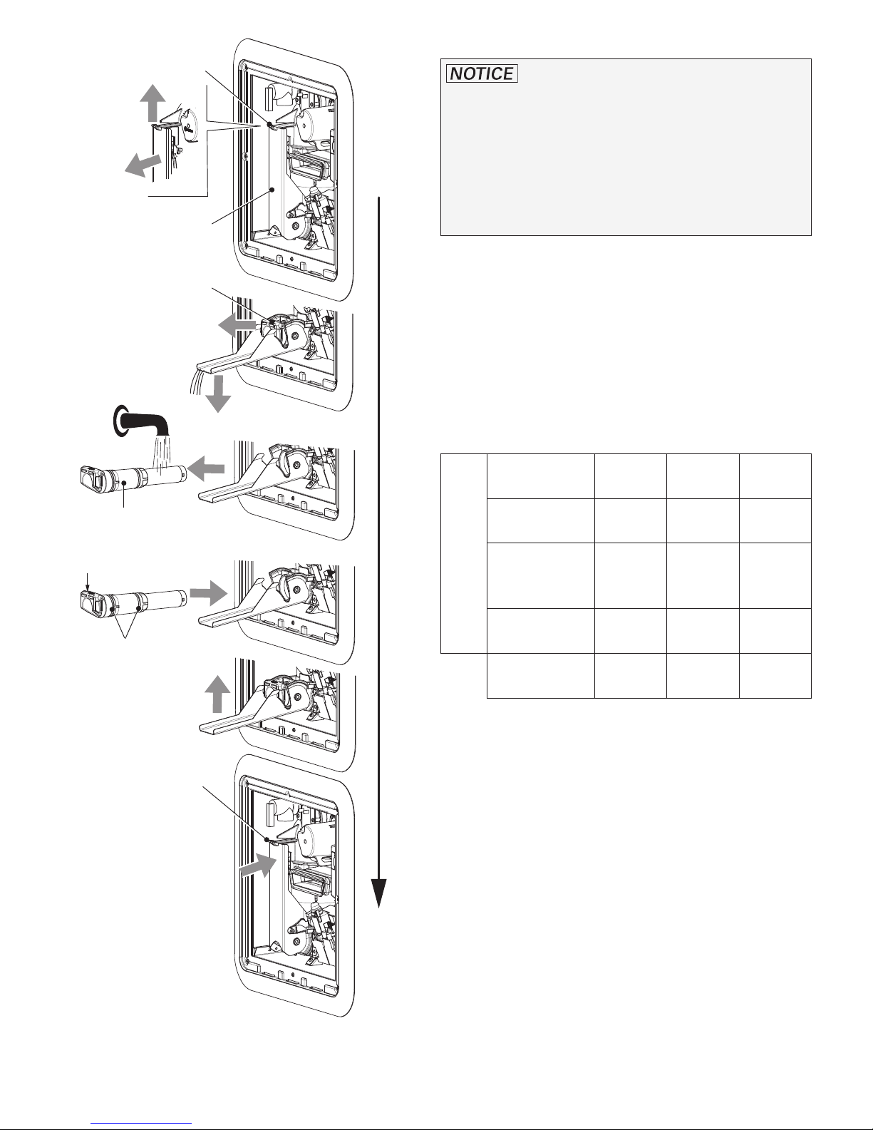
7. Open the latch with your thumb while pulling
the Easy Drain Lever down as far as it will go.
8. Remove the water inlet filter (or heating
cartridge) as shown in Fig. 10 and rinse it
with clean water.
Injuries caused by the Easy Drain Lever!
• Never actuate the Easy Drain Lever as long
as the appliance is under water pressure
and/or is still hot.
Sharp edges can cause cuts and injury!
• Always wear protective gloves to avoid
injuries from sharp edges during maintenance work.
Draining the water and cleaning the
water inlet filter
To keep the appliance fully functional, clean
the water inlet filter at least once a year.
1. AquaGo® comfort / AquaGo® comfort plus
Set the control panel to “Off”.
2. Remove the access door (refer to “Removing
the access door” on page9).
3. Switch OFF the appliance at the POWER
switch.
4. Open a hot water faucet and wait for cold
water.
5. Turn OFF the water supply or switch OFF the
water pump.
9. Inspect the O-rings on the water inlet filter
(or heating cartridge) for cracks. Change
the filter assembly (spare part, refer to “APPENDIX C – Spare Parts (all models)” on
page39) if there are cracks.
Danger of crushing/pinching of fingers
when the Easy Drain Lever is closed!
• Never put fingers between Easy Drain
Lever and water inlet filter or latch.
If, during installation, it is difficult to
install the filter cartridge, use a small
amount of soap on the O-rings. Never use
grease because the O-rings are not resistant
to grease.
10. Install the water inlet filter as shown in
Fig. 10. Observe the correct installation
position and close the Easy Drain Lever until
it is locked by the latch.
You can hear a “clicking” sound as the
EasyDrain Lever engages.
11. Insert and close the access door (refer to
“Closing the access door” on page9).
15
Page 16
Latch
Decalcification
I
II
Easy Drain Lever
Water inlet filter *
Water inlet filter *
Top
O-rings
Risk of damage in frosty conditions.
In frosty conditions there is a risk that water
in pipes, faucets and appliances could freeze.
This can cause considerable damage.
• Do not decalcify the appliance in frosty
conditions.
Decalcification frequency
Lime scale occurs especially as a result of
precipitation from “hard” water. The appliance
must be decalcified regularly depending on water hardness and hot water consumption.
Recommended decalcification frequency
per year
Very hard
>180
Hard
121 – 180
3
Moderately
hard
61 – 120
Soft
Water hardness
mg/l CaCO
0 – 60
Use* few normal fre-
1 2 4
1 1 3
1 1 2
1 1 1
quent
Latch
* or heating cartridge
Fig. 10
16
* Hot water consumption (approximately)
low 635 gallon/year 2400 l/year
normal 1585 gallon/year 6000 l/year
high 6350 gallon/year 24000 l/year
Page 17
Decalcification (models without
control panel)
Models AquaGo® basic without control panel:
You can have these models decalcified by
a Truma service partner. Please contact the
following address:
Truma Corp.
825 East Jackson Blvd.
Elkhart, IN 46516
USA
Toll Free 1-855-558-7862
Fax 1-574-538-2426
[email protected]
www.truma.net
Refer to “Decalcification frequency” on
page16 for the decalcification frequency.
Decalcification (models with
control panel)
AquaGo® comfort / AquaGo® comfort plus
with control panel (included with delivery).
The use of non original Truma AquaGo®
decalcification tablets (e.g. vinegar) for decalcification can cause chemical reactions
and produce hazardous substances that
could enter the drinking water supply.
• Do not mix Truma AquaGo® decalcification tablets with other substances to avoid
chemical reactions and production of hazardous substances.
• Only use Truma AquaGo® decalcification
tablets to decalcify the appliance to avoid:
– chemical reactions and production of
hazardous substances,
– damage to your appliance,
– and the voiding of your warranty.
– Call your local AquaGo dealer or ser-
vice provider or see www.truma.com
for more information to obtain
Truma AquaGo® decalcification tablets.
Irritation of skin and eyes in case of
contact with decalcification agent
Wear protective gloves, eye protection and
face protection to avoid contact.
An integrated water consumption meter recognizes (after hot water consumption of approx. 1585 gallons / 6000 l) that decalcification
is necessary. The assumed water hardness is
“hard” and cannot be changed. The yellow
status LED3 (Fig. 9) indicates that decalcification is necessary (goes off briefly about every
7 seconds).
• Never use the water supply in the RV during
decalcification
• In case of skin contact with the decalcification agent, immediately rinse the affected
area with plenty of water.
• In case of eye contact, hold eyelid open and
rinse with running water for 10 – 15min.
Remove contact lenses, if present and easy
to do. Continue rinsing. Consult an eye
specialist.
• If you swallow the decalcification agent,
immediately rinse your mouth and drink
plenty of water in small sips. Do not vomit.
Consult a doctor.
17
Page 18
During decalcification, you must also observe the following
• Damage to the appliance if decalcification is
interrupted.
– You must complete the decalcification
process and then rinse thoroughly with
clean water.
– Allow about 3 hours for decalcification.
The appliance works on its own for most
of this time.
• Sensitive surfaces (e. g. marble) may be
damaged through contact with the decalcification agent.
– Immediately remove splashes of decalcifi-
cation agent on these surfaces.
a) Preparing for decalcification
b) Draining the water system
Tasks outside the RV
• Remove the access door (refer to “Removing the access door” on page9).
• Switch OFF the appliance at the POWER
switch.
• Drain the water system and remove the
water inlet filter. Do do this, refer to “Draining the water and cleaning the water inlet
filter” on page15, Steps 4 to 8.
You must use the water inlet filter
for decalcification (included with the delivery
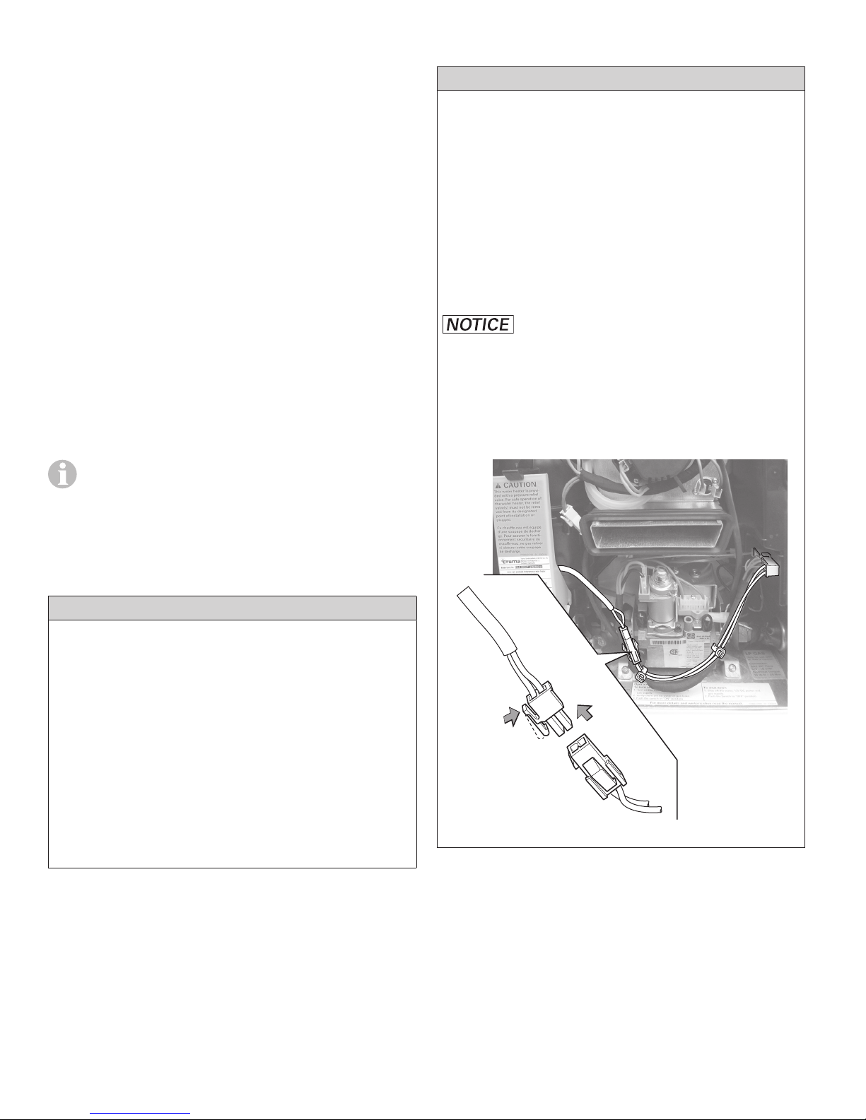
Fig. 1 – 11a). If you are using an electric antifreeze kit, it must be removed and be unplugged from the power supply before decalcification (see Fig. 11).
For safety reasons, once the decalcifica-
tion process has started it must not be
stopped until the system has been rinsed (see
process f). All operating modes of the appliance
are blocked until decalcification has been completed.
Tasks within the RV
• Set the control panel to “Off”.
• Turn OFF the water supply or switch OFF
the water pump.
• Open a hot water faucet to relieve pressure
in the system.
• On all water faucets attach the warning
sign “Caution decalcification in progress” in
a clearly visible position. Warning signs are
enclosed with the decalcification tablets.
Fig. 11
18
Page 19
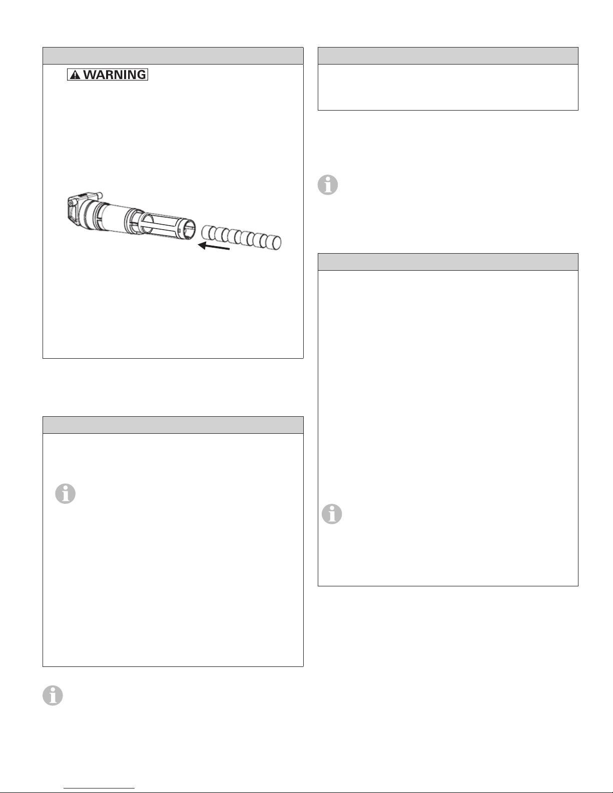
c) Introducing the decalcification agent
6 x
e) Starting decalcification
Tasks outside the RV
• Irritation of skin and eyes
in case of contact with decalcification
agent. Wear protective gloves, eye protection and face protection to avoid contact.
• Fill the water inlet filter with 6 Truma
AquaGo® decalcification tablets (content of
one blister pack).
Fig.12
• Re-insert the water inlet filter. See Step 9 in
“Draining the water and cleaning the water
inlet filter” on page15.
• Switch ON the appliance at the POWER
switch.
Tasks within the RV
• Set the control panel to “Clean”.
– If decalcification does not start, switch the
appliance on at the POWER switch.
f) Rinsing the water system
• You will need about 8 gallons of water
to rinse the water system.
• Dispose of (used) decalcification solution in accordance with local laws and
regulations.
Tasks within the RV
• Open all water-release points, e.g., hot water faucets, showers, toilets.
• Run the water until the status LED 3 (Fig.9)
on the control panel goes out.
• Set the control panel to “Off”.
d) Filling the water system
Tasks within the RV
• Turn on fresh water supply or switch on
water pump
The decalcification tablets dissolve in
water quickly (approx. 10 minutes). So
that the decalcification agent is not rinsed
out, when filling, run the water only as long
as necessary. The Truma decalcification tablets color the water slightly red.
• Fill the water system.
– Open all water-release points, e.g., hot
water faucets, showers, toilets.
– Once water flows uniformly, the water
system is vented.
– Close the water-release points.
• Close all water-release points.
• Turn OFF the water supply or switch OFF
the water pump.
• Open a hot water faucet to relieve pressure
in the system.
To make sure that the appliance and the
water pipes contain no decalcification
agent, empty the water system again and
refill it.
You must bleed the water system thoroughly otherwise the circulation pump can-
not circulate the decalcification solution.
19
Page 20
Tasks outside the RV
• Switch the appliance OFF at the POWER
switch (red error code LED 2 (Fig 8) flashes
before it switches off).
Interrupting decalcification
Decalcification is indicated through slow
flashing (1s on, 1s off) of the status LED 3
(Fig. 9) on the control panel.
• Drain the water System (refer to “Draining the water and cleaning the water inlet
filter” on page15, steps 4. to 8.).
• Install the water inlet filter* referring to step9.
* or antifreeze cartridge if electric antifreeze
kit is installed.
• Switch ON the appliance at the POWER
switch.
• Insert and close the access door (refer to
“Closing the access door” on page9).
You have to switch the appliance off and
on to unblock decalcification and enable
further operation.
• Decalcification can be interrupted by switching the control panel to “Off”.
– Decalcification is interrupted after about 2 s.
– The status LED 3 (Fig. 9) on the control
panel flashes quickly.
• Irritation of skin and eyes in
case of contact with decalcification agent.
Wear protective gloves, eye protection and
face protection to avoid contact.
• First you must take out the water inlet filter
and remove any Truma AquaGo® decalcification
tablets that it may contain.
– To take out the water inlet filter, see
“Draining the water and cleaning the water inlet filter” on page15.
– Dispose of Truma AquaGo® decalcification
tablets in accordance with local laws and
regulations.
g) Filling the water system
Tasks within the RV
• Turn on fresh water supply or switch on
water pump.
• Fill the water system.
– Open all water-release points, e.g., hot
water faucets, showers, toilets .
– Once water flows uniformly, the water
system is vented.
– Close the water-release points.
• Before you use the water system and the
appliance, check the color of the water at
all faucets:
– Slightly red –> rinse again.
– Clear –> decalcification is finished.
• Remove the warning signs “Caution decalcification in progress”.
• Before you use the water system again, you
must rinse it (see step f) “Rinsing the water
system” on page19) and fill it with water
(see step g) “Filling the water system” on
page20).
20
Page 21

Accessories
Electric antifreeze kit *
Truma offers an electric antifreeze kit (part no.
77400-01) that keeps the appliance frost-free
to -4 °F (-20 °C) while you are driving or if there
is no gas supply. To operate the kit, you need
a 12VDC (120W) power supply from the vehicle’s on-board system. Ask your dealer.
* For AquaGo® comfort / AquaGo® comfort plus.
Truma AquaGo® decalcification tablets
Truma offers decalcification tablets (part no.
77300-01) to decalcify AquaGo® comfort /
AquaGo® comfort plus.
Truma rear installation gas connection kit
Truma offers a rear installation gas connection
kit (part no. 77000-37500) if installation from the
back of the appliance is required.
Truma AquaGo® Comfort upgrade kit
Truma offers a kit (part. no. 77000-00005) to upgrade from AquaGo® basic to AquaGo® comfort.
21
Page 22

Troubleshooting
Problem Potential cause Resolution
No hot water at
the faucet
Gas supply is turned off or interrupted.
Gas tank is empty. Refill/replace the gas tank.
The appliance is switched off. Switch on the appliance according to
Fresh water supply is turned off. Open the fresh water supply.
Power supply to the appliance is
switched off.
Defect in the appliance. LED 2 blinks red (refer to “APPENDIX A –
Boiling noises Too much lime scale in the Truma
AquaGo® instant water heater.
Hot water temperature too low.
Gas flow to the appliance is too low
(gas inlet pressure < 10.5 in. wc).
Check and/or turn on gas supply.
instructions (refer to “Operating procedures” on page10).
Switch on power supply to the appliance.
Error Codes” on page37) and contact
a certified service technician if necessary.
The appliance must be decalcified (refer
to “Decalcification” on page16).
Consult vehicle documentation to
determine if gas supply is capable
of providing the necessary volume of gas for the appliance.
Volume flow of hot water is too
high and/or the temperature of cold
water reaching the appliance is too
low.
Too much lime scale in the appliance.
Contact a service technician to verify a suitable gas installation.
Turn down hot water at the faucet or in
the shower in order to reduce volume
flow.
Potentially retrofit a volume flow throttle
into the water system. This must be performed only by a certified service technician.
The appliance must be decalcified (refer
to “Decalcification” on page16).
22
Page 23
Problem Potential cause Resolution
Water escaping
at pressure relief
valve.
Water pressure in water system too
high.
Water cannot expand in the water
system.
Lime or dirt under the pressure
relief valve seat.
Adjust the water pump pressure to a
maximum of 65 psi (4.5 bar).
If the water system is connected to a central water supply higher than 65 psi (4.5bar)
(rural or urban connection), a pressure
reducer must be used.
Install a pressure reducer (e.g. Truma
pressure reducer) at the fresh water
supply.
Contact the vehicle manufacturer about
retrofitting a pressure compensation element.
Allow the appliance to cool and then
slowly raise the test lever (Fig. 3 – 4a)
to flush the water system and attempt
to force dirt or foreign matter out of the
pressure relief valve seat.
Water escaping
Lime or dirt under the O-ring seats. Clean the O-rings and their correspondat the water inlet
filter
AquaGo® comfort / AquaGo® comfort plus
The yellow status
Power switch is OFF. Switch ON the appliance at the POWER
LED 3 is off although an operating mode was
Power supply to the appliance is
switched off.
selected.
Power supply was interrupted. Reset by switching OFF at the con-
Replace pressure relief valve. This must
be performed only by a certified service
technician.
ing sealing surfaces with clean water.
switch.
Switch on the power supply to the appli-
ance.
trol panel, waiting 2 seconds and then
switching on again.
23
Page 24

TRUMA Gerätetechnik GmbH & Co. KG
(“TRUMA”)
“AquaGo” MANUFACTURER
LIMITED WARRANTY
(September 2014)
This limited warranty pertains solely to the
“AquaGo” (the “Product”) manufactured by
TRUMA and sold through its affiliates and dealers in North America.
TRUMA warrants subject to the below stated
conditions that the Product will be free from
defects in material and workmanship, and will
perform in accordance with the technical specifications set forth in the description of the Product for a period of twelve (12) months for newly
manufactured parts from the original date of
purchase. The original purchaser is advised to
register the Product within two (2) months of
purchase with www.truma.net in order to
receive an extended warranty of an additional
twelve (12) months. This limited warranty shall
only apply if the Product was properly installed
according to the installation instructions provided and in compliance with applicable codes.
During the warranty period, TRUMA will repair
or replace, at its own discretion and costs, the
defective Product or parts or components of
such Product reported to TRUMA and which
TRUMA determines was defective due to a warranty defect. Costs of diagnosis for a warranty
defect are borne by TRUMA. Other costs of diagnosis are not included in this warranty. At the
discretion of TRUMA, the replacement of the
Product or parts or components thereof (i) may
be newly manufactured, (ii) may be assembled
from new or serviceable used parts that are
equivalent to new parts in performance, or (iii)
may have been previously installed.
This limited warranty does not cover any defects attributable in whole or in part to (i)
non-TRUMA products and services and / or
alterations of out-of-specification supplies, (ii)
accidents, misuse, negligence or failure of the
customer to follow instructions for the proper
use, care and cleaning of the Product, (iii) damages caused in gas pressure regulation systems
due to foreign substances in the gas (i.e. oil,
plasticizers), (iv) external factors (e.g., fire, flood,
severe weather), (v) failure of proper transport
packaging, or (vi) failure by the purchaser to
comply with TRUMA’s installation and user
manual regarding the Product.
All warranty claims must be reported to
TRUMA’s authorized warranty service center in
the United States: Truma Corp Service Center,
825 East Jackson Blvd., Elkhart, IN 46516,
toll free: (855) 558-7862, fax. (574) 538-2426,
[email protected], www.truma.net
The purchaser shall provide the following
information regarding the potential warranty
claim (i) serial number of the defective device,
(ii) proof of purchase, (iii) purchaser’s contact
information.
EXCEPT AS EXPRESSLY STATED AND SET
FORTH HEREIN, THERE ARE NO WARRANTIES OR REPRESENTATIONS, EXPRESS OR
IMPLIED, CONCERNING THE PRODUCT
AND NO SUCH WARRANTIES OR REPRESENTATIONS SHALL BE IMPLIED UNDER
ANY APPLICABLE LAW, IN EQUITY OR
OTHERWISE, INCLUDING WITHOUT LIMITATION, A WARRANTY OF MERCHANTABILITY, A WARRANTY OF FITNESS FOR
A PARTICULAR PURPOSE, OR ANY OTHER
WARRANTY WHICH MAY BE IMPLIED UNDER COMMON LAW OR UNDER THE UNIFORM COMMERCIAL CODE OF ANY STATE
OR OTHER JURISDICTION OF THE UNITED
STATES OF AMERICA.
The customer shall not attempt to repair
the Product or resolve the problem without
the prior consent of TRUMA. Any attempt
by the customer to repair the Product or
resolve the problem without the prior consent of TRUMA will void this warranty.
24
Unless further limited herein, the entire liability
of TRUMA and the customer’s exclusive remedy
for damages from any cause related to or
arising out of a warranty defect, regardless of
the form of action, whether in contract or in
tort, will not exceed the amount of the purchase
Page 25

price for each purchase order for the Product
which is the subject matter or directly related to
the causes of action asserted.
Unless prohibited under applicable state law,
in no event will TRUMA, its agents, subcontractors, affiliates, suppliers and employees be
liable for (a) any incidental, indirect, special or
consequential damages, including, but not limited to, loss of use, revenue, profits or savings,
substitute rental or for any other reason, even if
TRUMA knew or should have known of the possibility of such losses or damages, (b) claims,
demands or actions against the customer by any
person, except as provided by applicable law.
Installation Instructions
Read, observe, and follow these safety
instructions to avoid injuries during installation or operation.
Safety behavior and practices
• Installation and service must be performed
by an authorized Truma recommended installer, service agency, or OEM. Improper installation, alteration, service, or maintenance
can cause property damage, personal injury,
or loss of life.
– Do not attempt installation as a Do-it-
Yourself project.
• Install in recreational vehicles (RVs) only.
– Install the appliance on an exterior wall,
with the access door opening to the
outside.
– Install the appliance in the shown orien-
tation.
• Switch off the vehicle’s on-board power supply during installation and when connecting
the appliance.
• Close the vehicle’s gas supply during installation and when connecting the appliance.
• Always wear protective gloves to avoid injuries from sharp edges during installation and
maintenance work.
• Handle the appliance only by lifting or grabbing the metal casing or cover plate. Never
lift or grab the appliance by any of its delicate interior components.
• Make sure that all combustion air is supplied
from outside the RV. DO NOT draw air for
combustion from occupied spaces.
25
Page 26
• Make sure that all exhaust gases are directed outside of the RV.
– Protect building materials from exhaust
gases.
– Never direct the exhaust gases to any out-
door enclosed spaces, such as a porch.
Selecting a suitable location
The appliance is designed to be installed on a
floor or a fixed platform with access to water.
Electrical connections are established at the
back. Gas access is from the side or from the
rear.
• Any alteration to the appliance or its controls
can cause unforeseen serious hazards and
will void the warranty.
• DO NOT alter the appliance for a positive
grounding battery system.
• DO NOT shorten the power cable or remove
the sticker that indicates polarity.
• DO NOT perform a hi-pot test on the appliance unless the electronic ignition system
(circuit board) has been disconnected. A
hi-pot test applies a very high voltage between two conductors.
• DO NOT use a battery charger to supply
power to the appliance, even when testing.
• If the vehicle requires welding, DO NOT connect the 12 V DC power to the appliance.
Electrical welding will cause serious damage
to the appliance controller.
United States and CANADA
This appliance must be installed in accordance
with local codes or, in the absence of local
codes, the Standard for Recreational Vehicles,
ANSI A119.2/NFPA 501C or CAN/CSA-Z240 RV.
The appliance is designed exclusively for installation on an outside wall of a RV.
Installation of the water heater on the back
of a trailer is not advised because of high
pollution caused, e.g., by dirty and wet roads.
Risk of poisonous exhaust gases due to
improper installation!
• Make sure that the appliance is installed as
described below.
• DO NOT install the appliance in any location
where the vent may be covered or obstructed when any door on the RV is opened or
due to the design of the RV or due to special
features of the RV such as slide-out, pop-up,
etc.
• DO NOT install on a swing door.
• DO NOT install the appliance under any
window, slide-out or opening into the RV in
order to prevent exhaust gases from entering
the RV.
• DO NOT install the appliance in such a way
that the cover plate is less than
– 1 foot (30 cm) from each side and top of
any window, slide-out or opening into the
RV,
– 6 feet (1.8 m) from any mechanical air
supply inlet or
– 3 feet (91 cm) from any gas tank connec-
tion or ventilation.
26
• Maintain a minimum clearance from combustible materials on sides, top, floor and
rear (0in.).
• Provide room for access to rear of appliance
for servicing.
Page 27
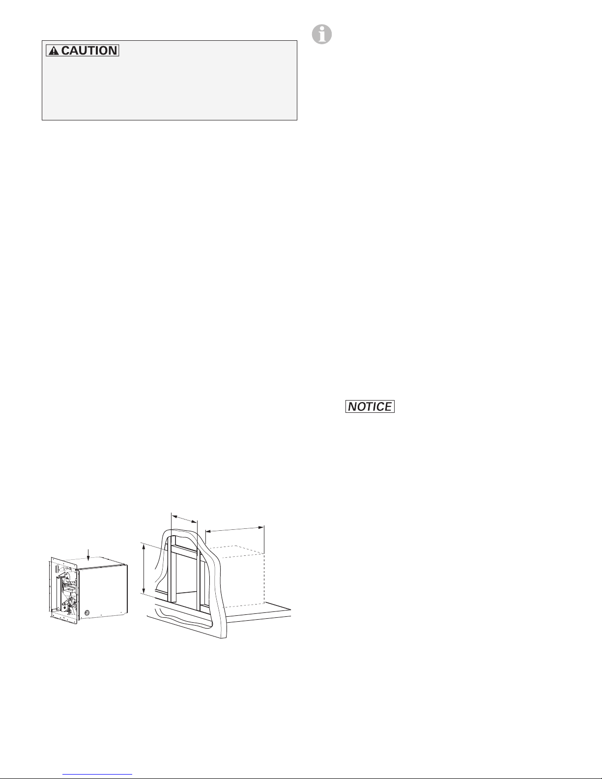
Preparing for installation
a
Sharp edges can cause cuts and injury!
• Always wear protective gloves to avoid injuries from sharp edges during installation
work and while handling the appliance.
Preparing the installation site
1. Make sure that the appliance is in contact
with the vehicle floor or a platform with
adequate weight-bearing capacity when
installed.
2. To install on a carpeted area, install a metal
or wood panel under the appliance that
extends at least 3 in. (7.6 cm) beyond the
width and depth of the appliance.
• The required depth “c” depends on
how the water hoses, electrical connection cable, and gas line are installed. The depth “c” must be determined
for the particular situation before
installation.
• The corners of the rough opening
must be at right angles. The exterior
wall opening must be the same dimensions with no rounded corners.
• An access door adapter kit is available
for replacing existing water heaters,
with a large cut-out in the outer wall of
the RV. The adapter plate must be installed before the appliance is installed.
The access door adapter kit includes
detailed installation instructions.
5. Make sure you have suitable screws ready:
3. If escaping water may damage components
or the vehicle, install a collection pan below
the appliance. Direct the flow of water from
the pan to outside the vehicle.
4. Make sure that the front edge of the opening is surrounded by a solid frame to firmly
anchor the appliance. If needed, build an appropriate frame (Fig. 13) with the following
dimensions:
Width a = 12.75 in. (324 mm)
Height b = 12.75 in. (324 mm)
Depth c = >17.7 in. (450 mm)
c
Top
b
• Without access door adapter kit
In order to securely fasten the appliance and
the cover plate, the screws must be suitable
for the chosen frame material and have a
diameter of 0.138 in. (#6) to 0.164 in. (#8).
– Never use countersunk screws
to secure the cover plate, as it will be
damaged (tear). Use pan head screws.
– For the length of the screws follow the
screw manufacturer’s guidelines.
• With access door adapter kit
You must use the 22 screws 0.164 (#8) x
0.51 in. (4.2 x 13 mm) that are included with
the access door adapter kit.
– 14 x for fixing: appliance with adapter plate.
– 8 x for fixing: cover plate with adapter plate.
Fig. 13
27
Page 28
Preparing the gas connection
Risk of explosion due to improper installation of the gas connection!
• Make sure that the operating pressure
of the gas supply corresponds to the
operating pressure of the appliance
10.5 – 14 in. wc (26.2 – 34.9 mbar).
For correct installation, you must also observe the following:
• The gas connection (SAE 45° Flare Male –
SAE J512, 5/8 in. – 18) is located inside the
appliance.
• Make sure that the gas line to the appliance is
able to supply the maximum required quantity of gas (≥ 60,000 BTU/h), without the gas
pressure on the gas connector of the appliance falling below 10.5 in. wc (26.2 mbar).
• Consider the space needed to lay the gas
line and integrate the appliance when planning the installation space.
• Guide the gas line into the installation space
so that the appliance may be removed and
reinstalled if service or repairs are needed.
• Allow sufficient length and flexibility in the
gas line for connection or disconnection of
the gas line.
• Reduce the number of separation points in
the gas line to the technically required number.
– Gas side connection
Risk of explosion due to improper installation of the gas side connection!
• Use rigid metal 3/8 in. pipes (complies to
1/2 in. (12.7 mm) outside diameter) for the
side gas connector of the appliance to the
gas system of the RV.
• In exceptions, flexible gas hoses may be
used for the side gas connector. The following 4 conditions must be met:
1. Guidelines, laws or regulations allow the
use of flexible gas hoses in this application.
2. The flexible gas hoses are certified for
this type of application.
3. The flexible gas hoses can be inspected
easily over their entire length.
4. New flexible gas hoses are used for the
installation.
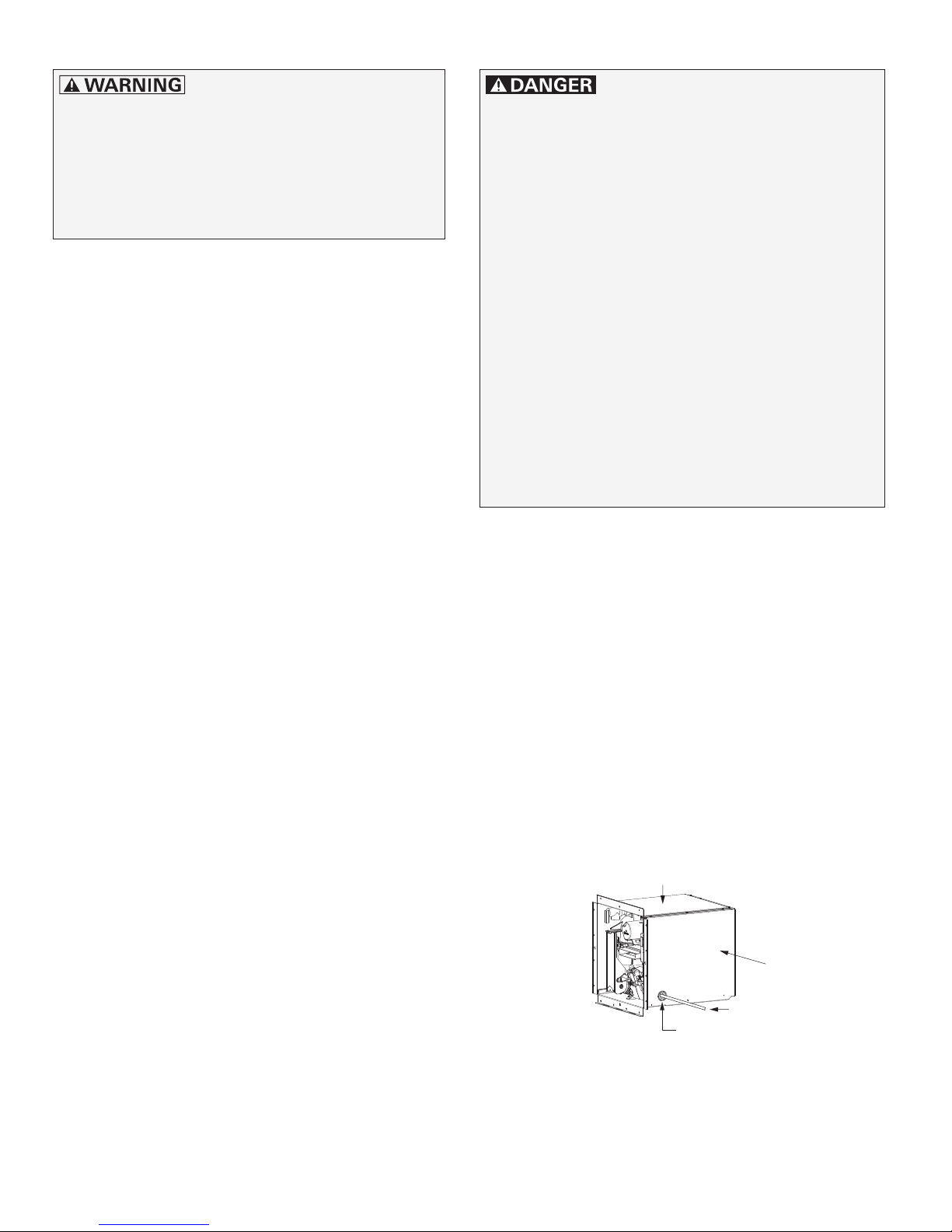
The gas line is guided into the appliance from
the side. A hole with a gas pipe grommet (side)
is provided in the unit casing for this purpose.
• Slide the appliance carefully into the installation space until the installation frame makes
contact.
• Make sure that the gas line connects vertically with the appliance’s gas connection
and without tension.
• If the connection is OK, push the gas line
back. It will be connected in a later step.
Top
• Avoid separation points in the gas line in
spaces used by people.
• Ensure that the gas connection from the
vehicle is in place before installing the appliance.
28
Side
Gas supply line
Gas pipe grommet (side)
Fig. 14
Page 29
– Gas rear connection
Risk of explosion when using flexible gas
hoses with a gas rear connection.
• Flexible gas hoses can leak due to the high
temperatures in the appliance.
• You must use rigid metal 3/8 in. pipes
(complies to 1/2 in. (12.7 mm) outside diameter) for a gas rear connection.
Truma offers a rear installation gas connection
kit (part no. 77000-37500) if installation from the
back of the appliance is required.
Scope of delivery:
– A brass elbow with a 45° SAE flare style
fitting,
– a plug,
– a gas pipe grommet (rear) and
– a cable tie are included.
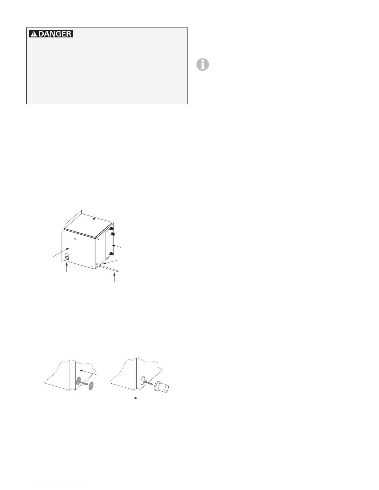
Top
Preparing the water connection
All water connections on the appliance are
1/2 in.NPT male connections.
• Use only pressure pumps in the water
system, not immersion pumps, as air
in the water system could cause malfunctions.
• The network of lines must be planned
before installation (refer to “Connection diagrams” on page31).
• Keep the length of the water pipes as
short as possible.
• Because of the risk of frost, install
water pipes only in adequately heated
areas of the RV.
• Avoid thermal bridges.
• Install water pipes in a rising direction
so that air in the pipes can escape.
• For AquaGo® comfort plus
Protect the circulation line against
heat loss with sufficient insulation
material.
Rear
Side
Gas pipe grommet
(side)
Gas pipe grommet
(rear)
Gas supply line
Rigid (metal) 3/8 in. pipe
Fig. 15
• Open the pre-punched hole on the rear side
of the appliance.
• Insert the gas pipe grommet (rear) in this
hole (pay attention to the direction).
Rear
I II
Fig. 16
• Use a suitable connector with a seal for
establishing the water connection to the appliance.
• Use of flexible water hoses of at least
1/2 in.diameter is preferred.
• Make sure that all water hoses are installed
without kinks.
• Make sure that the water connections from
the vehicle are in place before installing the
appliance.
29
Page 30
Preparing the 12 V DC electrical
connection
All electrical connections must be made in
compliance with all national, regional or local electrical codes.
Risk of a short circuit and hazardous situations due to improper installation of the
electrical connection!
• Use only insulated terminals for all electrical connections.
• The positive line must be fused with a 7.5A
fuse near the battery’s positive terminal.
• The power supply cable must have a diameter of at least:
– 16 AWG (1.5 mm² MWG) for up to
40 ft (12 m) length (bidirectional)
– 14 AWG (2.0 mm² MWG) for up to
66 ft (20 m) length (bidirectional)
• Establish the 12 V DC electrical connections
according to the connection diagram see
“Electrical connection for all models” on
page31.
• To ensure reliable operation:
– Provide a constant voltage supply.
– Filter any AC spikes or voltage surges.
– The AC voltage ripple must not exceed
1 Vpp.
Mounting the control panel
Only AquaGo® comfort /
AquaGo® comfort plus
• Damage to the control panel
from wetness and moisture. You must
install the control panel at a place inside the
RV that is protected against moisture and
wetness.
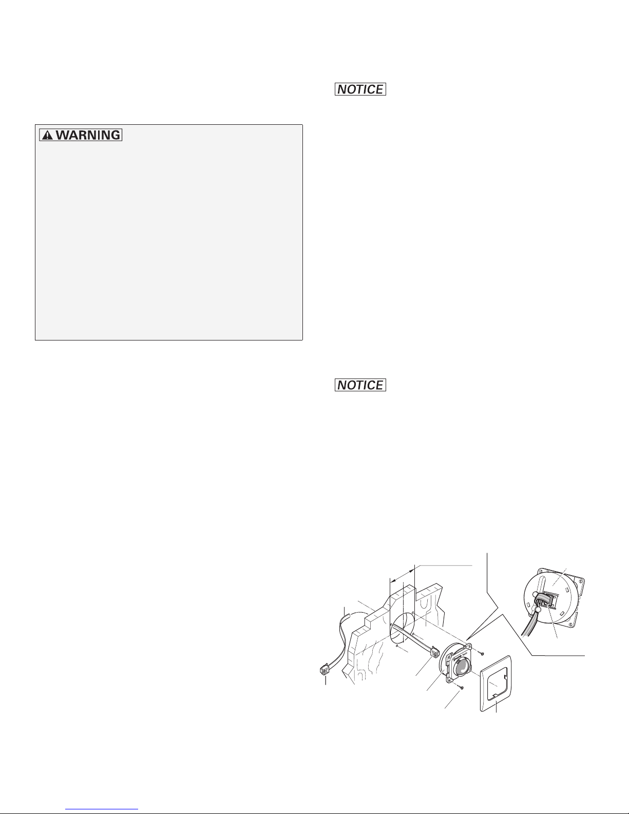
• Install the control panel (Fig. 17- 27) where it
can be seen easily.
– A 9 m control panel cable (27a) is includ-
ed with the delivery.
• Drill a 2 1/8 in. (54 mm) diameter hole.
• Insert the plug (27b) on the control panel (27)
until it clicks into place.
• Clamp the control panel cable (27a) in the
cable duct of the control panel.
• Damage to the control panel
cable at temperatures above +60 °C. Do
not install the control panel cable on or fix it
to hot components.
• Slide the control panel cable to the back and
lay it to the appliance.
• Fix the control panel with 4 screws (27d).
• Make sure that the electrical connections
from the vehicle are in place before installing
the appliance.
30
• Install the cover frame (27e).
Ø 2 1/8 in.
(54 mm)
27a
27c
27b
27
27d
Fig. 17
27
27b
27e
Page 31
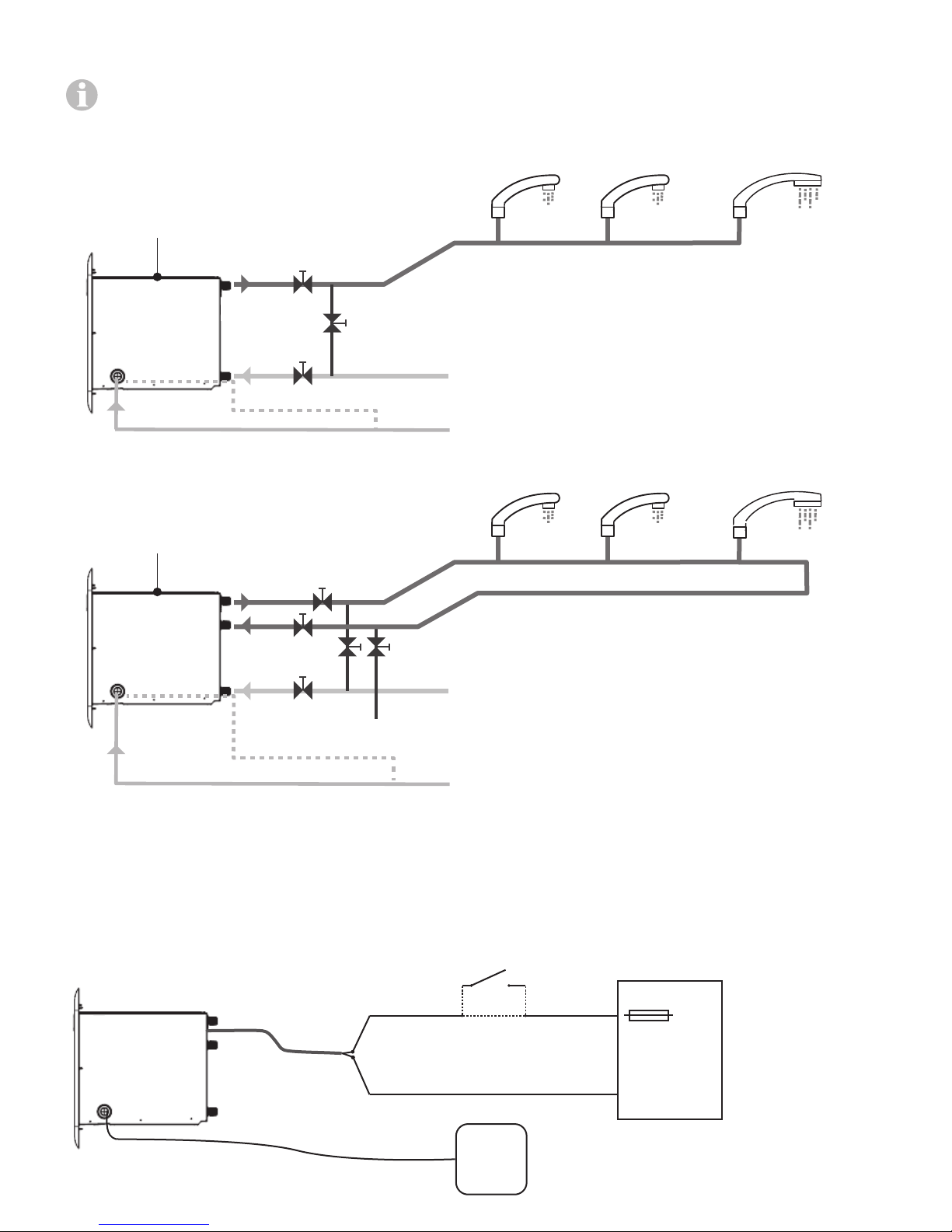
Connection diagrams
• The drawings are not intended to describe a complete system. It is up to the certified service technician to determine the necessary components for and configuration of the particular system being installed (for example an additional surge protector).
• The drawings do not imply compliance with state or local code requirements or regulations. It is the certified service technician’s
responsibility to make sure that the installation is in full compliance with all state or local code requirements or regulations.
Model AquaGo® basic / AquaGo® comfort
Top
Hot Water
Outlet
A*
Faucet 1 Faucet 2 Shower
Instant
Water Heater
Gas side connection
Cold Water
Inlet
Gas rear connection
B*
Fig. 18
Model AquaGo® comfort plus
Top
Hot Water
Outlet
E*
Instant
Water Heater
Gas side connection
Circulation
Line Inlet
Cold Water
Inlet
Gas rear connection
C* D*
B*
Fig. 19
A*
C*
Drain Line
* Bypass kit for winterizing (not in scope of delivery)
Maximum pressure 65 psi (4.5 bar)
LP gas supply (propane only)
Inlet pressure 10.5 - 14 in. wc (26.2 - 34.9 mbar)
Faucet 1 Faucet 2 Shower
* Bypass kit for winterizing (not in scope of delivery)
Maximum pressure 65 psi (4.5 bar)
LP gas supply (propane only)
Inlet pressure 10.5 - 14 in. wc (26.2 - 34.9 mbar)
Electrical connection for all models
Maximum length of the power supply cable (including cables for the optional switch):
• for 16 AWG or 1.5 mm² MWG: max. 40 ft (12 m) (bidirectional)
• for 14 AWG or 2.0 mm² MWG: max. 66 ft (20 m) (bidirectional)
Optional:
Instant
Water Heater
Fig. 20
Switch ON - OFF
(Rating: ≥ 7.5 A)
+
-
12 V DC
Ripple < 1 V
Control
Panel * /
Diagnosis
+
7.5 A
pp
12 V DC
Power
Supply
-
* only AquaGo® Comfort and
AquaGo® Comfort Plus
31
Page 32
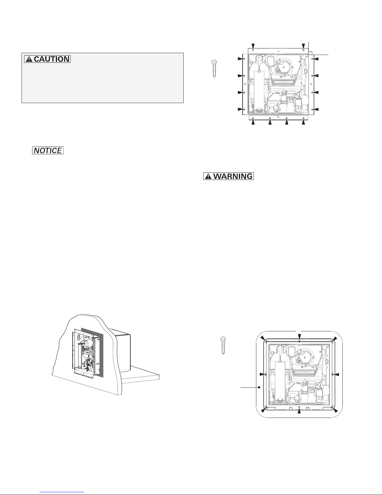
Installing the appliance
Before installation, read “Preparing for installation” on page27 and the following.
Sharp edges can cause cuts and injury!
• Always wear protective gloves to avoid injuries from sharp edges during installation
work and while handling the appliance.
• Slide the appliance carefully into the installation space until the installation frame makes
contact.
• Make sure that the unit casing corners are
90 degrees square so that the cover plate/access door fits properly.
90 degrees
14 x
Fig. 22
• Damage to the appliance and/
or the RV! Do not use adhesive sealing ma-
terial (e.g. silicone) for the watertight seal.
Otherwise damage may occur when the appliance is moved during servicing.
• The appliance must be installed with a watertight seal with the outer skin of the vehicle.
To achieve the watertight seal:
– Pull the appliance out ≈ 2 in. (5 cm).
– Apply an adequate amount of watertight
sealing material to the entire flange area
of the installation frame and at the corners, see gray marking in Fig.21.
– Slide the appliance carefully into the
installation space until the installation
frame makes contact.
• Immediately remove all excess sealing material.
• Risk of death from poison-
ing and significant damage to the RV
due to exhaust gas and leaking water!
– Make sure that there is a tight seal and
that no exhaust gas or water can enter
the RV.
• Check and make sure that there is a tight seal.
• Fasten the cover plate to the appliance (see
Fig.23):
– Position the cover plate.
– Screw the cover plate only loosely.
Start with screw 1.
– Align the cover plate.
– Uniformly tighten all 8 screws.
1
Fig. 21
• Screw the appliance into the vehicle’s frame
with the prepared 14 screws. See 5. “Make
sure you have suitable screws ready:” on
page27.
32
8 x
Cover plate
Fig. 23
Page 33
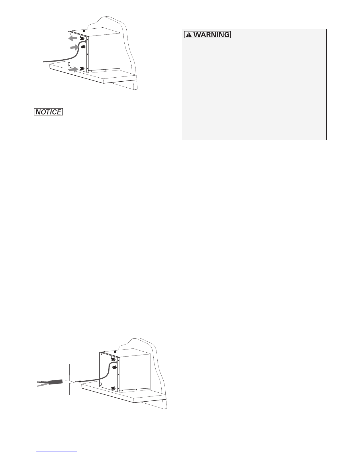
Top
Gas connection
2
3
1
Fig. 24
• Damage to the appliance and
the connections!
– Make sure that no gas lines, water hoses
or electrical lines are kinked or pinched.
– When establishing the water connections,
observe the installation instructions and
torques specified by the manufacturer.
• Connect the hose for cold water (1) at the
bottom of the appliance.
• Connect the hose for hot water (2) at the top
of the appliance.
Risk of explosion or poisoning due to
improper installation!
• Permit only a certified service technician
to perform installation.
• Make sure that the manual shut-off valve
in the gas line of the appliance is closed.
• Make sure that the gas line is centered
and tension-free when it enters the grommet so that the gas line will not abrade
the grommet.
• Make sure that the gas line has an
SAE 45° Flare Female connector.
Additional rules for the appliance gas connector.
• Make sure that the gas line is free of dirt,
chips, etc.
• Never use pipe dope on a flare fitting. The
flare fitting is a dry seal.
• Model AquaGo® comfort plus only:
Connect the hose for the circulation line (3).
• Check all connections for water leaks.
– Repair leaks as needed.
– Repeat check for water leaks and take
any necessary steps to repair the leaks at
all water connections.
• Connect the electrical lines with the proper
polarity to the 12 V DC power supply. Refer
to “Electrical connection for all models” on
page31). Install a 7.5 A fuse (see Fig. 20).
Top
12 V DC
+ red
Connecting the gas line (gas side
connection)
• Only AquaGo® comfort /
AquaGo® comfort plus (with control panel)
– Feed the control panel cable (approx.
10 in. (25 cm)) from outside through the
gas pipe grommet (side).
– Attach the control panel cable to the con-
trol unit.
– Hook the control panel cable on to the clip.
• Guide the prepared gas line through the gas
pipe grommet (side).
• Screw the gas line’s union nut (wrench size
3/4 in. (19 mm)) onto the appliance’s gas
connection so it is finger-tight.
– black
Fig. 25
33
Page 34

Connector
SAE 45° Flare Female
Connecting the gas line (gas rear
connection)
• Remove the gas pipe grommet (side).
Clip
Control panel cable
LP gas supply
Fig. 26
• Gas valve may be damaged
during tightening! Use a second wrench to
counterhold at the square end (wrench size
11/16 in. (18 mm)).
• Use a torque wrench to tighten the union nut
(nominal torque 15 lb-ft (20 Nm)).
• Risk of poisoning and/or
explosion! Improper tightening of the cable
tie could result in gas/exhaust entering the RV.
• Close the cable tie so that the gas pipe
grommet (side) tightens the gas pipe passage (see Fig. 27).
A cable tie is provided with the appliance.
You will find it fixed to the gas valve.
Control panel cable *
Cable tie
• Slide the prepared gas pipe through the gas
pipe grommet (rear) from behind so that the
elbow fitting can be mounted.
Gas pipe grommet
(side)
Fig. 28
• Gas line may be damaged during tightening! Use a second wrench to
counterhold at the square end (wrench size
9/16 in. (14 mm)).
• Mount the elbow union (45° SAE flare style)
on the gas pipe in the direction shown (see
Fig. 29).
• Use a torque wrench to tighten the union
nut (nominal torque 15 lb-ft (20 Nm)) (brace
against the elbow union with wrench size
9/16 in. (14 mm)).
SAE 45° Flare Male
SAE J512, 5/8 in. -18
SAE 45° Flare Female
SAE J512, 5/8 in. -18
* AquaGo® comfort / AquaGo® comfort plus
Fig. 27
34
Gas pipe
grommet (side)
Fig. 29
Page 35
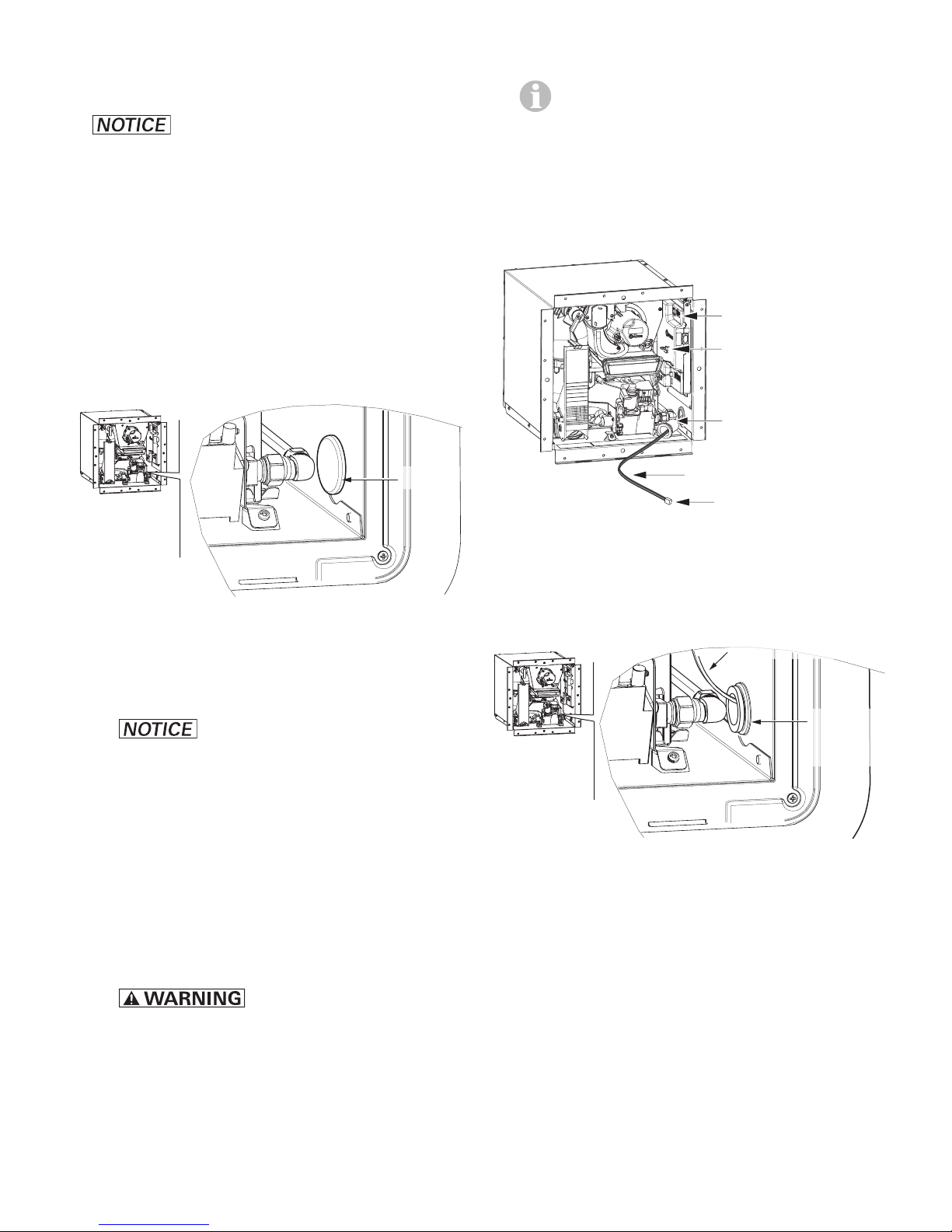
• Screw the gas line’s union nut (wrench size
Connector
Control panel cable
3/4 in. (19 mm)) onto the appliance’s gas
connection so it is finger-tight.
• Gas valve may be damaged
during tightening! Use a second wrench to
counterhold at the square end (wrench size
11/16 in. (18 mm)).
• Use a torque wrench to tighten the union nut
(nominal torque 15 lb-ft (20 Nm)).
– Fix the side gas pipe grommet to the con-
trol panel cable with a cable tie.
A cable tie is provided with the appliance.
You will find it fixed to the gas valve
– Attach the control panel cable to the con-
trol panel.
– Hook the control panel cable on to the clip.
• Only AquaGo® basic (without control
panel):
– Close the side hole with the plug.
Plug
Fig. 30
• Only AquaGo® comfort / AquaGo® comfort plus (with control panel)
– Damage to the control panel
cable at temperatures above +60 °C.
Do not install the control panel cable
through the rear gas pipe connection. You
must feed the control panel cable through
the hole on the side.
Control unit
Clip
Gas pipe grommet
(side)
Control panel cable
length 25 cm
Fig. 31
– Install the side gas pipe grommet with
the control panel cable in the side hole.
Gas pipe
grommet
(side)
Fig. 32
– Slide the side gas pipe grommet on to the
control panel cable (bush points towards
hole). The control panel cable must protrude by about 25 cm.
– Risk of poisoning and/
or explosion! Improper tightening of the
cable tie could result in gas/exhaust entering the RV. Close the cable tie so that
the side gas pipe grommet tightens the
control panel cable passage.
35
Page 36
Checking for gas leaks
Functional check
Risk of death and personal injury through
fire and/or explosion!
• DO NOT use matches, candles or other
sources of ignition when checking for gas
leaks.
• After the gas supply is connected, check
for gas leaks at all gas connections. Use a
gas leak detection liquid.
1. Turn OFF the electrical power supply
2. Damage to the appliance from
test pressure higher than 60 in. wc
(150mbar). Ensure that the test pressure is lower than 60 in. wc (150 mbar).
3. Turn on the gas.
4. Check the appliance and all gas connections
for gas leaks with leak detection liquid.
– Bubbles indicate a gas leak that must be
repaired.
1. Bring the appliance into operation (refer to
“Starting the appliance” on page9).
2. Check the appliance for proper functionality.
If faults occur during operation of the
appliance, refer to “Troubleshooting” on
page22.
3. Provide operating and installation instructions to the vehicle owner.
The appliance is now ready for normal operation
and use.
5. Repair gas leaks as needed.
6. Repeat check for gas leaks at all gas connections.
36
Page 37
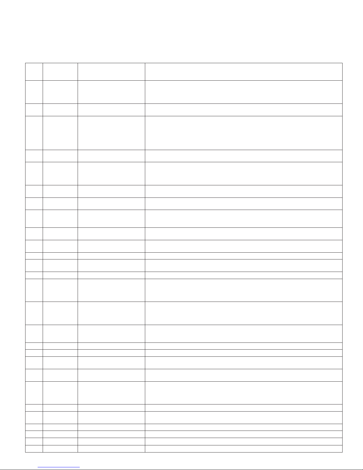
APPENDIX A – Error Codes
If the appliance malfunctions, LED 2 (refer to “Overview / Designation of parts” on page2) will blink to indicate the malfunction.
There are short and long intervals of blinking. The blinking will repeat every 3 seconds.
1. Write down the blinking intervals and check the list below.
2. Reset the appliance:
– Switch off the appliance. / – Wait 5 seconds / –Switch the appliance on again.
3. If an error code is still displayed, contact an authorized Truma service center.
Error
Blink code
code
s =short = 0
l = long = 1
1 s,s,s,s,s,s,s,l Flame not detected There is a flame-detection error at the burner because the flame was not de-
2 s,s,s,s,s,s,l,s Error at over temperature
3 s,s,s,s,s,s,l,l Error at exhaust pressure
4 s,s,s,s,s,l,s,s Error at water over tem-
5 s,s,s,s,s,l,s,l Flame detected at incor-
6 s,s,s,s,s,l,l,s Error in the safety circuit
7 s,s,s,s,s,l,l,l Error of burner MCU
9 s,s,s,s,l,s,s,l Malfunction of water
10 s,s,s,s,l,s,l,s Error in the safety circuit There is a heating request but gas is not released because a valve-actuation
11 s,s,s,s,l,s,l,l Error of MCU watchdog
12 s,s,s,s,l,l,s,s Internal error
13 s,s,s,s,l,l,s,l Short circuit shut-off valve Short circuit detection in the gas valve (shut-off part) detected a current
16 s,s,s,l,s,s,s,s Malfunction of the MCU Internal error of the control unit.
20 s,s,s,l,s,l,s,s Malfunction of water inlet
21 s,s,s,l,s,l,s,l Malfunction of circulation
22 s,s,s,l,s,l,l,s Malfunction of gas valve,
23 s,s,s,l,s,l,l,l Voltage is too high The main power supply’s voltage detector measured a voltage level of >16.4 V.
24 s,s,s,l,l,s,s,s Voltage is too low The main power supply’s voltage detector measured a voltage level of <10 V.
25 s,s,s,l,l,s,s,l Flue fan current con-
26 s,s,s,l,l,s,l,s Circulation pump current
27 s,s,s,l,l,s,l,l Water circulation pump is
28 s,s,s,l,l,l,s,s Too low gas pressure. Gas supply (in vehicle) to the appliance insufficient.
29 s,s,s,l,l,l,s,l Too high heat power
30 s,s,s,l,l,l,l,s Risk of freezing. Temperature in the appliance below 27 °F (3 °C).
31 s,s,s,l,l,l,l,l Decalcification finished. –
32 s,s,l,s,s,s,s Current too low. Current in the antifreeze kit too low (e.g. cable break).
33 s,s,l,s,s,s,s,l Current too high. Current in the antifreeze kit too high (e.g. short circuit).
Error Description
tected after release of gas and ignition.
Important: The system indicates this error only after three attempts at intervals
of approximately 30 seconds.
switches (EOS, BOS)
switch (EPS)
perature switch (WOS)
rect time
for gas valve
internal RAM
outlet temperature sensor
WOT
gas release
temperature sensor WIT
line temperature sensor
WCT
modulation section
sumption error
consumption error
running dry.
required.
The exhaust over temperature switch (EOS) or burner over temperature switch
(BOS) is open/unplugged.
The EPS did not close when the flue fan was actuated because the fan did not
push enough air through the exhaust channel. A cause could be, e.g., blocking
of the exhaust channel or a faulty switch.
OR
The EPS is closed even though the flue fan is not running. Cause is a defective
EPS or flue fan.
The WOS opened at a water temperature of over 185°F (85°C).
There is an error in flame detection of the burner because the flame was detected
– before ignition or
– before the release of gas or
– after the gas was switched off.
There is a heating request but gas cannot be released.
One of the switches WOS, EOS, BOS, EPS is open/unplugged.
Error detected in the burner MCU’s internal safety monitoring feature (safety
variables are no longer correct or RAM/STACK was overwritten by mistake).
Water outlet temperature sensor WOT
– has a short circuit or
– is open/unplugged.
signal was not activated.
There is a heating request but the MCU watchdog does not release the gas
path.
>1000 mA and shut off.
Water inlet temperature sensor WIT
– has a short circuit or
– is open/unplugged or
– the temperature of the sensor is colder than 14°F (-10°C).
Circulation line temperature sensor WCT
– has a short circuit or
– is open/unplugged or
– the temperature of the sensor is colder than 14°F (-10°C).
Error at gas valve, modulation level, because
- the modulator has a short circuit or
- is open/unplugged.
The current detector for the flue fan has measured a current outside the permitted limits.
The current detector at the circulation pump has measured a current outside the
permitted limits.
The circulation pump does not generate water flow. The water system may not
be filled or not sufficiently vented.
The circulation pump tries (20 times) to generate a water flow every 30 s (if
successful, the error is reset).
You are trying to use more hot water than the appliance can supply.
37
Page 38
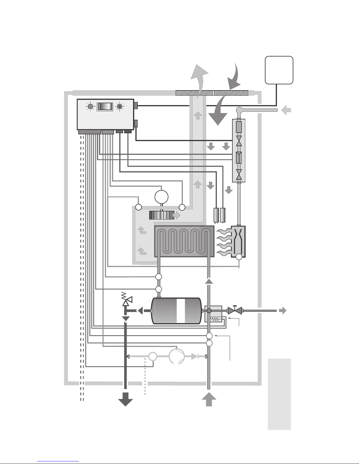
Casing
Ci
Line**
Combustion
APPENDIX B – Functional Diagram
Access
Door
Error
Power ON
Control Unit
LED 1
Power
Switch
Code LED 2
Exhaust
Outlet
Flue Duct
Control
Panel * /
Air Inlet
Filter
Gas Valve
Valve
Safety
Modulator
Valve
Safety
Diagnosis
Gas
Inlet
Exhaust
Relief
Pressure
Valve
Over Temp.
Switch
Flue
Flue
Fan
Fan
Wheel
Heat
Exchanger
MOT
Exhaust
Water
Over
Temp.
Water
Outlet
Temp.
Circulation
Line Temp.
Sensor *
Pressure
Switch
Sensor
Sensor
stabilizer
Temperature
Circulation
Pump *
*
Non-Return
Valve
Flame
FIE
Water
Flow
Rectification
Water
Sensor
Water
Electrode
Burner
Burner
Drain
Lever
Anti Freeze
Element *
Inlet Temp.
Sensor
Over
Temp.
Switch
(optional)
Water Drain
+12 V
Ground
Fig. 33
38
Hot
Water
rculation
Outlet
Cold
Water
Inlet
AquaGo® comfort plus
only
only AquaGo® comfort and
*
**
AquaGo® comfort plus
Page 39
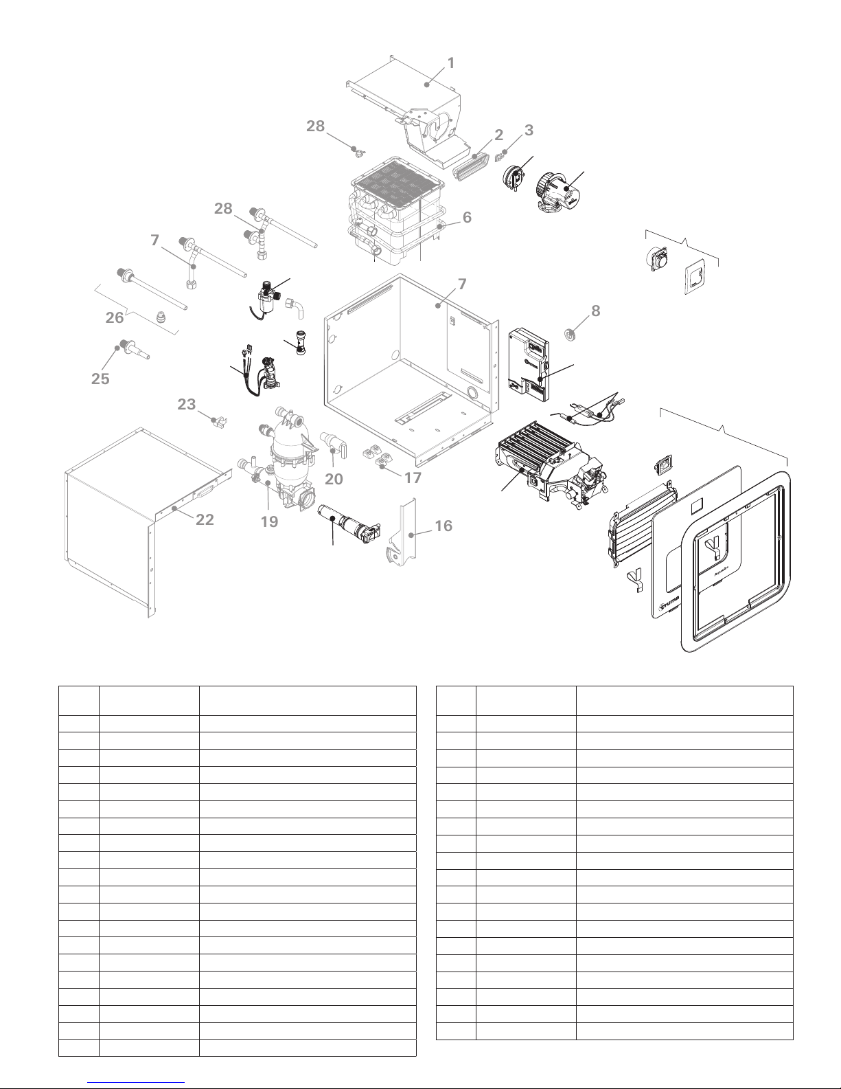
APPENDIX C – Spare Parts (all models)
1
25
26
27
23
22
28
24
30
19
29
28
20
3
2
4
5
6
38
7
8
9
10
35 (36, 37)
17
15
16
Fig. 34
Item
Ref.
10 77000-91300 Electrodes
11 NYA Flame rectification
12 NYA Access Door
13 NYA Venting Grid
14 NYA Slide latch
15 77000-90400 Burner Assembly
16 NYA Lever
17 NYA Spacer Set
18 77000-90800 Filter Assembly
19 NYA Temperature stabilizer Assembly
20 NYA Relief Valve
Part no. Component
1 NYA Flue Duct Assembly
2 NYA Flue Duct gasket
3 NYA Air Overheat Switch
4 77000-90100 Exhaust Pressure Switch
5 77000-90200 Flue Fan Assembly
6 NYA Heat Exchanger
7 NYA Lower housing Assembly
8 NYA Grommet
9 77000-00113 Control Unit Assembly
18
Item
Ref.
21 – –
22 NYA Upper housing Assembly
23 NYA Water temperature sensor
24 77000-90500 Flow Sensor Assembly
25 NYA Water connector
26 NYA Piping "Basic“
27 NYA Piping "Comfort“
28 NYA Piping "Comfort Plus“
29 77000-90600 Circulation Pump
30 77020-03500 Non-Return Valve Assembly
31 NYA Water overtemperature switch
32 NYA Cable harness 1 (not shown)
33 NYA Cable harness 2 (not shown)
34 NYA Small parts (not shown)
35 77001-01 Access Door Standard
36 77101-01 Access Door Adapter (not shown)
37 77201-01 Access Door XS (not shown)
38 77000-00089 Control panel
39 77000-00114 Sticker set (not shown)
Part no. Component
39
Page 40
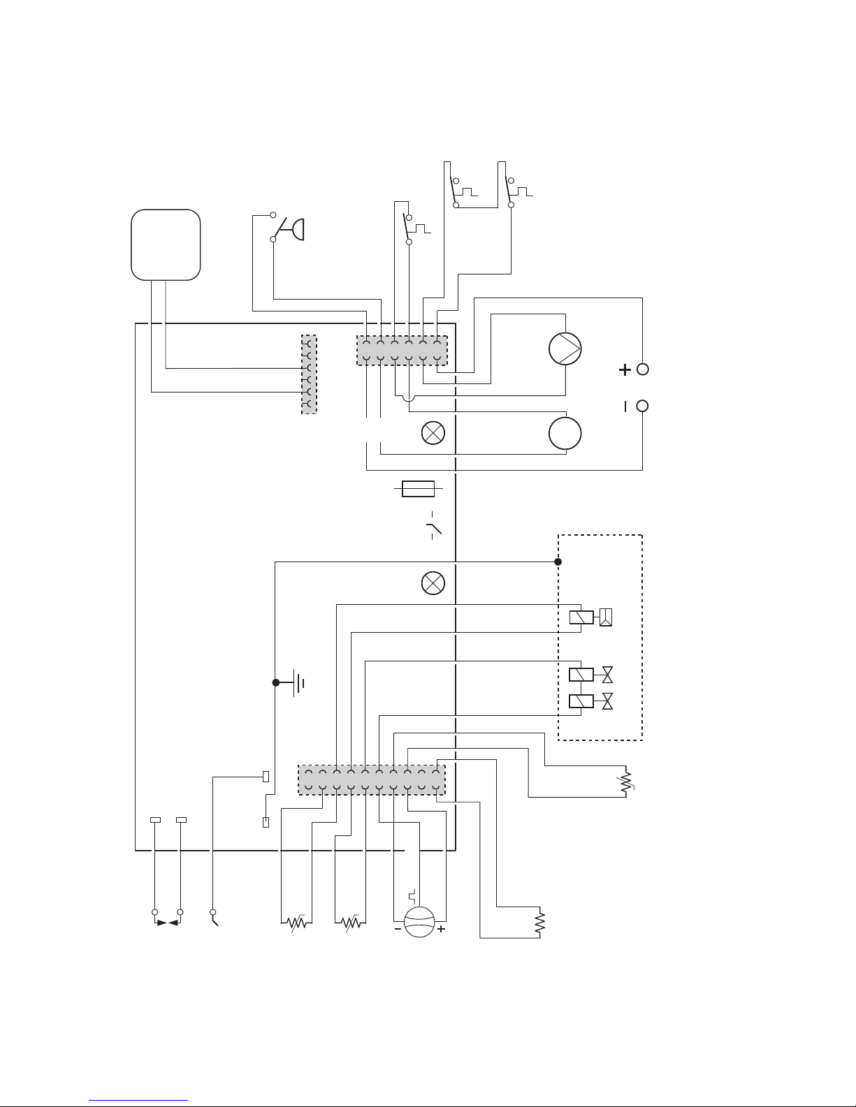
APPENDIX D – Electrical Connection Diagram
18 AWG or 1 mm2 MWG (** 16 AWG or 1.5 mm2 MWG)
Exhaust
(black)
(red)
(blue)
(orange)
Control
Panel * /
Diagnosis
Exhaust
(grey)
(white)
Pressure
Switch - EPS
Water
Over Temperature
Switch - WOS
(violet)
(10 A)
Internal Fuse
Burner
Over Temp.
(green)
(brown)
(yellow)
Error Code LED
Switch - BOS
Over Temp.
Switch - EOS
Circulation
MOT
Flue
Pump*
Fan
(red **)
(black **)
* only AquaGo™ Comfort and
12 VDC
AquaGo™ Comfort Plus
Ground
(orange)
-t°-t°
(green)
( white)
Power Switch
Power ON LED
(black)
(black)
(orange)
( blue)
( red)
Safety Valve Modulator
Gas Valve
(black)
(brown)
(blue)
(yellow)
(red)
(grey)
-t°
Circulation Line
Temperature
Sensor - WCT *
Flame Rectification
Flame Ignition
Electrode - FIE
Electrode - FRE
Water Outlet
Temperature
Fig. 35
40
Sensor - WOT
Water Inlet
Temperature
Sensor - WIT
Water Flow
Sensor - WFS
Anti Freeze
Element *
(optional)
If any of the original wire as supplied with the water heater
must be replaced, it must be replaced with wire 18 AWG (** 16 AWG) - 105 °C - UL1015, or its equivalent
Page 41

APPENDIX E – Notes for painting the access door and cover plate
• Using a Torx T-15 remove the 4 screws
Important Information
Observe all safety notes/instructions for
painting the access door and cover plate.
The following parts (see Fig. 37) may be
painted:
securing the venting grid to the access
door.
• After removing the screws, depress the
four (4) clips on the side of the venting
grid and remove it as shown in Fig. 36.
• The white cover plate
• The white outer surfaces of the access door
Material of the parts:
• The parts are made from a polycarbonate
material.
• Check whether the paint to be used is suitable for polycarbonate.
• For optimum adhesion of the paint it may be
necessary to apply a primer to the surfaces
that will be painted.
• Use of unsuitable paints may
damage the parts. Follow the recommendations of the paint manufacturer.
The following parts (see Fig. 36) must not
be painted:
3. Remove the turn lock:
To remove the turn lock, depress the four (4)
clips and remove it as shown in Fig. 36.
4. Mask the venting grid opening from the back
side (side with waffle pattern).
5. Close the access door and fix it in the closed
position for painting.
• This can be done with help of tape that
joins the flue fan and the edge of the turn
lock opening (see Fig. 37 for this detail).
• Remove any tape that hangs over the
edge by more than 0.12 in. (3 mm).
• Finally mask the turn lock opening with
tape (hatched area). Take care not to exceed 0.12 in. (3 mm) from the edge (this
is the area that will be covered by the
turn lock).
• The black venting grid
• The turn lock
• The webbings
Work before painting
In order to simplify painting and reduce the
work for masking, the turn lock and the
venting grid can be removed/disassembled.
Please follow the steps below to remove
the venting grid and the turn lock:
1. Open the access door.
2. Remove the venting grid:
6. Paint the access door and the cover plate.
Work after painting
7. Remove all masking.
8. Assemble the venting grid and the turn lock
in the reverse order. Make sure that they are
installed in the right direction.
9. Ensure turn lock operates correctly (if unsure: see “Closing the access door“ on
page9).
41
Page 42
Painting a detached access door
If necessary for masking or painting, the access door can be detached temporarily.
• Remove the four (4) screws that fix the webbings.
• Fix the webbings again after painting.
Danger of personal injury or damage to
the recreational vehicle.
Unsecured webbings cause the access door
to become loose and it may fall off when you
are driving the RV.
• After painting, the webbings must be
fixed firmly to the access door with the
original screws.
42
Page 43
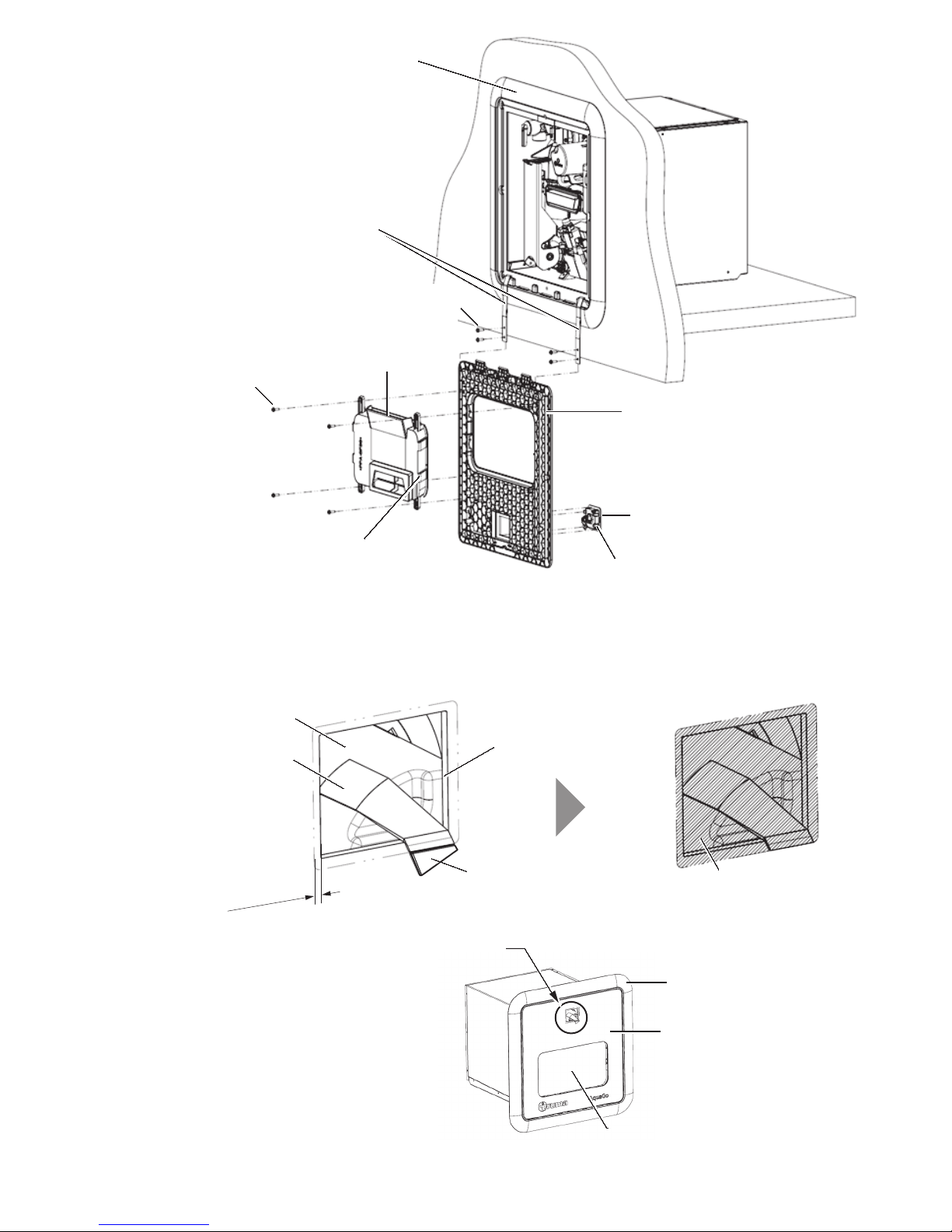
Cover plate
Screws (4 x)
Clips
from the back side
Detail A Detail A
Webbing
Screws (4 x)
Venting grid
Access door
Clips
Fig. 36
Flue fan
Turn lock opening
u
o
r
a
l
al
Tape
Remove
.
n
i
2
1
.
0
d
n
)
m
m
3
(
A
Turn lock
Masked area
Fig. 37
Cover plate
Outer surface
of Access door
Masking of the venting grid opening
43
Page 44

In case you encounter any problems,
please contact the Truma Service Center
at 855-558-7862 or one of our authorized
service partners. For details see
www.truma.net.
Please have the model number and serial
number (on water heater’s type plate)
handy when you call.
©
77000-00135 · 00 · 03/2016 ·
Manufacturing
Truma Gerätetechnik GmbH & Co. KG
Wernher-von-Braun-Straße 12
D - 85640 Putzbrunn
Germany
www.truma.com
Sales
Truma Corp
825 East Jackson Blvd.
Elkhart, IN 46516
USA
Toll Free 1-855-558-7862
Fax 1-574-538-2426
[email protected]
www.truma.net
 Loading...