

Page 1

EQUIPMENT DETAILS
79
EQUIPMENT DETAILS
Truma digital timer control (Carrera only) .................................................................................. 80
Truma Combination Boiler ....................................................................................................... 89
Truma Combi 4E ...................................................................................................................... 90
Dometic Absorption refrigerator ............................................................................................... 96
Waeco Fridge ........................................................................................................................ 111
Spinflo oven ........................................................................................................................... 117
SMEV minigrill ........................................................................................................................ 120
SMEV hotplate ...................................................................................................................... 121
Microwave oven .................................................................................................................... 123
Thetford cassette toilet .......................................................................................................... 125
Thetford C260 / C260S toilet ................................................................................................. 128
Window / Rollerblind advice ................................................................................................... 133
Roof lights ............................................................................................................................. 133
Seat swivel ............................................................................................................................ 135
Bunk bed safety .................................................................................................................... 135
Omnistep slide out step ......................................................................................................... 135
Omnistor awning ................................................................................................................... 136
Status 550 direction television and FM radio antenna ............................................................ 139
Avtex DVD ............................................................................................................................. 142
Avtex TV and aerial ................................................................................................................ 142
Care of laminate tops, tables, furniture and doors .................................................................. 142
Furniture doors ...................................................................................................................... 142
Table storage ......................................................................................................................... 142
Shower .................................................................................................................................. 143
Trigger Shower head ............................................................................................................. 143
TV inlet .................................................................................................................................. 143
Colour reference .................................................................................................................... 143
Page 2

EQUIPMENT DETAILS
80
Truma Digital Timer Control
(Carrera only)
Depending on the specification of your
motorhome, the Truma CP-Plus controller may
be fitted to control the operation of the Truma
Combi appliance.
Safety instructions
• The device may only be operated if it is in
perfect working order.
• Arrange for malfunctions to be rectified
immediately. Only rectify malfunctions
yourself, if the remedy is outlined in the
troubleshooting information in these
Operating Instructions.
• Do not repair or modify the device!
• Only allow the manufacturer or its customer
service to repair a faulty device.
Note: If the power supply to the systems is
interrupted for longer than 20 minutes, the
time and date need to be entered again.
Important note
If the power supply to the systems is
interrupted for longer than 20 minutes, the
time and date need to be entered again.
Intended use
The control panel Truma CP plus serves to
control and monitor a Combi heater and /
or a Truma air conditioning unit. The device
is designed for installation in caravans and
motor-caravans.
For clarity only the instructions relevant to
combi heating are included in this guide.
Instructions relevant to air conditioning should
be requested if an appropriate air conditioner
is fitted.
Display and control elements
2
3
5
4
8
6
7
9
1
1 - Display
2 - Status line
3 - Menu line (above)
4 - Menu line (below)
5 - Display of mains voltage 230 V
(shore power)
6 - Display timer
7 - Settings / values
8 - Control knob / push button
9 - Back button
The control knob / push button (8) is used to
select menus in the lines (3 + 4) and configure
the settings. These are shown via a display (1)
with a lighted background. Pressing the Back
button (9) takes the user back out of the menu
again.
Control knob / push button
The control knob / push button (8) is used to
select and change set values and parameters;
these can be saved by clicking the control
knob / push button. Selected menu items will
flash.
+
-
Turn to the right (+)
• Menu is paged from left
to right.
• Increase values.
TRUMA DIGITAL TIMER CONTROL
Page 3

EQUIPMENT DETAILS
81
Turn to the left (-)
• Menu is paged from right to left.
• Reduce values.
Clicking
• Accept (save) a selected
value.
• Select a menu item, change
to the setting level.
3 sec
Press (3 seconds)
• Main switch function
ON / OFF
Back button
Pressing the Back button (9) takes the user
back out of the menu again and discards the
settings. This means that the previous values
are retained.
Functions
The functions in the menu lines (3, 4) of the
control panel can be selected in any sequence.
The operating parameters are shown in the
status line (2) or the displays (5, 6).
Start / stand-by screen
After connecting the control panel to the
power supply, a start screen is shown after a
few seconds.
If no entry is made within a few minutes, the
standby screen is automatically shown again.
The display shows the time and current room
temperature alternately.
Switch on / return to setting level
• Press the control knob / push button for
longer than 3 seconds or the
• Back button.
The display shows the setting level. The first
symbol flashes.
Note: Previously set values / operating
parameters become active again after the
system is switched on.
Switch off
• Press the control knob / push button for
longer than 3 seconds.
Change the room temperature
• Use the control knob / push button to select
the symbol in menu line (3).
• Click to change to the setting level.
• Depending on the connected device, use the
control knob / push button to select between
the heater or air conditioning unit.
• Use the control knob / push button to select
the required temperature.
• Click the control knob / push button to
confirm the value.
2
3
a
d
b
c
Page 4

EQUIPMENT DETAILS
82
Heater
Settable temperature range 5 - 30 °C (1 °C
steps)
a = heater * – Heater is switched on.
Air conditioning unit (not normally fitted)
Settable temperature range 16 - 31 °C (1 °C
steps)
b = cool *
( Air conditioning unit is switched on)
c = auto
(Air conditioning unit is set to automatic)
d = hot
(Air conditioning unit is in heating mod.)
* This symbol will flash until the required room
temperature is reached.
Change the warm water level
• Use the control knob / push button to select
the symbol in menu line (3).
• Click to change to the setting level.
• Use the control knob / push button to select
the required level.
• Click the control knob / push button to
confirm the value.
2
3
a
b
c
d
a = Boiler *
(Warm water boiler is switched on)
b = 40°
(Warm water temperature 40 °C)
c = 60°
(Warm water temperature 60 °C)
d = boost *
(Targeted, fast heating of the content of the
boiler [boiler priority]. The water temperature
is kept at the higher level [around 62 °C] – Not
Combi Diesel. Once the water temperature is
reached, the room is heated again.)
* This symbol will flash until the required water
temperature is reached.
Select power type
• Use the control knob / push button to select
the symbol in menu line (3).
• Click to change to the setting level.
• Use the control knob / push button to select
the required power type.
• Click the control knob / push button to
confirm the value.
2
3
a
b
c
Symbol Operating mode Power type
a Gas Gas
b EL 1 Electro
b + c EL 2 Electro
a + b Mix 1* Gas + Electro
a + b + c Mix 2* Gas + Electro
* Mixed mode
TRUMA DIGITAL TIMER CONTROL
Page 5

EQUIPMENT DETAILS
83
Special aspects in the mixed mode
Interruption of the power supply 230 V
Combi Gas
The heater automatically switches to the gas
mode. As soon as the 230 V power supply is
reconnected, the heater automatically switches
back to the mixed mode.
Malfunction in the combustion process
(e.g. lack of fuel)
Combi Gas
The heater automatically switches to the
electro mode. If the heater should operate
in the mixed mode again, the cause of the
malfunction needs to be rectified. Switch the
heater off and on again on the control panel.
Select fan level
When the heater / air conditioning unit is
connected.
• Use the control knob / push button to select
the symbol in menu line (3).
• Click to change to the setting level.
• Use the control knob / push button to select
the required fan level.
• Click the control knob / push button to
confirm the value.
2
3
a b c d e f
Page 6

EQUIPMENT DETAILS
84
Symbol Operating mode Description
– Off Fan is switched off
a Vent
Circulating air, if no device is in operation. 9 speed levels can
be selected.
b Eco Low fan level
c Mid High fan level (only Combi Gas)
d High
Fast heating of the room. Available, if the difference between
the selected and current room temperature is >10 °C.
Set timer
• Use the control knob / push button to select
the symbol in menu line (4).
• Click to change to the setting level.
Note: If the timer is activated (ON), the timer
in the menu is shown as deactivated (OFF).
Enter start time
• Use the control knob / push button to set the
hours, then the minutes.
Enter end time point
• Use the control knob / push button to set the
hours, then the minutes.
Note: If the start / end times are exceeded
when entered, the operating parameters are
only taken into consideration when the next
start / end times are reached. Until then, the
operating parameters set outside the timer
remain valid.
Set the room temperature
• Click to change to the setting level.
• Use the control knob / push button to select
the required room temperature.
• Click the control knob / push button to
confirm the value.
Set the warm water level
• Click to change to the setting level.
• Use the control knob / push button to select
the required warm water level.
• Click the control knob / push button to
confirm the value.
TRUMA DIGITAL TIMER CONTROL
Page 7

EQUIPMENT DETAILS
85
Select power type
• Click to change to the setting level.
• Use the control knob / push button to select
the power type.
• Click the control knob / push button to
confirm the value.
Select fan level
• Click to change to the setting level.
• Use the control knob / push button to select
the required fan level.
• Click the control knob / push button to
confirm the value.
Activate the timer (ON)
• Click to change to the setting level.
• Use the control knob / push button to
activate the timer (ON)
• Click the control knob / push button to
confirm the value.
Note: The timer remains active, even for
several days, until it is deactivated (OFF).
Deactivate the timer (OFF)
• Click to change to the setting level.
• Use the control knob / push button to
deactivate the timer (OFF)
• Click the control knob / push button to
confirm the value.
Switch lighting on/off
Available if an air conditioning unit is connected
4
Set time
• The hour display flashes.
• Use the control knob / push button to set the
hours (24 h mode).
• After clicking the control knob / push button
again, the minute display will flash.
• Use the control knob / push button to set the
minutes.
• Click the control knob / push button to
confirm the value.
Page 8

EQUIPMENT DETAILS
86
Service menu
Query the index status of a
connected device
Change the background lighting of the
control panel
There are 5 background lighting levels to
choose from.
Change language
Select the required language from those
available (e.g. English, German, French, Italian).
Display mains voltage 230 V
The symbol indicates that 230 V mains voltage
(shore power) is available.
Warning
In the event of a warning, a warning symbol
appears to indicate that an operating
parameter has reached an undefined status.
In this case, the affected device continues
to run. As soon as the operating parameter
returns to the set range, this symbol will turn
off automatically.
Read out the warning code
• Use the control knob / push button to select
the symbol.
• Click the control knob / push button. The
current warning code is shown. The cause of
the warning can be identified and rectified via
the error list.
Cause rectified / return to setting level
• Click the control knob / push button.
Cause not rectified / return to setting level
• Press the Back button
Note: In this case, the warning is not
acknowledged on the control panel and the
warning symbol remains. The control panel
remains in the warning status. Devices connected to the control panel can be operated.
TRUMA DIGITAL TIMER CONTROL
Page 9

EQUIPMENT DETAILS
87
Malfunctions
In the case of a malfunction, the control
panel immediately jumps to the menu level
“malfunction” and shows the error code of the
malfunction:
Cause remedied / return to setting level
• Click the control knob / push button.
• The respective device is restarted.
If the cause is not remedied, the malfunction
will occur again and the control panel will jump
again to the menu level “malfunction”.
Cause not remedied / return to
setting level
• Press the Back button.
Note: In this case, the malfunction is not
acknowledged in the control panel and the
warning symbol remains on. The device
remains in the malfunction status. Other
devices connected to the control panel can
be operated.
Maintenance
This device is maintenance-free. Use a nonabrasive damp cloth to clean the front. If this
proves inadequate, use a neutral detergent.
Disposal
The device must be disposed of in compliance
with the administrative provisions of the
respective country in which it is used. The
national regulations and laws (in Germany
these are e.g. the End-of-Life Vehicle
Regulations) must be observed.
Page 10

EQUIPMENT DETAILS
88
Troubleshooting instructions
(Combi Gas heater)
Error code Cause Remedy
#17 • Summer mode with empty water
container
• Warm air outlet blocked
• Circulated air intake blocked
• Switch device off and allow to cool.
Fill boiler with water
• Check each of the outlet openings
• Remove the blockage from the
circulated air intake
#18 • Gas pressure regulator frozen
• Too much butane in the gas
cylinder
• Use the regulator heating (EisEx)
• Use propane (Butane is unsuitable
for heating, especially at temperatures below 10
o
C
#21 • Room temperature sensor or
cable faulty
• Please contact the Truma Service
#24 • Potential under-voltage battery
voltage too low <10.4V
• Charge battery
#29 • Heating element for FrostControl
has a short circuit
• Disconnect the heating element
plug on the electronic control unit.
Replace heating element
#41 • Electronics are blocked • Please contact the Truma Service
#42 • Window above the cowl is open
(window switch)
• Close the window
#43 • Over-voltage > 16.4V • Check the battery voltage and volt-
age sources eg. the charger
#44 • Under-voltage battery voltage too
low < 10.0V
• Charge battery. Replace any
old batteries
#45 • No 230V operating voltage
• Faulty 230V fuse
• Overheating protection has
triggered
• Reconnect the operating
voltage 230V
• Replace the 230V fuse
• Reset the overheating protection.
Allow the heating to cool down,
remove the connection cover and
press the reset button
#112 • Gas cylinder or quick-acting valve
in the gas line closed
• Check the gas supply and open
the valves
#212 • Combustion air intake or exhaust
outlet closed
• Check the openings for soiling
(snow, ice, leaves etc) and remove
#255 • No connection between the heater
and the control panel
• Control panel cable faulty
• Please contact the Truma Service
If these steps do not rectify the malfunction,
please contact the Truma Service.
TRUMA DIGITAL TIMER CONTROL
Page 11

EQUIPMENT DETAILS
89
The instructions covering fitted equipment
to your vehicle were correct at the time
of going to print. Owners handbooks are
updated annually and we take great care to
try and ensure their accuracy. However,
Swift Group Limited cannot accept
responsibility for any changes that may
be made in specification or operating
instructions to the equipment described in
this section after the time of going to press.
Every care is taken to ensure that the
information provided in this handbook is
correct and easy to understand.
Separate manufacturers’ leaflets on many
of the components are also included in the
Owner’s Pack provided with this vehicle
and we recommend that you compare
the instructions in the handbook with
the component manufacturers literature,
to ensure the information provided is as
accurate as possible.
If you are in any doubt as to how to operate
the equipment in your vehicle, please
contact the component manufacturer’s
service department on the telephone
number shown on their component leaflet.
If you remain in any doubt, please contact
customer care service department
on 01482 875740.
Equipment Specification
For details on type of equipment fitted in your
vehicle, please refer to the Sales Brochure or
Dealer.
! WARNING: To maximise the use and
life of all fitted equipment in your vehicle
it is essential that any accompanying
manufacturers’ literature is read fully. All
recommended maintenance and preparation
procedures should be followed. The
information provided in this handbook is
only intended as a guide. If in any doubt
consult your manufacturer appointed dealer,
particularly before attempting to install
EXTRA EQUIPMENT.
Note: In the interest of safety, replacement
parts for an appliance shall conform to the
appliance manufacturer’s specifications
and should be fitted by them or their
authorised agent.
Truma Combination Boiler
The Truma Combination Boiler has been
designed to run on gas or electric power and
the optimum performance is obtained when
used in dual fuel mode, that is running on
gas and electric at the same time.
Running in dual fuel mode has the following
benefits:
• Fastest possible heat up time, the 2KW
gas burner combines with a 1.8KW electric
element to provide 3.8KW of energy to heat
your hot water and warm your caravan.
• The intelligent heat management system
automatically senses when the water and
room are nearing the required temperature
and then automatically turns off your gas
burner and operates solely electric power,
conserving your gas.
• As hot water is used or the room cools the
Truma combination heater will continue to
operate on electric only until a point where
the demands necessitate that additional
gas power is required. An example for
such a demand could be for instance if the
exterior door was left open and the room
temperature dropped by 10 degrees in the
space of a few minutes, in this case the
intelligent heat management system would
decide that the best way to get the room
back to the required temperature would be
to use both gas and electric at the same
time.
Operating the Truma Combination system on
electric or gas only will result in longer heat up
times for hot water and the room temperature
n comparison to operating on dual fuel.
Operating on electric only may not in all cases
maintain a comfortable room temperature
especially in colder conditions.
TRUMA COMBI BOILER
Page 12

EQUIPMENT DETAILS
90
The intelligent heat management system
operation in dual fuel mode and allow the
Truma Combination boiler to prioritize the
electric power source over your gas, which all
conserve your gas supply.
Truma Combi 4E
1 Control panel
2 Power selector switch
3 Optional timer
4 Room temperature sensor
5 Cold water connection
6 Hot water connection
7 Gas connection
8 Hot air outlets
9 Recirculated air intake
10 Waste gas discharge
11 Combustion air infeed
12 Electronic control unit
13 Water container (10 litres)
14 Burner
15 Heat exchanger
16 Power electronics
17 Heating elements 230 V
18 Overheating switch 230 V
Function description
The liquid gas heater ‘Truma Combi’ is a
warm-air heater with integrated hot water
boiler (10 litre volume). The burner operates
fan-supported, which ensures trouble-free
function even when on the move.
In winter operation the heater can be used to
heat the room and simultaneously warm water.
If only warm water is required, select
summer operation.
• In summer operation, the water contents are
heated in the smallest burner stage. Once
the water temperature is reached, the burner
switches off.
• In winter operation, the unit automatically
selects the required power setting according
to the temperature difference between the
temperature set on the control panel and the
current room temperature. When the boiler
is filled, the water is automatically heated as
well. The water temperature depends on the
selected operational mode and the heater
output.
At a temperature of approximately 3° C at the
automatic FrostControl safety/drain valve, the
valve will open and drain the boiler.
The unit is not suitable for use as a flow heater.
Safety instructions
If the gas system is leaking or if there is a
smell of gas:
• extinguish all open flames
• open windows and door
• close all quick-acting valves and gas
cylinders
• do not smoke
• do not activate any electric switches
• ask an expert to inspect the entire system!
Repairs may only be carried out by an
expert!
Any modifications to the unit, including
accessories, exhaust duct, and cowl, or the
use of spare parts and accessories that are
important to the operation of the system
TRUMA COMBI 4E
Page 13

EQUIPMENT DETAILS
91
that are not original Truma parts and failure
to follow the installation and operating
instructions will cancel the warranty and
indemnify Truma from any liability claims. It also
becomes illegal to use the appliance, and in
some countries this even makes it illegal to use
the vehicle.
The gas supply’s operating pressure (30 mbar)
must be the same as the unit’s operating
pressure (see type plate).
The vehicle owner is always responsible for
arranging the inspection.
Liquid gas equipment may not be used when
refueling, in multi-storey car parks, in garages,
or on ferries.
During the initial operation of a brand new
appliance (or after it has not been used for
some time), a slight amount of fumes and
smell may be noticed for a short while. It is a
good idea to heat the device up several times
in summer operation (60° C) and to make sure
that the area is well ventilated.
Heat-sensitive objects such as spray cans
or flammable liquids may not be stored in
the same compartment where the heater is
installed because, under certain conditions,
this area may be subject to elevated
temperatures.
Only pressure regulating equipment that
complies with EN 12864 (in vehicles) with fixed
output pressure of 30 mbar may be used for
the gas system. The flow rate of the pressure
control device must correspond to at least the
maximum consumption of all devices installed
by the system manufacturer.
For vehicles, we recommend Truma’s
SecuMotion gas pressure regulator; for the
two-cylinder gas system we also recommend
the Truma DuoComfort changeover valve.
At temperatures below 5° C, the gas pressure
regulator or the changeover valve should be
used with EisEx regulator heating.
Controller connecting hoses that meet national
regulations must always be used in the
respective country for which the equipment
is destined. These hoses must be checked
regularly for brittleness. Winter-proof special
hoses must always be used if the equipment is
operated during the winter.
Pressure regulating equipment and hoses
must be replaced with new ones no more
than 10 years after the date of manufacture
(every 8 years if used commercially). This is the
responsibility of the operator.
Do not use the boiler water as drinking
water!
Important operating notes
If the cowl has been placed near or directly
beneath an opening window, the device
must be equipped with an automatic shut-off
device in order to prevent operation with the
window open.
The integrity and tight fit of the exhaust gas
double duct must be checked regularly,
particularly at the end of long trips. Also check
the mounting of the appliance and the cowl.
Following a blow-back (misfire) always have
the exhaust gas system checked by an expert!
Always keep the cowl for the exhaust duct and
combustion air intake free of contamination
(slush, ice, leaves etc.). The warm air outlets
and the openings for circulation air return must
be unobstructed so the unit will not overheat.
The integrated temperature limiter blocks the
gas supply when the unit becomes too hot.
! WARNING: Care should be taken
to ensure adequate ventilation of the flue
at all times. It is inadvisable to inhale
exhaust fumes.
Directive 2004/78/EC stipulates that a safety
shut-off device is required if motor homes are
being heated while driving.
The Truma SecuMotion gas pressure regulator
meets this requirement.
Note: If the Truma SecuMotion gas pressure
regulator is not installed, the gas cylinder
must be closed while driving and warning
signs must be in place in the gas cylinder
protection box and near the control panel.
The safety shut-off device is also
recommended for safety reasons if
motorhomes are being heated while driving.
Page 14

EQUIPMENT DETAILS
92
Standard Operating Instructions
Always observe the operating instructions and
‘Important operating notes’ prior to starting!
The vehicle owner is responsible for the
correct operation of the appliance.
The installer or vehicle owner must apply the
yellow sticker with the warning information,
which is enclosed with the appliance, to a
place in the vehicle where it is clearly visible to
all users (e.g. on the wardrobe door)!
Ask Truma to send you stickers, if necessary.
Before using for the first time, it is essential
to flush the entire water supply through with
clean warm water. If the heater is not being
used, always drain the water contents if there
is a risk of frost. There shall be no claims under
guarantee for damage caused by frost!
Gas operation (heating and hot water)
a. Rotary switch for room temperature (1 – 5)
b. green LED lit ‘Operation’ green LED blinking
‘after-running’ is active in order to reduce
the unit’s temperature
c. Summer operation (water temperature
40° C or 60° C)
d. Winter operation (heating without water
temperature monitoring or with drained
water system)
e. Winter operation (heating with water
temperature monitoring)
f. Rotary ‘Off’ switch
g. Yellow LED lit ‘Boiler heat-up phase’
h. Red LED lit, red LED blinking ‘Failure’
The LEDs are visible only when the unit is
switched on.
Room thermostat
i. Room temperature sensor
To measure the room temperature, an external
room temperature sensor (i) is located in the
vehicle. The location of the sensor is
determined individually by the vehicle
manufacturer, depending on the vehicle type;
consult the operating instructions for your
vehicle for further details.
The thermostat setting on the control panel
(1 – 5) must be determined individually
depending on the heating requirement and
the type of vehicle. For an average room
temperature of about 23° C, we recommend a
thermostat setting of about 4.
Taking into operation
Heating operation is basically possible without
restriction with or without water content.
Check to make sure the cowl is unobstructed.
Be sure to remove any covers that may
be present.
Turn on gas cylinder and open quick-acting
valve in the gas supply line.
Summer operation (boiler operation only)
Move the rotary switch on the control panel to
position (c – summer operation) 40° C or 60°
C. The green (b) and yellow (g) LEDs light up.
After reaching the set water temperature
(40° C or 60° C), the burner will switch off and
the yellow LED (g) will be extinguished.
TRUMA COMBI 4E
Page 15

EQUIPMENT DETAILS
93
Winter operation
Heating with water temperature
monitoring
Set the rotary switch to the operational setting
‘e’. Set the rotary switch (a) to the desired
thermostat setting (1 – 5). The green LED (b)
for operation is lit and simultaneously indicates
the position of the selected room temperature.
The yellow LED (g) indicates the water’s heatup phase.
The unit automatically selects the required
power level according to the temperature
difference between the setting on the control
panel and the current room temperature.
Once the room temperature set on the control
panel has been reached, the burner switches
back to the lowest stage, and heats the water
content to 60° C. The yellow LED (g) will be
extinguished after the water temperature is
reached.
Heating without water
temperature monitoring
Set the rotary switch to the operational setting
‘d’. Turn the rotary switch (a) to the desired
thermostat setting (1 – 5). The green LED (b)
for operation is lit and simultaneously indicates
the position of the selected room temperature.
The yellow LED (g – water’s heat-up phase)
will be lit only when the water temperature is
below 5° C!
The unit automatically selects the required
power level according to the temperature
difference between the setting on the control
panel and the current room temperature.
After reaching the room temperature set on
the control panel, the burner will switch off.
The warm-air fan will continue to run at a low
speed as long as the blow-out temperature (on
the unit) is higher than 40° C.
If the boiler is filled, the water will automatically
be heated at the same time. The water
temperature is then dependent on the heating
output being given off, and the duration of
heating required to reach the desired room
temperature.
Heating with drained water system
Set the rotary switch to the operational setting
‘d’. Turn the rotary switch (a) to the desired
thermostat setting (1 – 5). The green LED (b)
for operation is lit and simultaneously indicates
the position of the selected room temperature.
The yellow LED (g) will be lit only when the
temperature of the unit is below 5° C!
The unit automatically selects the required
power level according to the temperature
difference between the setting on the control
panel and the current room temperature. After
reaching the room temperature set on the
control panel, the burner will switch off.
Switching off
Use the rotary switch to switch off heater
(position f). The green LED (b) goes off.
If the green LED (b) blinks after switching off,
then the unit’s after-running is active in order
to reduce the unit’s temperature. This will end
after a few minutes and the green LED (b) will
go off.
! WARNING: Always drain water contents
if there is a risk of frost!
If the appliance is not to be used for a
prolonged period, close the quick-acting valve
in the gas supply line and turn off the gas
cylinder.
Red LED ‘Failure’
The red LED (h) will be lit if there is a failure.
Please consult the Trouble-Shooting list for
possible causes.
Reset (failure reset) the unit by switching it off
and back on.
If the window switch is opened, the heating
unit will stop operating and the red LED (h) will
blink. Once the window switch is closed, the
heating unit will continue operation and the
green LED (b) will be lit continuously.
Page 16

EQUIPMENT DETAILS
94
Filling the water heater
Check if the rotary switch for the drain valve
(FrostControl) is set to ‘Operation’, meaning
that it is parallel to the water connection
and engaged.
When the temperature at FrostControl is below
about 7° C, first switch on the heater to warm
the installation compartment and FrostControl.
After several minutes, when the temperature at
FrostControl is above 7° C, the drain valve can
be closed.
Close the drain valve by pushing the push
button until it engages. Switch on power for
water pump (main switch or pump switch).
Open hot water taps in kitchen and bathroom,
(set preselecting mixing taps or single-lever fittings
to ‘hot’). Leave the fittings open for as long as it
takes for the boiler to displace the air and fill up,
and the water to flow without interruption.
If just the cold water system is being operated,
without using the water heater, the heater tank
also fills up with water. To avoid frost damage,
the boiler must be drained through the drain
valve, even if it was not operated. As an
alternative, two shutoff valves, resistant to hot
water, can be fitted in front of the cold and hot
water connection.
When connecting to a central water supply
(rural or city mains), a pressure reduction valve
must always be installed to prevent pressures
above 2.8 bar from developing in the water
heater.
Draining the water heater
Switch off power to water pump (main or
pump switch).
Open hot water taps in kitchen and bathroom.
Turn the yellow boiler drain valve to the up
position to dump the water.
The boiler is now drained directly to the
outside via the drain valve. Place a bucket
beneath the outlet to check whether the
water content has completely drained away
(10 litres). There shall be no claims under
guarantee for damage caused by frost!
Maintenance
Only original Truma parts may be used for
maintenance and repair work!
The water container used is made of stainless
steel, which is foodstuff-compatible.
Use wine vinegar for descaling the water heater,
this being introduced into the appliance via the
water supply. Allow the product to react and
then thoroughly flush out the appliance with
plenty of fresh water. For sterilization purposes
we recommend ‘Certisil-Argento’; other
products (especially those containing chlorine)
are unsuitable and may damage the unit.
To avoid microorganisms colonizing the water
in the boiler, heat the water to 70° C at regular
intervals (at least once per year).
Move the rotary switch on the control panel
to position (c – summer operation) 60° C. The
green (b) and yellow (g) LEDs light up.
Once the water in the boiler has reached a
temperature of 60° C, the burner will switch
off and the yellow LED (g) will go out. The unit
must stay switched on for at least 30 minutes
and no warm water may be removed. The
residual heat in the heat exchanger will heat
the water up to 70° C.
Fuses
The unit’s fuse is located on the electronics
under the connection cover. Replace the unit’s
fuse only with an identical fuse.
Device fuse: 10 A – slow – (T 10 A)
TRUMA COMBI 4E
Page 17

EQUIPMENT DETAILS
95
Disposal
The liquid gas heater must be disposed in
accordance with the administrative stipulations
of the respective country in which it is used.
National regulations and laws (in Germany,
for example, the Altfahrzeug-Verordnung (old
vehicle directive) must be observed.
In other countries, the relevant regulations
must be observed.
Technical data
Determined in accordance with EN 624 or
Truma test conditions
Device category: I
3 b/p
in accordance with
EN 437
Type of gas: Liquid gas (propane/butane)
Operating pressure: 30mbar (see type plate)
Water contents: 10 litres
Heating up time from approx 15°C to
approx 60°C
Boiler approx 20 minutes (measured according
to EN 15033) Heater + boiler approx 80 min
Pump pressure: max 2.8 bar
System pressure: Max 4.5 bar
Rated thermal ouput
(automatic output levels)
Gas operation
Combi 4 E: 2000 / 4000 W
Electrical operation
Combi 4 E 900W / 1800 W
Mixed operation (gas and electrical)
Combi 4 E: max 3800 W
Gas consumption
Combi 4: 160-320 g/h
Readiness-heat power requirement
Combi 4 E
Gas operation 5.2g/h
Air delivery volume (gree-blowing without
hot air pipe)
Combi 4: with 3 hot air outlets max 249 m3/h
with 4 hot air outlets max 287 m3/h
Current input at 12 V
Heater + boiler
Combi 4 E: Short term max 5.6A
(average power consumption 1.1A)
Heating up of boiler: 0.4 A
Stand by: 0.001 A
Heating element FrostControl (optional):
maximum 0.4 A
Current input of 230V
3.9 A (900 W) or 7.8 A (1800 W)
Weight (not containing water):
Heater unit: 15.1kg
Heater unit with peripheral devices: 15.6kg
Troubleshooting
For troubleshooting a fault please refer to page 9
of the Truma Combi 4E Operator Manual.
Truma Heating System and Air Flow
The Swift Group undertakes considerable
testing of our products in cold chambers to
ensure they are usable in cold temperatures.
During this testing, the air flow on the blown
air outlets is defined and set by us. In some
cases, customers may wish to alter this setup
to achieve a different heating pattern (i.e. more
hot air to the rear of the vehicle or vice-versa)
and this can be achieved by placing restrictors
in the blown air system.
Customers should seek the advice of Truma or
their Dealer on how to do this.
Page 18

EQUIPMENT DETAILS
96
Dometic absorption refrigerator
Guide to these operating instructions
Before you start using the refrigerator,please
read the operating instructions carefully.
These instructions provide you with the
necessary guidance for the proper use of your
refrigerator. Observe in particular the safety
instructions. Observation of the instructions
and handling recommendations is important
for dealing with the refrigerator safely and for
protecting you from injury and the refrigerator
from damage. You must understand what you
have read before you carry out a task.
Keep these instructions in a safe place close
to the refrigerator so they may be referred to
at any time.
Copyright protection
The information, texts and illustrations in these
instructions are copyright protected and are
subject to industrial property rights.
No part of these instructions may be
reproduced, copied or utilised in any other
way without written authorisation by Dometic
GmbH, Siegen.
Warranty
Warranty arrangements are in accordance
with EC Directive 44/1999/CE and the
normal conditions applicable for the country
concerned.
For warranty or other maintenance, please
contact our customer services department.
Any damage due to improper use is not
covered by the warranty. The warranty does
not cover any modifications to the appliance
or the use of non-original Dometic parts. The
warranty does not apply if the installation and
operating instructions are not adhered to and
no liability shall be entertained.
Limitation of liability
All information and guidance in these operating
instructions were prepared after taking into
consideration the applicable standards and
regulations as well as the current state of the
art. Dometic reserves the right to make changes
at any time which are deemed to be in the
interest of improving the product and safety.
Dometic will assume no liability for damage in
the case of :
• Non-observation of the operating instructions
• Application not in accordance with the
regulations or provisions
• Use of non-original spare parts
• Modifications and interferences to the
appliance
• Effect of environmental influences, such as
- temperature fluctuations
- humidity
Customer services
Dometic offers a pan-European customer
service network. Find your authorised
customer service centre by calling the
phone number indicated in the EuroService
Network book, EuroService Network - which
accompanies every refrigerator. You can also
obtain the address information of the nearest
customer service from www.dometic.com.
When contacting Dometic Customer Services,
please state the model, product number and
serial number together with the MLC code,
if applicable. You will find this information on
the rating plate inside the refrigerator. We
recommend that you note this data in the
field provided on the front page of this
operation manual.
Spare parts
Parts can be ordered throughout Europe from
our customer services. Always give the model
and product number when you contact the
customer service! You will find this information
on the rating plate inside the refrigerator.
DOMETIC ABSORPTION REFRIGERATOR
Page 19

EQUIPMENT DETAILS
97
Note: Refrigerators manufactured by
Dometic GmbH are free of CFC/HCFC
and HFC. Ammonia (a natural compound
of hydrogen and nitrogen) is used in the
cooling unit as a coolant. Non-ozonehazardous cyclopentane is used as a
propellant for manufacturing PU foam
insulation.
In order to ensure that the recyclable packaging
materials are re-used, they should be sent to
the customary local collection system.
The appliance should be transferred to a
suitable waste disposal company that will
ensure re-use of the recyclable components
and proper disposal of the rest. For ecofriendly draining of the coolant from all
absorber refrigeration units, a suitable disposal
plant should be used.
Energy-saving tips
• At an average ambient temperature of 25°C,
it is sufficient to operate the refrigerator at
middle thermostat setting.
• Where possible, always store precooled
products.
• Do not expose the refrigerator to direct
sunlight.
• Ensure that air circulation of the cooling unit
is not obstructed.
• Defrosting at regular intervals saves energy
(see “Defrosting”). Open the refrigerator
door only for a short period of time when
removing products.
• Run the refrigerator for about 12 hours
before filling it.
Safety instructions
Application according to regulations
This refrigerator is designed for installation
in recreation vehicles such as caravans
or motorhomes. The appliance has been
type approval tested for this application in
accordance with the EC Gas Directive.
The refrigerator is to be used solely for
storing foodstuffs.
! WARNING: The refrigerator is not suitable
for the proper storage of medication. Please
observe in addition the instructions in the
medication package inserts.
User’s responsibility
Anyone operating the refrigerator must be
familiar with the safe handling and understand
the advice in these operating instructions.
Children may only operate the appliance,
if they have been made aware of how to
operate the refrigerator safely and the dangers
attending incorrect operation.
Protection of children when disposing of
the equipment
! WARNING: When disposing of the
refrigerator, detach all refrigerator doors and
leave the storage racks in the refrigerator.
In this way inadvertent entrapment and
suffocation is prevented.
Working upon and checking
the refrigerator
! WARNING: Work on gas equipment,
exhaust system and electrical facilities must
be carried out by authorised personnel
only. Substantial damage to property and
/ or injury to persons can arise through
unprofessional procedures.
! WARNING: Never use an unshielded
flame to check gas bearing parts and pipes
for leakage!
There is a danger of fire or explosion.
Page 20

EQUIPMENT DETAILS
98
! WARNING: Never open the absorber
cooling unit! It is under high pressure.
There is a danger of injury.
Information on coolant
Ammonia is used as a coolant. This is a natural
compound also used in household cleaning
agents (1 litre of Salmiak cleaner contains up
to 200g of ammonia - about twice as much as
is used in the refrigerator). Sodium chromate is
used for corrosion protection (1.8% by weight
of the solvent).
In the event of leakage (easily identifiable from
the strong odour), proceed as follows:
• Switch off the appliance.
• Air the room thoroughly.
• Inform authorised customer services.
Note: For your safety it was ascertained
in an expert’s report that no impairment
of health exists when the coolant is
discharged.
Operating the refrigerator with gas
It is imperative that the operating pressure
corresponds to the data specified on the rating
plate of the appliance. Compare the operating
pressure of the rating plate with the data
specified on the pressure reducing valve of the
liquid gas cylinder.
! WARNING: Operating the appliance
with gas is not permitted
• At petrol stations
• On ferry boats
• While transporting the caravan /
motorhome by a transporter or
breakdown vehicle.
There is danger of fire! Leave the equipment
switched off.
Safety instructions when
storing foodstuffs
Instructions for storing food in
a refrigerator:
No refrigerator of any kind can improve the
quality of the food; refrigerators can only
maintain the food’s quality for a short duration
as from the time of storing it.
Please observe the following particular
conditions for storing food in a refrigerator that
is built into a vehicle:
• A change in the climatic conditions such as
temperature fluctuations
• High temperatures inside the vehicle when
it is closed and parked in direct sunlight
(temperatures are possible up to 50°C)
• Use of the refrigerator during travel with the
power supply of 12V DC
• A refrigerator built in behind a window and
exposed to direct sunlight
• Storing the products too soon, i.e. shortly
after starting up the appliance for use
Under these particular conditions the
refrigerator cannot guarantee reaching the
temperature needed for perishables.
Perishables include all products with a
stipulated use-by date and a minimum storage
temperature of +4°C or less, especially for
meat, poultry, fish, sausages, pre-packed
foods.
• Pack raw and cooked foods separately
(e.g. in containers, aluminium foil, etc.).
• Only remove the outside packaging of single
packs if all the necessary information, e.g.
the use-by date, can also be read on the
single packs.
• Do not leave cooled goods outside the
refrigerator for too long.
• Place the foods with the next use-by date at
the front, accordingly.
• Pack away any left-over food and eat at the
first opportunity.
DOMETIC ABSORPTION REFRIGERATOR
Page 21

EQUIPMENT DETAILS
99
• Wash your hands before and after handling
any food.
• Regularly clean the inside of the refrigerator.
Please observe the instructions and
information regarding the use-by date on the
outside packaging of the food.
Please observe section “Cleaning” of this
instruction.
Refrigerator rating plate
The rating plate is to be found on the inside of
the refrigerator. It contains all important details
of the refrigerator. You can read off from this
the model identification, the product number
and the serial number. You will need these
details whenever you contact the customer
service centre or when ordering spare parts.
1. Model Number
2. Product Number
3. Serial Number
4. Electrical rating details
5. Gas pressure
Note: Dometic refrigerators are equipped
for a connection pressure of 30 mbar. For
connection to a 50 mbar gas system, use
Truma VDR 50/30 medium pressure controller.
Page 22
EQUIPMENT DETAILS
100
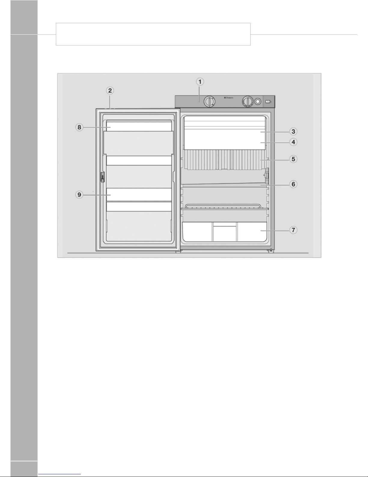
Description of refrigerator
1. Operating controls
2. Door locking button
3. Freezer compartment (removable)
4. Insertable grid shelf (available as option,
to be used when freezer compartment is
removed)
5. Post-evaporator for cooling compartment
6. Condensation water drain channel
7. Vegetable bin
8. Upper door shelf with flap, egg shelf
available as option may be inserted
9. Lower door shelf with bottle holders
DOMETIC ABSORPTION REFRIGERATOR
Page 23
EQUIPMENT DETAILS
101
Refrigerator operation
The refrigerator is equipped to operate on
three power modes:
• Mains voltage (230V AC)
• Direct-current voltage (12V DC)
• Gas (liquid gas propane/butane)
Select the desired power mode by the energy
selector switch (battery igniter type models)
or the MODE button (MES, AES). Appliances
with automatic energy selection (AES) are
additionally provided with “automatic mode”
function. The AES system automatically
selects the best energy source for each
particular situation.
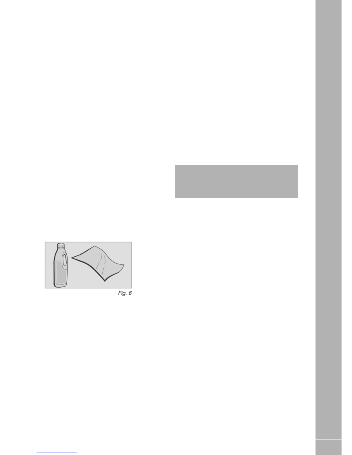
Cleaning
Before starting up the refrigerator, it is
recommended that you clean it inside and
repeat this at regular intervals.
Use a soft cloth and lukewarm water with a
mild detergent. Then wipe out the appliance
with clean water and dry thoroughly.
To avoid material alterations, do not use soap or
hard, abrasive or soda-based cleaning agents.
Do not allow the door seal to come into
contact with oil or grease.
Maintenance
• In compliance with the applicable
regulations, please note that the gas unit
and the connected ventilation ducts must be
checked by authorised technical personnel
after first use and after every other year for
compliance with the European Standard EN
1949. A test certificate has to be issued. It is
the user’s responsibility to arrange this test.
• The gas burner must be inspected and
cleaned as necessary at least once a year.
When using liquefied petroleum gas (tank
or refill cylinders) the maintenance interval is
reduced to half-yearly or quarterly. Keep the
evidence of maintenance work carried out on
your refrigerator.
• Work on gas and electrical equipment shall
be carried out by qualified personnel only.
It is recommended that this is carried out by an
authorised customer services department.
We recommend maintenance following an
extended shutdown of the vehicle.
Note: We recommend maintenance
following an extended shutdown of the
vehicle. Please contact our customer
services.
The cooling unit's performance is influenced
by ambient temperatures. Please select the
medium setting for ambient temperatures
between +15°C and +25°C (refer to Setting of
cooling compartment temperature). The unit
operates within its optimum performance range.
Dometic refrigerators work according to the
absorption principle. For physical reasons,
an absorption system responds slowly to
changes made by the thermostat controller,
by loss of cooling energy through opening the
door or during storing food. The devices meet
the cooling performance requirements of the
Climatic Class SN acc. to EN/ISO 7371 in the
temperature range of +10°C to +32°C ambient
temperature.
For temperatures below +10°C, winter
covers should be installed. For ambient
temperatures exceeding +32°C for a
longer period of time, it is recommended
installing Dometic additional fan (item no.
241 2985 -00 ).
Page 24

EQUIPMENT DETAILS
102
Manual energy selection /
automatic ignition (RM 8xx1) MES
Fig. 8
1 2
3
4 6
7 8
1. Power ON/OFF switch
2. Energy selector button 230V ~
3. Energy selector button GAS
4. Energy selector button 12V =
6. Temperature level selection
7. Temperature level display
8. Indicator LED failure /
Reset button GAS FAILURE
Switching ON/OFF
• Switch ON by pressing button (1), 2s
• Switch OFF by pressing button (1), > 2s
230V AC operation
• Select “Mains voltage” by pressing
button (2)
• Set temperature step by pressing button (6)
12V DC operation (vehicle’s battery)
• Select “Battery voltage” by pressing
button (4)
• Set temperature step by pressing button (6)
Gas operation
• Select “Gas” by pressing button (3)
• Set temperature step by pressing button (6)
Electrical operation
To start the refrigerator, press button (1) for 2
seconds.
The refrigerator starts with the last selected
type of energy.
230V operation :
Press button (2) :
12V operation :
Press button (4) :
Gas operation
Fig. 17
3
Gas operation :
Press button (3) :
The ignition process is activated automatically
by means of an automatic igniter.
Note: The flame extinguishes after
reaching the preset cooling compartment
temperature and ignites again if the cooling
compartment temperature increases again.
If the flame is not lit after the first ignition
attempt, the automatic igniter repeats the
ignition twice (duration 30 s) at time intervals
of 2 minutes. If the flame is not lit afterwards,
a fault is indicated.
DOMETIC ABSORPTION REFRIGERATOR
Page 25
EQUIPMENT DETAILS
103
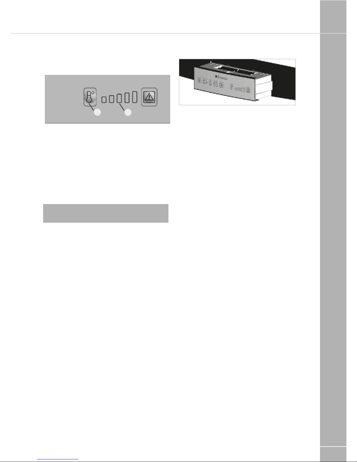
Setting of cooling compartment
temperature
Fig. 18
6
7
Select the desired cooling compartment
temperature by pressing button (6) .
The LED display (7) of the selected
temperature setting is illuminated.
The scale starts with MIN position at the left
LED position (small bar = highest temperature)
and climbs up to MAX position at the right
LED position (large bar = lowest temperature).
Note: The temperature levels do not relate
to absolute temperature values.
Additional features (MES / AES)
• The brightness of the display reduces after a
few seconds if no other buttons are pressed.
The indicator lights again if a button is
pressed. Press the button again to activate
the required function.
• Failures are indicated by flashing of the failure
indicator LED.
• Should the door be kept open for too long
(more than 2 minutes), an acoustic signal is
initiated (pulsing whistle tone).
• Should the electronic control detect any
failure, an acoustic signal will sound (pulsing
whistle tone). At the same time the display
starts flashing (for trouble-shooting, please
refer to page 104).
Gas operation with internal
batteries (optional)
An optional battery compartment in the
electronics case for internal (self-contained)
power supply of the electronics is available
for the model variants RM 8xx1 and RM 8xx5
(appliances with electronics).
Fig. 21
Battery compartment
Load the battery compartment with batteries
(8 x AA 1.5 V) before operating the refrigerator.
All operating modes can be selected while the
on-board 12 V DC power supply is active. The
internal voltage is disconnected.
If the on-board 12 V DC power supply is not
present or there is an interruption of the mains
power supply during operation, the electronics
automatically switch to the internal (battery)
power supply.
The refrigerator can now only be operated in
the gas mode.
All LED indicators except the GAS LED are
not lit during operation with internal batteries.
The GAS LED flashes every 15 seconds. If a
button is pressed, the temperature level LEDs
(7) also light.
If the battery voltage is too low, an acoustic
signal (whistle tone) sounds every 15 seconds.
Then replace the batteries in the battery
compartment.
Inserting / changing the batteries
• Switch off the refrigerator, as described in
section 4.17 Shutting of the refrigerator.
Page 26
EQUIPMENT DETAILS
104
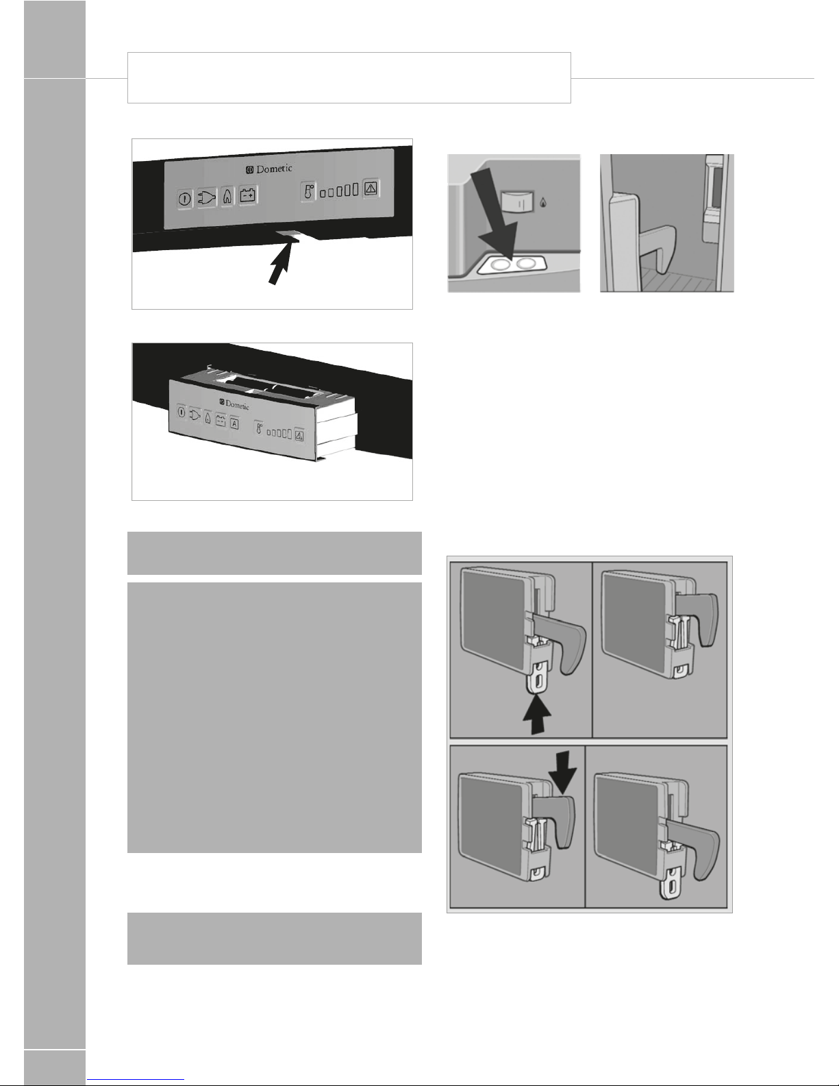
Fig. 23
Fig. 22
Opening battery compartment
press
pull out
Note: Batteries (8 x AA 1.5V) are not
included!
! WARNING:
• Observe the correct polarity !
• Do not connect non-rechargeable batteries to a charger.
• Remove rechargeable batteries from the
battery compartment before charging.
• Avoid short circuits on the contacts in the
battery compartment!
• Remove discharged batteries.
• Remove the batteries from the battery
compartment if the refrigerator will not be
used for a long time.
• Do not mix different types of batteries.
Door locking
! WARNING: As a basic rule, shut and lock
the refrigerator before you start your journey!
Mechanical door lock
Open the door by pressing the locking button
and pull open. Shut the door again by pushing
it to close. The snapping into the lock can be
heard. While the vehicle is parked, the locking
hook may be fixed to facilitate opening of the
door.
Fastening and releasing the door lock
hook when parking the vehicle
If the vehicle is parked for a longer period
of time, the locking hook may be clamped
by means of a lockbar. The door may now
be opened by just pulling it without need of
pressing the locking button.
DOMETIC ABSORPTION REFRIGERATOR
Page 27
EQUIPMENT DETAILS
105
Lighting
If the door is open for more than 2 minutes,
the sensor-controlled interior lighting is
automatically cut off (except for models with
battery igniter).
Note: Please contact the authorized
Dometic Service if a failure occurs.
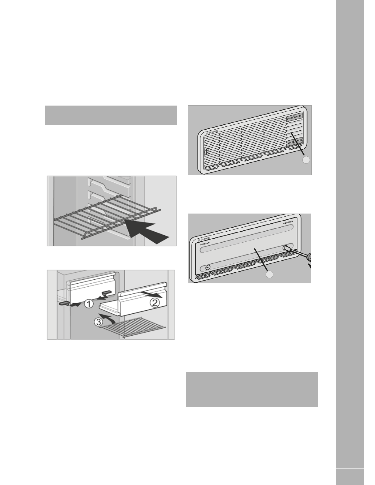
Positioning the storage racks
The storage racks may be pulled out by
smoothly lifting them and may be positioned
as desired.
Removable freezer compartment
(where applicable)
To enlarge the cooling compartment, just
remove the freezer compartment.
1. Unlock the freezer compartment on both
sides.
2. Pull the freezer compartment out.
Store the freezer compartment safely in order
to prevent damage.
Once the freezer compartment is removed, an
additional storage rack (3.) may be installed.
The storage rack is a piece of extra equipment
and may be obtained by Dometic.
Winter operation
Fig. 35
1
In winter, check that the ventilation grilles and
the exhaust duct system (1) have not been
blocked by snow, leaves, etc.
Fig. 36
2
When the outside temperature falls below
+10°C, the winter covers should be fitted.
This protects the unit from excessively cold
air which could have adverse effects on the
performance of the unit.
Covers may be supplied as part of the
specification of your motorhome or
alternatively are available through most
Swift Group dealers
Note: You should also attach the winter
covers if the vehicle is taken out of service
for a longer period of time or while it is being
cleaned from the outside.
Page 28
EQUIPMENT DETAILS
106
Storing food and making
ice cubes
Storing products in the cooling
compartment
• Switch the refrigerator on approx. 12 hours
before filling it.
• Always store pre-cooled foods in the
refrigerator. Make sure that the food is well
cooled when it is bought and also when
transporting it. Use insulated cooling bags.
• Open the refrigerator door only for a short
period of time when removing products.
• Products must be packed - best of all in
closed containers, wrapped in aluminium foil
or similar - and stored separately from each
other, in order to prevent drying out
or odours.
• Allow foods that have been warmed up to
cool down before storing.
• Avoid storing products in the refrigerator
that could emit volatile flammable gases.
• Do not overfill the storage grids and
compartments to prevent obstructing the
internal air circulation.
• Maintain a clearance of approx. 5 - 10
mm between chilled products and postevaporator ("cooling fins").
• Do not expose the refrigerator to direct
sunlight. Please bear in mind that the
temperature inside a closed vehicle increases
sharply if exposed to sunlight and that this
can reduce the efficiency of the refrigerator.
• Ensure that air circulation of the cooling unit
is not obstructed. Keep the ventilation grilles
free from obstructions.
Storing products in the cooling
compartment
• Do not keep carbonated drinks in the freezer.
• The freezer compartment is suitable for
making ice cubes and for short-term storage
of frozen food. It is not suitable as a means
of freezing foods.
When ambient temperatures are lower than
+10°C and the refrigerator is exposed to these
temperatures for extended periods of time, an
even regulation of freezer temperature cannot
be guaranteed for system related reasons. This
can cause the temperature in the freezer to
rise and the stored goods to melt.
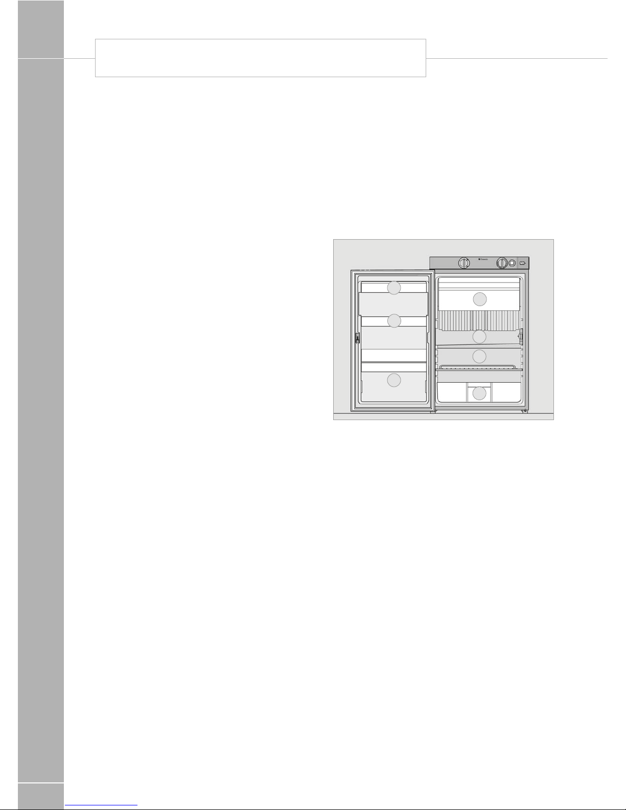
Refrigerator compartments
5
1
6
7
2
3
4
Fig. 37
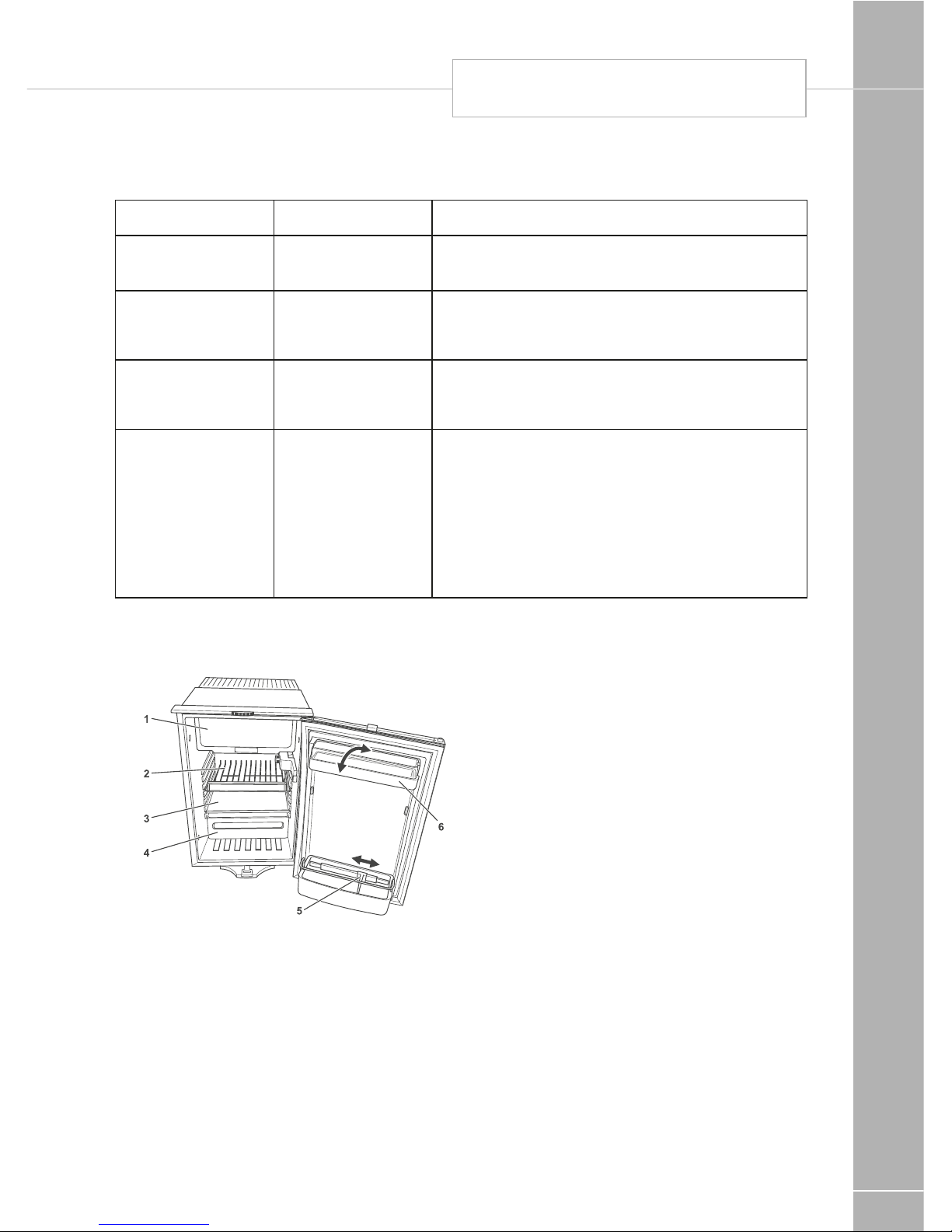
1. Freezer compartment :
already frozen food (deep-frozen food)
2. Middle compartment:
Dairy products, convenience food
3. Bottom compartment:
Meat, fish, food for defrosting
4. Vegetable compartment:
Salads, vegetables, fruit
5. Top door shelf:
Eggs, butter
6. Middle door shelf:
Cans, dressings, ketchup, jam
7. Bottom door shelf (drinks
compartment):
Drinks in bottles or bags
Making ice cubes
Ice cubes are best frozen overnight. At night,
the refrigerator has less work to do and the
unit has more reserves.
DOMETIC ABSORPTION REFRIGERATOR
Page 29
EQUIPMENT DETAILS
107
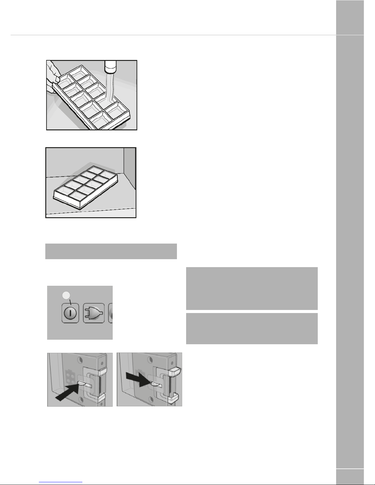
1. Fill the ice cube tray with drinking water.
2. Place the ice cube tray in the freezer
compartment.
! WARNING: Only use drinking water!
Shutting off the refrigerator
Fig. 41
2
Fig. 42
Fig. 43
• Switch off MES and AES models by
pressing button (2). Keep button (2) pressed
for 3 seconds. The display disappears and
the appliance is fully switched off (Fig. 40).
• Release the locking mechanism of the door
lock by pushing it and shift it to the front.
If the door is shut in this position, a small
gap is nevertheless kept open to prevent
formation of mildew.
• If the refrigerator is to be taken out of service
for an extended period of time, close the
onboard shut-off valve and the cylinder valve.
Defrosting
As time goes by, frost builds up on the fins
inside the refrigerator. A layer of frost thicker on
one side may occur and does not represent a
malfunction. When this layer of frost is about
0.118 inches (3 mm) thick, the refrigerator
should be defrosted.
• Switch off the refrigerator, as described in
section 4.17 Shutting of the refrigerator.
• Remove all food and the ice cube tray.
• Leave the refrigerator door open to allow air
to enter and to prevent formation of mildew.
• After defrosting (freezer compartment
and fins free of frost), wipe both cooling
compartments dry with a cloth.
Note: Water thawing in the main
compartment of the refrigerator runs
into an appropriate container at the back
of the refrigerator. From there, the water
evaporates.
! WARNING: The layer of ice must never
be removed forcibly nor may defrosting be
accelerated using a heat source!
Page 30
EQUIPMENT DETAILS
108
Troubleshooting
Failure: The refrigerator does not
cool sufficiently.
Possible cause Action you can take
Inadequate ventilation to the unit Check that the ventilation grilles are not
covered
Thermostat setting is too low Set thermostat to a higher level
The condenser is heavily frosted Check that the refrigerator door closes
properly
Too much warm food has been stores inside
within a short period of time
Allow warm food to cool down before storage
The appliance has been running for only a
short period of time
Check whether the cooling compartment
works after approx 4-5 hours
Ambient temperatures too high Regularly remove ventilation grilles.
Failure: The refrigerator does not cool in
gas operation mode.
Possible cause Action you can take
Gas cylinder empty Change gas cylinder
Is the upstream shut-off device open? Open shut-off device
Air in the gas pipe? Switch off the appliance and start again. Re-
peat this procedure 3-4 times, if necessary.
Failure: The refrigerator does not cool in
12 V operation.
Possible cause Action you can take
On-board fuse defective Fit new fuse
On-board battery displaced Check battery, charge it
Engine not running Start engine
Heating element defective (please refer to
failure indication)
Please inform the Dometic Customer Services.
TROUBLESHOOTING
Page 31
EQUIPMENT DETAILS
109
Failure: The refrigerator does not cool in
230 V operation.
Possible cause Action you can take
On-board fuse defective Fit new fuse
Vehicle not connected to mains supply voltage
Make a connection to a mains power supply
AES: Gas operation despite connection to the
mains supply voltage?
Appliance switches to gas operation due to
insufficient mains supply voltage (automatically
switches back to 230 V operation)
Heating element defective (please refer to
failure indication
Please inform Dometic Customer Services
Information on failure display
and trouble-shooting
• Refrigerators with an electronics system
(MES, AES) indicate the occurence of a
malfunction by the LED or display flashing.
• If a malfunction occurs, the indicator LED
"Failure" (8) flashes simultaneously. In the
case of AES models an acoustic alarm
sounds.
Before notifying the authorised Service Center,
please check whether:
• the instructions in section "Operating the
refrigerator" have been observed.
• the refrigerator stands level.
• it is possible to operate the refrigerator with
any available power source.
Status indicators
MES
Fig. 51
1 2 3 4 6 7 8
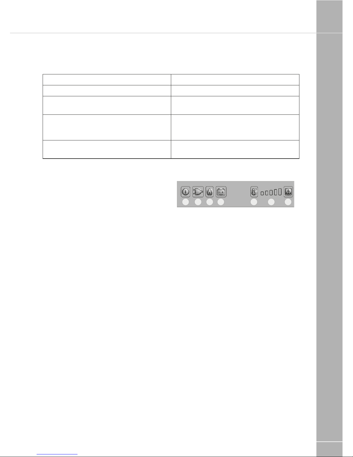
1. Button ON / OFF
2. Energy selector switch 230 V AC
3. Energy selector switch GAS
4. Energy selector switch 12V DC
6. temperature level button
7. temperature level display
8. fault LED / GAS FAULT reset button
Page 32
EQUIPMENT DETAILS
110
Operation with on-board
12 v power supply
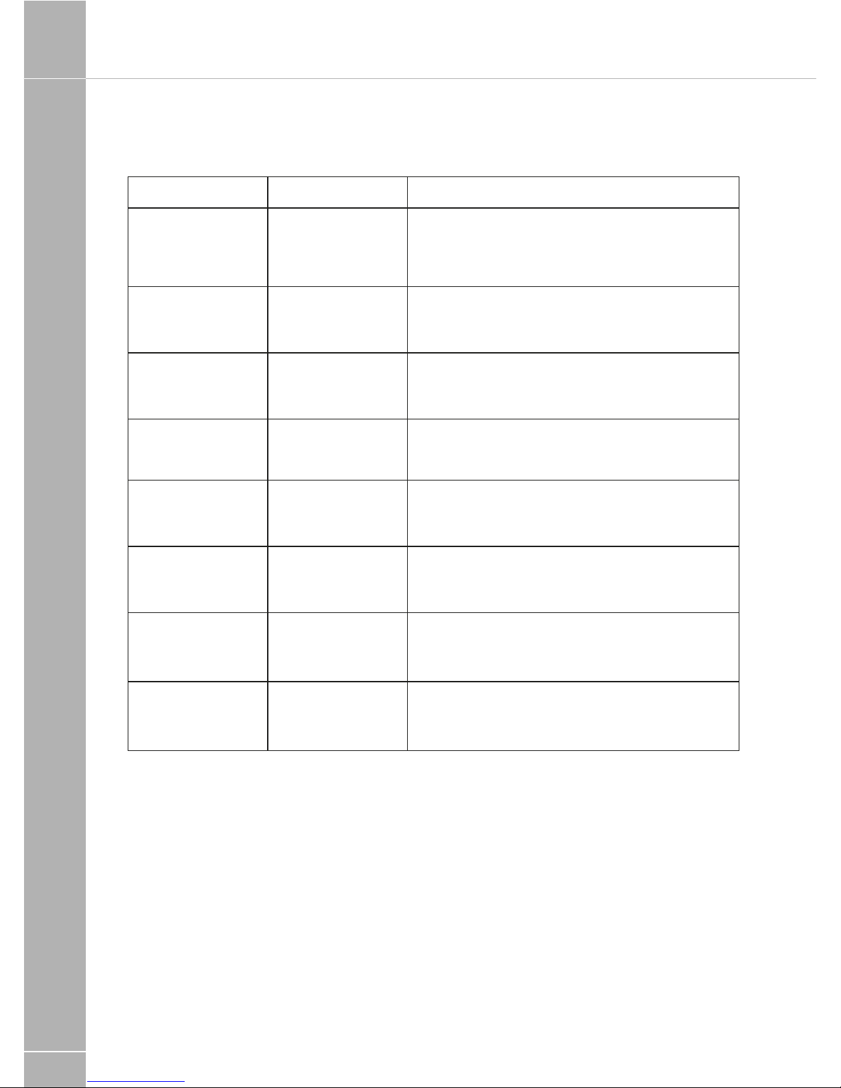
Indicator Fault Remedy
(2) and (8)
flashing and acoustic signal 20s
230 V mode:
"230V" not available or voltage too
low
Check mains power connection, mains voltage,
fuse
(4) and (8)
flashing and acoustic signal 20s
12 V mode:
"12V" not available
or voltage too low
Check 12V connection, on-board battery, fuse
(3) and (8)
flashing and acoustic signal 20s
Gas mode:
Flame not ignited
Check gas supply (gas bottle, gas valve)
Press the (8) button after clearing the fault
Acoustic signal,
15s at two minute
intervals
Interior lighting is
switched on
Close door, check door contact
(2) and (7)
flashing and acoustic signal 20s
230 V mode:
230V heating element defective
Arrange replacement of 230V heating element,
contact Customer Service
(4) and (7)
flashing and acoustic signal 20s
12 V mode:
12V heating element defective
Arrange replacement of 12V heating element,
contact Customer Service
(7)
flashing and acoustic signal 20s
Temperature sensor
without contact or
defective
Contact Customer Service
(3) and (7)
flashing and acoustic signal 20s
Burner defective
or cooling unit
defective
Check burner, burner nozzles, if
necessary contact Customer Service and
arrange replacement
Page 33
EQUIPMENT DETAILS
111
WAECO FRIDGE
Operation with batteries
(internal power supply)
Indicator Fault Remedy
(3) and (8)
flashing brightly
Flame not ignited Check gas supply (gas bottle, gas valve)
Press the (8) button after clearing the fault
(3) and (7)
flashing brightly
Burner defective
or cooling unit
defective
Check burner, burner nozzles, if necessary contact Customer Service and arrange replacement
Acoustic signal at
15 second intervals
Undervoltage
detection (internal
batteries)
Replace batteries
Automatic switching from external
to internal power
supply does not
function (absence
of the onboard 12V
power supply for
the electronics)
Refrigerator does
not function, gas
operation not
possible although
the batteries are
inserted
Switch off the refrigerator and start again
The onboard power supply was interrupted during
the starting of the gas operation
Note: No automatic switching is performed during
the ignition.
Waeco fridge
Before starting your new refrigerator for the first
time, you should clean it inside and outside with
a damp cloth for hygienic reasons (please also
refer to the see ‘Cleaning and care’).
8.1 Energy saving tips
• Allow hot food to cool down first before you
put it in the refrigerator.
• Do not open the refrigerator more often
than necessary.
• Do not leave the door open for longer
than necessary.
• Defrost your refrigerator as soon as a layer of
ice forms.
• Avoid unnecessarily low temperature settings.
• Clean dust and dirt from the condenser at
regular intervals.
8.2 Using the refrigerator
The fridge conserves fresh foodstuffs. The
freezer compartment conserves frozen
foodstuffs and freezes fresh foodstuffs.
Ensure that food or liquids in glass containers
are not excessively cooled. Liquids expand
when they freeze and can thus destroy the
glass containers.Food may only be stored in
its original packaging or in suitable containers.
Page 34
EQUIPMENT DETAILS
112
Ensure that the objects placed in the
refrigerator are suitable for cooling to the
selected temperature.
To switch the refrigerator on:
1. Locate the furniture mounted switch, found
close to the refrigerator, and switch ON.
2. Locate the control dial within the fridge (see
image below) and turn clockwise.
Note: After switching on, the refrigerator
requires approx. 60 s until the compressor
starts up.
Setting the temperature
You can set the temperature to any level using
the control knob. The built-in thermostat
regulates the temperature as follows:
1 least cooling
7 most cooling
The cooling capacity can be influenced by:
• the ambient temperature
• the amount of food to be conserved
• the frequency with which the door is opened.
Conserving foodstuffs
You can conserve foodstuffs in the refrigerator.
The time for which the food can be conserved
in this way is usually stated on the package.
Do not conserve warm food in the refrigerator.
Do not place glass containers containing liquid
in the freezer compartment. Food which can
easily absorb tastes and odours and liquids
and products with a high alcohol content
should be conserved in airtight containers.
The refrigerator is divided in different zones
with different temperatures:
• The colder zones are immediately above the
drawers for fruit and vegetables, near the
back wall.
• Observe the temperature information and
best before date on the food packaging.
Observe the following when using
the refrigerator:
• Never re-freeze products which have started
defrosting or have been defrosted, but
consume them as soon as possible.
• Wrap food in aluminium foil or cling film and
shut in a suitable box with a lid. This ensures
that aromas, the shape and the freshness
will be better conserved.
Defrosting the refrigerator
The appliance has two options to remove the
condensation resulting from operation:
• pass it directly outside: Remove the
drip-tray (1). Connect a hose (2) to the
outlet connections (3).
• collect in the drip-tray: Empty the drip-tray
(1) as required.
Defrosting the freezer
Never use hard or pointed tools to remove ice
or to loosen objects which have frozen
in place.
To defrost the refrigerator, proceed as follows:
• Take the contents out.
• If necessary, place the contents in another
cooling appliance, to keep them cool.
• Set the temperature control knob to ‘0’.
• Leave the door open.
WAECO FRIDGE
Page 35

EQUIPMENT DETAILS
113
Note: The Waeco fridge has an optimum
ambient temperature range of +16Oc to
+32
O
c. Outside this range the efficiency of
the unit may be affected to the point where
the unit may not cool the foodstuffs inside.
Switching off and storing the refrigerator
If you do not intend to use the refrigerator for
a long time, proceed as follows:
• Set the temperature control knob to level ‘0’.
• Disconnect the power cable from the battery
or pull the AC cable plug out of the rectifier.
• Clean the refrigerator.
• Turn the locking wheel (4) anti-clockwise to
the end stop (‘Vent’).
• Close the door until it latches in.
• The door stays open thus preventing smells
from arising.
Replacing the interior light
If the interior light in the refrigerator is faulty,
you can change the bulb (12 V, 3 W).
• Remove the cover.
• Pull the light (5) out of the sheet metal straps.
• Slide in the new lamp between the sheet
metal straps, until it snaps into place.
Change the fuse
(only DC/AC refrigerators).
If the fuse in the rectifier is faulty too, you can
replace this too.
• Lever the fuse compartment (6) open with
a screwdriver.
• Replace the fuse (250 V/3 A).
• Close the fuse compartment again.
Page 36
EQUIPMENT DETAILS
114
9. Cleaning and care
Do not use abrasive cleaning agents or hard
objects during cleaning as these can damage
the refrigerator. Never use hard or pointed
tools to remove ice or to loosen objects which
have frozen in place.
As soon as the refrigerator becomes dirty,
clean it with a damp cloth. Make sure that no
water drips into the seals. This can damage
the electronics. Wipe the refrigerator dry with a
cloth after cleaning.
10. Guarantee
Our general guarantee conditions apply. If the
product is defective, please return it to the
WAECO branch in your country or to your
dealer. For repair and guarantee processing,
please include the following documents when
you send in the appliance:
• A copy of the receipt with purchasing date
• Reason for the claim or a description of
the fault
11. Disposal
Place the packaging material in the appropriate
recycling waste bins wherever possible.
If you wish to scrap the appliance, ask your
local recycling centre or specialist dealer for
details about how to do this in accordance
with the applicable disposal regulations.
12. Troubleshooting
The significance of the red LED (7)
For operational faults it illuminates several
times. The number of pulses depends on the
type of fault.
Each flash lasts for one quarter of a second.
After the series of impulses a pause follows.
The sequence for the fault is repeated every
four seconds.
No. of
flashes
Fault Possible cause
1 Supply
voltage
The supply voltage
is outside of the
set range.
2 Excessive
fan current
The fan loads the
electronics unit
with more than 1 A
3 The motor
doesn’t start
The rotor is
jammed.
The pressure
difference in the
cooling system is
too high
(> 5 bar).
4 Speed too
low
If the cooling
system is
overloaded, the
minimum speed of
the motor of 1850
RPM cannot be
maintained.
5 Overheating
of the
electronics
unit
If the cooling
system is loaded
too heavily or the
temperature is
set too high, the
electronics can
overheat.
WAECO FRIDGE
Page 37

EQUIPMENT DETAILS
115
Interior temperature too low in
control level ‘1’
Fault Possible cause Remedy
Compressor runs constantly Faulty thermostat Change the thermostat
Compressor runs for a
long time
Large quantities have
been frozen in the
freezer compartment
Compressor does not run
(battery connection)
UKL = 0 V There is an interruption in
the connection between the
battery and the – electronics
Main switch faulty (if installed)
Additional supply line fuse
has blown (if installed)
Establish a connection
Replace the main switch
Replace the supply line fuse
UKL ≤ U
EIN
Battery voltage is too low Charge the battery
Start attempt with
U
KL
≤ U
OFF
Loose cables -
Poor contact (corrosion)
Battery capacity too low
Cable cross section too small
Establish a connection
Replace the battery
Replace the cable
Start attempt with
UKL ≤ U
ON
Ambient temperature too high
Insufficient ventilation and/or
air supply
Condenser is dirty
Move the refrigerator to
another location
Clean the condenser
Electric circuit between
the pins in the
compressor interrupted
Defective compressor Replace the compressor
U
KL
Voltage between the positive and negative
terminals of the electronics
U
ON
Cut-in voltage of the electronics
U
OFF
Cut-off voltage of the electronics
Page 38
EQUIPMENT DETAILS
116
Compressor is not running
(connected to AC supply)
Fault Possible cause Remedy
No voltage Interruption in the
supply cable
Main switch faulty
(if installed)
Additional supply line fuse
has blown (if installed)
Establish a connection
Replace the main switch
Replace the supply line fuse
Voltage is present but the
compressor doesn’t run
Ambient temperature too high
Insufficient ventilation and/or
air supply
Condenser is dirty
Move the refrigerator to
another location
Clean the condenser
Electric circuit between
the pins in the compressor
interrupted
Defective compressor Replace the compressor
Poor cooling, interior temperature
increases
Compressor runs for a long
time/continuously
Ambient temperature too high
Insufficient ventilation and/or
air supply
Condenser is dirty
Faulty fan
Move the refrigerator to
another location
Clean the condenser
Replace the fan
Compressor runs
intermittently
Battery capacity exhausted Charge the battery
Unusual noises
Loud humming A component of the refrigerant
circuit cannot move freely
(touching the wall)
Foreign body jammed
between the cooling unit and
the wall
Fan noise
Bend the component carefully
away from the obstruction
Remove the foreign body
TROUBLESHOOTING
Page 39

EQUIPMENT DETAILS
117
Spinflo oven
! WARNING: Before using the appliances
for the first time, remove all accessories and
packing in the grill and oven, including any
surface protection film, i.e. plastic coating.
Clean all interior surfaces with hot soapy
water to remove any residual protective
covering of oil and rinse carefully.
! WARNING: Accessible parts may be hot
when the grill is used, young children should
be kept away. When cooking always ensure
young children are kept away.
Ensure the gas cylinder is turned on. In the
event of a gas smell, turn off at the cylinder and
contact supplier. The burners on this appliance
have fixed aeration and no adjustment is
required. Depending on the gas being used, the
burners should flame as follows:
Propane: The flames should burn quietly with
a blue/green colour with no sign of yellow tips.
Butane: Normally on initial lighting, as small
amount of yellow tipping will occur and then
slightly increases as the burner heats up.
! WARNING: The control tap on this
appliance operates both the grill and oven
burners. To ensure safe operation it is not
possible to operate both burners at the
same time.
Using the hob burners
1. Ensure gas cylinder/supply is connected
and turned on. In the event of a gas
smell turn off at gas cylinder/mains and
contact supplier
2. Flame supervision: Each burner is
controlled individually and is monitored
by a thermocouple probe. In the event
of the burner flames being accidentally
extinguished, turn off the burner control and
do not attempt to re-ignite the burner for at
least one minute.
3. To light: Push in the control knob and turn to
full rate - see Fig.2. Hold a lighted match or
taper to the burner and push the control knob
in and hold. It is necessary to hold the knob
depressed after the burner has ignited or
approximately 10-15 seconds, to allow the
thermocouple probe to reach temperature,
before releasing the knob. Should the flame
go out when the knob is released, the
procedure should be repeated holding the
knob depressed for slightly longer.
4. For models fitted with spark ignition the
procedure is similar except that the burner
can be ignited by depressing the ignition
button, which is located on the fascia. If
the burner has not lit within 15 seconds
the control knob should be released and
the burner left for at least 1 minute before a
further attempt to ignite the burner.
5. For simmering, turn the knob further
anti-clockwise to the low rate position.
6. To turn off: Turn the control know until the
line on the control knob is aligned with the
dot on the control panel. Always make
sure the control knob is in the off position
when you have finished using the hotplate
burners.
! WARNING: The two in line hob burners
on this appliance will support pans from
10cm to 20cm. The single hob burner will
support pans from 10cm to 22cm.
! WARNING: Glass lids may shatter when
heated. Turn off the hotplate and allow it to
cool before closing the glass lid. Remove
all spillage from the surface of the glass lid
before opening.
! WARNING: The use of the electric
hotplate and gas hobs will generate heat.
We recommend, to avoid excess build-up
of heat around the cooker area, the window
is left opened when cooking to allow for
additional ventilation.
SPINFLO OVEN
Page 40

EQUIPMENT DETAILS
118
Using the hotplate
Ensure the electricity is switched on.
The hotplate control is numbered from 1 to 6.
To turn it on, rotate the knob either clockwise
or anti-clockwise to the required position.
Position 1 is the coolest setting. To turn the
hotplate off, rotate the knob until the line or
pointer on the knob lines up with the zero on
the control panel.
The hotplate is a sealed construction and
transfers heat through conduction. For
maximum efficiency a correctly sized pan with
a flat heavy gauge base should be used. Pan
size should be the same or slightly larger (up to
1”/2.5cm oversize).
Before using your hotplate for the first time, we
recommend that you prime and then season it.
To prime the Hotplate
Switch on the hotplate for a short period,
without a pan, to harden and burn off the
coating. Use a medium to high setting for 3 - 5
minutes. A non toxic smoke may occur during
this process. Allow it to cool, then season.
To season the Hotplate
First heat the hotplate for 30 seconds on
a medium setting, then switch off. Pour a
minimal amount of unsalted vegetable oil onto
a clean dry cloth or paper towel, and apply a
thin coat of oil to the hotplate surface. Wipe
off any excess oil, then heat the hotplate on
a medium setting for 1 minute. Occasional
seasoning will help to maintain the Hotplate’s
appearance.
Using the grill
! WARNING: The grill must only be used
with the door open. The heat deflector
below the fascia should be pulled out
prior to lighting the grill. Never adjust the
heat deflector position without using hand
protection i.e. oven gloves.
1. Ensure gas cylinder/supply is connected
and turned on. In the event of a gas smell
turn off at gas cylinder/mains and contact
supplier.
2. To light: Open door, push in the control
knob and turn to full rate - see Fig 2.
Hold alighted match or taper to the burner
and push the control knob in and hold.
The burner should ignite and the control
knob should be held in for 10-15 seconds
before release. If the burner goes out, repeat
procedure holding control knob for slightly
longer.
3. For models fitted with spark ignition the
procedure is similar except that the burner
can be ignited by depressing the ignition
button, which is located on the fascia.
Ignition must be carried out with the door
open, and if the burner has not lit within
15 seconds the control knob should be
released and the grill left for at least 1
minute before a further attempt to ignite the
burner.
4. On first use of the grill, it should be heated
for about 20 minutes to eliminate any
residual factory lubricants that might impart
unpleasant smells to the food being cooked.
An non-toxic smoke may occur when using
for the first time so open any windows
and turn on mechanical ventilators to help
remove the smoke.
5. Although the grill does heat up quickly, it is
recommended that a few minutes pre-heat
be allowed.
6. Flame Failure Device (FFD): The grill burner
is fitted with a flame sensing probe, which
will automatically cut off the gas supply
in the event of the flame going out. In the
event of the burner flames accidentally
being extinguished, turn off the burner
control and do not attempt to re-ignite the
burner for at least one minute.
7. It is normal for the flames on this burner
to develop yellow tips as it heats up,
particularly on Butane.
8. A reversible grill pan trivet enables the
correct grilling height to be achieved.
SPINFLO OVEN
Page 41

EQUIPMENT DETAILS
119
Fast toasting - trivet in high position
Grilling sausages - trivet in high position
Grilling steak/bacon - trivet in high position
Grilling chops, etc. - trivet in low position
Slow grilling - trivet removed
9. To turn off: Turn the control knob until the
line on the control knob is aligned with the
dot on the control panel. Always make sure
the control knob is in the off position when
you have finished grilling.
! WARNING: The pan supplied with the
appliance is multi functional, for use either
whilst grilling or when using the oven. The
handle design allows removal or insertion
whilst the pan is in use.vv
Using the oven
1. Ensure gas cylinder/supply is connected
and turned on. In the event of a gas
smell turn off at gas cylinder/mains and
contact supplier.
2. To light: Open door, push in the control
knob and turn to gas mark 9. Hold a lighted
match or taper to the burner and push the
control knob in and hold. The burner should
ignite and the control knob should be held
in for 10-15 seconds before release. If the
burner goes out, repeat the process holding
control knob for slightly longer.
3. For models fitted with spark ignition the
procedure is similar except that the burner
can be ignited by depressing the ignition
button, which is located on the fascia.
Ignition must be carried out with the door
open, and if the burner has not lit within
15 seconds the control knob should be
released and the oven left for at least one
minute before a further attempt to ignite
the burner.
4. Place the oven shelf in the required position
and close the door. Set control knob to
approximately gas mark 5 and heat the
oven for about 30 minutes to eliminate
any residual factory lubricants that might
impart unpleasant smells to the meals being
cooked. A non-toxic smoke may occur
when using for the first time so open any
windows and turn on mechanical ventilators
to help remove the smoke.
5. Although the oven does heat up quickly, it
is recommended that a 10 minute pre-heat
should be allowed. The oven should be up
to full temperature in about 15-20 minutes.
6. To turn off: Turn the control knob until the
line on the control knob is aligned with the
dot on the control panel.
7. Shelf: The shelf has been designed to allow
good circulation at the rear of the oven and
are also fitted with a raised bar to prevent
trays or dishes making contact with the
back of the oven. To remove a shelf, pull
forward until it stops, raise at front and
remove.
Oven temperature control
The temperature in the oven is controlled by
a thermostatic gas tap and is variable over
the range 130ºC to 240ºC. Approximate
temperatures for the settings on the control
knob are shown in the table below. The
temperatures indicated refer to the centre of
the oven and at any particular setting the oven
will be hotter at the top and cooler towards
the base.
The variation between top and centre, and
centre to bottom is approximately equivalent
to one gas mark. Good use can be made
of the temperature variation in several
dishes requiring different temperatures may
be cooked at the same time. In this way
maximum benefit can be obtained from the
gas used to heat the oven. Care should be
taken not to overload the oven, adequate
spacing being used to allow free circulation
for heat.
Page 42
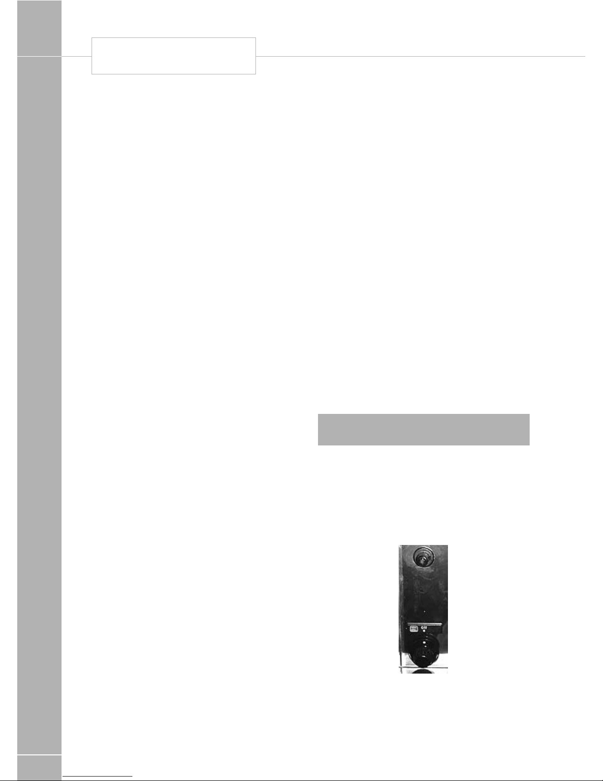
EQUIPMENT DETAILS
120
Cooking guidelines
See user instructions.
Do’s and Don’ts
Do read the user instructions carefully before
using the appliance for the first time.
Do allow the oven to heat before using for the
first time, in order to expel any smells before
the introduction of food.
Do clean the appliance regularly.
Do remove spills as soon as they occur.
Do always use oven gloves when removing
food shelves and trays from the oven.
Do check that controls are in the off position.
Don't allow children near the cooker when in
use. Turn pan handles away from the front so
that they cannot be caught accidentally.
Don't allow fats or oils to build up in the oven
tray or base.
Don't use abrasive cleaners or powders that
will scratch the surfaces of the appliance.
Don't under any circumstances use the oven
as a space heater.
Don't put heavy objects onto open grill and
oven doors.
Leaks
If a smell of gas becomes apparent, the
supply should be turned off at the cylinder
IMMEDIATELY. Extinguish naked lights
including cigarettes and pipes. Do not operate
electrical switches. Open all doors and
windows to disperse any gas escape. Butane/
Propane gas is heavier than air; any escaping
gas will therefore collect at low level. The
strong unpleasant smell of gas will enable the
general area of the leak to be detected. Check
that the gas is not escaping from an unlighted
appliance. Never check for leaks with a naked
flame, leak investigation should be carried out
using a leak detector spray.
Smev mini grill
Use the appliance only in a well
ventilated space.
The ventilation openings must remain open
when the appliances are operating.
Ignition of the appliance
1. Manual ignition: oven - grill
a. Push in control knob, slightly turn to ignition
position (fig l) light burner with match or
lighter keeping knob pushed in the knob for
5 - 10 sec.
b. Release knob and turn it lo required
position.
2. Automatic ignition: oven - grill
a. For igniting oven or grill, open oven door
completely
b. Push In control knob, slightly turn to ignition
position keeping it pushed in for 5 - 10sec.
c. Release knob and turn it to designed
position.
Note: Oven and grill burners will not light, if
door is not completely open.
3. Ignition of appliances with thermostat
Proceed according to paragraphs 1 and 2,
with or without electronic ignition. The ignition
position is obtained by turning control knob on
a position between 1and 6 for the oven and
grill position (see symbol tttt)
For ovens with thermostat the different
positions of the knob correspond to the
following temperatures in °C of the oven
SMEV MINI GRILL
Page 43
EQUIPMENT DETAILS
121
! WARNING: If ignition is unsuccessful,
repeat operation from beginning; if
necessary. have the appliance checked if a
gas and/or electricity failure in the appliance.
If appliance absolutely does not work, close
gas inlet tap and contact retailer. Before
using oven for the first lime, let it run at
maximum temperature for the duration of 20
mins without foodstuffs inside:
! WARNING: Use gloves when handling
hot elements!
In the event of the burner flames being
accidentally extinguished, turn off the burner
control and do not attempt re-ignite the burner
for at least 1 min.
Operation of the grill
a. Pull out heat protection plate
b. Light grill burner.
c. Keep oven door half-open
d. Do not use for more then 20 minutes.
POS
1 2 3 4 5 6
TEMP
130 160 180 200 220 240
Use of the rotisserie
Insert dripping-pan with the rotisserie installed
as indicated in (fig 5a). Push in the appropriate
button (fig 4a) in order to set going the
rotisserie motor.
Use of the Grill
a. Slide out heat protection plate “P” (fig.’ 5)
b. Light grill burner
c. Keep oven door in half-open position (fig. 5)
Use with Oven:
a. Light oven burner
b. Position control knob on desired
temperature
c. Close oven door.
Smev hotplates
Use the appliance only in a well
ventilated space.
To use
1. Ensure gas cyclinder is connected and
turned on and the shut off valve at the
manifold is open. In the event of a gas smell
turn off at gas cylinder and contact supplier.
2. Flame supervision: Each burner is
controlled individually and is monitored by
a thermocouple probe. In the event of the
burner flames being accidently extinguished,
turn off the burner control and do not
attempt to re-ignite the burner for at least
one minute.
The ventilation openings must remain open
when the appliances are operating.
SMEV HOTPLATES
Page 44
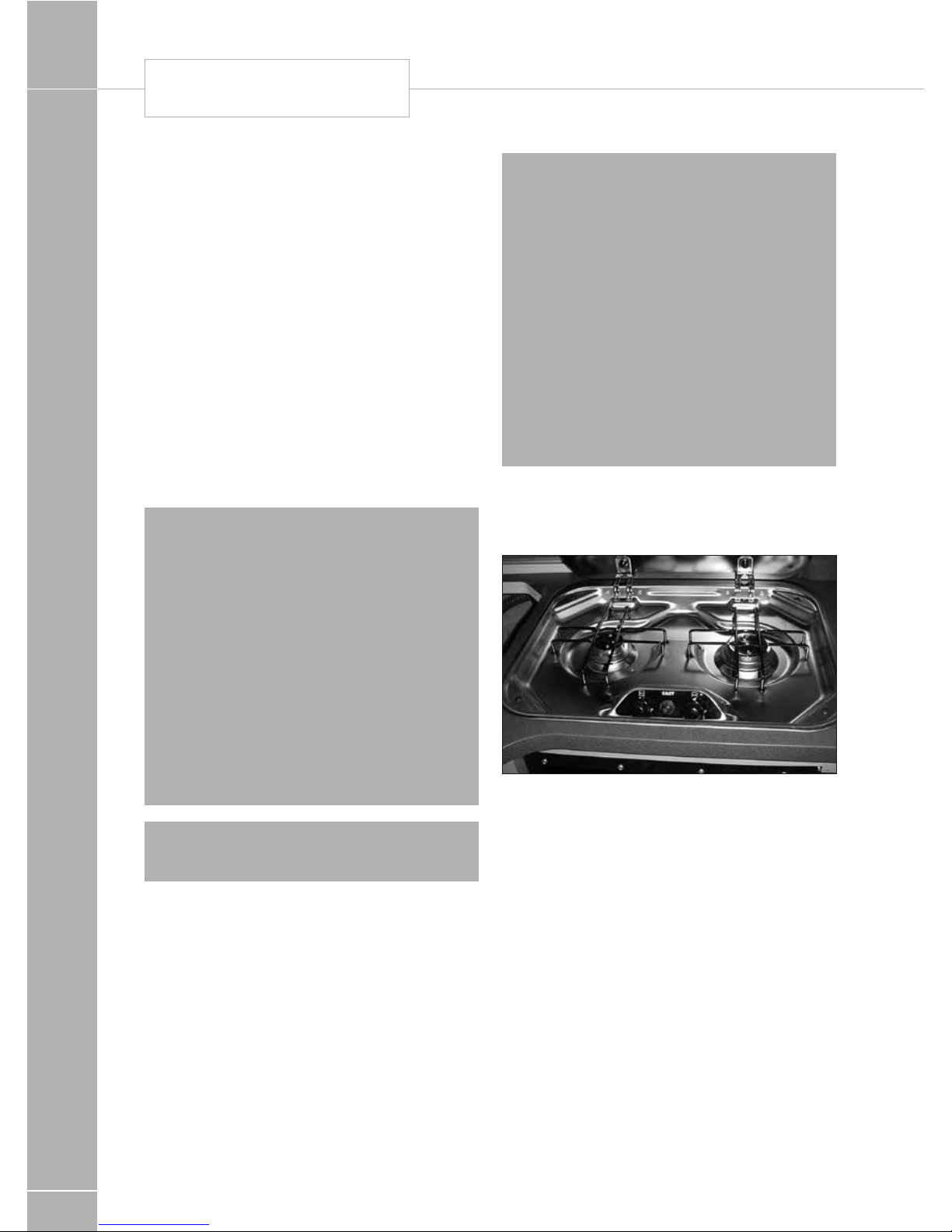
EQUIPMENT DETAILS
122
Ignition of the appliance
1. Manual ignltion hotplate
a. Push in control knob, slightly turn to ignition
position (big flame).
Light burner with match or lighter keeping
knob pushed In for 5 – 10 sec.
b. Release knob and turn it to the required
position (big or small flame).
2. Automatic ignltion: hotplate
a. Push in control knob, slightly turn to ignition
position (big flame). Light the burner by
pressing the ignition key and holding down
the knob for 5- l0 seconds.
b. Release knob and turn it to required
position.
! WARNING: If ignition is unsuccessful,
repeat operation from beginning; if
necessary have the appliance checked if
a gas and/or electricity failure in the
appliance. If appliance absolutely does not
work, close gas inlet tap and contact retailer.
Pans of a diameter ranging from l0 to 22 cm
may be used.
During grill operation, do not obstruct the
hole in the centre of the burners where heat
and smoke can come out. The heat coming
out of this hole may be used to heat up or
cook food by placing a saucepan or frying
pan over it.
! WARNING: Use gloves when handling
hot elements.
Never lay Pyrex lids or other items on the
burners. Cooking facilities must not be used to
heat the environment.
The slots indicated in fig. 5 must be kept open.
Visual flame control
a. The flame is right, when its internal tongue is
blue and its outline well defined.
b. If the flames have yellow tips and little
pressure , consult your dealer.
LEAKS
If a smell of gas becomes apparent, the
supply should be turned off at the cylinder
IMMEDIATELY. Extinguish naked lights
including cigarettes and pipes. Do not
operate electrical switches. Open all doors
and windows to disperse any gas escape.
LPG gas is heavier than air; any escaping
gas will therefore collect at a low level. The
strong unpleasant smell of gas will enable
the general of the leak to be detected.
Check that the gas is not escaping from an
unlighted appliance. Never check for leaks
with a naked flame, leak investigation should
be carried out using a leak detector spray.
Cleaning instructions
Do not use chemical or abrasive detergents.
SMEV HOTPLATES
Page 45
EQUIPMENT DETAILS
123
Microwave oven general
user instructions
Always refer to the microwave operating
instructions supplied with the vehicle
Precautions to avoid possible exposure to
excessive microwave energy
a. Do not attempt to operate this oven with
the door open since open door operation
can result in harmful exposure to microwave
energy. It is important not to defeat or
tamper with the safety interlocks.
b. Do not place any objects between the oven
front face of the door or allow soil or cleaner
residue to accumulate on sealing surfaces.
! WARNING:
c. if the door or door seals are damaged,
the oven must not be operated until it has
been repaired by a competent person
(1) door broken (2) hinges and latches
(broken or loosened), (3) door seals and
sealing surfaces.
! WARNING:
d. it is hazardous for anyone other than a
competent person to carry out a service
or repair operation.
! WARNING:
e. liquids or other foods must not be heated
in sealed containers since they are liable
to explode.
! WARNING:
f. only allow children to use the oven without
supervision when adequate instruction has
been given so that the child is able to use
the oven in a safe
way and understands the hazards of
improper use.
! WARNING:
g. when the appliance is operated in the
combination mode, children should only
use the oven under adult supervision due
to the temperature generated. (if provided)
Important safety guidance
! WARNING: To prevent fire, burns,
electric shock and other warnings. Listed
below are, as with all appliances, certain
rules to follow and safeguards to assure high
performance from this oven:
Important instructions
1. Do not use the oven for any reason other
than food preparation, such as for drying
clothes, paper, or any other non food items
or for sterilizing purposes.
2. Do not use the oven when empty, this could
damage the oven.
3. Do not use the oven cavity for any type
of storage, such as papers, cookbook,
cookware etc.
4 Do not operate the oven without the glass
tray in place. Be sure it is sitting properly on
the rotating base.
5. Make sure you remove caps or lids prior
to cooking when you cook food sealed in
bottles.
6. Do not put foreign material between the
oven surface and door. It could result in
excessive leakage of microwave energy.
7. Do not use recycled paper products for
cooking. They may contain impurities which
could cause sparks and/or fires when used
during cooking.
8. Do not pop popcorn unless popped in a
microwave approved popcorn popper or
unless it’s commercially packaged and
recommended especially for microwave
ovens. Microwave popped corn produces
a lower yield than conventional popping;
there will be a number of unpopped kernels.
Do not use oil unless specified by the
manufacturer.
9. Do not cook any food surrounded by a
membrane, such as egg yolks, potatoes,
chicken livers, etc., without first piercing
them several times with a fork.
MICROWAVE
Page 46

EQUIPMENT DETAILS
124
10. Do not pop popcorn longer than the
manufacturer’s directions. (Popping time
is generally below 3minutes). Longer
cooking does not yield more popped
corn it can cause scorching and fire. Also,
the cooking tray can become too hot to
handle or may break.
11. If smoke is observed, switch off or unplug
the appliance and keep the door closed in
order to stifle any flames.
12. When heating food in plastic or paper
containers, keep an eye on the oven due
to the possibility of ignition.
13. The contents of feeding bottles and baby
food jars shall be stirred or shaken and the
temperature checked before consumption,
in order to avoid burns.
14. Always test the temperature of food
or drink which has been heated in a
microwave oven before you give it to
somebody, especially to children or elderly
people. This is important because things
which have been heated in a microwave
oven carry on getting hotter even though
the microwave oven cooking has stopped.
15. Eggs in their shell and whole hard-boiled
eggs should not be heated in microwave
ovens since they may explode, even after
microwave heating has ended.
16. Keep the waveguide cover clean at all
times. Wipe the oven interior with a soft
damp cloth after each use. If you leave
grease or fat anywhere in the cavity it may
overheat, smoke or even catch fire when
next using the oven.
17. Never heat oil or fat for deep frying as you
cannot control the temperature and doing
so may lead to overheating and fire.
18. Liquids, such as water, coffee, or tea are
able to be overheated beyond the boiling
point without appearing lo be boiling due
to surface tension of the Iiquid. Visible
bubbling or boiling when the container is
removed from the microwave oven is not
always present. This could result in very
hot liquid suddenly boiling over when
a spoon or other utensil is inserted
into the liquid.
To reduce the risk of injury to persons:
a. Do not overheat the liquid.
b. Stir the Iiquid both before and halfway
through heating it.
c. Do not use straight-sided containers with
narrow necks.
d. After heating, allow the container to stand in
the microwave oven for a short time before
removing the container
e. Use extreme care when inserting a spoon or
other utensil into the container.
Care of the microwave
1. Turn the oven off before cleaning
2. Keep the inside of the oven clean. When
food spatters or spilled liquids adhere to
oven walls, wipe with a damp cloth. Mild
detergent may be used if the oven gets
very dirty. The use of harsh detergent or
abrasives is not recommended.
3. The outside oven surface should be cleaned
with soap and water, rinsed and dried
with a soft cloth. To prevent damage to
the operating parts inside the oven, water
should not be allowed to seep into the
ventilation openings.
4. If the central panel becomes wet, clean
with a soft dry cloth. Do not use harsh
detergents or abrasives on Control Panel.
5. If steam accumulates inside or around
the outside of the oven door, wipe with
a soft cloth. This may occur when the
microwave oven is operated under high
humidity conditions and in no way indicates
malfunction of the unit.
6. It is occasionally necessary to remove the
glass tray for cleaning. Wash the tray in
warm sudsy water or in a dishwasher.
7. The roller guide and oven cavity floor should
be cleaned regular/y to avoid excessive
noise. Simply wipe the bottom surface
of the oven with mild detergent water or
window cleaner and dry. The roller guide
may be washed in mild sudsy water.
MICROWAVE
Page 47
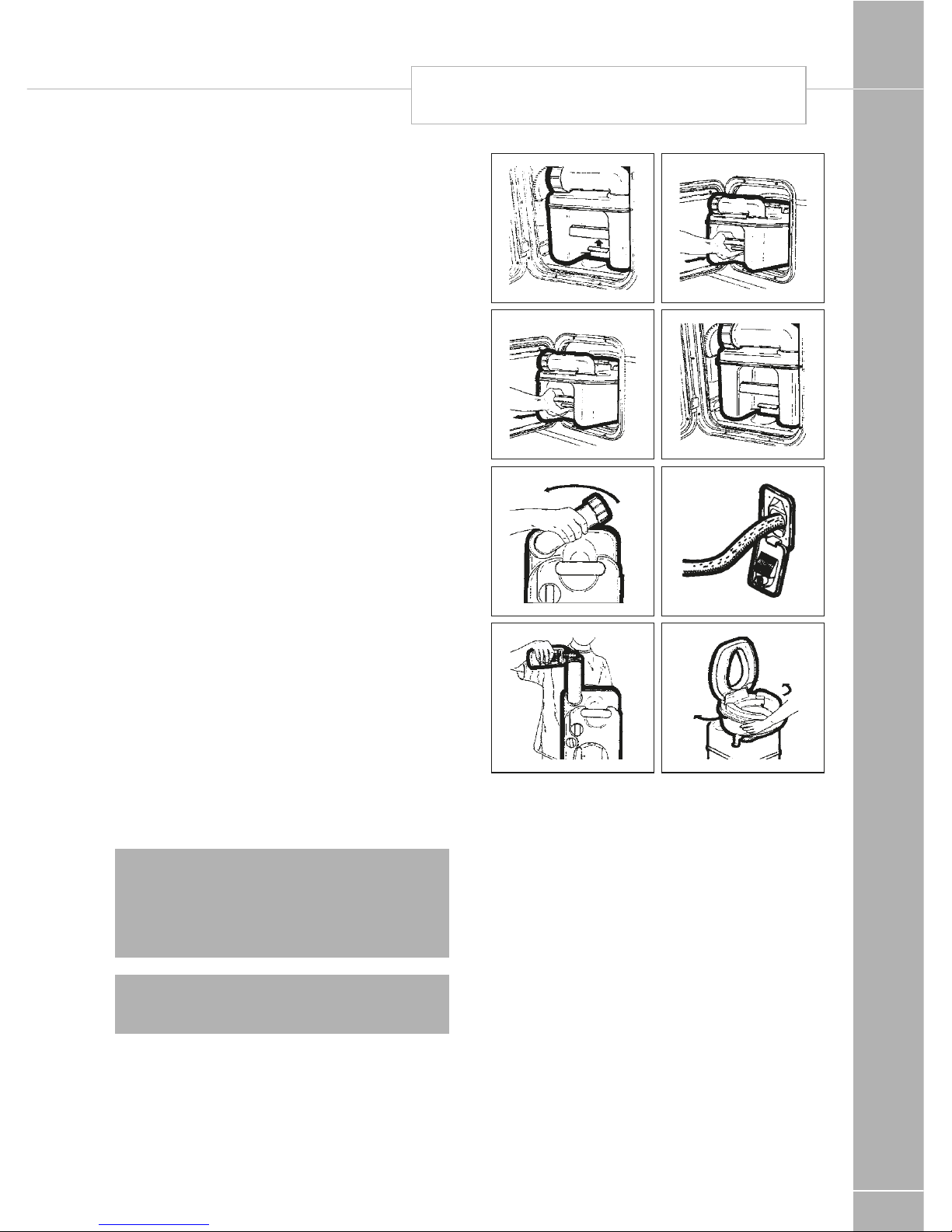
EQUIPMENT DETAILS
125
8. The oven should be cleaned regularly and
any food deposits removed;
9. Failure to maintain the oven in a clean
condition could lead to deterioration of the
surface that could adversely affect the life
of the appliance and possibly result in a
hazardous situation.
Thetford cassette toilet
Cassette C-200CS and C200S
The toilet section of the C-200 includes a
rotatable bowl, removable seat and cover,
a console with a flush handle/flush buttons,
a built in flush-watertank and a waste level
warning indicator. The valve blade handle is
located underneath the bowl.
Preparing for Use
1. Open access door pull retaining clip
upwards (fig. 1).
2. Remove holding tank by pulling straight out.
When holding tank hits the stop, tilt front
end downwards slightly and remove (fig. 2).
3. Position tank vertically and swivel pour out
spout upwards (fig. 3).
4. Remove the cap of the pour out spout. Add
required quantity of toilet fluid through pourout spout then add approx. 2 litres of water
through the spout to cover holding tank
bottom. Replace cap and return pour out
spout to its original stored position (fig. 4).
Note: Warmer weather or longer intervals
between emptying the waste tank may
require additional toilet fluid. Use only
Thetford toilet fluid to achieve the best
results.
! WARNING: Never add toilet fluid directly
into toilet bowl.
1
2
3
4
5
6
7
8
5. Slide the holding tank into position through
access door (fig. 5).
6. Make sure the holding tank is secured by
the retaining clip. (fig. 6).
7. Open the waterfill door and add 50 ml of
Aqua Rinse. Aqua Rinse results in a better
flush and improves the hygiene of the toilet.
Then fill the watertank with fresh water
using a jerrycan or a hose. Tank capacity is
7 litres (fig. 7).
THETFORD CASSETTE TOILET
Page 48
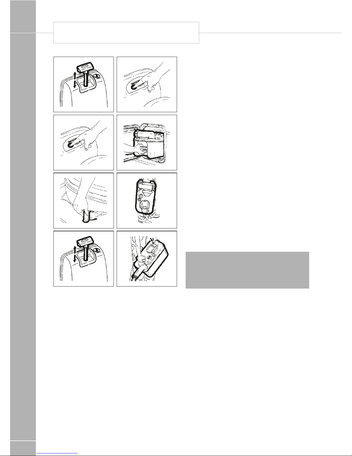
EQUIPMENT DETAILS
126
10
11
9
9a
13
14
11a
12
Operation
8. Turn the bowl in the most comfortable
position (fig. 8).
9. C-200 CW only: Before using the toilet it is
recommended to flush some water into the
bowl by lifting and pressing down the flush
handle (fig. 9).
9a. C-200 CWE & CS only: Before using the
toilet it is recommended to flush some
water into the bowl by pressing and
releasing the flush button (fig. 9a).
10. The toilet may be used with the blade
open or closed. Pull valve handle towards
you to open (fig. 10).
11. C-200 CW only: After use, open valve
blade (if still closed) and flush, lift the flush
handle and press it down (fig. 11). After
flushing, close the blade by turning the
blade handle.
11a. C-200 CWE & CS only: After use, open
valve blade (if still closed) and flush, press
the flush button (fig. 11a).
After flushing, close the blade by turning the
blade handle.
The waste holding tank is located underneath
the toilet and is removed for emptying from
the outside of the vehicle through an access
door. A rotating pour out spout, automatic
holding tank vent, air release valve, valve
blade, carrying handles and hand grip are
incorporated in the waste holding tank. A
sliding cover guarantees optimal hygiene.
Emptying the Holding Tank
The holding tank capacity is approx. 17 litres
and the tank should be emptied when the
waste-level indicator lights up. The wastelevel indicator lights up when the holding tank
contains more than 15 litres of waste.
! WARNING: Do not allow the holding
tank to become overfilled. See trouble
shooting section for emergency emptying
procedure.
12. Open access door and remove the
holding tank. The holding tank can only be
removed when the valve blade is closed
(fig. 12).
13. Carry the holding tank to a normal
household type toilet or other authorised
disposal point. Place the holding tank in
vertical position and rotate pour out spout
upwards (fig. 13).
14. Remove the spout cap. Grasp unit by
upper carrying handle nearest to pour
out spout. Place other hand on upper
rear hand grip so that vent button can be
depressed with the thumb while emptying.
This ensures a smooth outflow of the tank
contents. (fig. 14).
THETFORD CASSETTE TOILET
Page 49

EQUIPMENT DETAILS
127
Note: Only depress the vent button when
pour out spout is pointed downwards.
Rinse the holding tank with clean water. For
preparing for use again, see steps 1 to 7.
Cleaning and maintenance
The lipseal and the seal of the automatic vent
are made of rubber and therefore these parts
need regular maintenance (depending on
frequency of use, once or twice a month).
Lipseal: Remove the sliding cover. Open the
valve-blade by turning the blade-opener knob
anticlockwise. Clean the seal with water. Dry
the seal and grease with silicone spray/oil or
vegetable oil.
Seal of automatic vent: Turn the automatic
vent 60° anticlockwise and remove gently.
Clean the seal with water. Dry the seal and
grease with silicone spray/oil or vegetable oil.
To clean the holding tank, empty the tank,
and rinse with clean water. Use a mild soap
to clean toilet bowl, seat and cover, as well as
exterior of toilet unit and holding tank.
Note: Do not use strong household
detergents or cleaners that contain chlorine,
solvents or acid contents.
Wintering/storage
The Thetford Cassette C-200 CW/CWE/CS is
easily winterised for storage.
Empty remaining fresh water into the bowl
by activating the flush handle up and down
(C-200 CW) or by pressing the flush button
(C-200 CWE & CS).
Once pump has been cleared and water flow
has stopped completely, release into waste
tank. Remove waste tank and empty contents
in normal way.
To evacuate any remaining water from the
fresh water tank. place a container underneath
the drainplug and remove drainplug.
When procedure has been completed replace
drainplug and waste holding tank (fig. 15).
Clean the seals and grease them after drying
(see cleaning and maintenance).
Leave the blade of the holding tank open.
Do not replace cap on the pour out spout, to
ventilate the holding tank. (Also grease the seal
of the pour out spout cap.)
Cold weather use
The toilet can be used in cold weather
conditions provided that the toilet is in heated
surroundings. If this is not the case, you can
use a nontoxic antifreeze (propylene glycol)
or an antifreeze such as those used in car
radiators. Add the antifreeze to the water in
the tank. Add the quantity specified in the
instructions, paying due regard to the safety
instructions.
High altitude and warm weather use
Pressure may build up in the holding tank if
the tank is not inserted while driving at high
altitudes or in warm weather conditions. The
automatic holding tank vent will vent the tank
when there is over- or under-pressure. High
temperatures may require additional Thetford
toilet fluid.
Thetford warranty
1. The Thetford Cassette is warranted for one
year from the date of purchase, please fill in
and return the warranty card.
2. The warranty covers replacement of
defective or flawed parts and the inadequate
performance of the toilet.
3. In case of a defect apply to an original
dealer or Thetford Service Centre with proof
of purchase.
4. Defects, which in our judgement occurred
from misuse, negligence or accident, are
not covered by the warranty. In addition,
the warranty does not apply if the product
is installed or handled improperly or if other
than the prescribed toilet fluids have been
used or if the product has been altered in
any way or has been repaired by unqualified
persons, or if the serial number and/or date
has been altered or removed.
5. Should the original buyer wish to return to
us parts believed to be defective, the parts
should be sent prepaid. If we find the parts
defective and covered by warranty, they will
be repaired and returned. If warranty does
Page 50
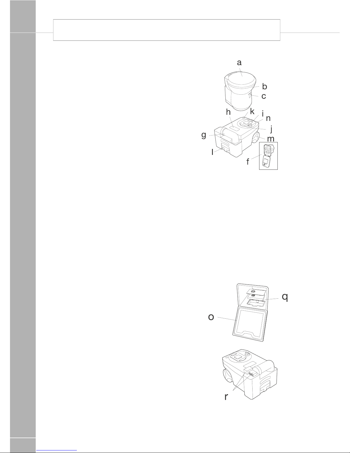
EQUIPMENT DETAILS
128
not apply or has expired, a nominal charge
will be made. Any transport costs are for the
account of the owner.
6. Before returning product or parts they
should be properly cleaned, in order to carry
out inspection and repair.
7. No other warranty is given and no
personal representative is authorised
to make any warranty other than that is
contained herein.
Thetford C260 and
C260S cassette toilet
The Thetford Cassette Toilet is a high quality
product. The toilet forms an integral part of
your caravan or motorhome bathroom, thanks
to its functional design which combines modern styling and ease of use. The C-250 Cassette Toilet is manufactured from high quality
synthetic materials which makes it a durable,
user and maintenance friendly toilet.
The toilet is made up of two parts: a
permanently fixed part and a Waste Holding
Tank that is accessible from the outside. The
removable Waste Holding Tank is located
under the toilet bowl and can be removed
via a door on the outside of the caravan or
motorhome. The Thetford Cassette Toilet is
the solution to the sanitary problem in your
caravan or motorhome!
These instructions cover the C-250CWE this
has its own flush-water tank.
Parts
a. Removable Seat and Lid
b. Swivelling Toilet Bowl
c. Blade Handle
d. Flush Button
e. Waste Holding Tank Level Indicator
f. Water Filling Door (only if toilet has own
flush-water tank)
g. Rotating Emptying Spout
h. Automatic Pressure Release Vent
i. Sliding Cover
j. Removable Mechanism
k. Vent Plunger
l. Pull-Out Handle
m. Wheels
n. Blade Opener
o. Access Door to Waste Holding Tank
THETFORD C260 AND C260S CASSETTE TOILET
Page 51
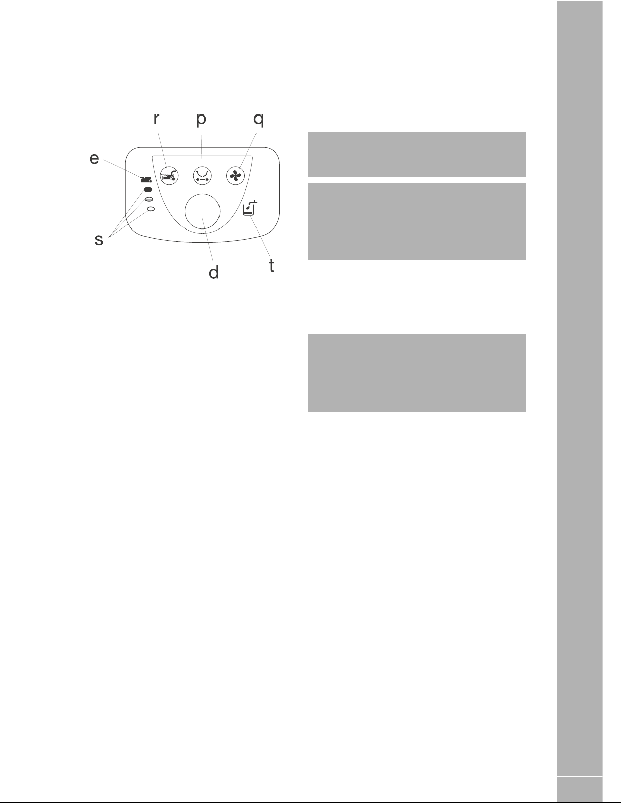
EQUIPMENT DETAILS
129
Optional Features
p. Electric Blade
q. Automatic Ventilator
r. Waste Pump-Out System
s. Waste Holding Tank Multi-Level Indicator
t. Flush-Water Tank Level Indicator (only if toilet
has its own flush-water tank)
Control panel
Preparing for use (standard)
1. Open the access door on the outside of
your caravan or motorhome
2. Remove the Waste Holding Tank by pulling
the safety catch (which holds the tank in
place) upwards.
3. Pull the Waste Holding Tank outward to the
stop. Tip it slightly and take the tank fully out.
4. Place the tank upright and turn the rotating
emptying spout upwards. The emptying
spout ensures that the tank can be easily
and hygienically emptied.
5. Remove the cap, with the measuring cup
inside, from the emptying spout and pour
the correct dosage of Thetford toilet fluid
(see product label) into the holding tank.
This avoids unpleasant smells and keeps
the inside of the tank clean. Next add
approximately 2 litres of water - enough to
ensure that the bottom of the Waste Holding
Tank is covered. For more information on
Thetford toilet fluids, see last page of the
Thetford user manual. Screw the cap back
onto the emptying spout and turn back to
its original position.
Note: The Emptying Spout Measuring Cap
is supplied in the same packaging as the
Thetford user manual.
! WARNING: Never add toilet fluid
directly via the blade or the toilet bowl as
this could damage the lip seal of the Waste
Holding Tank. Always pour the fluids via the
emptying spout.
6. Slide the Waste Holding Tank back into its
original position via the access door. Make
sure that it is secured with the safety catch.
Close the access door and lock it. Your
Thetford toilet is now ready to use.
! WARNING: Never use force if you
cannot get the tank back into place easily.
This may cause serious damage. If blockage
occurs, always check if the blade handle is
in the correct (closed) position.
7. For toilets with own Flush-Water Tank: Open
the water filling door and fill the flush-water
tank with the correct dosage of Aqua Rinse.
This Thetford toilet fluid keeps the flush
water fresh and improves the flushing. Next,
fill up the flush-water tank with clean water
(approximately 8 litres) using a jerry can or
hose. Your toilet is now ready to use.
Preparing for use with optional features
8. Automatic Ventilator: Open the access door
on the outside of your caravan and remove
the Waste Holding Tank (as described above).
9. Remove the filter housing cover and if
no filter is present, place a new filter into
the filter housing. Peel off the sticker lids
on the filter. Place back the cover of the
filterhousing.
Using the toilet (standard)
10. Turn the bowl to the desired position with
the lid closed and using both hands.
11. To activate the control panel, press the
flush-button once. The control panel
display will stay activated for approximately
5 minutes. Run some water into the bowl
by pressing the flush button again briefly.
Page 52

EQUIPMENT DETAILS
130
12. The toilet may be used with the blade
open or closed. To open the blade, slide
the blade handle under the toilet bowl
sideways. After use, open the blade (if still
closed) and flush the toilet by pressing
the flush button for several seconds (if
necessary re-activate the control panel).
Close the blade after use.
! WARNING: If your toilet has its own
flush-water tank, please make sure that you
do not travel with a flush-water tank that is
too full. Do not travel with water in the toilet
bowl. Failure to adhere to this notice may
result in water damage to your caravan or
motor home.
Using the toilet with optional features
13. Electric Blade: Push the electric blade
button on the control display to electrically
open or close the blade. In the case of
failure, you can manually open or close the
blade by sliding the small handle under the
toilet bowl sideways.
14. Automatic Ventilator: The ventilator
automatically starts when the control
panel is activated (by pressing the flush
button) and will automatically shut off after
approximately 5 minutes. The Automatic
Ventilator Indicator will flash until automatic
shut-off occurs. If you want to stop the
ventilator, press the Automatic Ventilator
button. If you want to re-start the ventilator,
press the button again (the LED will start
flashing again).
15. Flush Water Tank Level Indicator (only for
toilets with own flush-water tank): When
the Flush Water Tank Level Indicator lights
up, refill the flush-water tank, as only about
1.5 litres of water is left in the tank, which
is sufficient for approximately 2 flushes.
Emptying
The Waste Holding Tank has a capacity of
18 litres and requires emptying when the red
light (LED) on the toilet control display lights
up, when the Waste Holding Tank only has
capacity for approximately 2 more litres, which
is no more than two to three further uses.
Make sure that the blade is closed. Open the
access door located outside the vehicle, pull
the safety catch upwards and remove the
Waste Holding Tank.
16. Place the Waste Holding Tank in an upright
position (Pull-Out Handle at the top,
Wheels at the bottom). Slide the handle
sideways - to the front of the tank - until it
snaps out of its locked position.
17. Pull the handle up and wheel the Waste
Holding Tank to an authorised waste
disposal point.
18. Push the handle back into its locked
position. Turn the emptying spout upwards
and remove the cap from the spout. Hold
the Waste Holding Tank in such a way that
during emptying you can operate the vent
plunger with your thumb. To empty the tank
without splashing, depress the vent plunger
while emptying the tank. After emptying,
rinse the tank and blade thoroughly with
water.
! WARNING: Do not seriously shake the
tank or use high pressure water cleaners.
This may cause damage to the tank’s
interior.
Note: The vent plunger should only be
depressed once the emptying spout is
pointing downwards. Prepare the toilet for
re-use if required. Slide the Waste Holding
Tank into the toilet and close
the access door.
Emptying with optional features
19. Waste Holding Tank Multi-Level Indicator:
The lower lamp indicates that the Waste
Holding Tank is almost empty; the middle
lamp indicates that it is more than half full;
when the upper lamp lights up, the tank
needs emptying as it can only take 2 - 3
further uses.
Note: The Waste Holding Tank Level
Indicator will flash when the holding tank
is not present. In this case the toilet will
not flush.
THETFORD C260 AND C260S CASSETTE TOILET
Page 53

EQUIPMENT DETAILS
131
20. Waste Pump-Out System: When activating
the control panel this feature automatically
lights up. When the Waste Holding Tank
Level Indicator illuminates, press the
Waste Pump-Out button to pump out
the waste from the holding tank Into the
vehicle’s waste tank. The button will flash
while the waste is being pumped and will
stop automatically (after approximately
5 minutes) when all waste has been
transferred.
If the vehicle’s waste tank is full, the Waste
Pump-Out light will flash rapidly and no
pump-out will be possible until the central
tank is emptied. (Check the level of the
vehicle’s waste tank on the vehicle’s central
console). After the Waste Holding Tank has
been emptied, there will be approximately
1.5 litres of waste left in the tank. This is
normal. Add 2 litres of water and a correct
dosage of Thetford toilet fluids to the
Waste Holding Tank.
! WARNING: It is vital that the correct
amount of toilet fluid is added to ensure
the proper breakdown of the waste in the
holding tank. Only use the system when the
tank is full. Using the system too often on an
empty tank can cause damage to the pump,
which could cause the system to fail.
Cleaning and maintenance
The toilet should be cleaned and maintained
regularly, depending on the amount of use. To
clean Thetford toilets, we advise using water
and Thetford Bathroom Cleaner.
Note: Never use bleach, vinegar or other
powerful household cleaners that contain
these substances. These may cause
permanent damage to the seals and other
toilet components.
Toilet bowl
• Squirt Thetford Bathroom Cleaner into the
toilet bowl.
• Flush the toilet bowl with water and wipe
down the rest of the toilet with a damp cloth.
• Clean seat and lid The seat and lid can easily
be removed: Lift the seat and lid assembly
and pull the round pins (inside the assembly)
outwards from the pin holes. After cleaning,
replace the seat and lid by positioning the
round pins in front of the pin holes and push
the lid and seat downwards.
• To keep your flush water fresh and to prevent
deposits from forming in your toilet bowl, add
a correct dosage of Aqua Rinse in your flush
water tank, if present, on your toilet.
Tip! For a really shining toilet, dry with a soft
dry cloth after cleaning.
Waste holding tank
To keep your Waste Holding Tank fresh and
clean, Thetford has developed a number
of different toilet fluids. Thetford toilet fluids
suppress smells, reduce formation of gas,
promote breakdown of toilet waste and
increase the life span of a mobile toilet. See
page 46 of the Thetford user manual for more
information (=matrix). We advise a thorough
cleaning of the Waste Holding Tank once each
season. Next to using Thetford’s Cassette
Tank Cleaner, the powerful cleaning agent for
the periodical cleaning of the Waste Holding
Tank of your toilet, we suggest the following:
• Remove the removable mechanism from
the Waste Holding Tank by turning it anticlockwise and rinse it under a tap.
• Remove the cover plate from the Automatic
Pressure Release Vent by prising it up
using a small screwdriver. Use one hand
to push the Automatic Pressure Release
Vent open while holding the float of the
Automatic Pressure Release Vent on the
inside of the tank with the other hand. Push
the float upwards, turn it 180 degrees and
remove it from below. Remove the rubber
seal underneath the float. Rinse the float
and rubber seal under a tap. Replace the
Pressure Release Vent using the same
method in reverse.
The rubber seals in the toilet (the lip seal,
the mechanism seal, the automatic pressure
release vent seal and the cap seal) should
be regularly cleaned with water and treated
with Thetford High Grade Seal Lubricant.
Page 54

EQUIPMENT DETAILS
132
This will ensure that the seals remain flexible
and in good condition. If the toilet is not to be
used for any length of time, it is important to
treat the seals with Thetford High Grade Seal
Lubricant after cleaning.
Note: Never use Vaseline or any vegetable
oil except olive oil. These may cause leakage
or malfunction. The lip seal is a part of the
toilet that is subject to wear. Depending
upon the extent and manner of use, the
seals will become less effective and will need
replacing periodically.
Cleaning and maintenance for optional
Features
• Automatic Ventilation: The filter of the
Automatic Ventilation needs to be renewed
periodically. After approximately 4 full weeks
of use, the filter loses its absorption power.
• Pump-Out Waste System: To ensure optimal
functionality of the Pump-Out Waste System,
periodical maintenance of the tube and
pump is recommended. After emptying the
Waste Holding Tank completely, fill it with
clean water and empty it again. This will
clean the pump and the hose. Do this once
every 3 weeks when on holiday. This should
ensure proper operation of the system.
Winter operation
You can use your Thetford Cassette Toilet as
normal in cold weather as long as the toilet is
situated in a heated location. If there is a risk of
freezing we advise that the toilet is drained by
following the instructions under ‘Storage’. For
environmental reasons the use of antifreeze,
such as that used in car radiators, is not
recommended.
Storage
It is important that you follow the instructions
below if you do not expect to use your
Thetford toilet for a long (winter) period.
• Activate the Control Panel by pressing the
flush button. Open the blade and press the
flush button until water stops flowing into
the bowl. Close the blade. Open the access
door on the outside of your caravan or
camper and empty the Waste Holding Tank
at an authorised waste dump. Follow the
instructions for cleaning and maintenance. To
allow the Waste Holding Tank to dry, do not
place the cap back on the emptying spout
of the tank.
21. If the toilet has its own flush-water tank,
place a sufficiently large bowl under the
drain tube to catch the remaining water
from the flush-water tank and remove the
drain plug. When no more water exits,
put the drain plug on the drain tube, put
it back in its original position and close
the access door. If the toilet is connected
to the vehicle’s water tank, please follow
your vehicle’s instructions for draining
the central water system. If your toilet is
optionally featured with a Waste PumpOut System, take out the Waste Holding
Tank and completely clean it (see Cleaning
and Maintenance). After cleaning, fill it
with water, put it back and empty it via
the waste pump-out system. Repeat this
twice.
Thetford warranty refer to the Thetford
user handbook.
THETFORD C260 AND C260S CASSETTE TOILET
Page 55
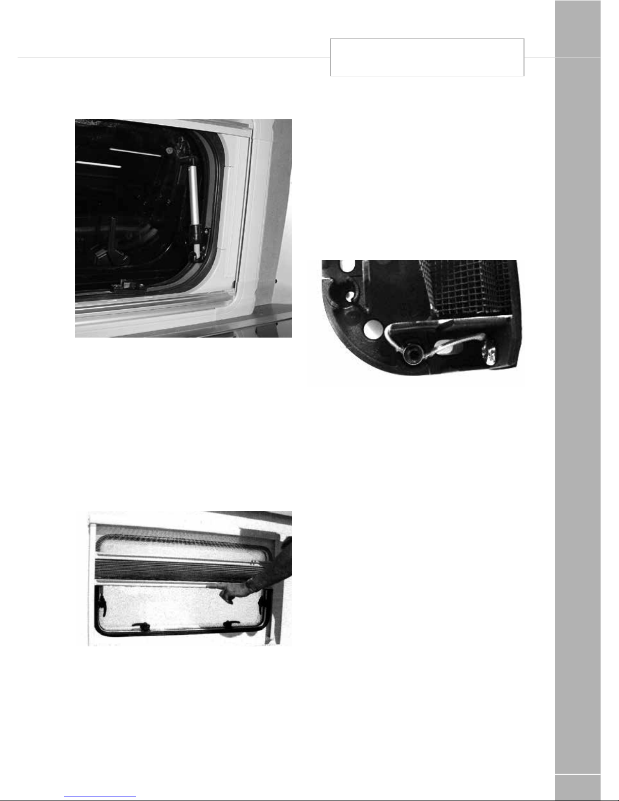
EQUIPMENT DETAILS
133
Windows
To open, turn knobs anti-clockwise and open
catches. Swivel the window pane open to the
desired position and close knobs clockwise to
lock in the open position.
To close, reverse the operation.
All opening windows have two catch positions.
The first position is for ventilation the second
seals the window from ventilation and rain.
Operating instructions for blinds
Closing: Grab the end bar in the middle and
push the blind and flynet together or singly
(blind - lower end bar) downwards until the
required position is reached.
Opening: Push the end bar of the flynet and /
or of the blind upwards.
Care instructions: Clean the blind only with
a damp sponge. Clean on a regular basis to
avoid dirt particle build up as this can damage
the blind material. Use only water or with mild
suds or a vacuum cleaner.
In order to avoid material fatigue, do not leave
the flynet closed for a long time.
To adjust the tension of the Horrex blind:
Trim panels or window surround will need
to be removed before the blind can be
re-tensioned.
In each corner piece there is an cord tensioner
(see photo). By unscrewing the hexagon
screw, the cord can move through the cord
tensioner. When you pull the cord, the tension
will get higher, when you let it move back the
tension will get less.
Roof lights
When opening the roof lights, care must be
taken to release the locking mechanism as the
unit is raised.
Roof lights must be fully closed when
driving. Roof lights provide essential fixed
levels of ventilation.
Mini Heki Rooflight
To open depress button and push bar
upwards. The rooflight has two open
ventilation positions and a fully open position.
The blind and flynet operate independently of
each other and are engaged by connecting to
each other and sliding.
Heki care instructions: Clean the blind only
with a damp sponge. Clean on a regular basis
to avoid dust/ dirt particle build up as this can
damage the blind material. Use only water or
with mild suds or a vacuum cleaner.
WINDOWS / BLINDS
Page 56
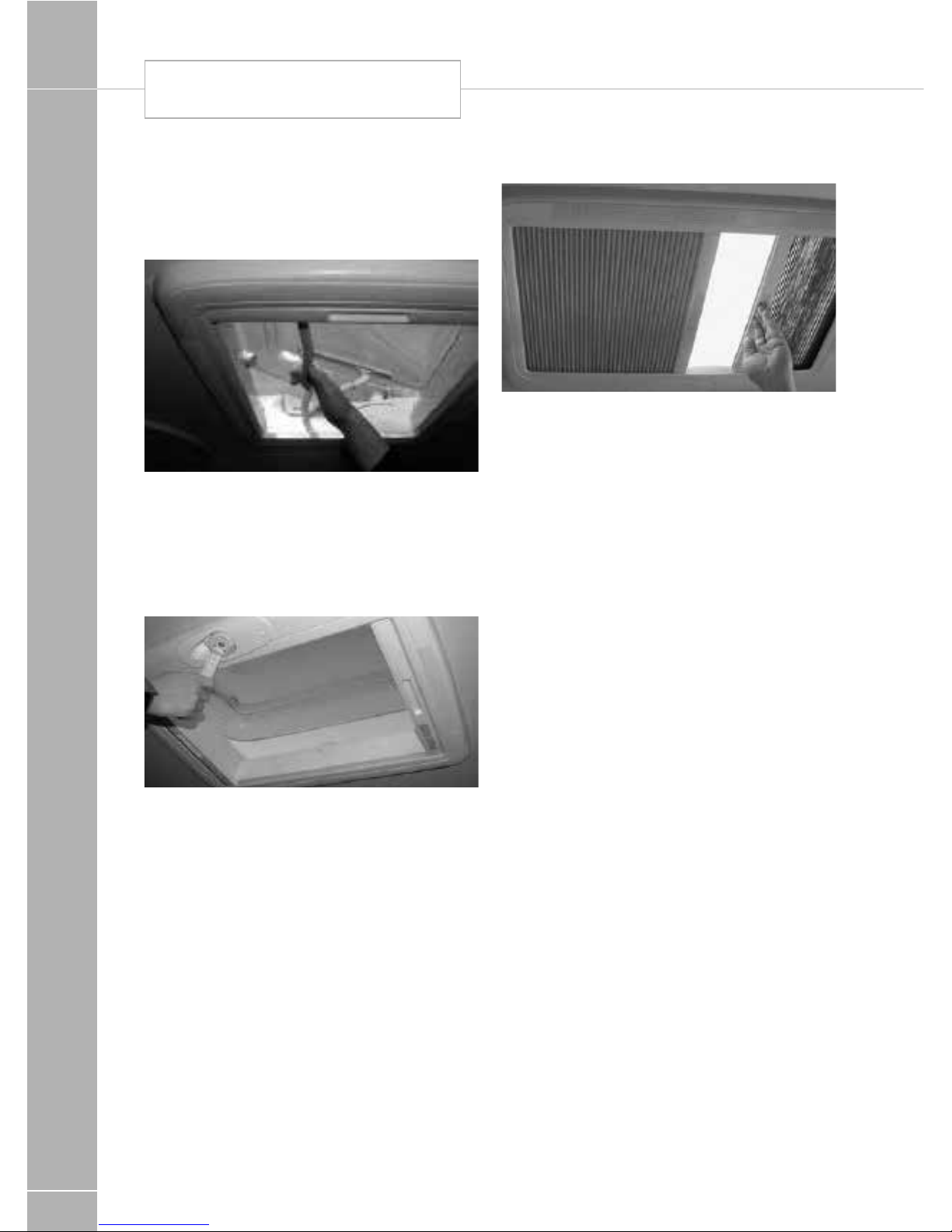
EQUIPMENT DETAILS
134
In order to avoid material fatigue, do not leave
the flynet closed for a long time.
Midi Heki Roof-light
With operating bar: To open, depress button
and push bar to required position. The rooflight
has two open ventilation positions and a fully
open position.
To close, reverse the operation and then check
if locked into position.
With crank: To open, rotate the crank until a
resistance is noticeable during the operation.
To close, reverse the operation and then check
if locked into position.
Blind and Flyscreen
The blind and flyscreen operate Independently
of each other and are engaged by connecting
to each other and sliding.
Safety precautions:
1. Repairs should be carried out only by
trained personnel.
2. Inform an approved dealer in case of
defects and malfunctions.
3. Before starting off, check the rooflight for
damage in the acrylic dome (tension cracks)
and the winding mechanism which could
arise owing to, for example, branches and
other natural causes.
4. Do not step in the acrylic dome.
5. Close the roof light before starting off (check
whether it is locked).
6. Do not leave the vehicle with the rooflight
open (danger of burglary or from rain).
7. Do not open in strong wind or rain.
8. Before opening, remove snow, ice, dirt, etc.
from the acrylic dome.
9. Malfunctions are to be repaired by an
approved dealer at once.
10. Do not use caustic detergents (danger of
tension cracks in the acrylic dome).
11. Do not operate whilst the vehicle is
moving.
MINI HEKI ROOF LIGHT
Page 57

EQUIPMENT DETAILS
135
Care instructions:
• Please clean the acrylic panes with the
Seitz Acrylic Cleaner.
• Stains and light scratches on the acrylic
pane can be removed by using the Seitz
Acrylic Polish and the Seitz special
polishing cloth.
• Use talcum powder (4 times yearly) to care
for the rubber seals
• Clean the blinds only with water and mild
soap suds
• The guarantee becomes null and void if these
instructions are not followed.
Seat swivel (Driver/Passenger)
To turn the swivel, slide the BLACK lever
rearwards and adjust to the required
angle. Before driving off ensure the locking
mechanism is fully secure.
Bunk bed safety
Where the sleeping surface is over one metre
above floor level the following notices apply.
! WARNING: Always ensure safety boards
are located before entering the bunk.
! WARNING: Use upper bunks for
sleeping only, with the provided protection
against fall out in position.
! WARNING: Care shall be taken against
the risk of fall out when the upper bunks are
being used by children, specially under 6
years of age, these bunks are not suitable
for use by infants without supervision
Roof Rack system (Carrera only)
The roof rack system is designed to be
functional and carry a maximum loading of
100kg (or 25kg per mounting foot). Care
should be taken to ensure that the load is
evenly distributed, and that items that could
act as a 'sail' (ie. deck chairs) do not exert
undue stress on the system. Care should be
taken when loading and unloading the roof
rack system.
Side running bars (Where fitted)
The side running bars fitted to the Carerra are
cosmetic and non-functional. They are not
designed to be used as steps or carry any
load. Items should not be secured to them.
Care should be taken to avoid grounding
them and regular cleaning may be required to
maintain the decorative finish.
Omnistep slide-out step
Operation
Press the “step out” key to bring the step out
until it reaches the end of its run or comes up
against an obstacle. The step does not come
out if the engine is running. Press the “step
in” key to take the step back until it reaches
the end of its run or comes up against an
obstacle. The step goes back in automatically
when the engine is running. In this situation the
buzzer sounds until the step is fully closed.
Maintenance
Dirt and frost can prevent the step from
operating properly. In this case the rails and
moving parts should be cleaned or defrosted.
In case of electric break down
If the step does not retract by the motor
• Remove the front plate of the step. (Fig. 1)
• Remove the connection between the
SEAT SWIVEL / BUNK BED SAFETY / ROOF
RACK / OMNISTEP
Page 58
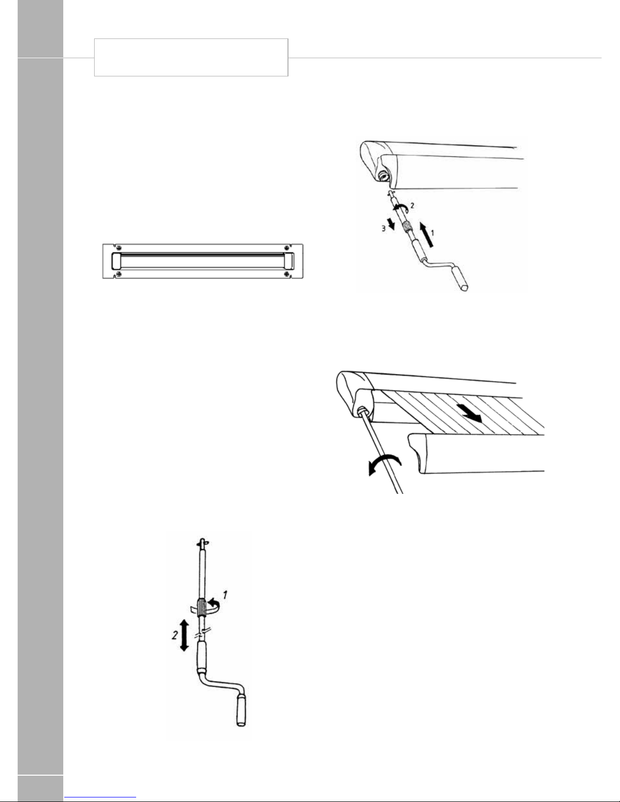
EQUIPMENT DETAILS
136
OMNISTOR AWNING
footboard and the arms (with screwdriver
and wrench S10).
• Slide out the footboard.
• Reinstall the front plate.
Current drawn
• Working current: 5 A
• Blocking current, when fully extended or
retracted: 14 A
Fig. 1 Front plate
Omnistor Awning
General remarks:
• An awning is a sun and not a rain protection.
The awning should be in closed position in
case of storm, snowfall or heavy rainfall.
• The awning can not be used without putting
out the support arms.
• The fabric may not be rolled up wet for a
longer period.
• Clean the awning only by using water or
OMNI CLEANER.
Users instructions:
1. Adjust the crank to the required height.
1
2. Introduce the crank arm into the
bayonet joint.
2
3. Unroll the awning while keeping the crank
down. The awning will only open after a
couple of turnings.
3
Page 59
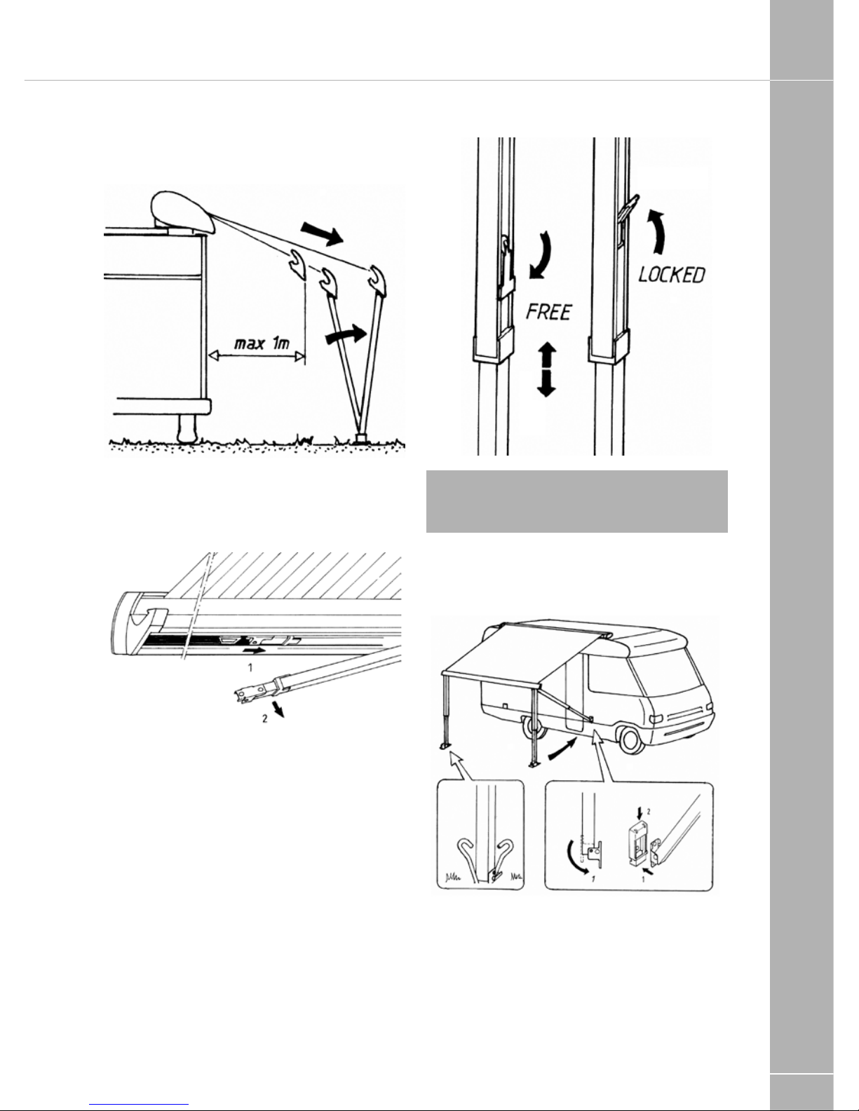
EQUIPMENT DETAILS
137
4. Unroll till 1 m max. Then put out the support
arms before further unrolling
4
5. Slide the support arms out of the
front profile.
5
6. Adjust them to the required height. The
fabric can be tightened by rolling up a little.
6
Note: Never put out the support arms that
high, that the fabric jams between the arms
and the box.
7. Fasten the support arms.
Fig. 7
Page 60

EQUIPMENT DETAILS
138
8. Install the tension rafter (for 3.75 m awning).
8
9. When raining, lower one side of the awning
in such a way that the water can run down
the fabric. Prevent the fabric from flying up
by a sudden wind blow by using the hold
down kit (optional).
9
10. The front profile locks automatically
when rolling up
10
OMNISTOR AWNING
Page 61
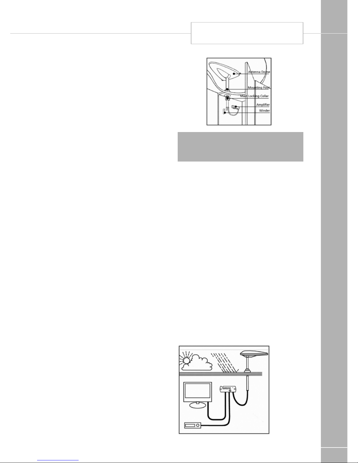
EQUIPMENT DETAILS
139
Status 550 Digital antenna system
Travelling
Do not travel:
• with the antenna raised
• with the antenna set for vertical signals
To reduce the possibility of damage when
travelling, point the antenna backwards.
The RED SPOT on the bottom of the mast
indicates the front of the Antenna.
Operating the system
Firstly determine the approximate location
of the nearest transmitter and whether the
signals are horizontally or vertically polarised.
For assistance ask your site operator or check
other antennas in the vicinity.
1. Loosen the Mast Locking Collar and raise
the antenna. Rotate the mast to direct the
TV transmitter.
The RED SPOT on the bottom of the mast
indicates the front of the antenna.
2. Should you need to receive vertically
polarised signals rotate the winder, anticlockwise to cant the antenna through 90°.
The red / green indicator in the lower part of
the aerial mast indicates whether the aerial
is horizontal or vertical.
DO NOT use undue force on the winder.
3. Switch ON the amplifier and the LED will
illuminate.
4. Check the gain control is set to maximum.
For maximum rotate clockwise.
5. Tune your television into the strongest
signal. You may need to adjust the direction
of the mast to achieve the best picture
quality.
6. Secure by tightening the mast locking collar.
Removing the antenna
1. Unplug the antenna lead from the amplifier.
2. Loosen the mast locking collar and lift off
whilst feeding out the mast, coaxial cable
and plug.
3. Push the blanking cap supplied into place.
! WARNING: The blanking cap is
temporary seal and is not recommended for
long term use.
Technical:
Antenna dome
Length: 530mm
Width: 340mm
Mounting Foot
Diameter: 122mm
Height raised: 330mm
Height lowered: 150mm
No Antenna dome: 50mm
Mast: 365 mm
Amplifier: 115 x 45 x 29mm
Frequency Range: UHF 470-862 MHz
Antenna Forward Gain: 7db
Amplifier Gain - Max: 18db
Gain Adjustment - Min: 15db
Noise Figure: 2.8db
Output Impedence: 75ohms
Output: 98 dbuV
Power Supply: 12-24 VDC
Power Consumption: 55ma
STATUS 550 ANTENNA
Page 62
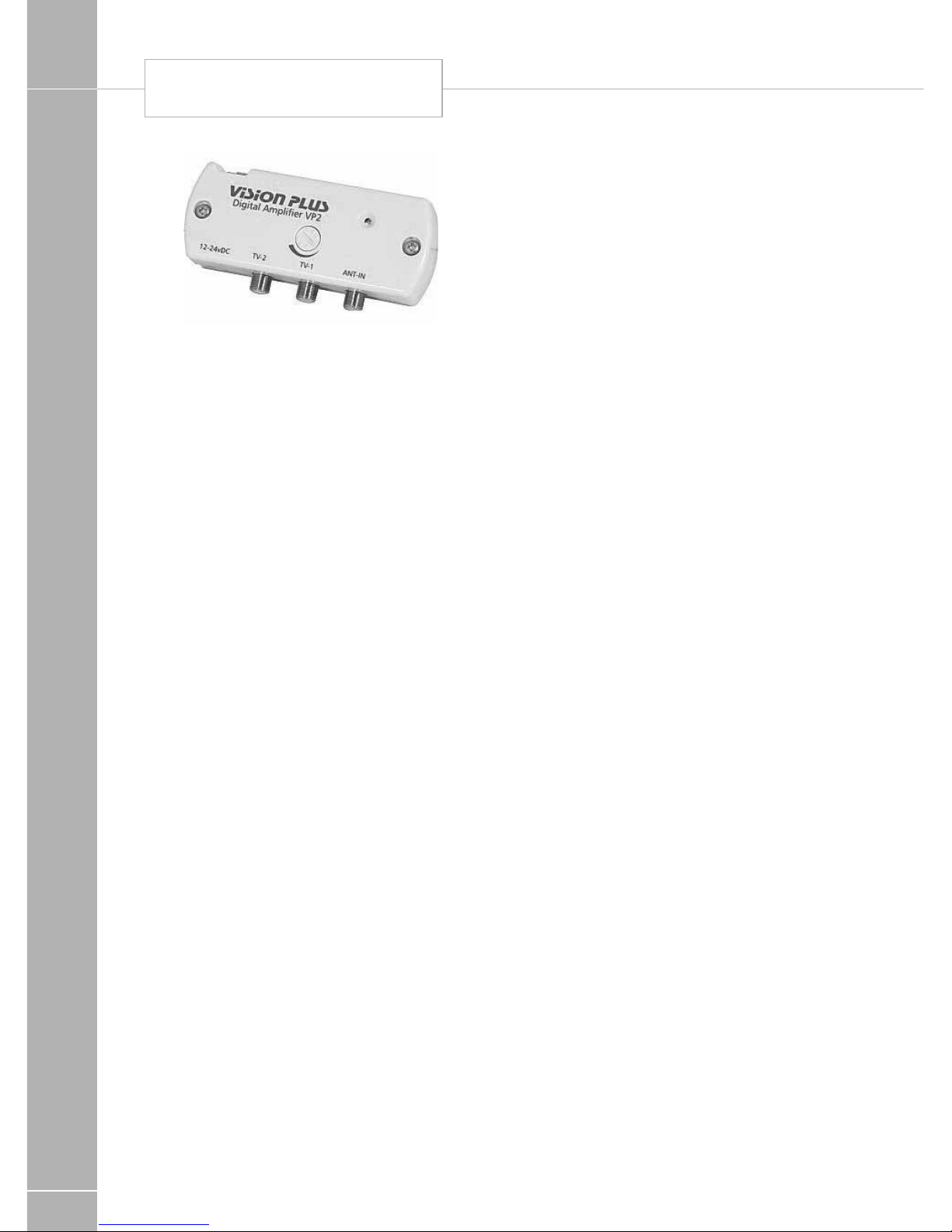
EQUIPMENT DETAILS
140
STATUS 550 ANTENNA
Fault Finding
The following are some of the key areas we
suggest you check which generally solve the
most common problems encountered with the
operation of the Status antenna.
Coaxial Connections
It is critical that all connections in the system
are fitted correctly. Using the diagrams and
procedures described over the page, please
check all connectors ensuring they are wired
correctly. Secondly please ensure only quality
plugs have been used.
Coaxial Cable
Sharp bends, kinks and hot surfaces can
easily damage coaxial cable and should be
avoided. Coaxial cable, if placed in close
proximity to electrical cables, transformers
or other pieces of electrical equipment, may
pick up electrical interference causing picture
quality to deteriorate, especially in poor
reception areas. Excess cable should be
removed and NOT coiled as this may cause
picture distortion. An inspection of the routing
of the cable is highly recommended to ensure
all is correct.
Gain Control
In normal use the button should be rotated
clockwise for maximum. In strong signal areas
the amplification may need to be reduced.
To reduce amplification rotate the button
anti-clockwise until picture quality improves.
The button rotates through 270 degrees from
MAX to MIN.
LED light
Should the LED on the amplifier not light, firstly
check there is power to the unit. Secondly
check the polarity is correct. Otherwise
contact your dealer for further assistance.
Short Hook up - Test 1
This test isolates the wiring from the amplifier
through to your TV/Radio points.
Unplug the coaxial plugs from the 'TV' sockets
of the amplifier and using your TV fly lead with
convertor 1 supplied. Connect your TV to the
amplifier.
Please ensure the antenna dome is plugged
directly into the 'ANT-IN' socket of the
amplifier and switch on. Tune in your TV for the
strongest signal.
If the picture quality improves the fault lies with
the wiring of the system between the amplifier
and the TV outlet socket.
Short Hook up - Test 2
This text isolates the amplifier by connecting
your TV direct to the antenna.
Unplug the antenna from the amplifier and
connect convertor 2 supplied to the plug on
the cable end. Using your TV Fly lead connect
the antenna directly to your TV. Tune in your for
the strongest signal.
If the picture quality improves, the fault lies the
Vision Plus Amplifier.
Antenna Dome Coaxial Cable
Check the routing of the coaxial cable from
the antenna dome to the amplifier. Check to
ensure there are no kinks or trapped cable or
if there are loops of surplus cable which could
be affecting performance.
Page 63

EQUIPMENT DETAILS
141
Signal Symptom Action
Very poor
No picture or
sound, TV freezing, severe pixilation, break up and
picture drop out
Check the amplifier gain is set to maximum
(rotate clockwise). Check antenna alignment
which must be directed at the transmitter.
Ensure the antennas polarity is correct, whether
horizontal or vertical. Bypass the amplifier by
following 'Short Hook-Up Test 1'
Poor
Moderate pixilation
and sound distortion
Medium
Minor pixilation,
will not receive all
channels
Good
Stable picture,
good sound quality, will receive all
channels
N/A
Strong
Moderate pixilation, picture break
up and drop out
Reduce the amplifier gain (rotate anti-clockwise). Rotate antenna AWAY from the transmitter.
Very Strong
No picture or
sound, TV freezing, severe pixilation, break up and
picture drop out
Rotate antenna AWAY from the transmitter.
Switch 'OFF' the amplifier and turn the gain
control to maximum (rotate clockwise).
After performing any of the 'Actions'
above you must re-tune your TV.
Page 64
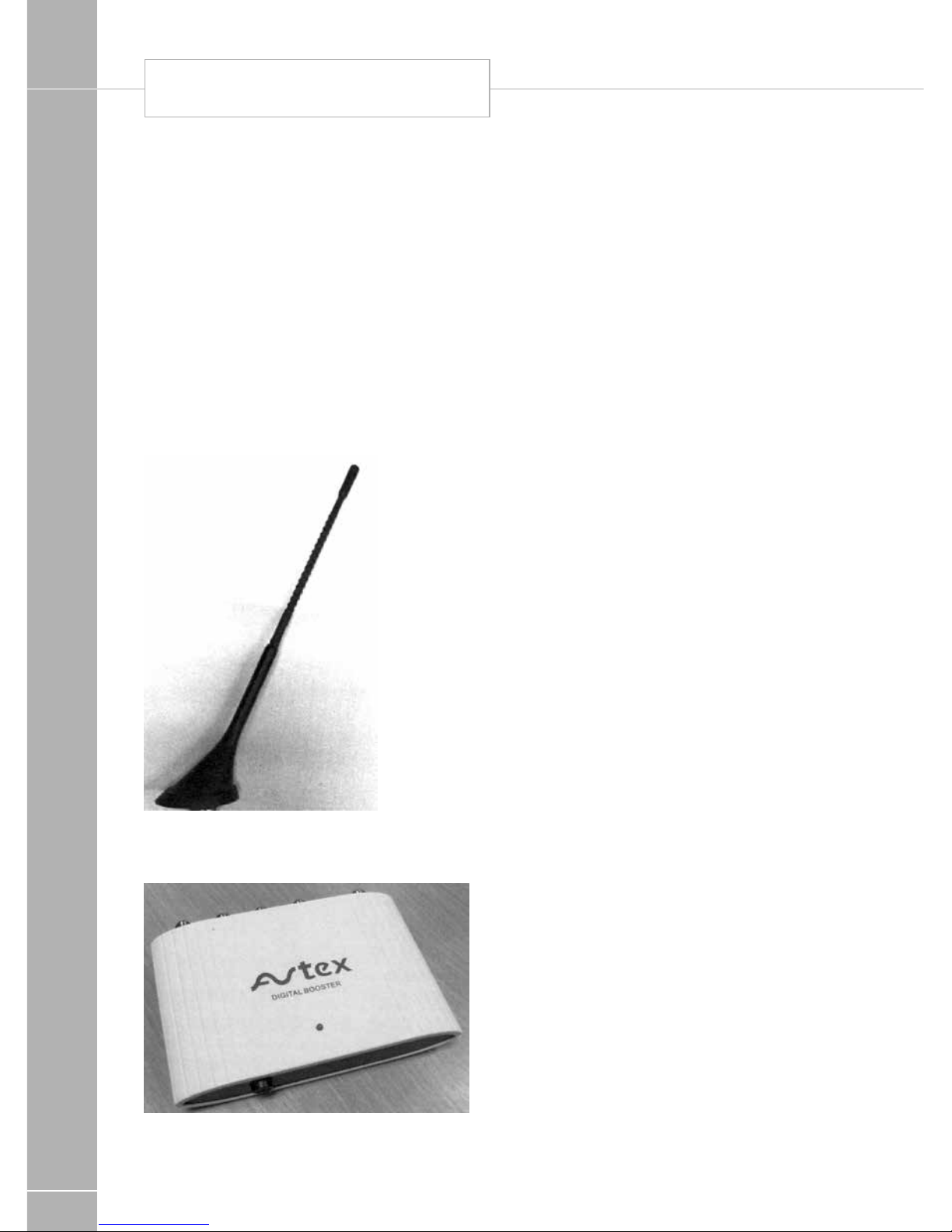
EQUIPMENT DETAILS
142
AVTEX TV AND ANTENNA
Avtex TV and antenna
Depending on the specification of your
motorhome, a supplied television (or
telelvisions) may be present. In addition, an
alternative TV aerial may be fitted in place of
the Status 550 antenna seen on other models.
Avtex DVD
Specifications and functions of televisions are
constantly changing / improving. Please see
the instructions supplied with your television
for the latest information.
Avtex antenna and booster
The Avtex antenna is a fixed antenna on
the roof of the motorhome, and requires no
adjustment in use.
A booster box may also be fitted, linked to
the Avtex antenna. This has a power ON/OFF
switch located on the base of the unit. When
the unit is ON, an LED will illuminate on the
front of the unit.
Care of laminate tops, tables,
furniture and doors
DO NOT use abrasives, chemically treated
cloths or aggressive detergents as these may
cause damage.
DO NOT place hot objects on laminated
surfaces i.e. tops, tables. Any temperatures
70°C and over will cause permanent damage.
Clean worktop surfaces, furniture and door
fascias with a soft, slightly damp cloth, dry off
with a soft cloth.
Furniture doors
During normal travelling, vehicle vibration
and flexing may cause some of the furniture
doors to become out of alignment. For your
convenience many hinges are adjustable.
Table stowage / store in transit
Tables stored in the table storage
compartment must be securely clipped into
place whilst in transit.
To avoid damage care must be taken when
removing tables from their stored position.
Page 65
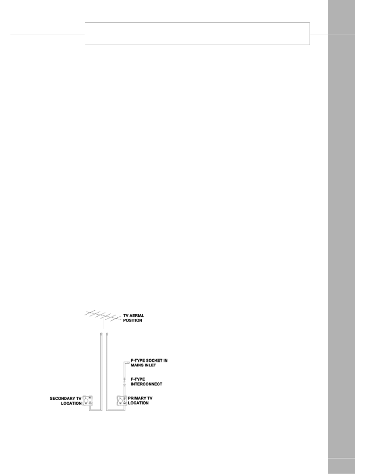
EQUIPMENT DETAILS
143
Shower
When using the shower, always ensure that
the shower door is fully closed thus avoiding
water spray on unprotected areas.
Trigger shower heads
• Squeeze trigger to release water. Release
trigger to top. Twist trigger up to gain
permanent water flow, lower to stop.
• Care should be taken as water may become
hot temporarily when switched on until it
mixes and regulates.
• Small children should be supervised at all
times when using the shower.
• We recommend unfastening the trigger
shower head before travelling and storing
safely to prevent it becoming detached
whilst travelling.
TV inlet
Depending on specification, the motorhome
may be fitted with an external co-ax
connection in place of, or in addition to,
connections for a roof mounted TV aerial. The
external co-ax connection point will be within
the mains inlet enclosure.
Co-ax connection point within the mains
inlet enclosure
A short co-ax lead featuring a screw on co-ax
connection will be present behind the Blue
mains inlet connector. A co-ax cable will be
fitted and connected within the motorhome,
from the back of this connection, to the
primary TV position within the motorhome. At
the same time, further co-ax cable or cables
will be fitted which route from a likely TV aerial
position (i.e. within the wardrobe) to each of
the TV positions within the motorhomes.
The primary TV position will feature a socket
marked 12v, TV, and SAT. The co-ax from
the external connection point will route to the
socket output marked SAT, whilst the co-ax
from the wardrobe or similar will route to the
socket output marked TV. At any secondary
TV positions, if present, the co-ax from the
wardrobe will route to the socket output
marked TV.
An external TV aerial or site TV feed can be
connected to the external connection point;
signals from that connection will then be
available at the primary TV position within the
motorhome. As the connections are of the
screw-on type, it is also possible to use this
co-ax to route from an externally mounted
satellite dish, to a satellite receiver.
Colour reference
The colour code for touch ups or resprays for
all white Fiat/Peugeot cabs and Swift coach
built habitational body components is Fiat
White 249 / Peugeot PØWP. For metallic blue
Fiat 453 / Peugeot MØ4F. For Fiat/Peugeot
cabs other than white, contact your Fiat/
Peuget dealer or obtain a colour match.
Please be aware that colours can fade over
time, and therefore, if the vehicle is more than
a few years old, it is suggested a colour match
be obtained.
SHOWER / TV INLET / COLOUR REFERENCE
Page 66

EQUIPMENT DETAILS
144
EQUIPMENT DETAILS
 Loading...