

Page 1

9
Truma Diagnose Tool
Symbols used
Symbol indicates a possible hazard.
Comment including information and tips.
Table of contents
Symbols used ........................................................................ 9
Safety instructions .......................................................... 10
Interface “Diagnose Tool”
Delivery scope ..................................................................... 10
System requirements .......................................................... 10
Install software .................................................................... 10
Operating voltage ................................................................ 10
Update software ................................................................. 10
LED display .......................................................................... 11
Connection (devices, control systems)
Combi ................................................................................ 11
Control unit installed in the heater ...................................... 11
Export control unit separately ............................................. 12
Mover® ............................................................................... 12
Control unit installed in the vehicle ..................................... 12
Export control unit separately ............................................. 12
Operation instructions (software)
Intended use ........................................................................ 13
User interface ...................................................................... 13
Set language ....................................................................... 13
“Diagnose Tool” program
Start program ...................................................................... 13
Search for device ................................................................ 13
Read error memory ............................................................. 13
Display error list / list of actions .......................................... 14
Save error list ...................................................................... 14
Reset errors ......................................................................... 14
End program ....................................................................... 14
Unlock ................................................................................ 14
Recognition of locked / unlocked control unit .................... 14
“Live Display” program
Start program ...................................................................... 15
Search for device ................................................................ 15
Show error detail ................................................................. 15
Set operating status ............................................................ 15
End program ....................................................................... 15
Page 2
10
Delivery scope
1 Diagnose Tool – interface / hardware
1 CD-ROM with software for
– „Diagnose Tool“
– „Live Display“
1 USB cable
2 Cable – Combi connection (RJ12 – RJ12)
1 Cable – Mover® connection (RJ12 bushing – direct plug)
1 Coupling RJ12 for cable extension
1 Cable (with 5 mm jack on one side) – for the power supply
to the interface via the control unit
System requirements
Windows 2000, XP, Vista, 7 (32 Bit)
Memory required on the hard drive: around 40 MB
(if Microsoft .NET Framework Version 2.0 is not installed,
you will require approximately 275 MB more memory space
on the hard drive)
Install software
Place the CD-ROM into the computer and then follow the
instructions on the screen.
Before the “Diagnose Tool” is connected, the software
needs to be installed on the computer.
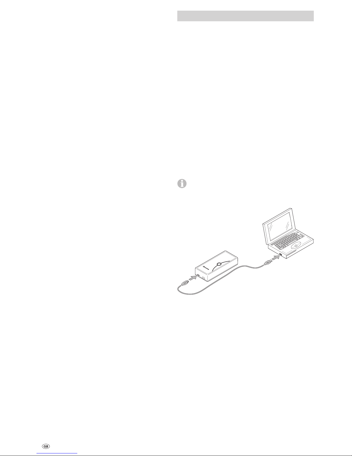
Connect the “Diagnose Tool” to the computer
In
t
er
f
a
ce
1
2
D
i
a
gn
os
e
T
o
o
l
U
S
B
1
2
V
Operating voltage
The interface requires a d.c. voltage of 12 V.
The power is supplied via
the control unit,
or via cable connected to the control unit.
Update software
The current software can be downloaded in the dealer area
(see www.truma.com).
–
–
–
–
–
Interface “Diagnose Tool”
Safety instructions
It may only be operated with original Truma software.
Guarantee claims, warranty claims and acceptance of liability
will be ruled out in the event of the following:
modifications to the unit (including accessories),
modifications to the exhaust duct and the cowl,
failure to use original Truma parts as replacement parts and
accessories,
failure to follow the installation and operating instructions,
changes to the software.
–
–
–
–
–
–
–
Page 3
11
Connection (devices, control systems)
Observe the ESD-regulations!
Combi
Control unit installed in the heater
Room temperature control device at position 1 (= turned all
the way to the left).
Switch on control panel – heating without controlled
water temperature.
Combi 4 (E) / 6 (E): To prevent any malfunctions of the program due to ignition sparks, the “Diagnose Tool” may only be
connected after the device has started.
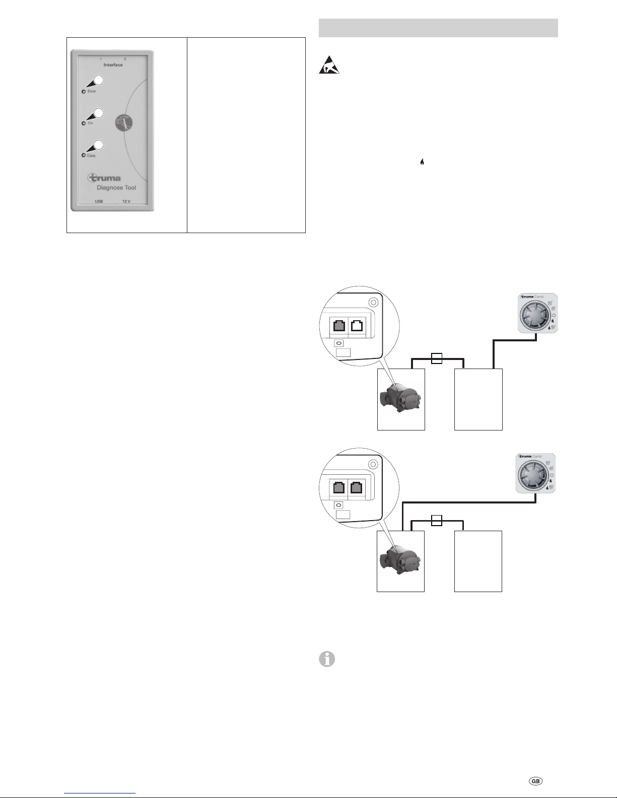
Connect the “Diagnose Tool” to the Combi adapter cable.
Connection to Combi 4 (E) / Combi 6 (E) /
Combi D
X1
Interface
Diagnose ToolCombi
1 2
X1
Interface
Diagnose ToolCombi
1 2
X1 Coupling RJ12 for cable extension
Export error memory
Start the “Diagnose Tool” program on the computer
For Combi 4 E / 6 E, disconnect power selector switch!
–
–
–
–
LED display
2
3
1
1 Error – red LED
Gives the manufacturer
information about the data
traffic.
2 On – green LED
Shines
USB connection and operating voltage available.
Flashes once
(1 Hz) operating voltage
via interface 1(2) missing.
Flashes (1 Hz, 0.5 s off / on)
USB connection missing.
(connect / test cable)
3 Data – yellow LED
Signalises the data transfer
on the bus.
–
–
–
–
–
Page 4
12
Mover®
Control unit installed in the vehicle
The control unit of the Mover® must be operational.
The power supply must be active.
Connect the 13 or 7-pin plugs of the caravan into the safety
socket.
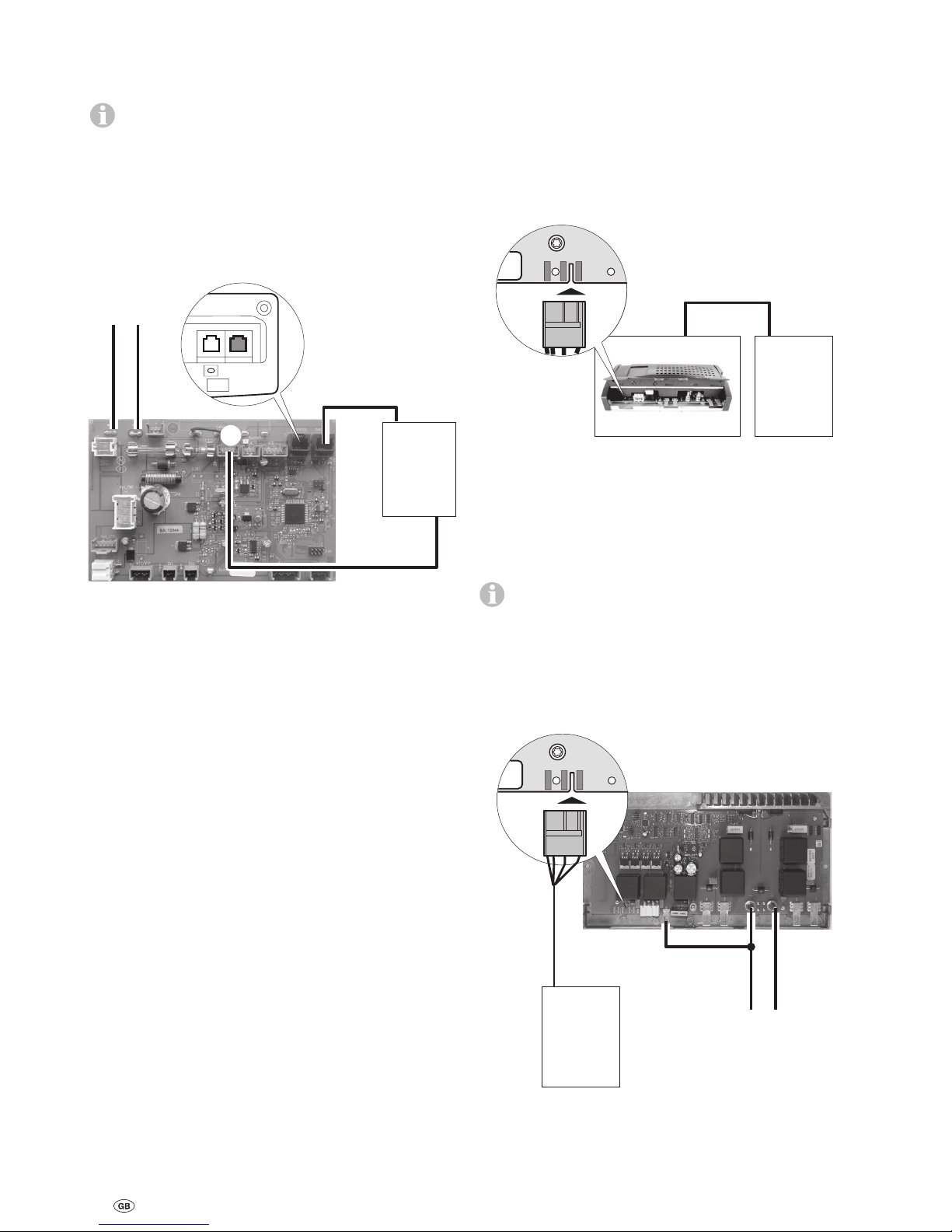
Connect the “Diagnose Tool” to the Mover® adapter cable.
Mover® connection
1 2
Interface
Diagnose ToolMover®
SET/01
belu 2010
Export error memory
Start the “Diagnose Tool” program on the computer.
Export control unit separately
Place the control unit on a non-conductive surface.
Check the wires are connected to the correct terminals.
Operating the control unit without periphery can generate new errors.
Mover® connection
Supply control unit with power (12 V DC / min. 0.2 A)
Simulate the connection of the safety socket with a
bridge (W1).
Connect the “Diagnose Tool” to the Mover® adapter
cable (W2).
+ –
W1
W2
12 V
1 2
Interface
Diagnose Tool
SET/01
belu 2010
Export error memory
Start the “Diagnose Tool” program on the computer.
–
–
–
–
–
–
–
–
–
–
–
Export control unit separately
Place the control unit on a non-conductive surface.
Check the wires are connected to the correct terminals.
Operating the control unit without a sensor and cable
harness can generate new errors (Combi 4 / 6 – No. 61,
Combi D – No. 111).
Connection to Combi 4 (E) / Combi 6 (E) /
Combi D
Supply control unit with power 12 V DC / min. 0.2 A
also supply the „Diagnose Tool“ with power via the control
unit (12 V DC / min. 0.2 A).
+ –
Interface
12 V DC /
min. 0,2 A
Diagnose Tool
1 2
12 V
X2
X2 connection to clock – Combi 4 (E) / Combi 6 (E)
connection to ZSU – Combi D
Export error memory
Start the “Diagnose Tool” program on the computer.
–
–
–
–
–
Page 5
13
Intended use
This software can show or change the operating statuses or
parameters for TIN-cable devices. Error protocols can be created, exported or the error memory can be deleted. Locked
electronics can be unlocked as required.
User interface
The programs are operated with a mouse. Values are entered
using the keyboard.
Set language
1
1 Open the “Tools”
menu and click
“Language” to select
the menu language.
Operation instructions (software)
“Diagnose Tool” program
Prerequisites for operation:
Device from index
Combi 4 (E)
Combi 6 (E)
4/12A 6/12A
4/11 6/11
4/12 6/12
4/13 6/13
Combi D 6/06 6/07 4/01
Mover® all (Mover® S from 01/2008)
Start program
The “Live Display” program may not be active, it must be
closed first.
1
Diagnose Tool
2
1 Double-click the icon
on the desktop.
2. A start screen is shown
whilst the program is
loading.
Search for device
1
1 Open the “Tools”
menu and click “Start”
to start the search.
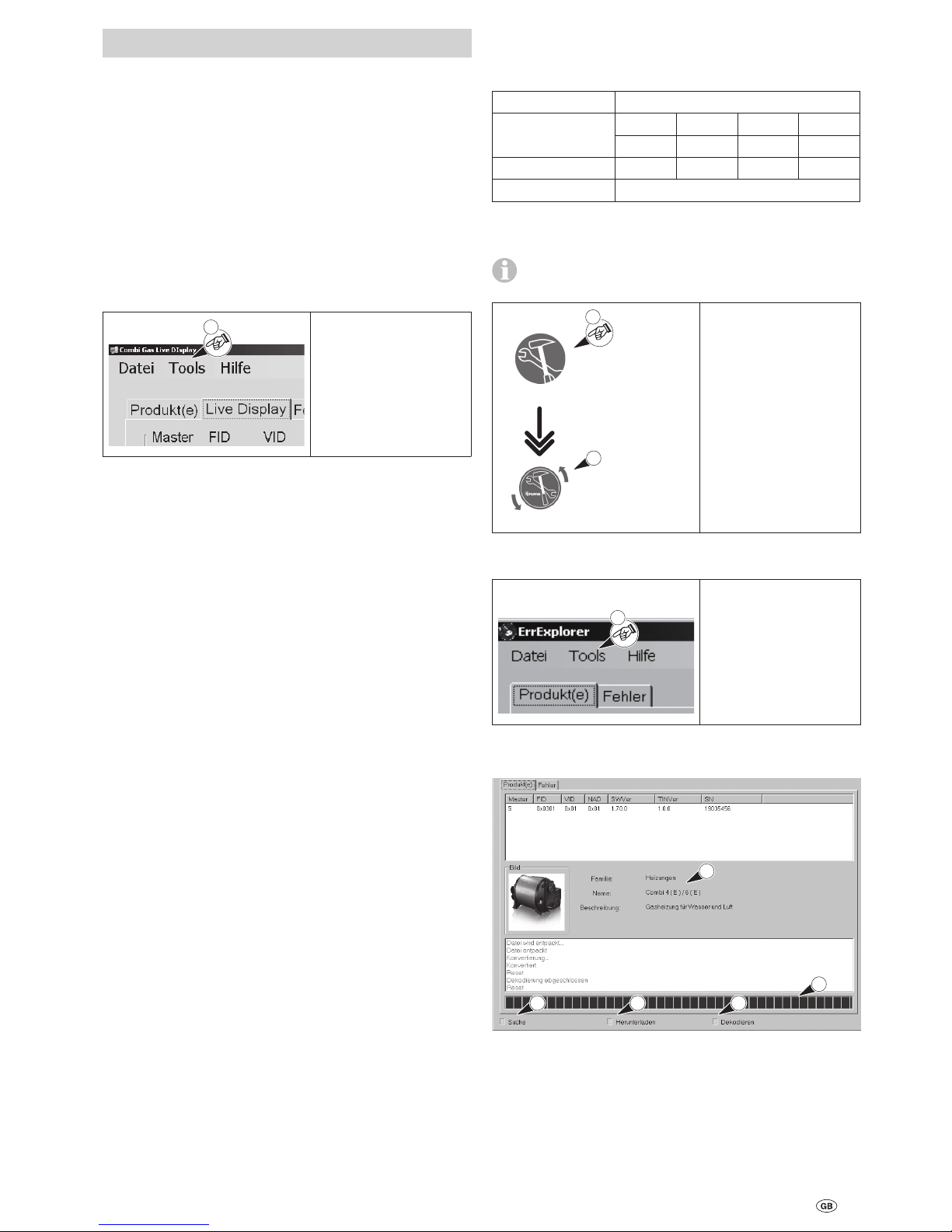
Read error memory
2 3
4
1
5
Display the current action
1 Device search.
2 The error memory is exported.
3 The content of the error memory is prepared for display.
4 Status bar.
5 Device for which an error was exported.
Page 6
14
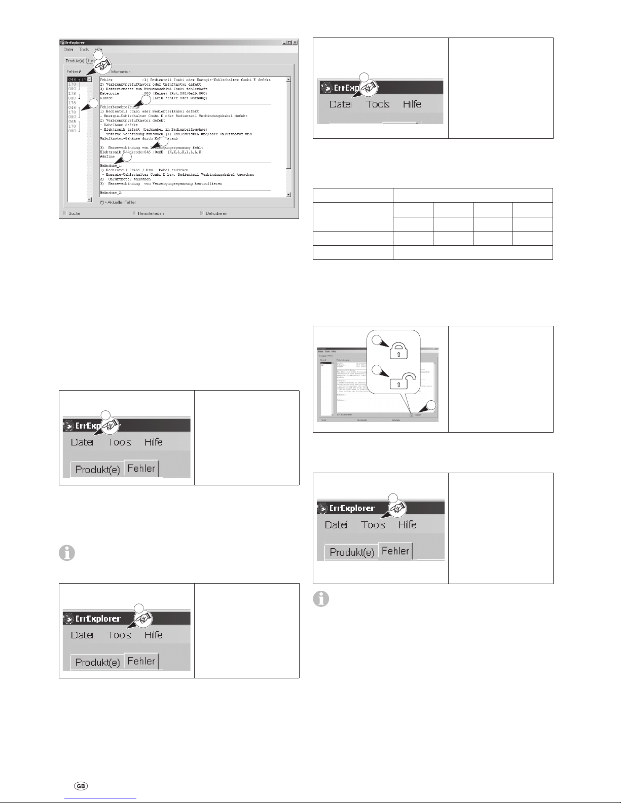
Display error list / list of actions
2
3
4
1
5
1 Error list
The current error is marked with (*). If there is no (*), the
current error is undefined.
Display list of measures by clicking an error.
2 Error description
3 Flash code
4 One or several measures to rectify the error
5 Group error with “
]” – meaning depending on test object.
Combi – Simultaneous occurrence of errors within
a data package.
Mover® – The same error occurred several times in sequence.
Save error list
The error list can be saved to communicate with Truma.
1
1 Click the “File” menu
and select “Save at”.
Accept or change
<file name>.
Click “Save”.
–
–
<File name>.tef – .tef. = expansion of the file name for the
binary error protocol.
Reset errors
The menu item “Reset errors” is only active if the error
list has been filed beforehand in the file system with
“Save error list”.
1
1 Click the dialogue
“Tools” and select
“Reset errors”.
The error memory in
the device is reset
(deleted).
–
–
End program
1
1 Open the menu “File”
and leave the program
by pressing “End”.
Disconnect the diagnosis cable from the
test object.
Switch device off.
–
–
Unlock
Prerequisites for operation:
Device from index
Combi 4 (E)
Combi 6 (E)
4/12A 6/12A
4/11 6/11
4/12 6/12
4/13 6/13
Combi D 6/07 4/01
Mover® –
Recognition of locked / unlocked control unit
A locked / unlocked control unit is marked by a symbol
and text.
1
2
3
1 Symbol for a locked
control unit.
2 Symbol for an unlocked
control unit.
3 Text
So that the device can be unlocked, the previously specified
work steps need to be observed.
1
1 Click the menu “Tools”
and select “Unlock”.
A checklist with work
instructions is shown.
Work through the
checklist and confirm.
Click “Unlock”.
–
–
–
The unlock function does not delete the error memory.
Delete the entries in the error memory with “Reset errors”.
Page 7
15
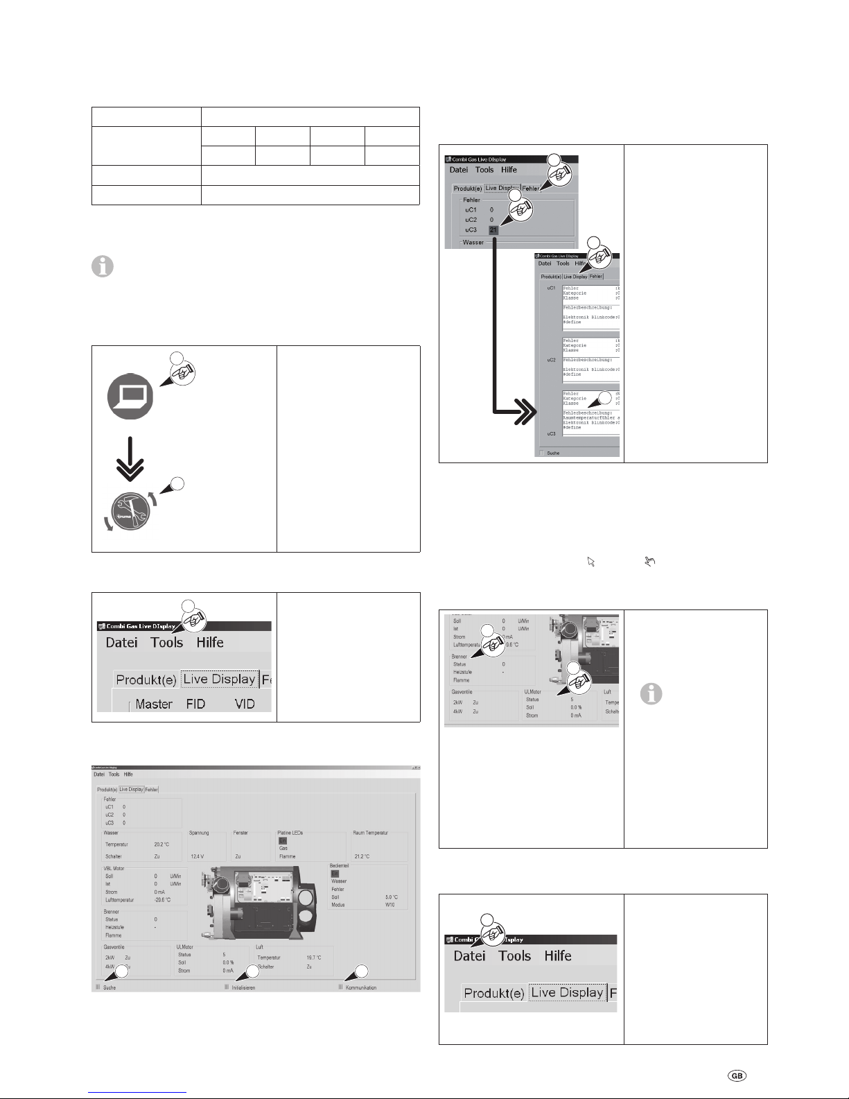
3 Communication between the PC and the device.
– Field flashes green – faulty communication.
– Field shines red – interruption.
Show error detail
Any errors are marked in red on the screen.
1
4
3
2
1 Show the error details
by clicking the field
marked in red.
or
2 Show the error details
by clicking the “Error”
tab.
3 Detailed description of
the error.
4 Return to the
“Live Display” program by clicking the
“Live Display” tab.
Set operating status
Certain operating parameters can be set for examinations.
For the Combi 4 (E) / Combi 6 (E) devices this is e.g. the field
“Burner” or “ULMotor”. If the cursor is moved over this field,
the cursor changes from an arrow to a hand.
Combi 4 (E) / Combi 6 (E)
1
2
1 Click the field
“Burner” to change
the parameters of the
burner.
Set the speed of
the “ULMotor”
(D.C motor) to min.
25 % otherwise the
heater may cut out
due to overheating.
or
2 Click the field
“ULMotor” to change
the parameters of the
D.C. motor.
End program
1
1 Open the menu “File”
and leave the program
by pressing “End”.
Disconnect the diagnosis cable from the
test object.
Switch device off.
–
–
“Live Display” program
Show or change the operating statuses and parameters
Prerequisites for operation:
Device from index
Combi 4 (E)
Combi 6 (E)
4/12A 6/12A
4/11 6/11
4/12 6/12
4/13 6/13
Combi D –
Mover® –
Start program
The “Diagnose Tool” program may not be active, it
must be closed first.
Combi 4 (E), 6 (E): Operate the device in heating mode with
the D.C. motor due to overheating. To do this, set the rotary
knob for the room temperature to “5” on the control panel.
1
Combi Live Display
2
1 Double-click the icon
on the desktop.
or
2 A start screen is shown
whilst the program is
loading.
Search for device
1
1 Open the “Tools”
menu and click “Start”
to start the search.
After a successful search, this screen is shown with parameters in the case of a Combi.
2
3
1
Display the current action
1 Device search.
2 Initialisation of the hardware and software.
Page 8

16
Truma Diagnose Tool
Symboles utilisés
Ce symbole indique des risques possibles.
Informations et conseils.
Table des matières
Symboles utilisés ................................................................ 16
Informations concernant la sécurité ............................. 17
Interface « Diagnose Tool »
Fourniture ............................................................................ 17
Conditions du système ........................................................ 17
Installer le logiciel ................................................................ 17
Tension de service ............................................................... 17
Mettre le logiciel à jour ....................................................... 17
Affichage DEL ..................................................................... 18
Raccordement (appareils, commandes)
Combi ................................................................................ 18
Commande installée dans le chauffage .............................. 18
Consulter séparément la commande .................................. 19
Mover® ............................................................................... 19
Commande installée dans le véhicule ................................. 19
Consulter séparément la commande .................................. 19
Mode d‘emploi (logiciel)
Utilisation ............................................................................ 20
Interface utilisateur ............................................................. 20
Régler la langue ................................................................... 20
Programme « Diagnose Tool
»
Démarrer le programme ..................................................... 20
Chercher l‘appareil .............................................................. 20
Consulter la mémoire d‘erreurs .......................................... 20
Afficher liste des erreurs / liste des mesures ...................... 21
Enregistrer la liste des erreurs ............................................ 21
Réinitialisation des erreurs .................................................. 21
Terminer le programme ....................................................... 21
Déverrouillage ................................................................... 21
Identifier la commande verrouillée / déverrouillée .............. 21
Programme « Live Display
»
Démarrer le programme ..................................................... 22
Chercher l‘appareil .............................................................. 22
Afficher les détails de l‘erreur ............................................. 22
Régler l‘état d‘exécution ..................................................... 22
Terminer le programme ....................................................... 22
 Loading...