

Page 1
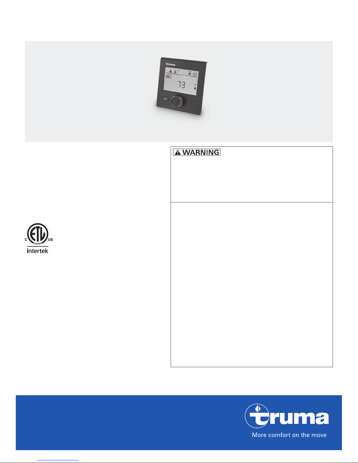
Truma CP plus VarioHeat
Digital control panel
FIRE OR EXPLOSION HAZARD
Operating instructions Page 2
Installation instructions Page 16
To be kept in the vehicle.
This document is part of the product.
4010007
Failure to follow safety warnings exactly
could result in serious injury, death or property damage.
Do not store or use gasoline or other flammable vapors and liquids in the vicinity of
this or any other appliance.
WHAT TO DO IF YOU SMELL GAS
• Evacuate all persons from the vehicle.
• Shut off the gas supply at the gas container or source.
• Do not touch any electrical switch or use
any phone or radio in the vehicle.
• Do not start the vehicle’s engine or electric
generator.
• Contact the nearest gas supplier or certified service technician for repairs.
• If you cannot reach a gas supplier or certified service technician, contact the nearest
fire department.
• Do not turn on the gas supply until gas
leaks have been repaired.
Installation and service must be performed
by a certified service technician, service
agency, or the gas supplier.
Page 2

Table of contents
Intended use .......................................................................... 2
Consumer Safety Information
Safety Definitions ..................................................................... 3
Safety Behavior and Practices .................................................. 3
California Proposition 65 lists chemical substances known to the state to cause cancer,
birth defects, death, serious illness or other
reproductive harm. This product may contain
such substances.
Trademark information
Operating Instructions
Display and Operating Elements ........................................ 4
Description ............................................................................... 4
Rotary push button ................................................................... 4
Back button .............................................................................. 4
Instructions for use ................................................................... 4
Initial start-up ........................................................................... 5
Start-up ..................................................................................... 5
Functions .................................................................................. 5
Selecting the setting level ........................................................ 5
Switching on / off ..................................................................... 5
Changing the room temperature .............................................. 5
Selecting the fan speed ............................................................ 6
Change hot water mode .......................................................... 7
Setting the time switch ............................................................ 7
Set clock ................................................................................... 9
Service menu ............................................................................ 9
Special displays ...................................................................... 10
Warning / Error .................................................................... 11
Warning .................................................................................. 11
Maintenance ........................................................................ 12
Technical data ...................................................................... 12
Troubleshooting chart VarioHeat (H) ............................... 13
Troubleshooting chart AquaGo (W) ................................. 14
Truma CP plus VarioHeat reffered to as
CPplusVarioHeat below.
Truma AquaGo reffered to as AquaGo below.
Truma VarioHeat comfort US reffered to as
VarioHeat below.
Intended use
The CPplusVarioHeat control panel is suitable
only for installation in RVs used for recreation,
travel, or camping.
• The CPplusVarioHeat control panel controls
and monitors a VarioHeat and/or AquaGo.
Installation instructions
Safety Information .................................................................. 16
Description ............................................................................. 16
Dimensions ............................................................................. 16
Installation location ................................................................ 16
Wiring diagram ....................................................................... 17
Connection ............................................................................. 17
Installation .............................................................................. 18
2
Page 3
Consumer Safety Information
Safety Definitions
This is the safety alert symbol. This symbol
alerts you to potential hazards that can kill or
hurt you and others.
indicates a hazardous situation
which, if not avoided, could result in death or
serious injury.
is used to address practices not re-
lated to physical injury.
Other important information or tips.
Safety Behavior and Practices
• Use the CPplusVarioHeat control panel
only when it is in a technically sound
condition.
• Have a specialist immediately remedy any
malfunctions. Remedy the malfunction
yourself only if a remedy is specified in the
troubleshooting chart in these operating
instructions.
• Have a defective CPplusVarioHeat control
panel repaired only by the manufacturer or
its service department.
• Any alteration to the appliance or its controls can be dangerous and will void the
warranty.
• Switch OFF the VarioHeat furnace and/or
AquaGo when refueling, pumping gas or
when the recreational vehicle (RV) is in a
parking garage, on a ferry, or in enclosed
spaces (such as a garage, repair shop).
Make absolutely sure that the VarioHeat
furnace and/or AquaGo cannot be switched
on via the time switch. To do this, you have
to switch the CPplusVarioHeat control
panel off or interrupt the power supply to
the control panel.
3
Page 4
Operating Instructions
+
-
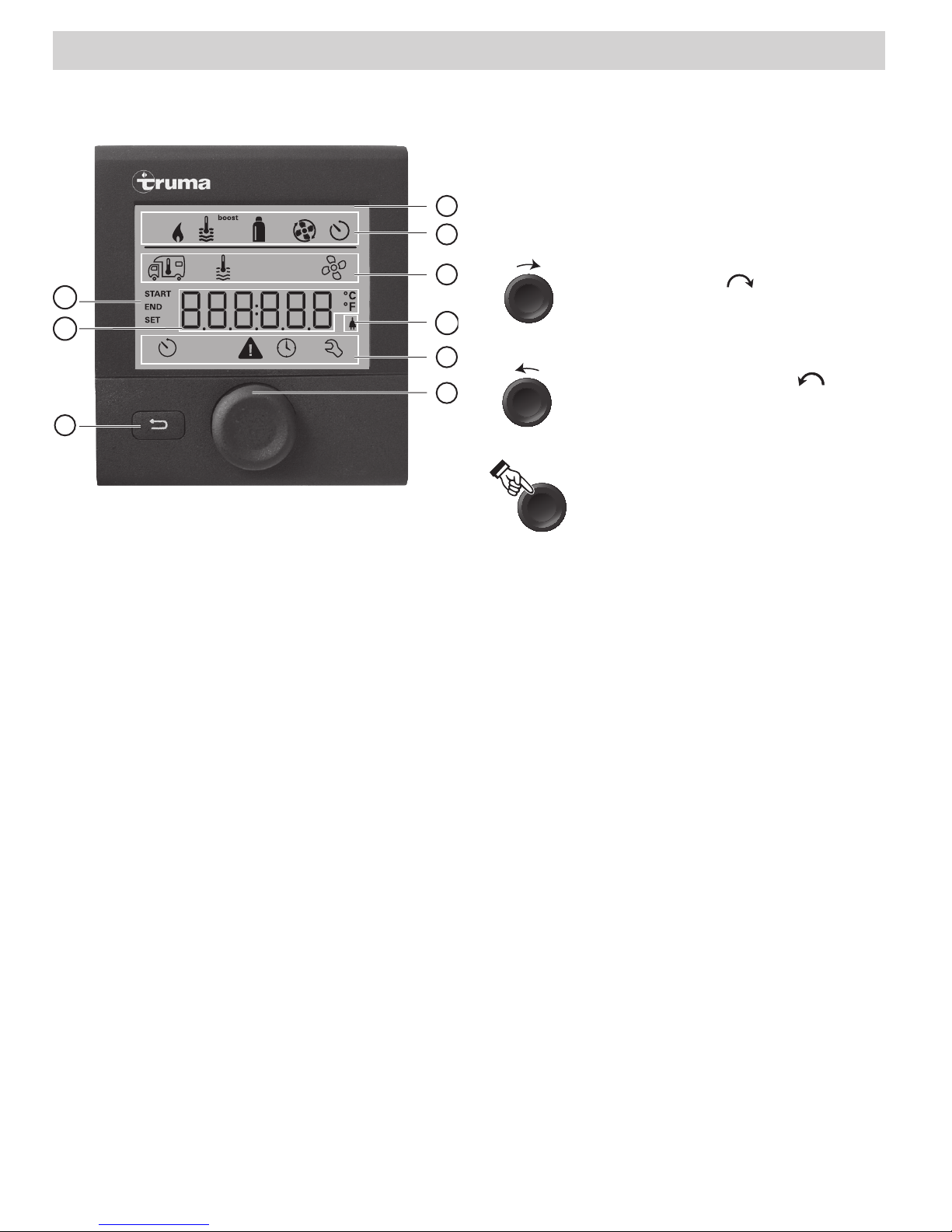
Display and Operating Elements Rotary push button
The rotary push button(8) is used to select and
change setpoints and parameters; it is then
tapped to save the values. Selected menu items
1
hot
eco
flash.
2
6
7
9
Fig. 1
1 Display
2 Status line
3 Menu line (top)
4 Menu line (bottom)
5 Power supply display
120VAC (mains supply)
6 Time switch display
7 Settings/Values
8 Rotary push button
9 Back button
3
Turn clockwise
• The menu is scrolled through
5
from left to right
• Increase values (+)
4
8
Turn counterclockwise
• The menu is scrolled through
from right to left
• Reduce values (-)
Ta p
• Save a selected value
• Select a menu item, go to the
setting level
Press and hold
• Main switching function – control panel on/off.
Back button
Press the Back button(9) to go back to a previous menu and cancel settings. This means that
the previous values remain unchanged.
Description
• A rotary push button (8) is used to select
menu items in the menu lines (3 + 4) and to
adjust settings.
• Information is shown on a backlit display(1).
• The Back button(9) is used to go back to a
previous menu.
4
Instructions for use
• If there is an interruption to the power supply, the clock has to be reset.
• If a new furnace is connected to the bus system of the control panel, repeat the procedure described in “Initial start-up”.
Page 5
Initial start-up
Selecting the setting level
Perform the following steps for initial start-up:
1. Switch on the power supply.
– 12 V DC for the CPplusVarioHeat control
panel and VarioHeat heater
2. Start searching for the appliances in the
menu item “Service menu” –> “RESET” –>
“PR SET”.
When you have confirmed the selection, the
CPplusVarioHeat control panel is initialized.
“INIT ..” appears on the display while this is in
progress. This stores the devices that have been
found in the control panel.
Start-up
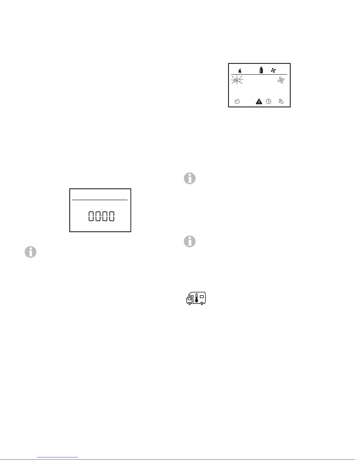
Start / Stand-by screen
When the Truma CPplusVarioHeat control
panel is connected to the power supply, a start
screen is displayed after a few seconds.
• Tap the rotary push button.
The display shows the setting level. The first
icon flashes.
Fig. 3
Switching on / off
Switching on
• Tap the rotary push button.
Previously set values and operating parameters are active again when the panel
is switched on.
Fig. 2
• The display alternates between the current time and the room temperature
that you set.
• Special displays on command via
CI-BUS (refer to “Special displays” on
page).
• After repairs or upgrades, “initial startup” has to be repeated.
Functions
The functions of menu lines (Fig.1–3,4) of the
Truma CPplusVarioHeat control panel can be
selected in any sequence. The operating parameters are shown in the status line (Fig.1–2) or
in the display (Fig.1–6).
Switching off
• Press the rotary push button for more than
4seconds.
The switching off process of the TrumaCPplusVarioHeat control panel may
take a few minutes due to internal time
lags of the VarioHeat or the Truma AquaGo
(“OFF” is displayed during this time).
Changing the room
temperature
1. Use the rotary push button to select the icon
in the menu line (Fig.4–3).
2. Tap the rotary push button to go to the setting level.
3. Use the rotary push button to select the
heater (HEATER).
4. Tap the rotary push button to confirm the
selection.
5. Select the desired temperature with the rotary push button.
6. Tap the rotary push button to confirm the
value.
5
Page 6
3
a
2
3
a b c d
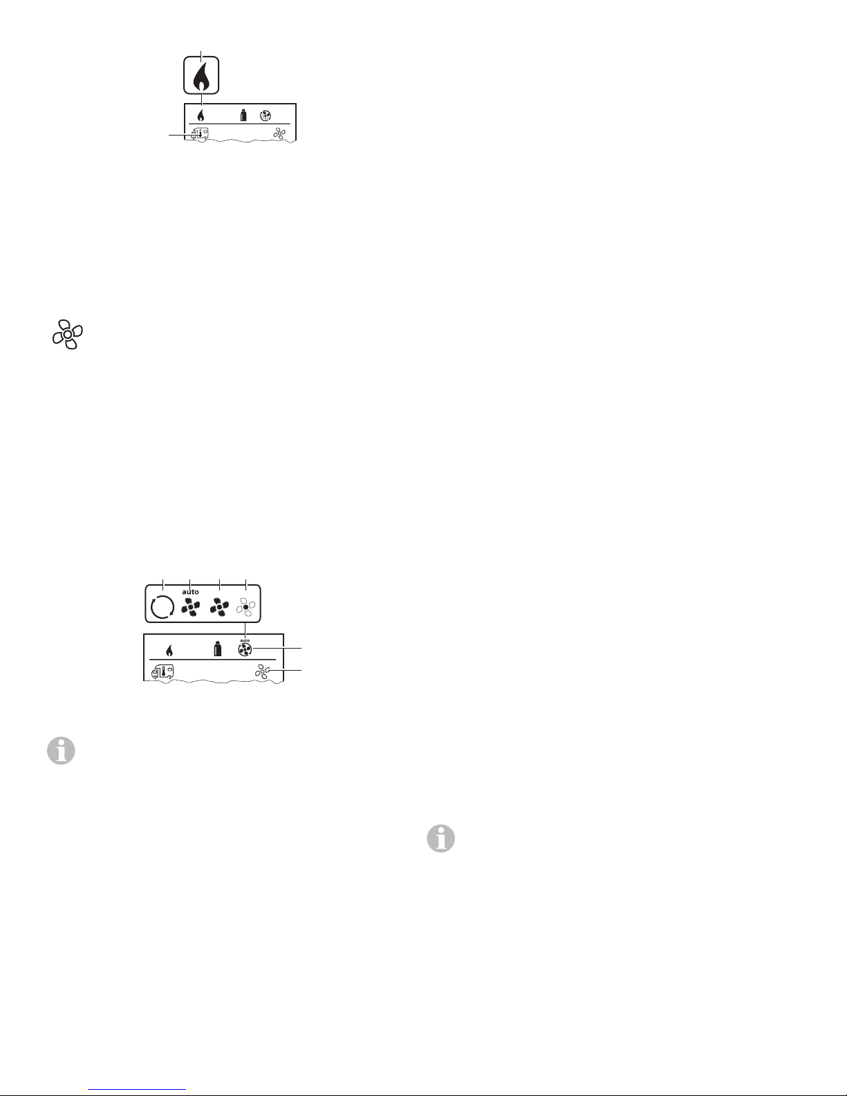
Heater (HEATER)
Fig. 4
Heater (HEATER)
Adjustable temperature range 40 – 86 °F
(1°Fincrements) or 5 – 30 °C (1°C increments)
a = Heater on – icon is lit;
the icon flashes until the room
temperature is reached.
Selecting the fan speed
With a heater connected
1. Use the rotary push button to select the icon
in the menu line (Fig.5–3).
2. Tap the rotary push button to go to the setting level.
3. Select the desired fan speed with the rotary
push button.
4. Tap the rotary push button to confirm the
value.
Icon Operating
Description
mode
– OFF Fan is switched off.
(Can be selected
only if no appliance is
running.)
a VENT
1
Circulating air, if no
appliance is running.
Speed can be selected
in 10increments.
b AUTO Automatic fan control
depending on the heating output / optimized
to the current heating
requirements
2
c BOOST
Fast room heating
Available if the difference between the
selected and the current room temperature is greater than
50°F(10°C).
d NIGHT Ultra-quiet fan opera-
tion. Heater runs only
on part load; the set
room temperature may
not be reached (depending on the size of the
vehicle and the outdoor
temperature).
Fig. 5
The temperature range below 41 °F (5°C;
OFF) must be selected in order to switch
off the heater.
6
1
Can increase wear and tear on the motor,
depending on how often it is used.
2
“BOOST” fan speed uses more electricity,
is louder, and increases wear and tear on the
motor.
When the heater is switched on (room temperature set), the fan speed selected in the
previous heating process is shown in the
status line(Fig.1–2). The default setting is
“AUTO”.
Page 7
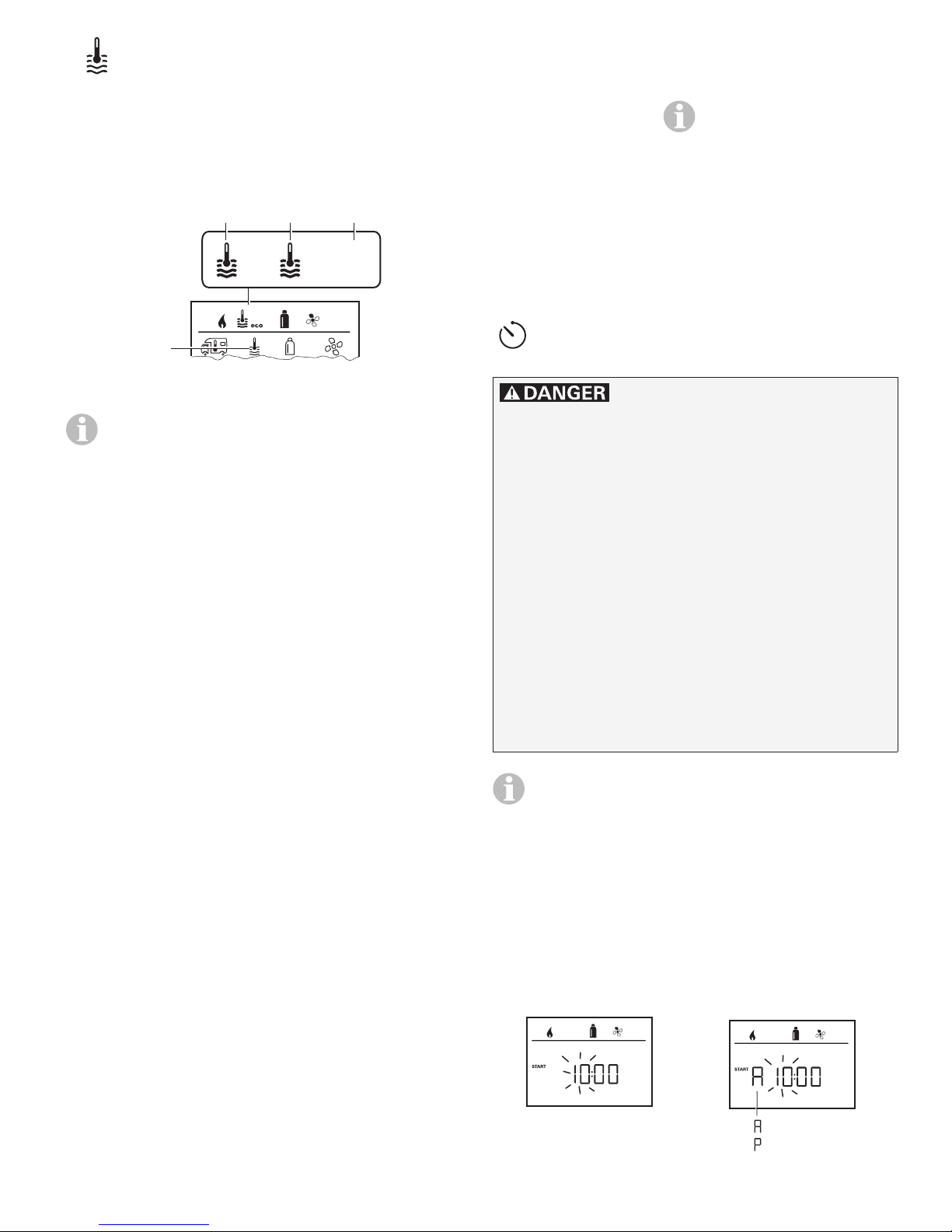
Change hot water mode
= p. m.
c ANTIFR Prevention of freezing us-
ing 12 VDC electricity:
1. Use the rotary push button to select the icon
in the menu line (Fig.6–3).
2. Tap the rotary push button to go to the setting level.
a b c
eco eco
3
Fig. 6
If the warning “CLEAN” is displayed, the
AquaGo must be decalcified
(see “2.2 CLEAN” page 9).
3. Select the desired hot water mode with the
rotary push button.
4. Tap the rotary push button to confirm the
selection.
5. Select the desired hot water temperature
with the rotary push button 95-120°F
(35-49 °C).
6. Tap the rotary push button to confirm the
value.
Operating mode with
installed electric antifreeze kit (available as an
accessory) and appliance
switched on. The temperature in the appliance is
automatically kept above
41°F (5 °C).
During operation, the icon
is flashing.
Setting the time switch
Risk of carbon monoxide poisoning.
The enabled time switch switches the heater
on, even when the recreational vehicle (RV) is
parked. The exhaust gas from the heater can
cause poisoning in enclosed spaces (e.g. garages, repair shops).
If you park the RV in an enclosed space:
1. Block the fuel supply (gas) to the heater.
2. Disable the time switch of the
CPplusVarioHeat control panel (OFF).
Hot water mode
Icon Operating
Description
mode
– OFF AquaGo is switched off.
a ECO The AquaGo is now run-
ning in energy-saving
mode.
b COMFOR The AquaGo is now run-
ning in a mode that provides rapid availability of
hot water.
3. Switch off the heater on the
CPplusVarioHeat control panel.
If the time switch is ON, the “Disable time
switch (OFF)” menu is displayed.
1. Use the rotary push button to select the icon
in the menu line (Fig.1–4).
2. Tap the rotary push button to go to the setting level.
Enter the start time
Use the rotary push button to set the hours and
then the minutes.
24h mode 12h mode
= a. m.
Fig. 7
Fig. 8
7
Page 8
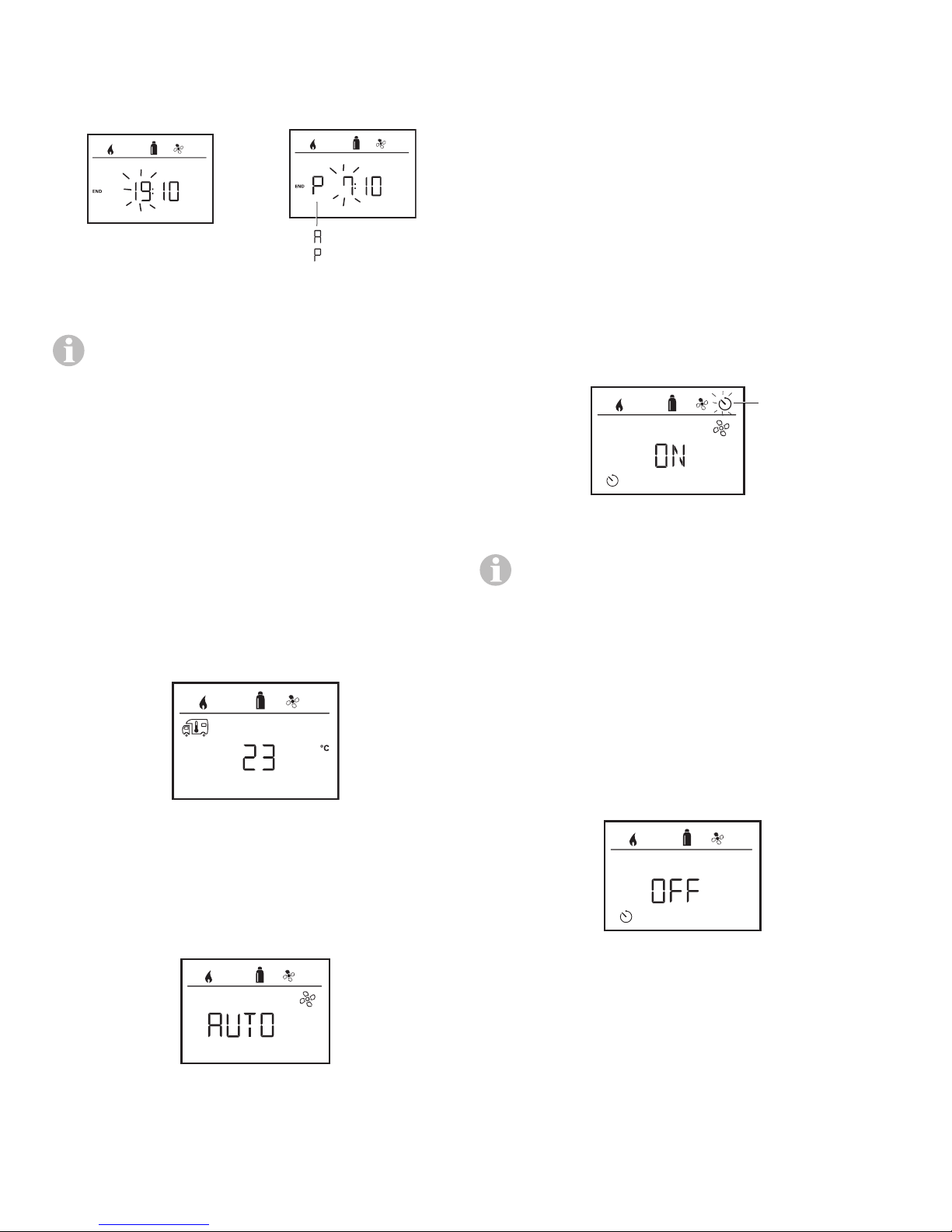
Enter the end time
= p. m.
2
Use the rotary push button to set the hours and
then the minutes.
24h mode 12h mode
= a. m.
Selecting the hot water temperature
1. Select the desired hot water mode with the
rotary push button.
2. Tap the rotary push button to confirm the
selection.
3. Select the desired hot water temperature
with the rotary push button 95-120°F
(1°Fincrements) or 35-49 °C (1 °C
increments).
4. Tap the rotary push button to confirm the
value.
Fig. 9
Fig. 10
If the start/end time is earlier than the time
when you entered the settings, the operating parameters are not active until the next
start/end time is reached. Until then, the
operating parameters set outside the time
switch remain valid.
Set the room temperature
1. Depending on the connected appliance, use
the rotary push button to choose between
heater or Truma AquaGo.
2. Tap the rotary push button to confirm the
selection.
3. Select the desired room temperature with
the rotary push button.
4. Tap the rotary push button to confirm the
value.
Fig. 11
Enable the time switch (ON)
1. Enable the time switch (ON) with the rotary
push button
2. Tap the rotary push button to confirm the
value.
Fig. 13
The time switch remains enabled, even for
several days, until it is disabled (OFF).
If the time switch is programmed and enabled, the time switch icon flashes.
Disable time switch (OFF)
1. Tap the rotary push button to go to the setting level.
2. Disable the time switch (OFF) with the rotary
push button
3. Tap the rotary push button to confirm the
value.
Select fan speed
1. Select the desired fan speed with the rotary
push button.
2. Tap the rotary push button to confirm the
value.
Fig. 12
8
Fig. 14
Page 9
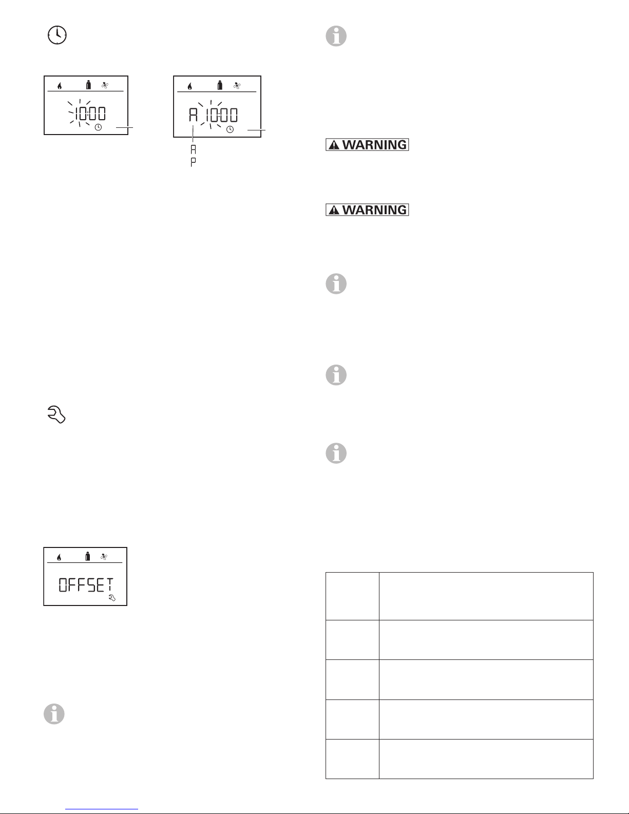
Set clock
4
= p. m.
4
Display 24h mode Display 12h mode
With 100% calcification, the warning
“CLEAN” is displayed in the Hot water mode menu (see “Change hot water
mode” page 7) and the AquaGo must
be decalcified.
2.2 CLEAN
(Only AquaGo comfort / AquaGo comfort plus.)
= a. m.
Fig. 15
Fig. 16
Use the rotary push button(Fig.1–8) to select
the “Set clock” icon in the menu line(Fig.1-4).
The hour display flashes.
1. Use the rotary push button(Fig.1–8) to set
the hours.
2. Tap the rotary push button again and the
minute display flashes.
3. Use the rotary push button to set the
minutes.
4. Tap the rotary push button to confirm the
value.
Service menu
Irritation of skin and eyes in
case of contact with decalcification agent
Wear protective gloves, eye protection and face
protection to avoid contact.
The directions in the AquaGo
operating instructions must be followed.
Starts or stops the decalcification process.
The AquaGo operating instructions contain
a complete description of the decalcification process (see “Decalcification”).
Start = starting decalcification
Stop = interrupting decalcification
When the decalcification process is interrupted, the AquaGo is automatically rinsed
and can be used only after this.
2.3 HARDN
1. Calibrating the room temperature sensor
of the heater (OFFSET)
The room temperature sensor of the connected
heater can be adjusted individually to suit the
location of the sensor. Settings can be made in
the range from 41°F to 23°F (5 °C to -5 °C) in
1°F (0.5 °C) increments.
Example:
Set room temperature 75 °F;
OFFSET = -1 °F;
Setpoint for heater = 74 °F
Fig. 17
Default setting: 0°F (0°C).
2. AquaGo
Available only when AquaGo is connected.
2.1 CALCI
The appliance must be decalcified
regularly depending on water hardness
and hot water consumption.
Specify the hardness of the water that is used.
Is needed to display the relative calcification of
the AquaGo (see “2.1 CALCI”).
Default = 1
Level Water hardness
(mg/l CaCO)
1 Soft
0 - 60
2 Moderately hard
61 - 120
3 Hard
121 - 180
Indicates the relative level of calcification of the
AquaGo as a percentage.
4 Very hard
> 180
9
Page 10
3. °C / °F temperature display
Select temperature display °C (Celsius) or
°F(Fahrenheit).
Fig. 18
Example:
H 1.20.01 –> H = appliance;
1.20.01 = Version number
Appliance
P = CPplusVarioHeat
control panel
H = VarioHeat
W = AquaGo
Fig. 22
Default setting: °C (Celsius).
4. Change backlighting
Change the backlighting of the
CPplusVarioHeat control panel in
10increments.
hot
Fig. 19
5. 12h / 24h Mode
Display in 12h (a. m., p. m.) / 24h mode.
8. RESET
The reset function resets the CPplusVarioHeat
control panel to the factory settings. All your
settings are deleted. Newly connected devices
are recognized and recorded in the control
panel.
• Switch on the power supply
– 12 V DC for the CPplusVarioHeat control
panel and VarioHeat heater
Reset
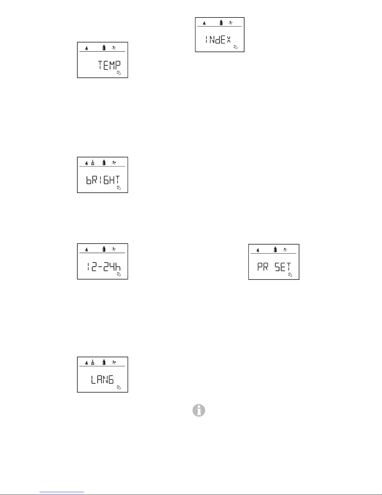
1. Select “RESET” with the rotary push
button(Fig.1–8).
2. Tap the rotary push button.
3. “PR SET” is shown in the display.
4. Tap the rotary push button to confirm.
Fig. 20
Default setting: 24h mode
6. Change language
Select the desired language (German, English,
French, Italian).
hot
Fig. 21
Default setting: English
7. Show the version number
Display the version number of the heater, TrumaAquaGo, CPplusVarioHeat control panel.
Fig. 23
When you have confirmed the selection, the
CPplusVarioHeat control panel is initialized.
“INIT ..” appears on the display while this is in
progress.
Special displays
External control panel (CI-BUS)
If a command is sent from an external control
panel with CI-BUS, “CI” is displayed.
The CPplusVarioHeat control panel CIBUS is a separate variant that is fitted only
in the factory.
10
Page 11
Display energy type
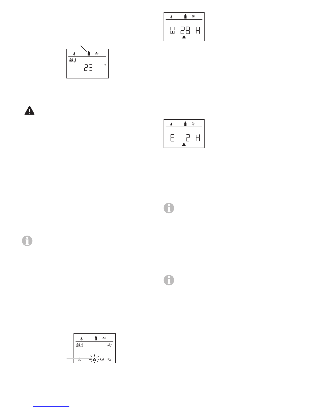
a
a
In heating mode, gas (a) is shown as the energy
type
Fig. 24
Warning / Error
Warning
If an operating parameter is outside the target
range, the Truma CP plus VarioHeat control
panel immediately jumps to the “Warning /
Error” menu level and displays the respective
fault code. The cause of the warning can be
determined and remedied with the aid of the
troubleshooting guide (from page 13 and ff).
Return to setting level
• Tap the rotary push button or press the back
button. If the display is in stand-by mode,
tap to activate the background lighting and
tap again to acknowledge the warning.
If possible, the appliance concerned continues to operate. When the operating parameter is within the target range again, this
icon extinguishes again automatically.
Display warning code
1. Select the icon (“Fig. 25”) with the rotary
push button.
2. Tap the rotary push button.
– The code of the current warning is dis-
played. The troubleshooting chart (refer to
“Troubleshooting” on page13 and ff)
can be used to determine the cause of the
warning and remedy the error.
W = Warning
28 = Error code
H = Appliance
H = VarioHeat
W = AquaGo
Fig. 26
Malfunction
In the event of an error, the Truma CP plus VarioHeat control panel immediately jumps to the
“Warning / Error” menu level and displays the
respective fault code. The cause of the error can
be determined and remedied with the aid of the
troubleshooting guide (from page 37 and ff).
E = Error
2 = Error code
H = Appliance
H = VarioHeat
W = AquaGo
Fig. 27
Cause remedied / return to setting level
• Tap the rotary push button.
– The respective appliance is restarted.
This may take a few minutes due to internal
time lags of connected appliances.
If the cause was not remedied, the malfunction will occur again and the control
panel will again go to the “Warning / Error”
menu level.
Cause not remedied / return to setting level
• Press the back button.
In this case, the error is not acknowledged
in the CPplusVarioHeat control panel and
the warning icon (“Fig. 25”) remains . The
appliance remains in error status. Other
connected appliances can be operated.
Reading out the error fault code
When the error has been acknowledged, the
fault code can be opened again:
Fig. 25
1. Select the warning symbol (“Fig. 25”) with
the rotary push button.
2. Tap the rotary push button. The current error
fault code is displayed.
11
Page 12

Maintenance
This control panel is maintenance-free.
To clean the front, you can use a non-abrasive
cloth moistened with water (and a neutral soap
solution).
Technical data
Display
LCD, monochrome, with backlighting
Diagonal 3.3in. (84mm)
Dimensions (L x W x H)
3.62 x 4.06 x 1.58in. (92 x 103 x 40mm)
Operating temperature range
13°F to 140°F (-25°C to +60°C)
Storage temperature range
13°F to 158°F (-25°C to +70°C)
Interface
TIN bus
Power supply
8 – 16.5VDC
Power consumption
max. 65mA (100% backlighting)
10mA (stand-by)
Quiescent current
3 mA (Off)
Weight
approx. 0.22lb (approx. 100 g)
Protection class
Class III
Protection type
IP00
Subject to change without notice.
12
Page 13
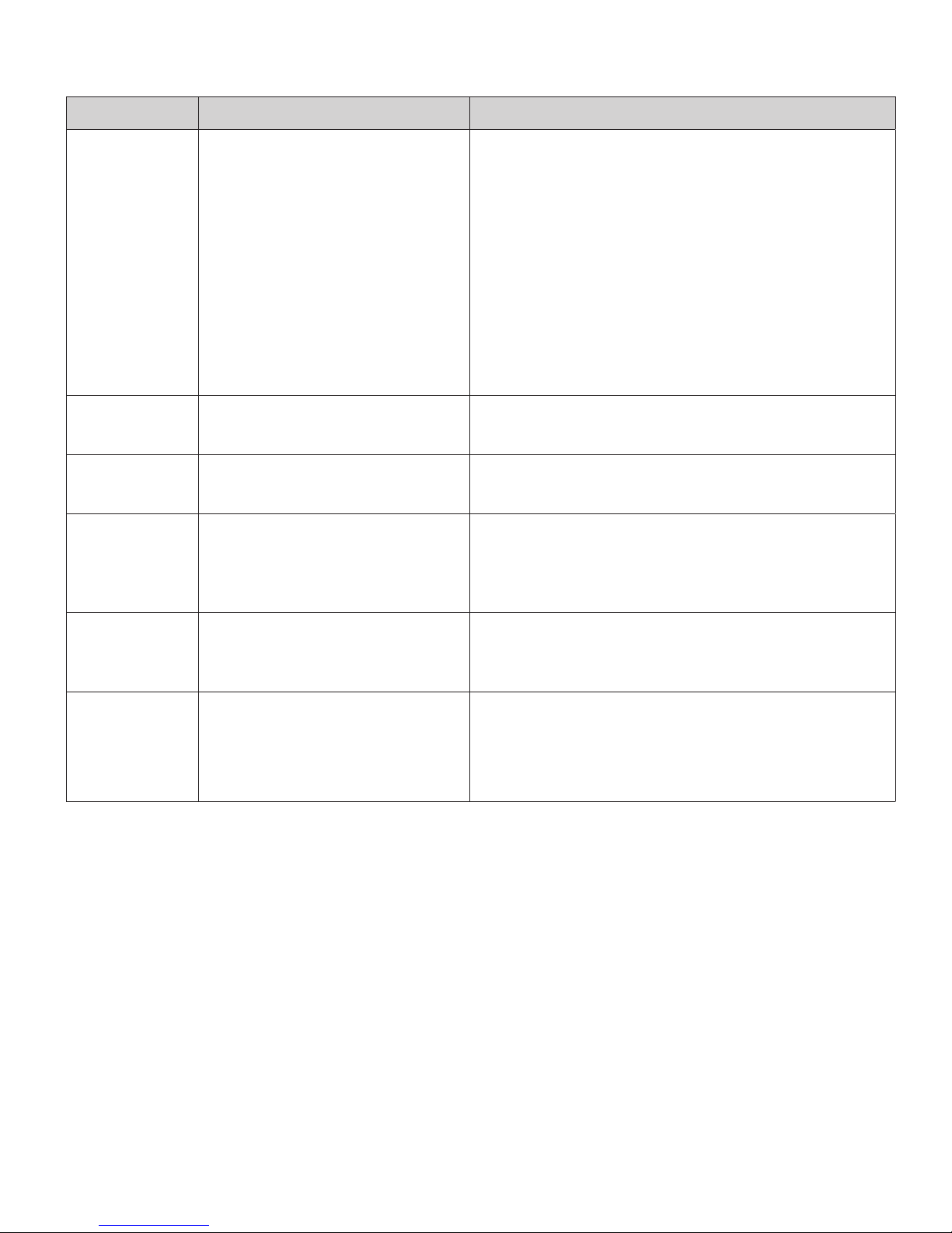
Troubleshooting chart VarioHeat (H)
Error code Potential cause Solution
E 2 H
E 16 H
W 25 H
W 26 H
W 27 H
Flame not detected:
• Gas cylinder empty
• Gas cylinder or quick-act-
• Replace gas cylinder
• Check the gas infeed and open the valves
ing valve in the gas supply
line closed
• Butane concentration in
the gas cylinder too high
• Combustion air infeed or
exhaust gas outlet closed
• Use propane (butane is not suitable for heating, especially at temperatures below 10 °C)
• Check openings for dirt (slush, ice or leaves)
and remove
• Excess voltage >16.4VDC • Check battery voltage and power sources,
such as battery charger
• Undervoltage, battery volt-
• Charge the battery, replace old battery
age too low < 10VDC
• Warm air outlets blocked
• Circulated air intake
blocked
• Remove blockage
• Remove blockage
• Open EN end outlet
• EN end outlet closed
W 29 H
• Imminent undervoltage,
• Charge battery
battery voltage too low <
10.4VDC
W 255 H • Heater has no 12VDC
• Ensure 12VDC power supply
power supply
• No connection between
• Connect heater and control panel
heater and control panel
If these measures do not remedy the malfunction or if error codes are displayed that you
cannot find in the troubleshooting chart, contact your dealership, Truma Service 1-855558-7862 or one of our authorized Service Partners.
13
Page 14
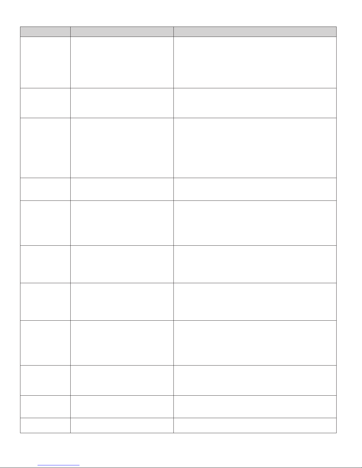
Troubleshooting chart AquaGo (W)
Error code Potential cause Solution
E 1 W Flame not detected There is a flame-detection error at the burner be-
cause the flame was not detected after release of
gas and ignition.
Important: The system indicates this error only
after three attempts at intervals of approximately
30 seconds.
E 2 W Error at over temperature
switches (EOS, BOS)
E 3 W Error at exhaust pressure
switch (EPS)
E 4 W Error at water over tempera-
ture switch (WOS)
E 5 W Flame detected at incorrect
time
E 6 W Error in the safety circuit for
gas valve
The exhaust over temperature switch (EOS) or
burner over temperature switch (BOS) is open/
unplugged.
The EPS did not close when the flue fan was actuated because the fan did not push enough air
through the exhaust channel. A cause could be,
e.g., blocking of the exhaust channel or a faulty
switch.
OR The EPS is closed even though the flue fan is
not running. Cause is a defective EPS or flue fan.
The WOS opened at a water temperature of over
185°F (85°C).
There is an error in flame detection of the burner
because the flame was detected:
• before ignition or
• before the release of gas or
• after the gas was switched off.
There is a heating request but gas cannot be
released.
One of the switches WOS, EOS, BOS, EPS is
open/unplugged.
E 7 W Error of burner MCU internal
RAM
E 9 W Malfunction of water outlet
temperature sensor WOT
E 10 W Error in the safety circuit There is a heating request but gas is not re-
E 11 W Error of MCU watchdog gas
release
W 12 W Internal error
14
Error detected in the burner MCU’s internal
safety monitoring feature (safety variables are no
longer correct or RAM/STACK was overwritten by
mistake).
Water outlet temperature sensor WOT
• has a short circuit or
• is open/unplugged.
• the temperature of the sensor is colder than
14°F (-10°C).
leased because a valve-actuation signal was not
activated.
There is a heating request but the MCU watchdog does not release the gas path.
Page 15
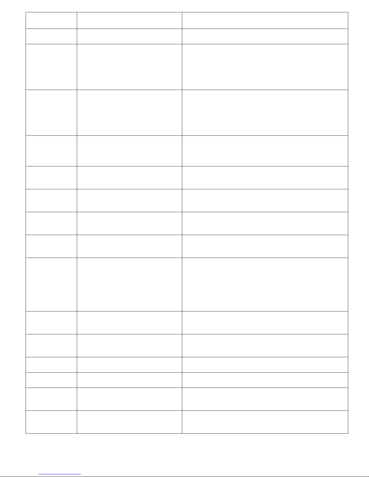
W 13 W Short circuit shut-off valve Short circuit detection in the gas valve (shut-off
part) detected a current >1000 mA and shut off.
W 16 W Malfunction of the MCU Internal error of the control unit.
W 20 W Malfunction of water inlet
temperature sensor WIT
Water inlet temperature sensor WIT
• has a short circuit or
• is open/unplugged or
• the temperature of the sensor is colder than
14°F (-10°C).
W 21 W Malfunction of circulation line
temperature sensor WCT
Circulation line temperature sensor WCT
• has a short circuit or
• is open/unplugged or
• the temperature of the sensor is colder than
14°F (-10°C).
E 22 W Malfunction of gas valve,
modulation section
Error at gas valve, modulation level, because
• the modulator has a short circuit or
• is open/unplugged.
W 23 W Voltage is too high The main power supply’s voltage detector mea-
sured a voltage level of >16.4 V.
W 24 W Voltage is too low The main power supply’s voltage detector mea-
sured a voltage level of <10 V.
E 25 W Flue fan current consumption
error
The current detector for the flue fan has measured a current outside the permitted limits.
W 26 W Circulation pump current con-
sumption error
W 27 W Water circulation pump is run-
ning dry.
The current detector at the circulation pump has
measured a current outside the permitted limits.
• The circulation pump does not generate water
flow. The water system may not be filled or
not sufficiently vented.
• The circulation pump tries (20 times) to generate a water flow every 30 s (if successful, the
error is reset).
W 28 W Too low gas pressure. Gas supply (in vehicle) to the appliance
insufficient.
W 29 W Too high heat power required. You are trying to use more hot water than the ap-
pliance can supply.
W 30 W Risk of freezing. Temperature in the appliance below 27 °F (3 °C).
–
W 31 W Decalcification finished.
W 32 W Current too low. Current in the antifreeze kit too low (e.g. cable
break).
W 33 W Current too high. Current in the antifreeze kit too high (e.g. short
If these measures do not remedy the malfunction or if error codes are displayed that you
cannot find in the troubleshooting chart, contact your dealership, Truma Service 1-855558-7862 or one of our authorized Service Partners.
circuit).
15
Page 16
Installation instructions
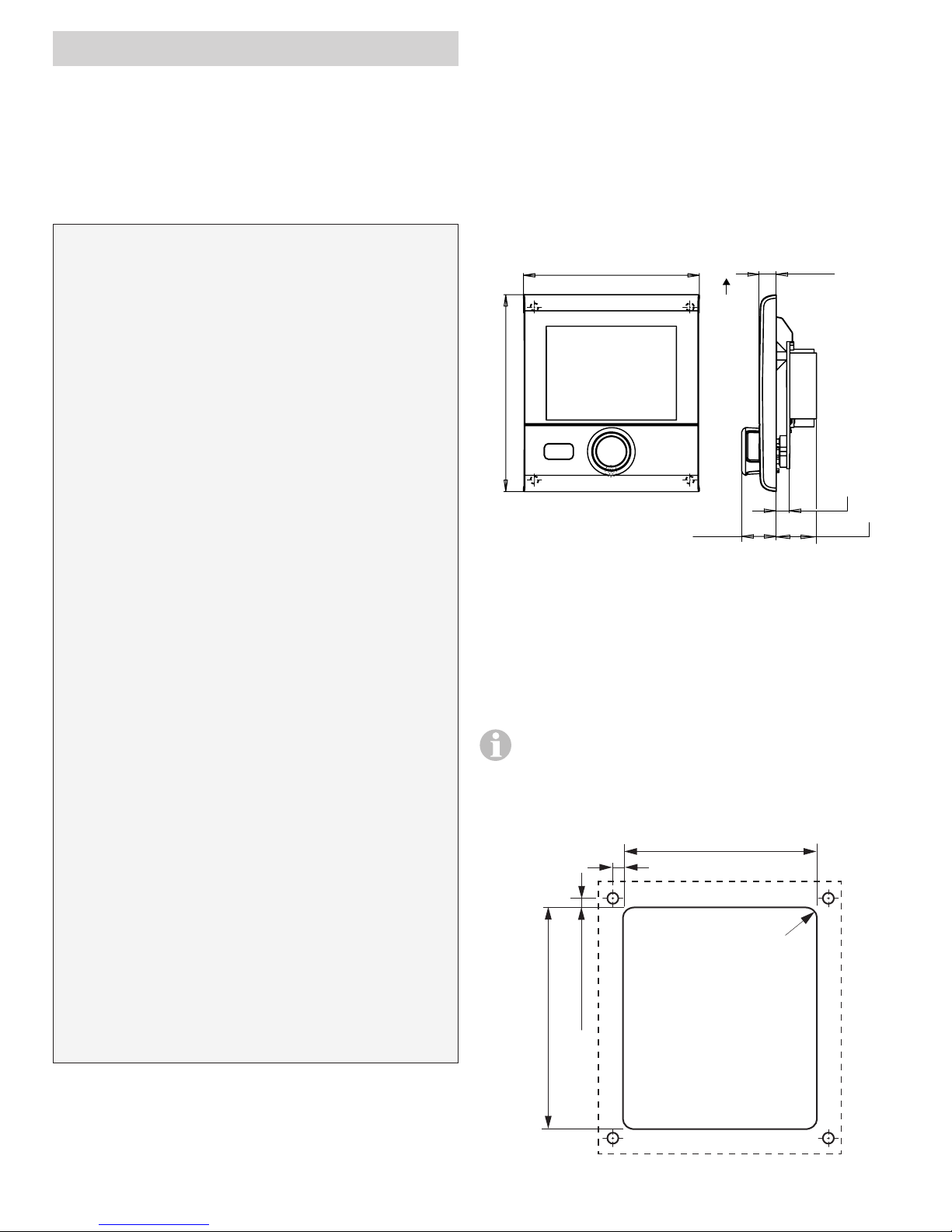
3.62 in. (92 mm)
4.06 in. (103 mm)
0.35 in.
0.87 in. (22 mm)
Read and follow safety rules and instructions before operating this control panel
Truma CPplusVarioHeat.
Safety Information
• Installation and Service must be performed
by an authorized Truma recommended
installer, service agency or OEM. Improper
installation, alteration, service or maintenance can cause property damage, personal injury or loss of life.
• Do not attempt installation as a Do-it-Yourself project.
• Install in recreational vehicles (RVs) only.
RVs are recreational vehicles designed as
temporary living quarters for recreation,
camping, or travel use; such vehicles have
their own power or are towed by another
vehicle.
Description
The CPplusVarioHeat control panel (with polarity protection) is supplied with voltage via a
12V connector cable. The control panel is connected with a VarioHeat and/or AquaGo with a
connector cable (TIN bus).
Dimensions
(9 mm)
To p
0.28 in. (7 mm)
0.71 in. (18 mm)
• DO NOT modify the appliance in any
way. This is dangerous and will void the
warranty.
• DO NOT HI-POT appliance unless electronic (circuit board) has been disconnected.
• DO NOT use battery charger to supply
power to appliance, even when testing.
• DO NOT connect the 12 Volt DC power to
the appliance if the vehicle requires welding. Electrical welding will cause serious
damage to the appliance.
• DO NOT shorten the electrical connection
cable(s) or remove the sticker that indicates
polarity.
• Switch off the vehicle’s on-board power
supply during installation and when connecting the appliance.
• The appliance may be installed only in the
specified position.
USA and CANADA
This appliance must be installed in accordance
with local codes or, in the absence of local
codes, the Standard for Recreational Vehicles,
ANSI A119.2/NFPA 501C or CAN/CSA-Z240 RV.
16
Fig. 28 – Image not to scale
Installation location
Install the control panel in a location that is protected from moisture and wetness.
Install the control panel at eye level so that
it is easy to read the display.
• Prepare an installation opening for the control panel.
+0,04 in.
2.87
0.14 in. (3.5 mm)
±0,04
mm)
+1
in. (84
0.14 in. (3.5 mm)
+0,04
3.31
Fig. 29 – Image not to scale
0.12
(73
in. (3
+1
mm)
+1
mm)
Page 17
Wiring diagram
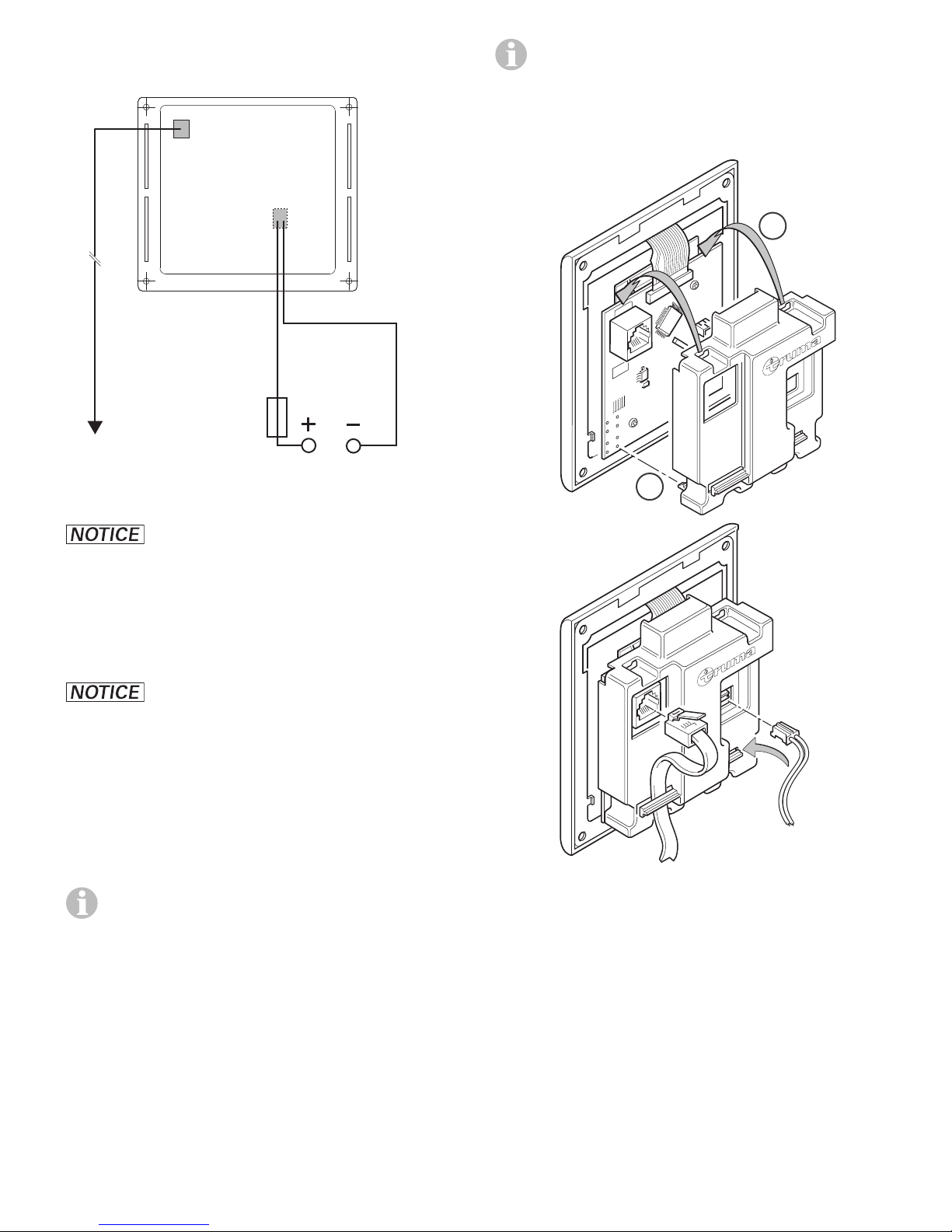
12 VDC
TIN-Bus
RJ-12 female
2 x RJ-12 male
connecting cable
VarioHeat
AquaGo
Fig. 30 – Rear view
+
1 A
In installation situations where the back of
the CPplusVarioHeat is freely accessible,
the CP plus cover (contact safety device),
which is available as an accessory, may be
used.
-
1
red
red / black
2
If any of the original wire as supplied
with the appliance must be replaced, it must be
replaced with wire AWG# 18 - 105 °C - UL1015
or its equivalent.
Connection
Danger from electrostatic
charge. Electrostatic charges can destroy the
electronics.
• Establish a connection to ground (po-
tential equalization) before touching any
electronics.
• Observe the ESD regulations.
Install the connector cable (TIN bus) in a
loop so that it is not under tension. It must
be possible to pull the control panel about
8in. (20cm) out of the installation opening
–
with no tension on the connector. Do not
pull on the connector cable (TIN bus) when
it is plugged into the control panel.
Fig. 31 – CP plus cover (contact safety device)
• Plug the connector cable (TIN bus) into
the control panel and run the cable to the
VarioHeat and / or AquaGo.
• The plus cable must be protected with a
1 ampere fuse.
• Plug in the 12V connector cable and connect to a 12VDC power supply (permanent
plus).
17
Page 18
Installation
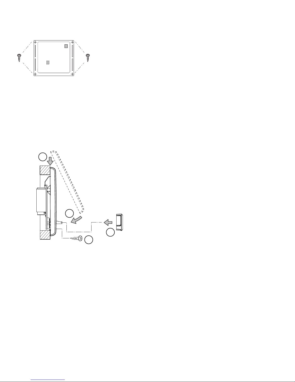
• Mount the control panel frame on to the wall
with 4screws.
Ø Maximum
-
+
Fig. 32 – Front view
• Hook the top of the control panel into the
frame via 2latches.
• Fix the top of the control panel in place with
a screw (supplied).
• Slide the rotary push button on to the shaft.
0.134 in. (3.5 mm)
1
2
4
3
Fig. 33 – Assemble top of control panel and rotary push button
Subject to change without notice.
18
Page 19

Page 20

In case you encounter any problems,
please contact the Truma Service
Center at 855-558-7862 or one of our
authorized service partners. For details see
www.truma.net.
Please have the model number and serial
number (on furnace’s type plate) handy
when you call.
Manufacturing
Truma Gerätetechnik
GmbH & Co. KG
Wernher-von-Braun-Straße 12
D - 85640 Putzbrunn
Germany
www.truma.com
Sales
Truma Corp
825 East Jackson Blvd.
Elkhart, IN 46516
USA
Toll Free 1-855-558-7862
Fax 1-574-538-2426
[email protected]
www.truma.net
39050-00552 · 00 · 09/2018 · ©
 Loading...