

Page 1
LS & LSS Series
TRUFLO LSS & LS SERIES INSTALATION MANUAL
PADDLE WHEEL FLOW METER
½" - 24"
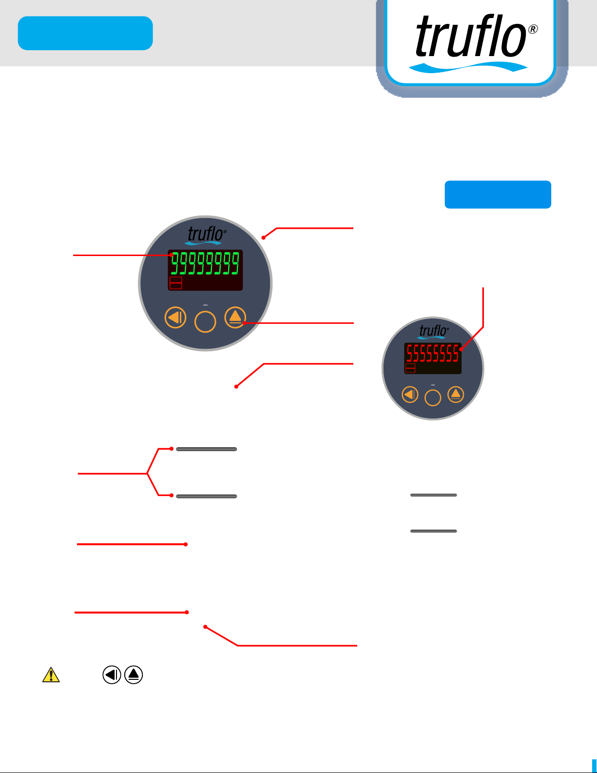
4-20mA
Large Green
LED Display
Double
O-Ring Seal
OUT1
OUT2
RST
P/O
DIO
RATE
TOTAL
D S
ENT
FUNC
GAL
TON
Liter/min
3
M
/Hour
ALARM
+2 Relays
Push Buttons
All Plastic Design
Changes to RED LED
(Alarm Status) Relays Active
OUT1
P/O
RATE
GAL
Liter/min
3
M
TOTAL
D S
ENT
FUNC
TON
/Hour
ALARM
OUT2
RST
DIO
PP/PVDF Body
Ceramic Shaft
Bearings
PFA (Teflon®) Paddle
Press at the Same Time during Programming to Return to Home Screen
Read the user's manual carefully before starting to use the unit or Programming.
Manufacturer reserves the right to implement changes without prior notice.
Find Quality Products Online at: [email protected]
www.GlobalTestSupply.com
Page 2
LS & LSS Series
Quick Start
LS & LSS Series Proper Installation Instructions
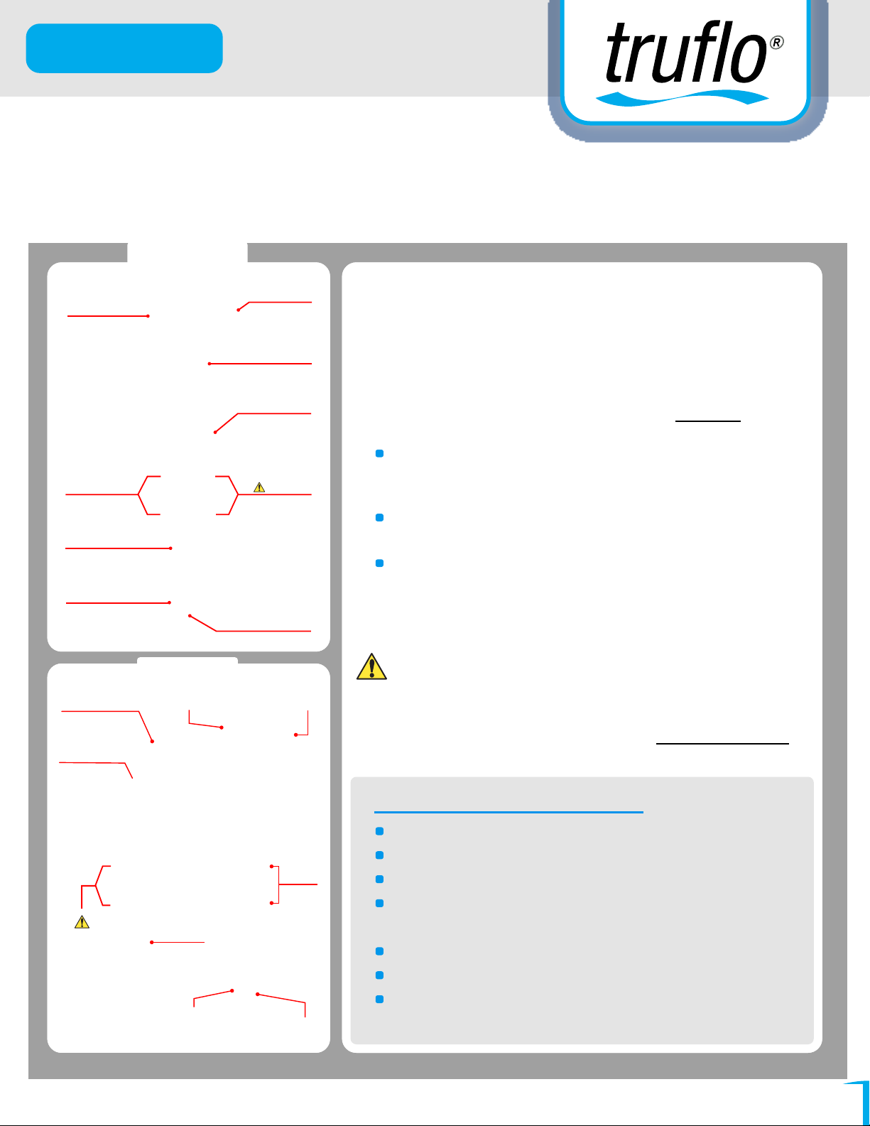
LSS Series
LED Display
Double
O-Ring Seal
PP,PVDF Body
Ceramic Shaft
Bearings
Frequency + (NPN)
Pulse Output
Epoxy Sealed
(Water Tight)
PFA (TeFlon) Paddle
LS Series
Quick
Disconneet
4-20mA
+2 Relays
Push Buttons
All Plastic Design
Lubricate
O-Rings
Before Installing
Frequency + (NPN)
Pulse Output
Operating Instructions
for Truflo LS & LSS Series and Flow Meter
LS & LSS Series Paddlewheel Flow Sensors are Very
Accurate, Heavy Duty Sensors that offer Exceptional Value.
Truflo Sensors Measure liquid Flow Rates in Full Pipes.
The wetted materials are PFA, Ceramic and PP, PVDF
making this model highly versatile and chemically
compatible with many liquid process solutions.
Sensors can be installed (½ to 24 in.) pipes using
Truflo extensive line of custom fittings.
These fittings, include Tees, Saddles, and
Weldolets, and Align and Position the sensor to the
Proper Insertion depth Providing Accurate Flow
Measurement.
Remember to Lubricate O-Rings (Grease
Supplied) Use an Alternating Twisting Motion
when Carefully inserting Sensor into Fitting (Grease
Included).
Remember this is an Instrument + Handle With Care
Advantages LS & LSS Models :
Flow Rate Range 0.3 to 10 m/s (1 to 33.3 ft/s)
Installs into pipe sizes (½ to 24 in.)
FPM
O-Rings
Wide Turndown Ratio of 33:1
Industry's Most Accurate (0.15%)
Lubricate
O-Rings
Before
Installing
PP, PVDF
Body
Ceramic
Shaft + Bearings
PFA Paddle
Paddle Wheel Flow Meter
Rugged Industrial Design
Easy to Replace Rotor
Industry's Most Chemical Resistant Materials
PP-PVDF-
PFA-Ceramic
DC Power Only
Find Quality Products Online at: [email protected]
www.GlobalTestSupply.com
01
Page 3
LS & LSS Series
Important Proper Installation Method
Ensure Silicon Grease (Supplied)
is Applied Prior to Insertion
Correct Sensor Positioning
(90° Sweet Elbow)
Ensure Location Tabs
Are Parallel to
Direction of Flow
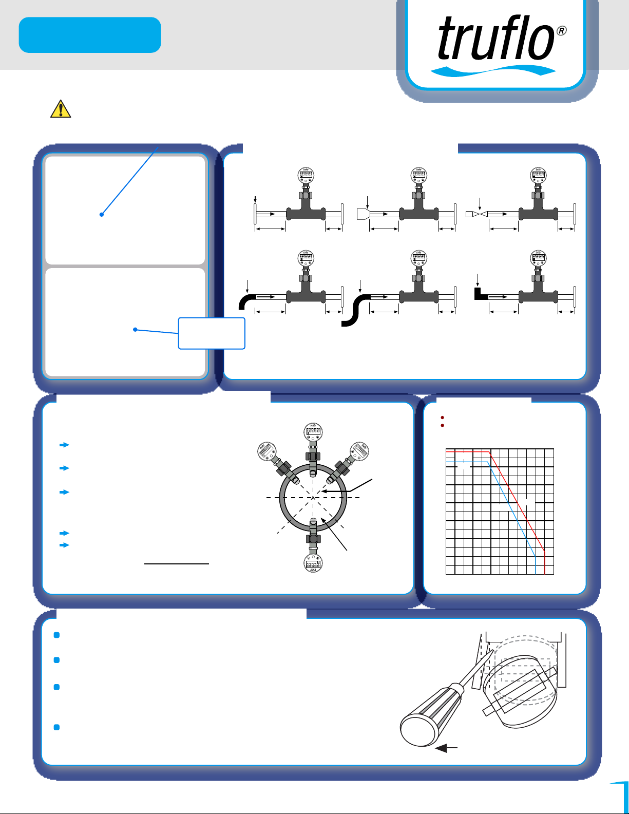
Sensor Mounting Position
Horizontal Pipe Runs :
Mount sensor in the upright (0°) position
for best performance.
Mount at a Maximum of 45° when Air
Bubbles are present.
Do not
mount on the bottom of
the pip
e when Sediments is present.
Vertical Pipe Runs :
Mount sensor in any orientation.
Upward Vertical flow is Strongly
Recommended to Ensur
e Full Pipe.
(Socket Flange)
10xID 5xID
20xID 5xID
Liter/min
P/O RATE GAL
OUT1
OUT2
D/O
TOTALTON M3/Hour
RST
ALARM
D-S
ENT
FUNC
(Reducer)
15xID
Liter/min
P/O RATE GAL
OUT1
OUT2
D/O
TOTALTON M3/Hour
RST
ALARM
D-S
ENT
FUNC
(2x90° Elbow)
25xID
Liter/min
P/O RATE GAL
OUT1
OUT2
D/O
TOTALTON M3/Hour
RST
ALARM
D-S
ENT
FUNC
Liter/min
P/O RATE GAL
OUT1
OUT2
D/O
TOTALTON M3/Hour
RST
ALARM
D-S
ENT
FUNC
Throttled
(Diaphragm/Gate)
5xID
(2x 90°Elbow 3 dimensions)
5xID
50xID
10xID
Always Maximize the Distance Between
Flow Meter and the Pump / Valve or Fitting.
Maximum Operating
Pressure/Temperature
PP Body : (180psi @ 68°F) (25psi @ 176°F)
PVDF Body : 200psi @ (-20 to
Temperature (°F)
-4
14 31 54 68 86 104 122 140 158 176194 212
14
13
12
36psi @ 80°C (188°F)
PVDF
PP
11
10
9
8
7
6
Pressure (Bar)
5
4
3
2
1
0
-24 -10 0 10 20 30 40 50 60 70 80 90 100
Temperature (°C)
PP
27°C) (-4 to 81 F)
PVDF
- 45°
0°
Liter/min
P/O RATE GAL
OUT1
OUT2
D/O
TOTAL TON M3/Hour
RST
ALARM
D-S
ENT
/Hour
3
Liter/min
M
GAL
ALARM
TON
E
RAT
TOTAL
P/O
D/O
D-S
1
T
U
O
2
T
U
O
ENT
RST
FUNC
FUNC
+ 45°
OUT1
OUT2
P/O
RST
D/O
RATE
TOTAL
GAL
TON
D-S
Liter/min
M
ENT
3
ALARM
/Hour
FUNC
IF AIR
Bubbles
Present
RST
OUT2
OUT1
Ensure
No Sediment
FUNC
ENT
D-S
ALARM
D/O
TOTAL TON M3/Hour
P/O RATE GAL
Liter/min
180°
Liter/min
P/O RATE GAL
OUT1
OUT2
D/O
TOTALTON M3/Hour
RST
ALARM
D-S
ENT
FUNC
5xID
Liter/min
P/O RATE GAL
OUT1
OUT2
D/O
TOTALTON M3/Hour
RST
ALARM
D-S
ENT
FUNC
5xID
203.0
188.5
174.0
159.5
145.0
130.5
116.0
101.5
Pressure (psi)
87.0
72.5
58.0
43.5
29.0
14.5
0
Rotor Replacement Procedure
To remove the rotor, insert a small screwdriver between the
rotor and the ear of the sensor.
Carefully Twist the screwdriver blade to flex the ear outward
enough to remove one end of the rotor and pin.
DO NOT flex the ear any more than necessary! If it breaks, the
sensor cannot be repaired and will not be considered as a valid
warranty claim.
Install the new rotor by inserting one tip of the pin into the
hole, then Carefully flex the opposite ear back enough to slip
rotor into place.
Small Screw Driver
(Supplied)
DC Power Only
Find Quality Products Online at: [email protected]
www.GlobalTestSupply.com
02
Page 4
LS & LSS Series
Important Proper Installation Method
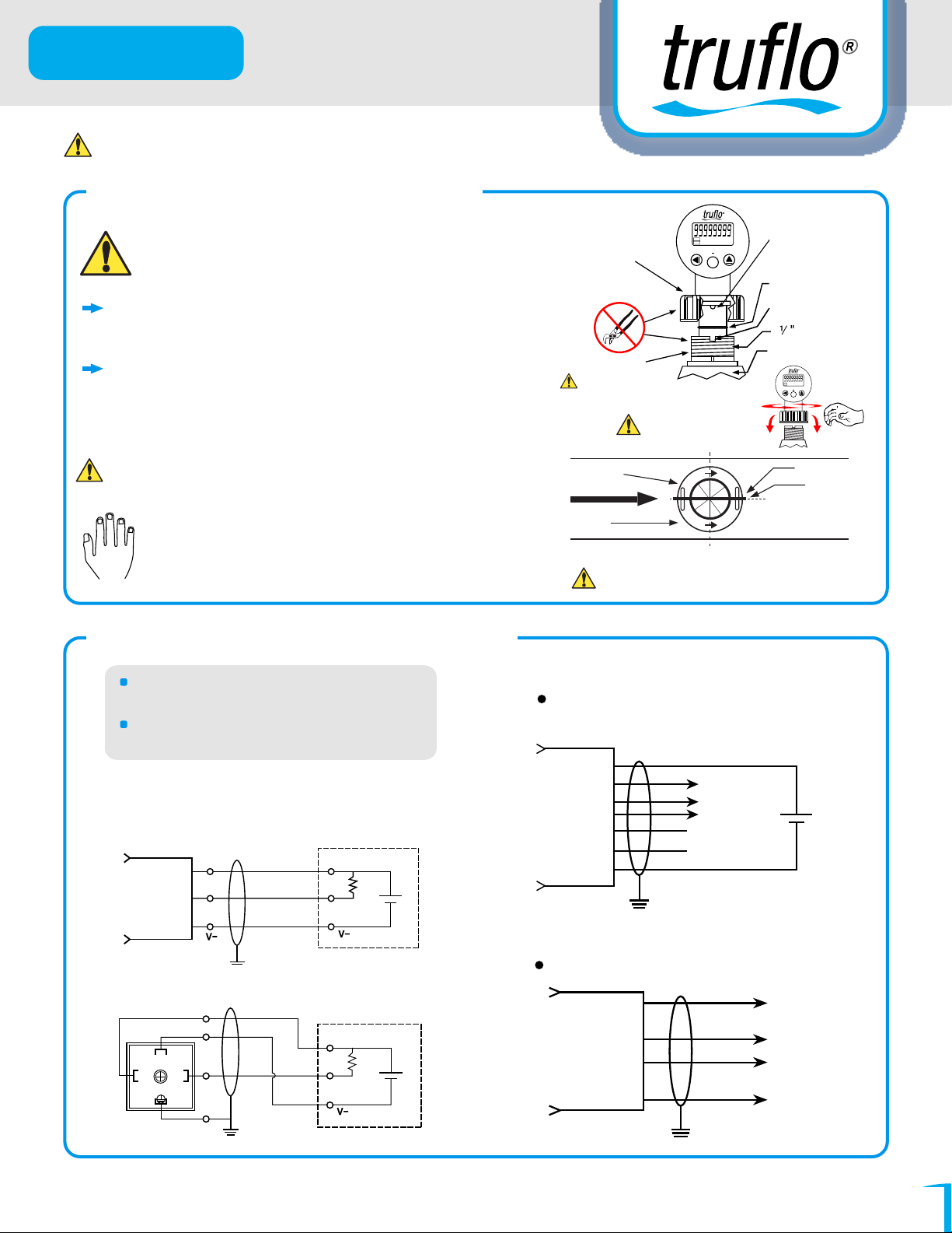
LS & LSS Sensor Installation
Lubricate O-rings with a Viscous Lubricant
(grease) compatible with the system. Very
Important (Grease Enclosed)
Using an Alternating/Twisting Motion, Carefully
lower the sensor into the fitting. Do Not Force
Engage one thread of the sensor cap then turn the
sensor until the alignment tab is seated in the
fitting notch (Fig-1) Ensure Tab is Parallel to Flow
Direction.
Ensure Tab / Notch are Parallel to Flow Direction
Fig-2
Hand Tighten the Sensor Cap. DO NOT use
any tools on the sensor cap or the cap threads
or fitting threads may be damaged, see Fig-1
Sensor Wiring (DC Power Only)
Black
Screw Down
Retention Cap
OUT1
P/O
RATE
GAL
Liter/min
3
M
OUT2
TOTAL
TON
DIO
RST
ALARM
D S
ENT
FUNC
/Hour
Flow Meter
Positioning
Tab
Ensure O-Rings
are well Greased
Notch
1 NPT
Fitting (Custom)
Lubricate (Grease)
Inside of Insertion
Fitting
Black Retention cap
Direction
of flow
Fig-1
Alternating/Twisting
Motion,
To Flow Direction
Fig-2
Ensure Tab is in Line with Flow Direction
4
OUT1
P/O
RATE
GAL
Liter/min
3
M
/Hour
OUT2
TOTAL
TON
DIO
RST
ALARM
D S
ENT
FUNC
Sensor Blade
Ensure Tab
is Parallel
PROCESS PIPE
(TOP VIEW)
Use conductor shielded cable 24V DC
(20-26 ANG).
Cable shield must be maintained
through cable splice.
LS Sensor Wiring Diagram 5-24VDC
3 Cond.+ Shield,
28AWG.PVC(105°C)
Brown
Black
Blue
Black = Pulse
V+
O/P
COM
Drain Wire
DIN Quick Connector
V+
COM
3
1 2
O/P
GND
Ground
Fly Leads
(LS-XXE)
V+
I/P
COM
(LS-XXD)
V+
I/P
COM
LSS Series
14-28VDC
Analog (4-20mA)/RS-485/Pulse
Output Type (Depending on Type)
Brown
Gray
Red
Yellow
Black
White
Blue
A/O(+) (4-20mA)
D+
RS-485
D-
C
(Pulse O/P)
E
A/O(-) (4-20mA)
VDC (+)
VDC (-)
LSS Series
Relay Outputs
Red
(OUT1)
Black
White
(OUT2)
Green
DC Power Only
Find Quality Products Online at: [email protected]
www.GlobalTestSupply.com
03
Page 5
LS & LSS Series
TRUFLO LSS PROGRAMMING
INSTRUCTION MANUAL
PADDLE WHEEL FLOW METER
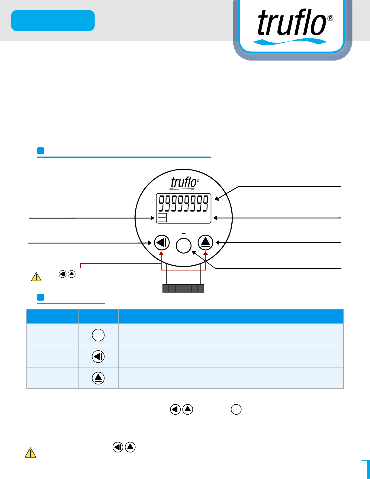
FRONT PANEL & KEY FUNCTIONS
Bright LED Display Changes From
Green to Red in Alarm Mode
Alarm Relay Status
Shift Left Key & Total
Reset Key (Hold 10 Sec)
Press at the Same Time during
Programming to Return to Home Screen
OUT1
OUT2
RST
P/O
DIO
RATE
GAL
TOTAL
TON
D S
ENT
FUNC
Liter/min
3
M
/Hour
ALARM
LSS SERIES
Key Name Symbol Descriptions
Enter Key &
Save Key
Shift Key &
Total Reset Key
UP Key &
Alarm Setting Key
ENT
1. In the Measuring Status, Press this Key for 5 sec to enter Programming.
2. In the Measuring Status, Press this Key to Switch the Rate & Total Value.
3. In the Measuring Status, Press this Key to Save the Value & Go to Next Programming Screen.
1. Press this Key for 10 sec to Reset the Total Value.
2. Pressing this Key will Move the Cursor Left.
1. Press this Key for 5 Sec to Enter to Alarm Programming Screen.
2. Pressing this Key will Increase the Digits.
Engineering Units
Up Key & Alarm Setting
(Hold 5 Sec)
Enter & Switching
Display Key Press
(7 Sec)
1.
To modify the Settings, please press and press to save the Settings after the
ENT
modification is made.
Remember the New Passcode If Changes Are Made!
2.
In any Screen, press , Together During programming Stage to return Immediately to
3.
Home screen (Note : AFTER 2 mins the Display will Return to Home Screen.
Find Quality Products Online at: [email protected]
www.GlobalTestSupply.com
04
Page 6
LS & LSS Series
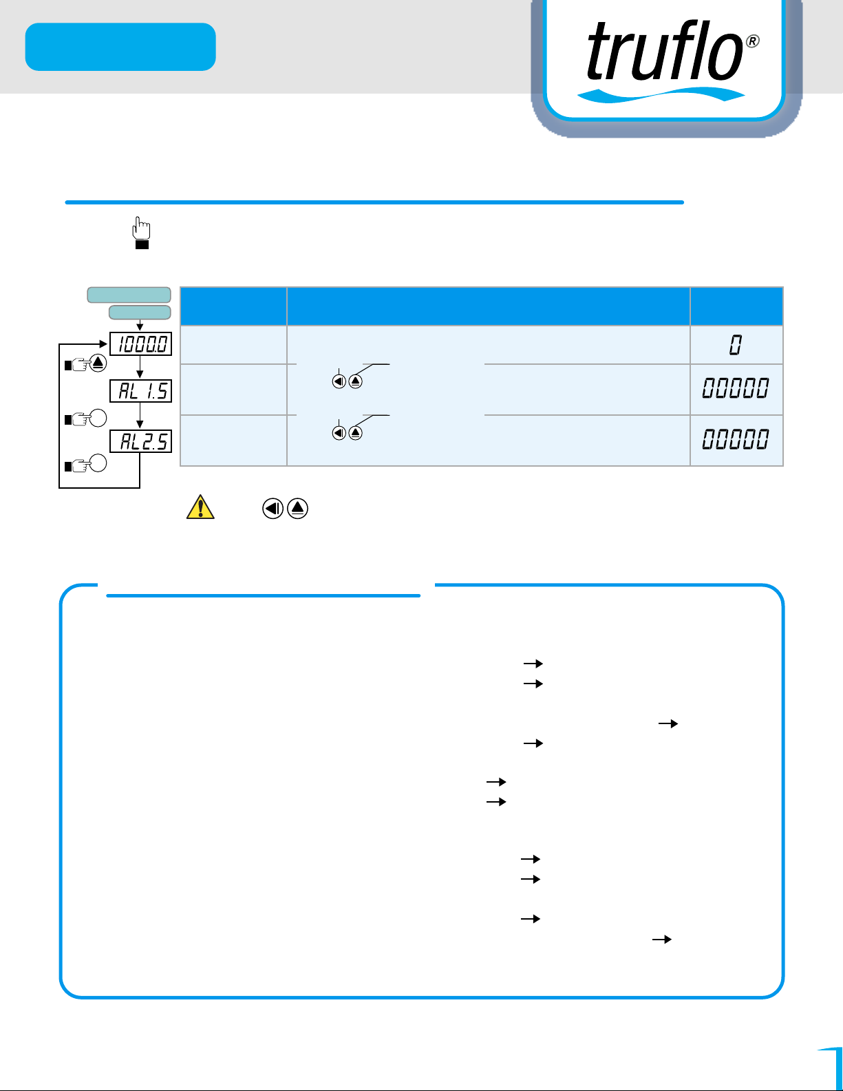
GENERAL MODE OPERATING PROCEDURES
Follow Hand For Programming
Alarm Setpoint
Block Charts
Power On
Display Descriptions
Default
Press
(5 Sec)
Press
(1 Sec)
Press
(1 Sec)
ENT
ENT
Measuring
Status
Alarm 1 Setpoint
(AL1)
Alarm 2 Setpoint
(AL1)
Current Value On Display
To Move Cursor To Increase or Decrease
Press to Modify Alarm 1 Setpoint. (Flow Rate) Display Changes
From Green to Red In Alarm Start
To Move Cursor To Increase or Decrease
Press to Modify Alarm 2 Setpoint. (Flow Rate) Display Changes
From Green to Red. In Alarm State
Press at the Same Time during Programming to Return to Home Screen.
FLOW ALARM MODE
When AL=HI, DELAY= 0 :
Current Value > Programmed Value (AL) + Hysteresis (HYS) (Relay On)
Current Value < Programmed Value (AL) – Hysteresis (HYS) (Relay Off)
When AL=HI, DELAY= 1 – 99 sec.:
Current
Current
When AL=HI, DELAY= -1 – 99 sec.:
Current Value > Programmed Value (AL) + Hysteresis (HYS) (Relay On + (DEL) and then off)
Current Value < Programmed Value (AL) – Hysteresis (HYS) (Relay Returns to Normal State After the
Procedure)
When AL=LO, DELAY= 0 :
Current Value > Programmed Value (AL) + Hysteresis (HYS) (Relay Off)
Current Value < Programmed Value (AL) – Hysteresis (HYS) (Relay On)
When AL=LO, DELA
Current
Current
Value > Programmed Value (AL) + Hysteresis (HYS) + Delay Time (DEL) (Relay On)
Value < Programmed Value (AL) – Hysteresis (HYS) (Relay Off)
Y = 1 – 99 sec.:
Value > Programmed Value (AL) + Hysteresis (HYS) (Relay Off)
Value < Programmed Value (AL) – Hysteresis (HYS) + Delay Time (DEL) (Relay On)
Find Quality Products Online at: [email protected]
www.GlobalTestSupply.com
05
Page 7
LS & LSS Series
Follow Hand For Programming
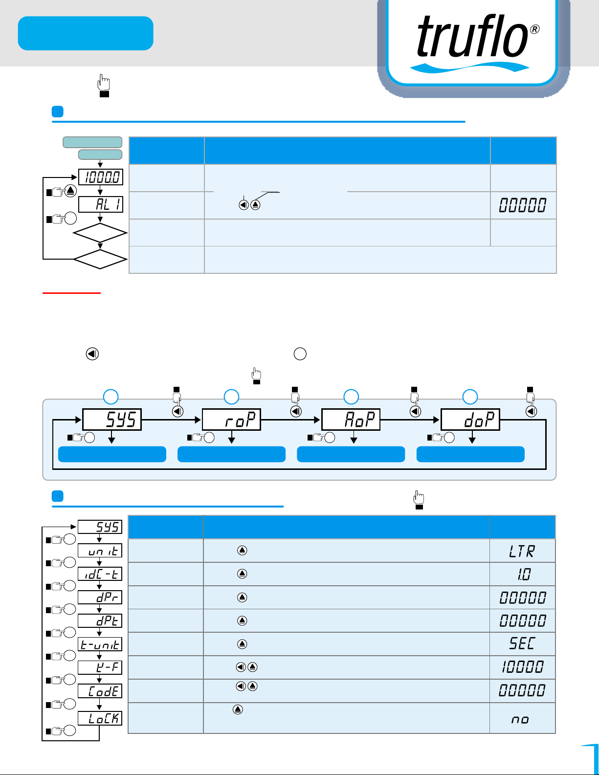
PROGRAMMING MODE OPERATING PROCEDURES
Block Charts
Press
(5 Sec)
Press
ENT
No
Power On
P.Code Correct
Yes
Press ENT
Display Descriptions Default
Measuring
Status
Pass Code (P. Cod)
Current Flow Value. (Press 5 Sec)
To Move Cursor To Increase or Decrease
Press to enter
If
Passcode
is correct
Passcode
.
mode the Flow Meter
will enter into Programming Status.
If Passcode is incorrect the Display will to Return to Measuring Status.
Press Enter Again
Remark :
1.
There are Four (4) Different Programming Windows (1) "System Programming Group (SYS)" (2) "Alarm
Programming Group (roP)" (3) "Analog 4-20mA Output Setting (AoP)" (4) "RS485 (Optional)
Programming (doP)".
2.
Press to select each Section Screen Press to enter Programming page for modifying the
parameters.
1
Press
Follow Hand For Programming
2 3 4
ENT
Press Press Press
Press
ENT
(SYS)
System Programming
Press
ENT
Alarm Programming
System Programming Steps
Press
Press
Press
Press
Press
Press
Press
Press
Press
ENT
ENT
ENT
ENT
ENT
ENT
ENT
ENT
ENT
Display Descriptions Default
Flow Unit Setting
(Unit)
Sampling Time
Base (idC-t)
Decimal Point of
Rate Setting (dPr)
Decimal Point of
Total Setting (dPt)
Time Parameter
Setting (t-unit)
K Factor Setting
(K-F)
Passcode
Setting (CodE)
Key Lock Setting
(LoCK)
Press to modify the Unit of measurement (Liter, Gal, Ton., m3)
Press to Change sampling time (0.5, 1.0, 2.5, 5.0 sec).
Press to select decimal point (0,1,2,3,4) (0 STD).
Press to select total decimal point (0,1,2,3,4) (0 STD).
Press
Press to modify K Factor (0.1~999.999 Section See Fittings Section Page 8)
Press to modify passcode (0~19999).
PS: Please don’t forget the new passcode after Change.
Press to lock the keys, using key lock function allows only viewing of the
programs, but any change any of the values will be blocked.
No (unlock), YES (“ENT” unlock).
(roP)
Press
ENT
(Aop)
A/O 4-20mA Programming
Press
ENT
RS485 Programming
Follow Hand For Programming
to modify time parameter (sec/min/hour) Minutes (Recommeded)
(dop)
Find Quality Products Online at: [email protected]
www.GlobalTestSupply.com
06
Page 8
LS & LSS Series
Press at the Same Time during
Programming to Return to Home Screen
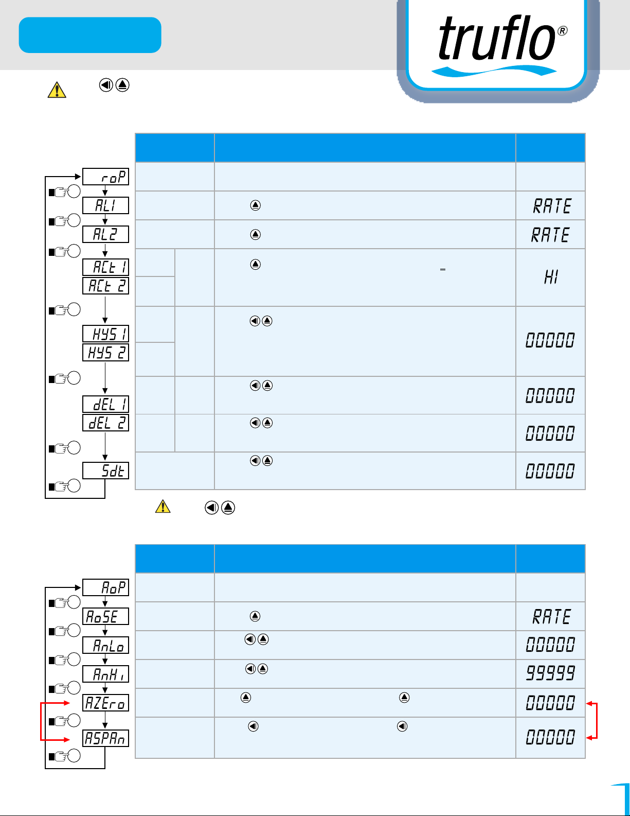
Programming Alarm SET POINTS
Press
(5 Sec)
Press
Press
Press
Press
Press
Press
ENT
ENT
ENT
ENT
ENT
ENT
ENT
Display Descriptions
Alarm Setting
Page (roP)
Alarm 1 Selection
Setting (AL 1)
Alarm 2 Selection
Setting (AL 2)
Alarm 1
(ACt1)
Alarm 2
(ACt2)
Alarm Action
Hysteresis 1
(HYS1)
Hysteresis 2
Alarm
(HYS2)
Delay
Time
1 (dEL1)
Delay
Time 2
(dEL2)
Alarm
Run
Delay
Setting
Alarm
Run
Delay
Setting
Alarm Start Band
Time Setting (Sdt)
The following steps are only available for alarm output.
Press to select alarm 1 (Flow Rate or Total).
Press to select alarm 2 (Flow Rate or Total)
Press to Change Alarm Set Point Value that is > (Hi) or <(Lo)
for alarm Relay action.
Setting
Hi = Above Current Flow
Lo = Below Current Flow
Press to modify the Hysteresis value, when Flow Rate runs below or above
display value (depends on alarm action). Alarm setpoint ± this value (0~999) will turn
off the alarm. Not
Setting
Hysteresis
then the Hysteresis will b
e : If AL1.5 or AL2.5 are set to Alarm based on Total (see above)
e Disabled
Press to modify the value, Based on Value Entered the Alarm will
activate only when the Display Value is Reached and the time is passed
Initial Start - Up - (Prevents False Alarms)
Press to modify the value, when the display value reach the alarm
value Set the delay (sec) before alarm Activates (0~99 sec) for alarm action.
Initial Start - Up - (Prevents False Alarms)
Press to modify the value (0~99 sec), if the display value hits
alarm start band value; the alarm will be active (sec).
Initial Start - Up, Filter Change Out
Default
Press at the Same Time during Programming to Return to Home Screen
Programming 4-20mA Analog Output (A/O)
Display Descriptions
Purposes Only
For Calibration
Press
Press
Press
Press
Press
Press
A/O Programming
(AoP) 4-20mA
ENT
A/O Selection
Setting (Ao. SEL)
ENT
A/O Low Scale
Setting (AnLo)
ENT
A/O High Scale
Setting (AnHi)
ENT
A/O Zero
Adjustment (AZEro)
ENT
A/O Span
Adjustment (ASPAn)
ENT
The following steps are only available for analog output.
Press to select 4-20mA output for Flow Rate or Flow Total.
Press to adjust A/O low scale to correspond to the display value (programmable).
Ex: A/O is 4-20mA the display is 0 to output 4mA, this value must be set for 0
Press to adjust A/O hi scale to correspond to the display value (programmable).
Ex: A/O is 4-20mA, the display is 90.0 to output 20mA, this value must be set for 90.0
Press to select adjusting For Valves Above Flow Rate, press to modify the A/O zero.
PS: Use this function to adjust the real A/O zero. i.e. If you wish to have 0mA read other than 0 i.e. 10 GPM
Press to select adjusting flow rate, press to modify the A/O span.
PS: To use this function to adjust the real A/O span.
i.e. Flow Rate 20mA =150 GPM.
When you wish to Set a pre-determined Max Flow Value
Note : All Sensors are Factory Calibrated - Calibration Not Required
Find Quality Products Online at: [email protected]
www.GlobalTestSupply.com
Default
Purposes Only
07
For Calibration
Page 9
LS & LSS Series
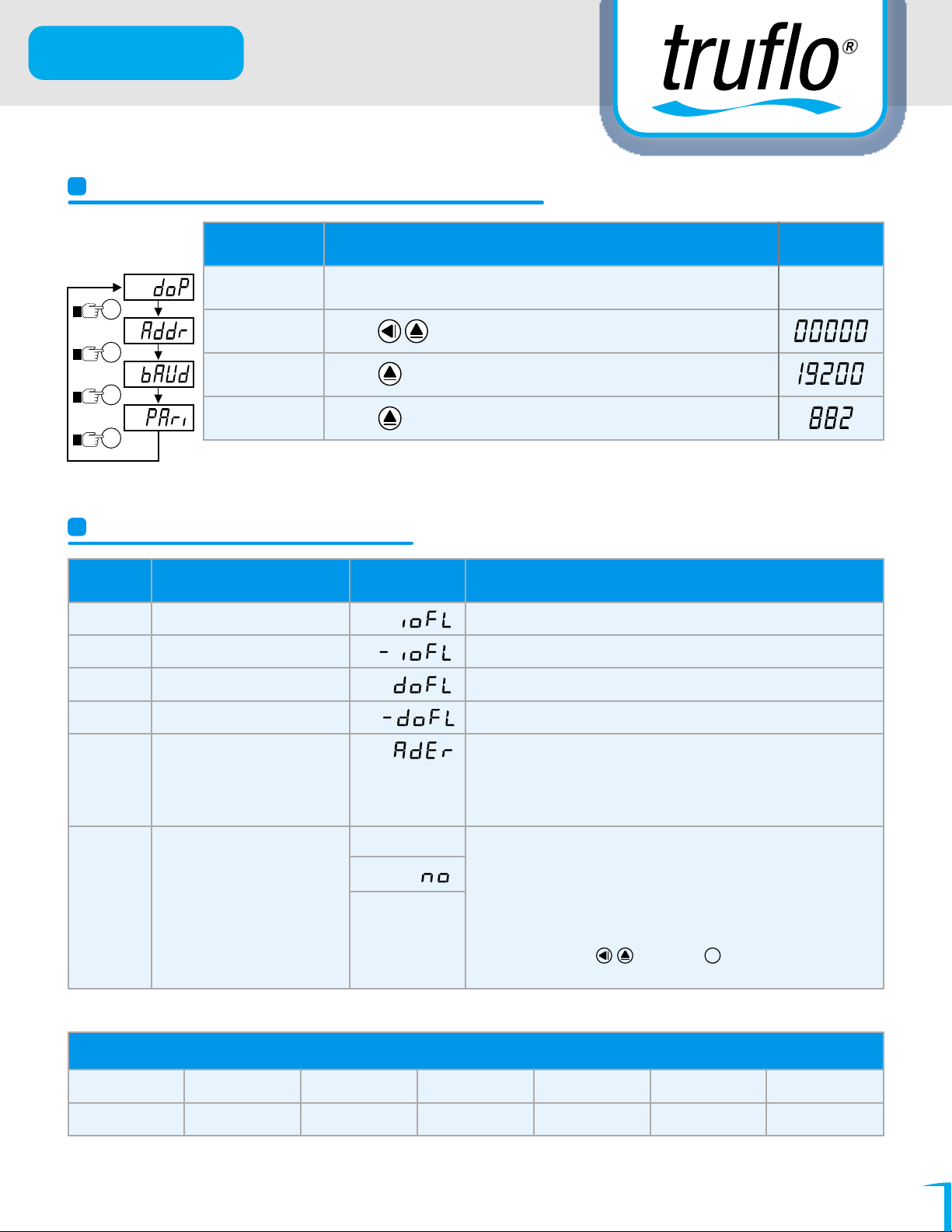
RS485 Setting Procedures (Optional)
Display Descriptions Default
RS485 Setting
Press
ENT
Press
ENT
Press
ENT
RS 485 Only
Press
ENT
Page (doP)
Address Setting
(Addr)
Baud Rate
Setting (bAUd)
Parity Setting
(PAri)
Self-Diagnosis Error Code
Appendix
4
Error Mark Description Error Mark
Input over error detect1
Input under error detect2
Display over error detect 3
Display under error detect
The following steps are only available for RS-485. (Special Order)
Press to modify address (0~255).
Press to select baud rate (19200/9600/4800/2400).
Press to select parity (n.8.2/n.8.1/even/odd).
Analyze & Descri ption
Input signal is over range (120%)
Input signal is under range ( -20% )
Display is over range (99999 ) Over Pressure-Sensor Damage
Display is under range ( -19999)
5
AID Converter error detect 1. Input signal over range (180%)
2. Inside circuit damage
Please movmg input signal if still display ADER ,
please contact us
5
EEPROM error detect
E-00
1. Internal flash memory read/write
2 . Flash memory write about 100 thousand times
(guarantee = 10 years)
Please power reset, if display reads E-OO, Next step:
yes
1 . E-00 & No a1ternate display for inquire reset FLASH memory
2 . Decide Yes with key, press key return normal display
ENT
3. Flash memory was reset, Please follow step 1~12 set again
Pressure Units Conversion Table
Kg / cm2 KPa MPa PSI rnmHg inHgbar
1.01972 100 0.1 14.5036 750.062 29.531
Find Quality Products Online at: [email protected]
www.GlobalTestSupply.com
08
Page 10
LS & LSS Series
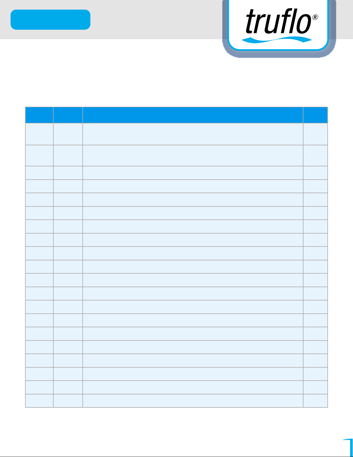
LSS Modbus RTU Mode Protocol Address Map
aia formai 16/32Bii ,sign bit 8000~7FFF(-32768~32767) / 80000000~7FFFFFFF
(-2147483648~2147483647)
Address
0000 RANGE
0001 UNIT
0002 DP DP, range 0000~0004(0~4)0:100,1:10-1, 2:10-2, 3:10-3, 4:10
0003 OUT T OUT-T, range 0000~0002(0~2) O:H, 1:C, 2:D R/W
0004 ADDR ADDR, range 0000~00FF(0~255) R/W
0005 BAUD BAUD, range 0000~0003(0-3)0:19200,1:9600,2:4800,3:2400 R/W
0006 PART PART, range 0000~0003(0~3) 0:N. 8.2., 1:N.8.1., 2:EVEN(E81),3:0DD(081) R/W
0007 Ll:X:K LOCK, range 000~001(0~1) 0:NO 1:YES R/W
0008 LCUT LCUT, range 0000~03E8(0~999) R/W
0009 IDCT IDC_T, range 0001~0063(1~99) R/W
000A HYS HYS, range 0000~03E7(0~999) R/W
Name Description
Pressure range, range 0000~0003 (0~3) 0: -1~2 bar, 1: -1~10 bar,
2: -1~ 50 bar, 3:0 ~ 250 bar
Display unit, range 0000~0006(0~6) 0 : bar, 1: Kg/cm, 2 : Kpa, 3 : Mpa,
4 : mmHg, 5 : PST, 6 : inHg
Accep
-4
R
R/W
R/W
000B AZERO AEZRO, range 0000~4E20 (0~20000) R/W
000C ASPANT ASPAN, range 4E20~FFFF (20000~65535) R/W
000D ere
000E ANLO ANLO, range FFFFB1E1~0001869F (-19999~99999) R/W
0010 ANHT ANHT, range FFFFB1E1~0001869F (-19999~99999) R/W
0012 CODE CODE, range 00000000~0001869F (0~99999) R/W
0014 P-1 P-1, range FFFFB1E1~ 0001869F (-19999 99999) R/W
0016 P-2 P-2, range FFFFB1E1~ 0001869F (-1999999999) R/W
OOlC DISPLAY DISPLAY, range FFFFB1E1~ 0001869F(-19999~99999) R
Find Quality Products Online at: [email protected]
CJC, range FC19~03E7 (-999~999), if temperaiure is 25.0°C value is 250, OOFA (HEX)
www.GlobalTestSupply.com
R/W
09
Page 11
LS & LSS Series
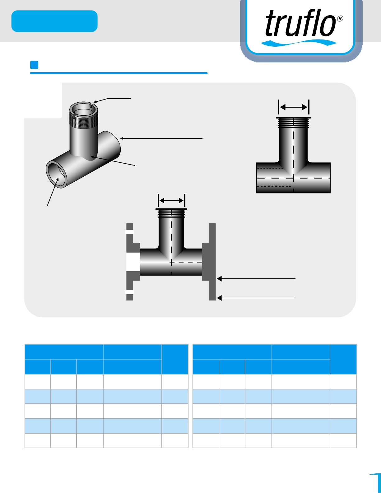
CPVC TEE FITTING (SCH80)
Remember to
Grease Flowmeter
& Fitting
Socket Weld
Schedule 80
Notch On Fitting
CPVC Tee Style
Ensure Notches
are Parallel to
Direction of Flow
1-1/4"
1-1/4"
CPVC Flange x 2
150 LB ANSI Flange
K-Factor - PULSE /LITER
Tee fitting (Unit:inch)
SIze DN Id
1/2"
3/4"
1"
1-1/4"
1-1/2"
Note : CPVC = PVC (for ISO SDR21 pipes and ASTM SCH80 PVC, CPVC Plastic Pipe)
*DIVIDE K factor by 3.8 to change to Pulse/Gallon
15
20
25
32
40
0.55
0.74
0.96
1.30
1.50
K-Factor
CPVC (SCH80)
213.40/
113.24/
88.08
49.63
41.27
Sensor
Length
T
T
T
T
T
Tee fitting (Unit:inch)
SIze DN Id
2"
2-1/2"
3"
4"
6"
50
65
80
100
150
1.90
2.30
2.90
3.83
3.80
K-Factor
CPVC (SCH80)
28.71
19.60
11.89
6.23
2.60
Sensor
Length
T
T
T
T
T1
DC Power Only
Find Quality Products Online at: [email protected]
www.GlobalTestSupply.com
10
Page 12
LS & LSS Series
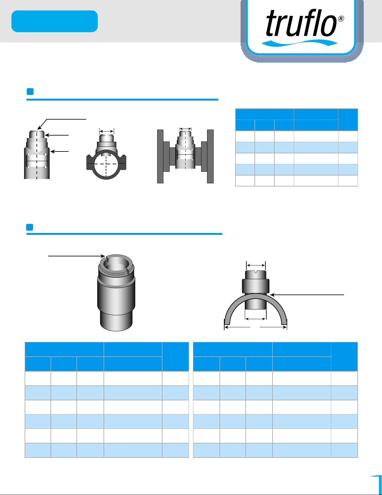
K FACTOR TABLES
CPVC+PP CLAMP SADDLES (SCH80)
Notch Ensure
Parallel to Flow
CPVC
PP
1-1/4"
1-1/4"
Note : CPVC=PVC (for ISO SDR21 Pipe and ASTM SCH80 PVC, CPVC Plastic Pipe)
*CHANGE TO PULSE/GPM DIVIDE K FACTOR BY 3.8
CPVC SOCKET WELD-ON ADAPTERS
Notch Ensure
Parallel to Flow
Clamp Saddles (Unit:In)
Size DN Id CPVC (SCH80)
2"
50
2-1/2"
65
3"
80
4"
100
6"
150
K-Factor (Pulse/Liter)
1.9
2.3
2.9
3.8
5.7
29.00
19.76
12.00
6.276
2.596
1-1/4"
Solvent Weld
(Use Weld-On 724
Cement P70 Primer)
Sensor
Length
T
T
T
T
T1
1.57"
Remember to
Grease Flowmeter& Fitting
Glue-On Adapters(Unit:inch)
SIze DN Id
2"
2-1/2"
3"
4"
6"
8"
DIVIDE K factor by 3.8 to change to Pulse/Gallon
*
50
65
80
100
150
200
1.9
2.3
2.9
3.8
5.7
7.0
K-Factor (Pulse/Liter)
CPVC (SCH80)
29.00
14.76
12.00
6.27
2.60
1.42
Sensor
Length
T
T
T
T
T
1
T
1
Glue-On Adapters(Unit:inch)
SIze DN Id
10"
12"
14"
16"
20"
24"
250
300
350
400
500
600
Id
9.5
11.3
12.4
15.1
19.0
21.0
K-Factor (Pulse/Liter)
CPVC (SCH80)
0.90
0.64
0.53
0.40
0.77
0.18
Sensor
Length
T
1
T
1
T
1
T
1
T
1
T
1
DC Power Only
Find Quality Products Online at: [email protected]
www.GlobalTestSupply.com
11
Page 13
LS & LSS Series
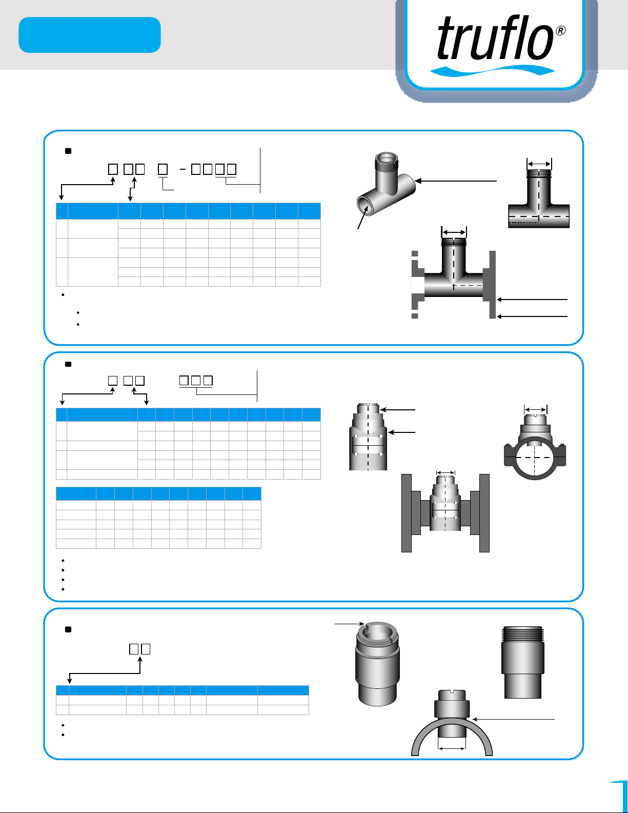
FITTING FOR LS & LSS SERIES PADDLE WHEEL FLOW METERS
CPVC TEE FITTING (SCH80)
MODEL :
Type
Tee fitting +ANSI
A
150 PSI Flanga
Tee fitting +ANSI
J
150 PSI Flanga
Tee fitting
T
Unit:Inch
CPVC tee fitting for ASTM SCH80 Pipe
Operating temperature: -22~+212°F(-30~+100°C)
CPVC +PP CLAMP SADDLES (SCH80)
MODEL :
Type
NO
CPVC+PP Clamp Saddles
A
+ANSI 150PSI Flange (CPVC)
C
CPVC+PP ClamD Saddles
NO Size DN Id L T H F
10
12
15
20
25
30
40
1-114"
1-112"
2/1/2"
NO
20
25
30
40
60
0
8
T
P = PVC
C = CPVC
1"
25
1.10
30
1.37
40
2"
3"
4"
SA -
Size
2-1/2"
1.69
50
2.12
65
2.55
80
3.14
100
3.93
DN Id D E W H F
2"
50
1.91
65
3"
4"
6"
8
2.29
80
2.86
3.78
100
5.70
150
00
"
2
05 = ½
07 = ¾
1.14
1.25
1.37
1.77
1.77
1.77
2.24
10 = 1
15 = 1 ½
20 = 2
30 = 3
40 = 4
3.11
3.26
3.26
3.60
3.87
4.33
4.96
6.45
7.30
8.03
8.72
10.27
10.27
13.12
Sensor
T
T
T
T
T
T
T
Socket Weld
Schedule 80
PVC
CPVC TEE STYLE
1-1/4"
O
4.01
4.54
5.03
5.72
6.73
6.73
9.35
1-1/4"
PVC
CPVC Flange x 2
ANSI lb Flange
150 LB ANSI Flange
020 = 2"
100 = 10"
030 = 3"
120 = 12"
040 = 4"
140 = 14"
060 = 6"
160 = 16"
2.48
2.95
3.54
4.33
6.29
4.25
4.60
5.11
6.22
8.46
3.11
3.46
3.85
3.74
4.56
080 = 8"
3.07
3.20
3.54
3.99
5.00
6.73
6.80
7.60
7.60
8.46
Sensor
T
T
T
T
1
T
T1
CPVC
PP
1-1/4"
1-1/4"
Part Num
SA080
SA100
SA120
SA140
SA160
Size
DN Id D E W H F
8"
200
6.81
10"
12"
14"
16"
225
250
315
400
8.85
9.4
9.84
11.1
7.87
8.80
9.91
12.4
15.7
6.81
8.80
9.9
9.84
11.1
4.80
5.57
6.06
7.28
9.33
Unit:Inch
Operating temperature:-22~+212°F(-30~+100°C)
Note1:SUS304 Bolt and Nut for PP Clamp Saddles
Note2:SLCS-/CXX (Drilling hole=40mm)
CPVC GLUE-ON ADAPTERS
MODEL : PG -
PIPE SIZE(DN)
NO
0.5"~4"(15~100)
6"~24"(150~600)
Unit:mm
Operating temperature:-22~+212°F(-30~+100°C)
L L1 L2 D1 D2 Drilling Hole
2.69
1.71
0.37
1.5
3.87
2.00
1.25
1.5
2.69
3.87
1.57
1.57
Sensor
T
T
T
T
T
Sensor Length
T1
Notch
T
Solvent Weld
(Use Weld-On 724
40mm
Cement P70 Primer)
Find Quality Products Online at: [email protected]
www.GlobalTestSupply.com
12
Page 14
LS & LSS Series
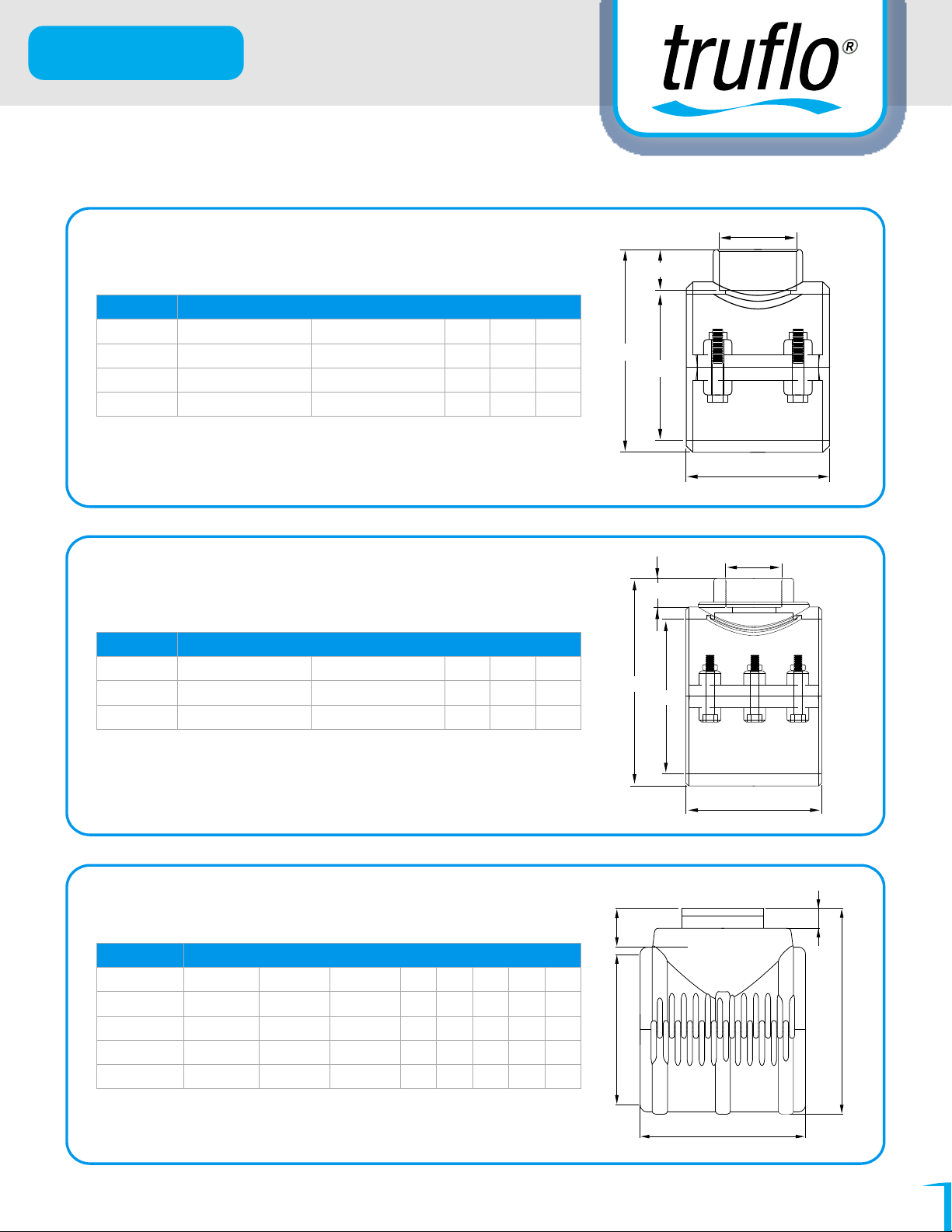
LS & LSS SERIES SADDLES DIMMENSIONS
C
D
129
STD Code Ø Pipe - C Weight (g) A B D
03144 2" (50) - 1 ¼" 306 70 99 23
03077 3" (90) - 1 ¼" 380 87 129 23
03082 4" (110) - 1 ¼" 503 104 155 23
128
STD Code Ø Pipe - C Weight (g) A B D
03096 6" (160) - 1 ¼" 1142 136 210 23
03100 8" (200) - 1 ¼" 1982 173 244 23
REINFORCED PP CLAMP SADDLE - 4 BOLTS SS316 & VITON
REINFORCED PP CLAMP SADDLE - 6 BOLTS SS316 & VITON
B
Ø
A
C
D
B
Ø
A
E
137
WEIGHT (g) STD Code C
03144 05203 283
03077 05066 308
03082 05213 370
03082 05484 474
Find Quality Products Online at: [email protected]
PP HINGED SLEEVE - 3 BOLTS SS316
Ø Pipe
10" (225)
12" (250)
14" (315)
16" (400)
Ø Outlet
1 ¼"
1 ¼"
1 ¼"
1 ¼"
A B
225 225
250 239
315 250
400 282
www.GlobalTestSupply.com
D
E
9
26
9
26
9
26
9
26
A
D
C
13
Page 15
LS & LSS Series
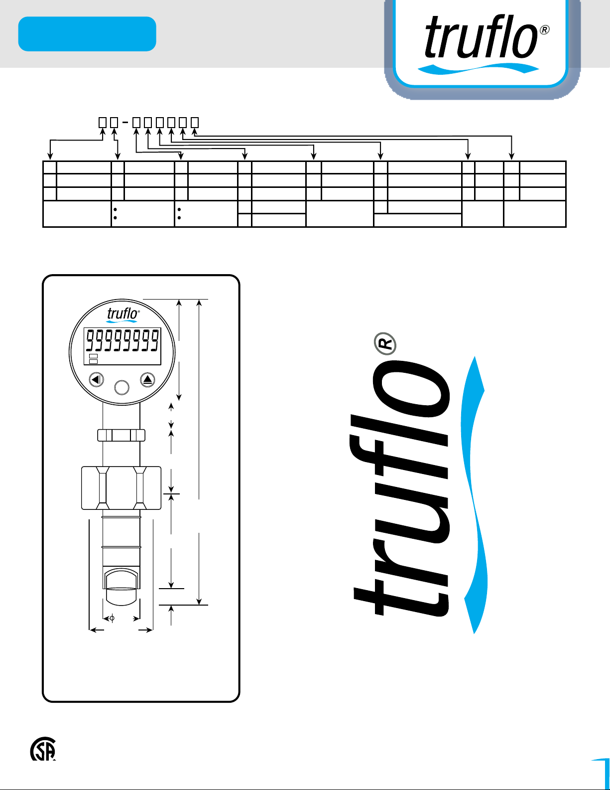
Sensor body
PPP
Natural PVDFV
Sensor Length Alarm Output
2.70 in (T)
0 None0
3.88 in (T1)
1
T (Pipe size 0.5" to 4") Relay Contact
T1(Pipe size 6"to 24")
Two Relay2
(DC 30V-7A)
1.DIMENSION (unit : inch)
P/O RATE GAL
OUT1
OUT2
D/O
RST
Liter/min
TOTAL TON M3/Hour
ALARM
D-S
ENT
FUNC
2.5
0.78
RS-485 OutputAnalog Output
None0
DC1~5V2
DC4~20mA2
NoneN
RS-485Y
Pulse Output
None
N
Synchronize lnput
I
Synchronize Totalizer
T
F
O-rings
FKM
Cable length
8M Standard
8
Customes
C
1.56
8.00 (TO)
9.20 (T1)
TO or T1
truflo LSS Series
0.47
1.05
1-1/4"
T = 68.5 mm (2.70")
T1 = 98.5 mm (3.88")
Specification may be modified without notice in advance.
Industry's Most Accurate Paddle Wheel Flow Meter
For More Information Visit www.truflosales.com
Find Quality Products Online at: [email protected]
www.GlobalTestSupply.com
14
Page 16
LS & LSS Series
Warranty Information
All warranty and non-warranty repairs being returned must include a fully completed Service
Form and goods must be returned to Truflo directly or to the distributor. Product returned
without a Service Form will not be warranty replaced or repaired.
Truflo Sensors are warranted out of box but not against any damage, due to Process or
Misapplication failures (e.g. High Temperature, Chemical Attack Due to Misapplication) or
Physical mishandling of product.
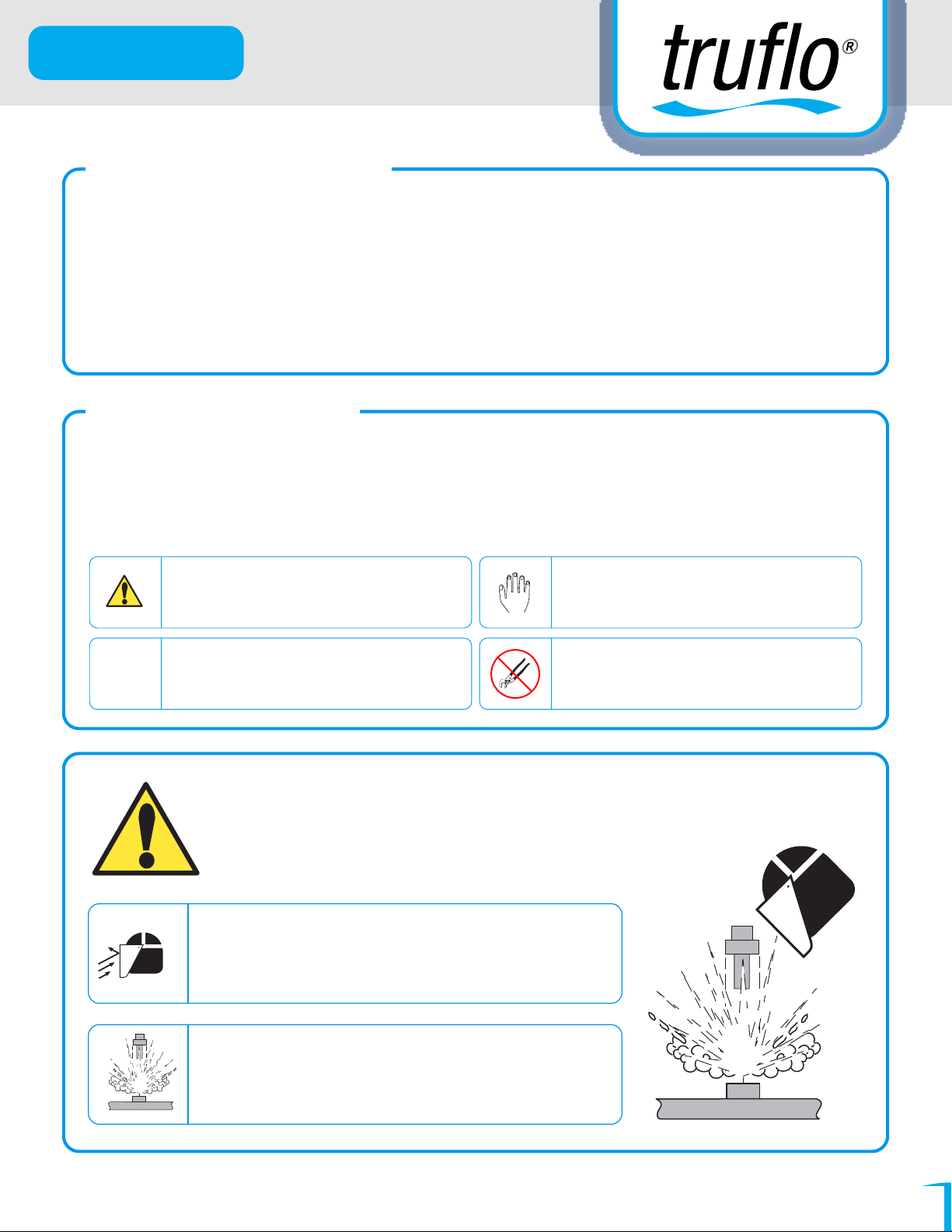
Safety Information
1. Depressurize and vent system prior to installation or removal.
2. Confirm chemical compatibility before use.
3. DO NOT exceed maximum temperature or pressure specs.
4. ALWAYS wear safety goggles or faceshield during installation and/or service.
5. DO NOT alter product construction.
Warning / Caution / Danger
Indicates a potential hazard. Failure to follow all
warnings may lead to equipment damage, injury, or
death
Note / Technical Notes
Highlights additional information or detailed
procedure.
WARNING!
Personal Protective Equipment (PPE)
Always utilize the most appropriate PPE during
installation and service of Signet products.
Hand Tighten Only
Overtightening may permanently damage product
threads and lead to failure of the retaining nut.
Do Not Use Tools
Use of tool(s) may damage product beyond repair
and potentially void product warranty.
Pressurized System Warning
Sensor may be under pressure, take caution to vent
system prior to installation or removal. Failure to do so
may result in equipment damage and/or serious injury.
DC Power Only
Find Quality Products Online at: [email protected]
www.GlobalTestSupply.com
15
 Loading...