

True GDM Series, GDT Series Technical & Service Manual

Technical Service Manual
(All Models)

Index
Page
Cabinet Installation and Set-Up _____________________________________________________4
Electrical Requirements______________________________________________________________5
Conductors and Circuits _____________________________________________________________6
Cabinet Installation and Set-Up Checklist ______________________________________________7
Cabinet Installation and Set-Up (Swing & Slide Doors) ___________________________________8
GDM/T - Series Freezers_____________________________________________________________9
Remote Condensing Unit____________________________________________________________10
Temperature Control Altitude Adjustment_____________________________________________11
Temperature Control Altitude Adjustment(new temp. control) ____________________________12
Defrost Controls ________________________________________________________________13-14
Preventative Maintenance __________________________________________________________16
Cabinet Maintenance Schedule_______________________________________________________17
Condenser Cleaning________________________________________________________________18
Refrigeration Section _______________________________________________________________20
Polyol Ester Lubricant - The CFC Report _____________________________________________21
Service Contractors: Attention Please _________________________________________________22
Basic Refrigeration - The Capillary Tube System _______________________________________23
The Refrigeration Cycle ____________________________________________________________24
True’s Remote System - How it Works ________________________________________________25
Basic Refrigeration - Control of Liquid Refrigerant Floodback... __________________________26
General Maintenance & Repairs ___________________________________________________28
Top Removal for TBB and TDD Units_________________________________________________29
Top Removal forTD and T-GC Units _________________________________________________30
TPPCountertop Replacement Instructions_____________________________________________31
Top Removal for Various Coolers - TSSU, TWT,TUC ___________________________________32
Top Removal forTRCB 50 and 79 ____________________________________________________33
End Cap Replacement-T-Series Swing Door _________________________________________34-35
Side Panel Replacement - GDM Series ________________________________________________36
Side Panel Replacement - GDM-33C-PT_______________________________________________37
Floral Case Baffle Installation _______________________________________________________38
GDM-23FC Mirror Retrofit Kit______________________________________________________39
Undercounter Refrigerator/Freezer Perimeter Heater Wire Replacement ___________________40
GDM & T-Series Freezer Perimeter Heater Wire Replacement____________________________41
TD-Series and Glass Chillers ________________________________________________________42
Temperature Control Replacement for Cabinets Larger than 1/3 HPCompressors ________43-47
Temperature Control Change-Out - GDM _____________________________________________48
Temperature Control Change-Out - GDM & T-Series____________________________________49
Replacing Temperature Controls in GDM-7, GDM-10, & GDM-12 models__________________50
Surge Protector’s for the GDM-Series ______________________________________________51-52
Door and Lock Repair ______________________________________________________________54
Glass Insert - Slide Door ____________________________________________________________55
Slide Door Instruction - To improve slide door closing___________________________________56
Wiper Gasket Installation ___________________________________________________________57
Removal and Installation of GDM-Swing Door ______________________________________58-59
Torsion Spring Replacement - Swing Door __________________________________________60-61
IDLLamp Replacement ____________________________________________________________62

Index
Page
Glass Insert - Swing Door ________________________________________________________63-64
Glass Insert Gas Release (High Altitude Installation) ____________________________________65
GDM & T-Series IDLGlass Insert Replacement ________________________________________66
Replacement of Door Frame Heater on IDL Freezer Doors _______________________________67
IDL Door Wire Harness Replacement______________________________________________68-69
Shimming the Glass Insert________________________________________________________70-71
Lock Installations - GDM Single Swing Door (GDM-23/26)_______________________________72
Barrel Lock Installation (GDM Slide DoorModels) _____________________________________73
Slide Barrel Lock (Top View) ________________________________________________________74
Slide Barrel Lock (Front View)_______________________________________________________75
Lock Installation (GDM-5 & GDM-5PT Swing Door Models) _____________________________76
Ratchet Lock & Plastic Door Stop - Slide Door ______________________________________77-78
Lock Installation - TD Models _______________________________________________________79
General Instructions________________________________________________________________80
Overshelf Option - TSSU, TWT, TUC_________________________________________________81
Installing The Crumb Catcher _______________________________________________________82
Field Installing The TSSU Series 19” Cutting Board_____________________________________83
Anchoring the TSSU Hood Cover ____________________________________________________84
Installing the TTPSeries Service Shelf ________________________________________________85
Field Installing the TPPService Shelf _________________________________________________86
Sneezeguard Option - TSSU _________________________________________________________87
Castor and Leg Frame Installation ___________________________________________________88
GDM-33C-PT Castor Mounting Assembly _____________________________________________89
TDD-1 CO
TDD-2,3,4 (and Club Top models) CO2 Knock-out ______________________________________91
Vandal Panel Installation for a GDM-33CPT-54 ________________________________________92
Vandal Panel - GDM-69 __________________________________________________________93-94
Troubleshooting ____________________________________________________________________96
Calibrate Temperature Control____________________________________________________97-98
Troubleshooting and Service Chart _______________________________________________99-100
Capillary Tube Replacement Instructions - Upright GDM/T-Series Equipment__________101-102
Refrigeration Trouble Shooting Chart - Refrigerator________________________________103-104
Refrigeration Trouble Shooting Chart - Freezer ____________________________________105-106
Capillary Tube Replacement Instructions - Refrigerators and Freezers ____________________107
Field Troubleshooting__________________________________________________________108-110
Troubleshooting Fluorescent Lighting Circuits
GDM & T Series Coolers IDLConnector _____________________________________________112
Equipment Care and Cleaning ____________________________________________________114
Cleaning Your Cabinet_____________________________________________________________115
Stainless Steel Equipment Care and Cleaning (NAFEM)_____________________________116-120
Knock-out______________________________________________________________90
2
Rapid Start, Electric, and Preheat Fluorescent Light Circuits ____________________________111

4
Please read these instructions. Failure to follow maintenance guidelines
may result in a n o n - w a r r a n t e d service call.
CABINET
INSTALLATION
AND SET-UP

5
ELECTRICAL REQUIREMENTS
There are several factors that will affect the proper operation of your True unit. A m o n g
these factors, the electrical installation is the most important and should always be
checked before connecting your True cabinet as follows:
1. Make sure the circuit is dedicated exclusively to your True unit.
2. Make sure the electrical installation complies with national, state, and local codes.
3. Make sure the circuit is properly ground.
4. Check circuit for proper voltage at receptacle (+/-10% 115 Volt)
(- 5% + 10% 208/230 Volt)
5. Make sure that the wire gauge and breaker sizes are correct and comply with the min-
imum allowance for voltage drops
WARNING: FAILURE TO COMPLY WITH THESE REQUIREMENTS MIGHT
R E S U LT IN PERSONAL I N J U RY AND (OR) PROPERTY DAMAGE, AND W I L L V O I D
WA R R A N T Y.

6
CONDUCTORS AND CIRCUITS
Wi re Gauge for 2% Voltage Drop in Supply Circ u i t s
115 Vo l t Distance In Feet To Center of Load
A m p s 2 0 3 0 4 0 5 0 6 0 7 0 8 0 9 0 1 0 0 1 2 0 1 4 0 1 6 0
2 1 4 1 4 1 4 1 4 1 4 1 4 1 4 1 4 1 4 1 4 1 4 1 4
3 1 4 1 4 1 4 1 4 1 4 1 4 1 4 1 4 1 4 1 4 1 4 1 4
4 1 4 1 4 1 4 1 4 1 4 1 4 1 4 1 4 1 4 1 2 1 2 1 2
5 1 4 1 4 1 4 1 4 1 4 1 4 1 4 1 2 1 2 1 2 1 0 1 0
6 1 4 1 4 1 4 1 4 1 4 1 4 1 2 1 2 1 2 1 0 1 0 1 0
7 1 4 1 4 1 4 1 4 1 4 1 2 1 2 1 2 1 0 1 0 1 0 8
8 1 4 1 4 1 4 1 4 1 2 1 2 1 2 1 0 1 0 1 0 8 8
9 1 4 1 4 1 4 1 2 1 2 1 2 1 2 1 0 1 0 8 8 8
1 0 1 4 1 4 1 4 1 2 1 2 1 0 1 0 1 0 1 0 8 8 8
1 2 1 4 1 4 1 2 1 2 1 0 1 0 1 0 8 8 8 8 6
1 4 1 4 1 4 1 2 1 0 1 0 1 0 8 8 8 6 6 6
1 6 1 4 1 2 1 2 1 0 1 0 8 8 8 8 6 6 6
1 8 1 4 1 2 1 0 1 0 1 0 8 8 8 8 8 8 5
2 0 1 4 1 2 1 0 1 0 8 8 8 6 6 6 5 5
2 5 1 2 1 0 1 0 8 8 6 6 6 6 5 4 4
3 0 1 2 1 0 8 8 6 6 6 6 5 4 4 3
3 5 1 0 1 0 8 6 6 6 5 5 4 4 3 2
4 0 1 0 8 8 6 6 5 5 4 4 3 2 2
4 5 1 0 8 6 6 6 5 4 4 3 3 2 1
5 0 1 0 8 6 6 5 4 4 3 3 2 1 1
230 Vo l t s Distance In Feet To Center of Load
A m p s 2 0 3 0 4 0 5 0 6 0 7 0 8 0 9 0 1 0 0 1 2 0 1 4 0 1 6 0
5 1 4 1 4 1 4 1 4 1 4 1 4 1 4 1 4 1 4 1 4 1 4 1 4
6 1 4 1 4 1 4 1 4 1 4 1 4 1 4 1 4 1 4 1 4 1 4 1 2
7 1 4 1 4 1 4 1 4 1 4 1 4 1 4 1 4 1 4 1 4 1 2 1 2
8 1 4 1 4 1 4 1 4 1 4 1 4 1 4 1 4 1 4 1 2 1 2 1 2
9 1 4 1 4 1 4 1 4 1 4 1 4 1 4 1 4 1 2 1 2 1 2 1 0
1 0 1 4 1 4 1 4 1 4 1 4 1 4 1 4 1 2 1 2 1 2 1 0 1 0
1 2 1 4 1 4 1 4 1 4 1 4 1 4 1 2 1 2 1 2 1 0 1 0 1 0
1 4 1 4 1 4 1 4 1 4 1 4 1 2 1 2 1 2 1 0 1 0 1 0 8
1 6 1 4 1 4 1 4 1 4 1 2 1 2 1 2 1 0 1 0 1 0 8 8
1 8 1 4 1 4 1 4 1 2 1 2 1 2 1 0 1 0 1 0 8 8 8
2 0 1 4 1 4 1 4 1 2 1 2 1 0 1 0 1 0 1 0 8 8 8
2 5 1 4 1 4 1 2 1 2 1 0 1 0 1 0 1 0 8 8 6 6
3 0 1 4 1 2 1 2 1 0 1 0 1 0 8 8 8 6 6 6
3 5 1 4 1 2 1 2 1 0 1 0 1 0 8 8 8 6 6 6
4 0 1 4 1 2 1 0 1 0 8 8 8 6 6 6 5 5
5 0 1 2 1 0 1 0 8 8 6 6 6 6 5 4 4
6 0 1 2 1 0 8 8 6 6 6 6 5 4 4 3
7 0 1 0 1 0 8 6 6 6 5 5 4 4 3 2
8 0 1 0 8 8 6 6 5 5 4 4 3 2 2
9 0 1 0 8 6 6 6 5 4 4 3 3 2 1
1 0 0 1 0 8 6 6 5 4 4 3 3 2 1 1

7
CABINET INSTALLATION AND SET UP CHECKLIST
1) Make sure cabinet is plugged into dedicated outlet. Before plugging in cabinet check to make sure
voltage is adequate for your cabinet. Do not use an extension cord, this will void cabinet
w a r r a n t y.
2) Follow installation instructions for your specific cabinet. Each cabinet is shipped with specific
installation and set up instructions. It is very important to read all information sent with your new
cabinet
3) Make sure shipping blocks (slide doors) and door support brackets (swing doors) are removed.
Doors will not function correctly if this step is not followed.
4) Make sure that your cabinet is leveled correctly. Follow specific instructions with your cabinet and
use castor shims were they are needed. Make sure that legs and castors are installed per instructions. If directions are not followed this may cause premature unwarranted failure of cabinet legs
or castors. If your cabinet is not level this can cause performance problems that will not be covered as warranty repairs.
5) When cabinet is set in its final location, make sure the specific clearance guidelines are followed.
These are very important for ventilation in the condensing unit area. If not followed can cause
premature compressor failure.
6) Follow altitude adjustment for temperature control if applicable.
7)
IF YOU HAVE ANY QUESTIONS ABOUT SET UP OR INSTALLATION OF YOUR
NEW CABINET PLEASE CALL OUR TECHNICAL SERVICE DEPARTMENT AT 1800-325-6152.
CABINET INSTALLATION AND SET UP CHECKLIST
8
INSTALLATION INSTRUCTION
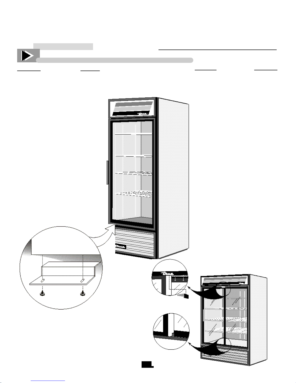
CABINET INSTALLATION AND SET-UP (SWING & SLIDE DOORS)
SWING DOORS
A. Remove all other tape securing
the doors to the cooler. Remove
the blue foam blocks approximately 1”x3”x1” (2.5 x 7.6 x 2.5 cm)
that are between the door and the
cooler. One foam block is located
on each side of the door frame. (left
and right).
NOTE
Your True Merchandiser has been
secured for safe shipping. During
installation, it is necessary to remove
the door support bracket.
SLIDE DOORS
A. Remove all transparent tape on the
door area. Remove the foam blocks in
top channel in front on the right door
approximately 1”x1”x20” (2.5 x 2.5 x
50 cm).
B . Remove both plastic brackets
secured by tape from under the left
door.
C. Open the left door.
D. Remove the foam block from the
top channel behind the left door.
B. Remove the two phillips screws
that secure the bracket to the door.
(see figure 1).
C. Remove bracket and save for
future shipping.
D. Replace screws securely into door.
E. Remove both plastic brackets from
under the right door (see figure 2).
NOTE
Door packing materials should NOT
be removed until cooler is placed on
location.
TRANSPORTATION OF THE
COOLER WITHOUT THE DOOR
PACKING MATERIALS IN
PLACE CAN RESULT IN DAM-
AGE TO DOORS, DOOR
ROLLERS AND V-TRACK
(figure 2)
(figure 1)
INSTALLATION INSTRUCTION
9
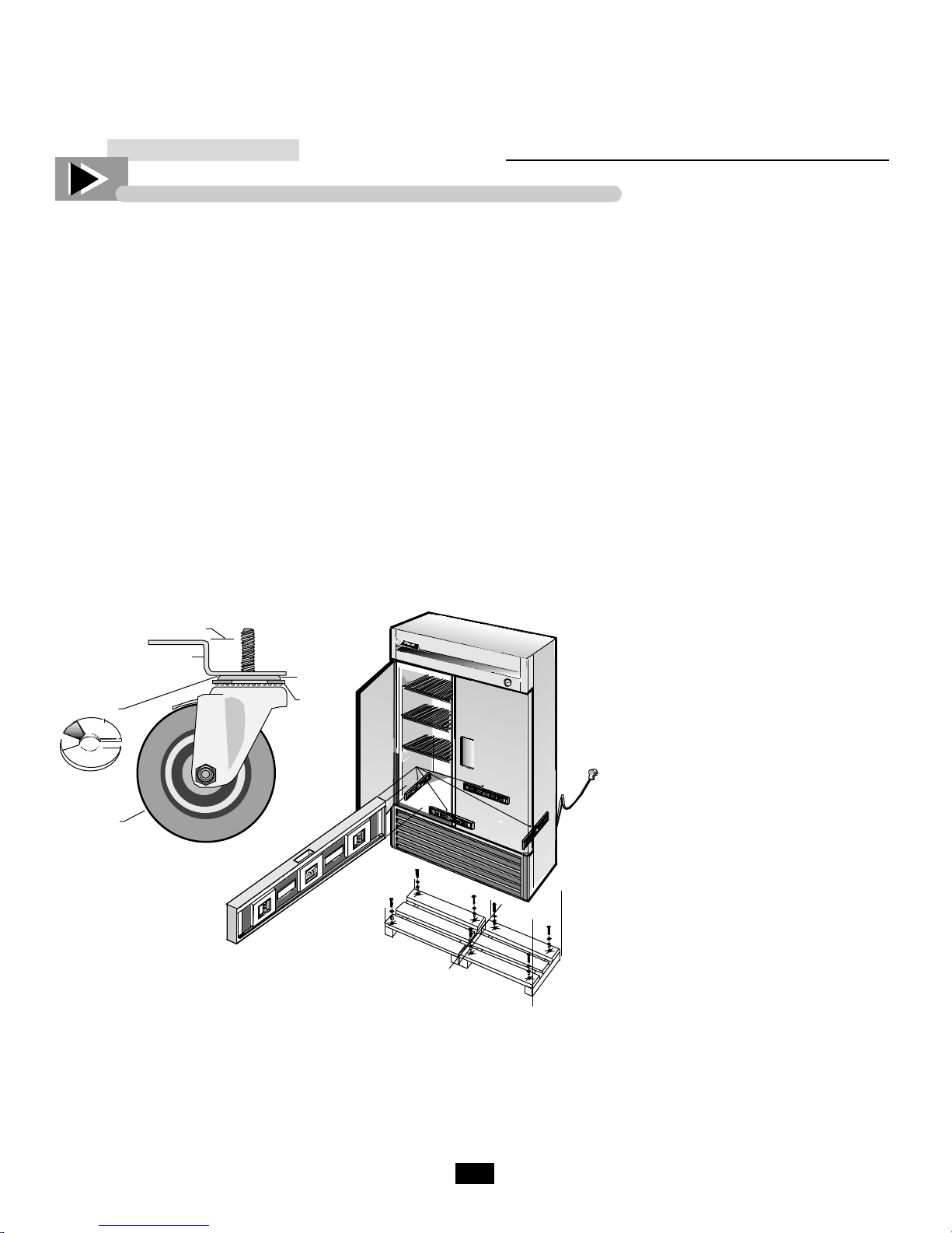
GDM / T-Series Freezers
______ Installing Castors _______
Install castors in the bottom rail assembly
on the underside of the cooler. Castors
with brakes should be installed in front.
To obtain maximum strength and stability
of the unit, it is important that you make
sure each castor is secured with a 3/4"
(19mm) open-end wrench. The bearing
race on the castor must make firm contact
with the rail.
______ Installing Leg Levelers _______
Screw leg levelers into the four corners of
the lower rail assembly (larger models
include levelers centered front and back
also).
CAUTION
To avoid damage to lower rail assembly,
raise unit slowly and carefully to upright
position.
LEVELING
A. Set unit in its final location. Be sure
there is adequate ventilation in your room.
Under extreme heat conditions, (100°F+,
38°C+), you may want to install an exhaust
fan.
Warning
Warranty is void if
ventilation is insuff i c i e n t .
B. Proper leveling of your True cooler is
critical to operating success. Effective
condensate removal and door operation
will be effected by leveling.
C . The cooler should be leveled front to
back and side to side with a level (see figure
4). Place the level in the interior floor of the
unit in the four positions illustrated.
For Castored Models:
Four shims have been provided in warranty packet for leveling castored units posi-
tioned on uneven floors. Shims must be
positioned between rail end and bearing
race. (see figure 3).
If the cabinet is not level use a 3/4" (19mm)
open-end wrench to turn the anchoring bolt
under the bearing race counter-clockwise until
the cabinet is level.
Install the desired number of shims, making
sure the slot of the shim is in contact with the
threaded stem of the castor.
If more than one shim is used, turn the slot at
a 90° angle so they are not in line.
Turn the anchoring bolt clockwise with a 3/4"
(19mm) open-end wrench to tighten and
secure the castor.
Leg Levelers For GDM Models:
If the cabinet is not level adjust leg levelers by
first relieving weight to leveler and adjusting
by either hand or wrench. Repeat with all leg
levelers until cabinet is level in all directions.
D . Ensure that the drain hose or hoses are
positioned in the pan.
I M P O R TA N T
Make certain the metal strap holding the
c o m p re s s o r during shipment is re m o v e d .
F a i l u re to cut strap could result in excessive
noise and vibration (fre e z e r ) .
E. Free plug and cord from inside the
figure 3.
l o w e r re a rof the cooler(do not plug in).
F. The unit should be placed close
enough to the electrical supply so that
extension cords are never used.
figure 4.
Warning
Compressor warranties are void if the
unit is more than 6-1⁄2 ft. (2m) from plugin connection.

10
INSTALLATION INSTRUCTION
Remote Condensing Unit
For cabinet installation, use installation instructions with cabinet.
Receiving: Upon receiving this
piece of equipment remove all
outer packaging and inspect for
concealed damage. If damage is
found, indicate such on the carriers
Bill of Lading for claim to be filed.
In order to minimize damage to this
equipment, it is recommended that
the packaging remains in place
until it is in its final location.
Condensing units located indoors
or in confined areas must have adequate ventilation. Condensing units
require 1000 cfm of air per ton of
refrigeration.
True Manufacturing Company
strongly recommends the use of
compressor crankcase heaters and
headmaster valves be used at all
times with a remote compressor
unit. Not using these components
may void the compressor warranty.
Refrigerant Lines: All refrigerant piping should be ACR type. It
is recommended that all brazed
joints be made with “hard solder”
such as Silphos or Unibraze.
Solder such as 95-5 or other soft
solders are not recommended.
All suction lines must be insulated, with at least 1/2” wall insulation. Keep all lines as short as possible.
Always pitch suction lines downward in the direction of flow.
Generally 1/2” pitch for each 10 ft.
of line is adequate for good oil
return. Field installation vibration
eliminators should be field installed
parallel with the compressor crank
shaft and as close to the compressor
as possible.
Leak Check and Evacuation:
After all refrigerant line connections
have been complete, the entire system should be leak checked. This
includes field and factory connections. Charge system with refrigerant
vapor and add enough nitrogen to
raise pressure to 150 PSIG maximum.
Leak check the entire system.
Make repairs as necessary.
Evacuation Process: To obtain
the proper level of dehydration in the
refrigeration system, a vacuum of at
least 500 microns must be drawn. Do
not use the system’s compressor as a
vacuum pump and do not operate
compressor while system is in a vacuum.
Open all system service valves to
discharge any pressure in the system.
Connect vacuum pump to high and
low side of system. Pull vacuum.
Break the vacuum with system
refrigerant. Pull vacuum again, down
to 500 microns or lower.
Shut valves before charging.
Charging Process: When initially
charging a system that is in a vacuum,
liquid refrigerant can be added directly into the receiver tank w i t h o u t
compressor running.
If you have difficulty charging the
correct amount of refrigerant into the
system you may start the system to
complete the charging process.
Add the correct amount or until the
sight glass indicates a full charge,
with a clear window, bubbles indicate
more refrigerant is required. Care
should be taken not to overcharge the
system at this point. The evaporator
fans must be operational while charging; cooler fans must run continuously, freezer fans will be delayed by the
fan control. Make sure freezer fans
are running during final charg i n g
process.
Keep a close check on suction and
discharge pressures. After system has
stabilized, check for excessive liquid
floodback to the compressor. If
flooding occurs (less than 8˚ superheat in freezers, 12˚ in coolers) adjust
expansion valve Clockwise, 1/2 a
turn at a time, recheck before leaving
installation.
Check full load amps on the compressor, this can be found on the compressors nameplate, Check compressor oil level. Normal charge is indicated by 1/2 of the sight glass having
oil in it.
Final Check: Check high and low
pressure control settings. Set thermostat to desired cabinet temperature.
Check defrost timer settings (if applicable). Check voltage, this must be
100% of the nameplate rated voltage
for operation. Anything more or less
should be corrected immediately.
Replace all service valve caps and
secure all unit covers.
11
This scale may be
used as a guide
for measuring
degrees of rotation required for
altitude correction.
The arrows indicate
direction of screw
rotation.
REQUIRED TOOLS
• Phillips Head Screwdriver
• Hex Head Driver
• Jewelers Screwdriver
IMPORTANT
Upright models ordered with "High
Altitude" temperature controls
are pre-calibrated and do not
require adjustment.
___________ STEP 1 ___________
Unplug the cooler.
___________ STEP 2 ___________
Turn the temperature control to the "9"
position.
___________ STEP 3 ___________
Remove the screws that secure the
mounting plate to the evaporator top.
("A") See figure 1.
___________ STEP 4 ___________
Pull control down gently from housing.
___________ STEP 5 ___________
Turn screws counterclockwise (CCW)
See Chart and figure 2.
___________ STEP 6 ___________
Reassemble to cooler housing and
return the temperature control to the
"5" position.
INSTALLATION INSTRUCTION
TEMPERATURE CONTROL ALTITUDE ADJUSTMENT
Figure 1
Chart
CCW
Adjustment
(based on 360°/
Height complete turn)
2000' 42°
3000' 78°
4000' 114°
5000' 150°
6000' 186°
7000' 222°
8000' 258°
9000' 294°
10,000' 330°
Figure 2
12
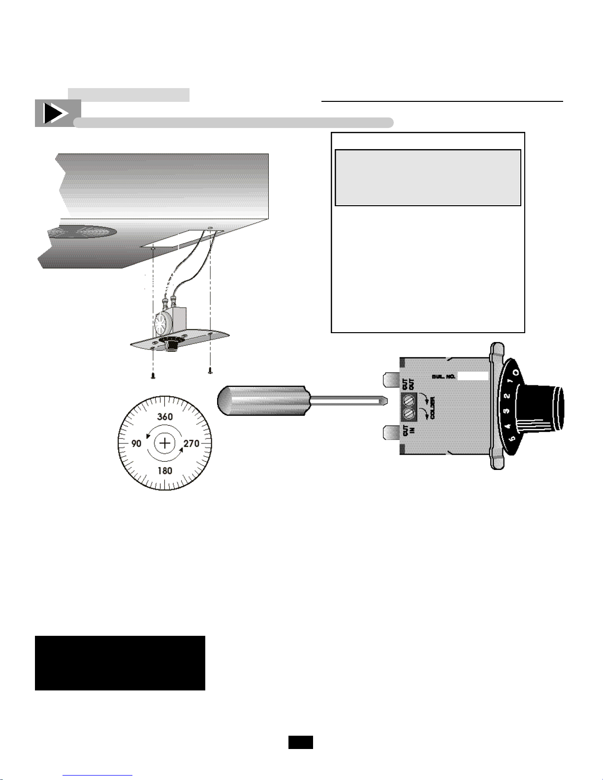
INSTALLATION INSTRUCTION
Danfoss Temperature Control Adjustment for High Altitude Applications
Terms:
Cut-out - Temperature sensed by the
controller that shuts the compressor
off.
Cut-in - Temperature sensed by the
controller that turns the compressor on.
Instructions:
___________ STEP 1 ___________
Mechanical temperature controllers are
affected when functioning at high altitude. The cut-in and cut-out temperatures will be colder than when the controller function closer to sea level.
___________ STEP 2 ___________
For installations above 2,000 ft., it may
be necessary to “warm-up” the set
points. To make the adjustment, insert
the appropriate tool in each adjustment
screw and turn 1/4 of a revolution
clock-wise (to the right). This procedure will adjust both the cut-in and
cut-out about 2˚F warmer.
___________ STEP 3 ___________
Make sure to re-connect the pink wires
to the proper spade terminal when
re-installing.
Cut-out Adjustment Screw
Allen (5/64” or 2 mm.)
Cut-in Adjustment
Screw Torx (T-7)
Compressor Connection (pink)
Compressor Connection (pink)
13
Recommended Defrost Settings
True Manufacturing has factory set your defrost time clock to a recommended time and duration defrost
scenario. All refrigeration equipment operating below 30˚F will accumulate frost on the evaporator coil
and will require routine defrost. Your True equipment has been designed for three defrost periods (8:00
a.m., 12:00 p.m. and 4:00 p.m.).
If you decide to deviate from these defrost time settings please follow the procedures and adjustment
below.
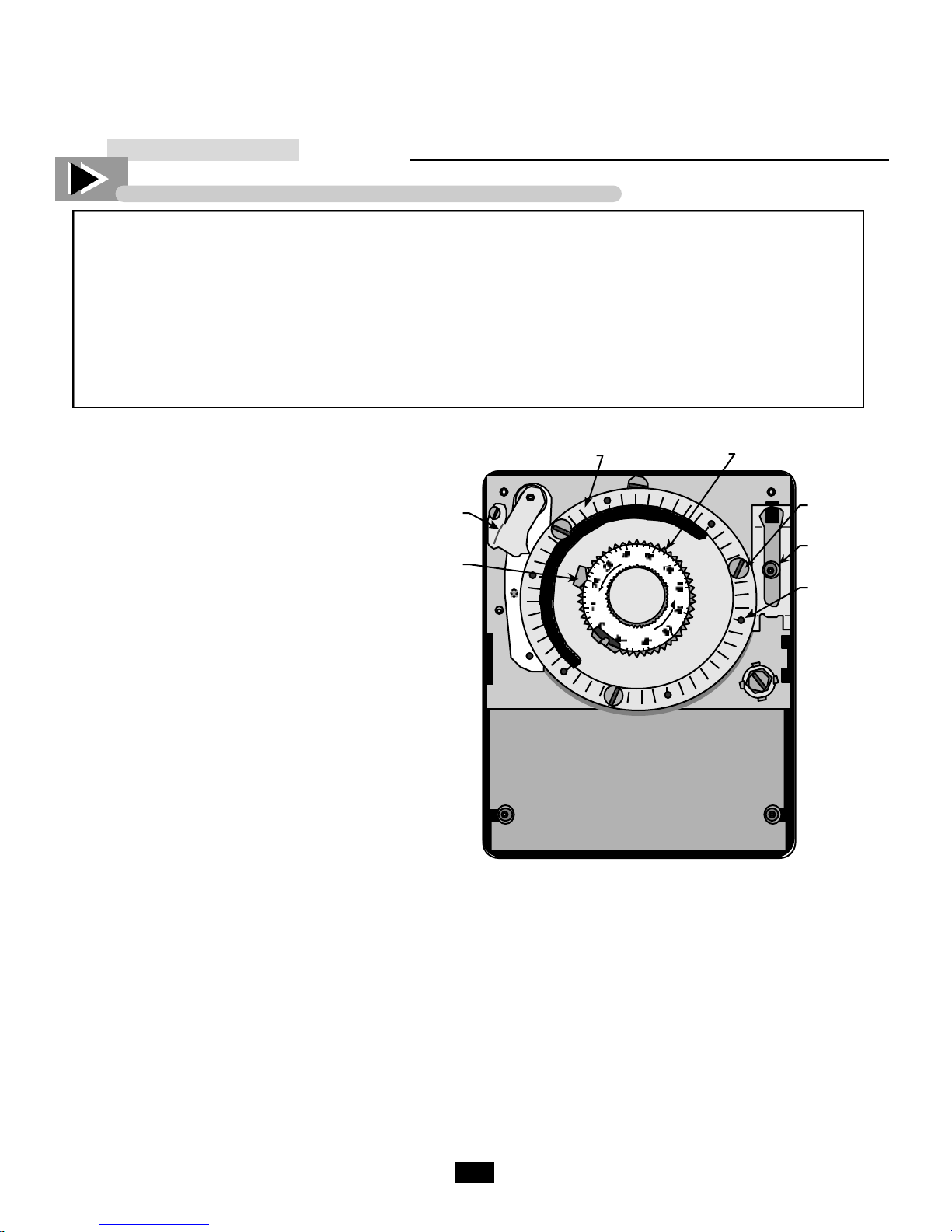
DEFROST CONTROLS
Defrost Time Clock Adjustment
REQUIRED TOOLS
Graduated
Time Disk
Adjusting
Knob
• Slotted Screwdriver
Locating The Defrost Timer
Take off lower grill assembly by removing
four (4) corner screws.
Single door models:
Defrost timer is located in the lower right
corner behind the louvered grill.
Two door models:
Defrost timer is located in the middle of
the cabinet, behind the louvered grill.
Timer is mounted to the left of the centered
ballast box.
Three door models:
Defrost timer is located on the left upright
post behind the louvered grill.
Adjusting The Defrost Control
(time initiated, temperature terminated)
Your True freezer contains a defrost
system that is temperature terminated,
however the time clock has been designed
with a time termination back-up so that the
defrost period will not exceed twenty
minutes. While True recommends 3
defrost periods not to exceed 20 minutes
the procedure below should be followed to
customize your specific needs.
Time
Indicator
Duration
Indicator
Warning
Always follow the manufactures
recommended settings when program-
ming the amount and duration of the
defrost cycles.
___________ STEP 1 ___________
Referencing the outer graduated time disk,
position the current time of day to align
with the “TIME” indicator. To move the
graduated time disk, grasp the adjusted
knob and turn counter clockwise until the
current time of day aligns with the “TIME
indicator.
Trip Pin
Extra Trip
Pin
Trip Pin
Hole
___________ STEP 2 ___________
In order to program the time to begin the
defrost cycle, insert threaded trip pins into
the graduated time disk hole that
corresponds to your customized defrost
needs.
___________ STEP 3 ___________
True recommends a 20 minute defrost
cycle three times per day. Changing the
recommended duration requires pressing
down and sliding the copper duration
indicator.
14
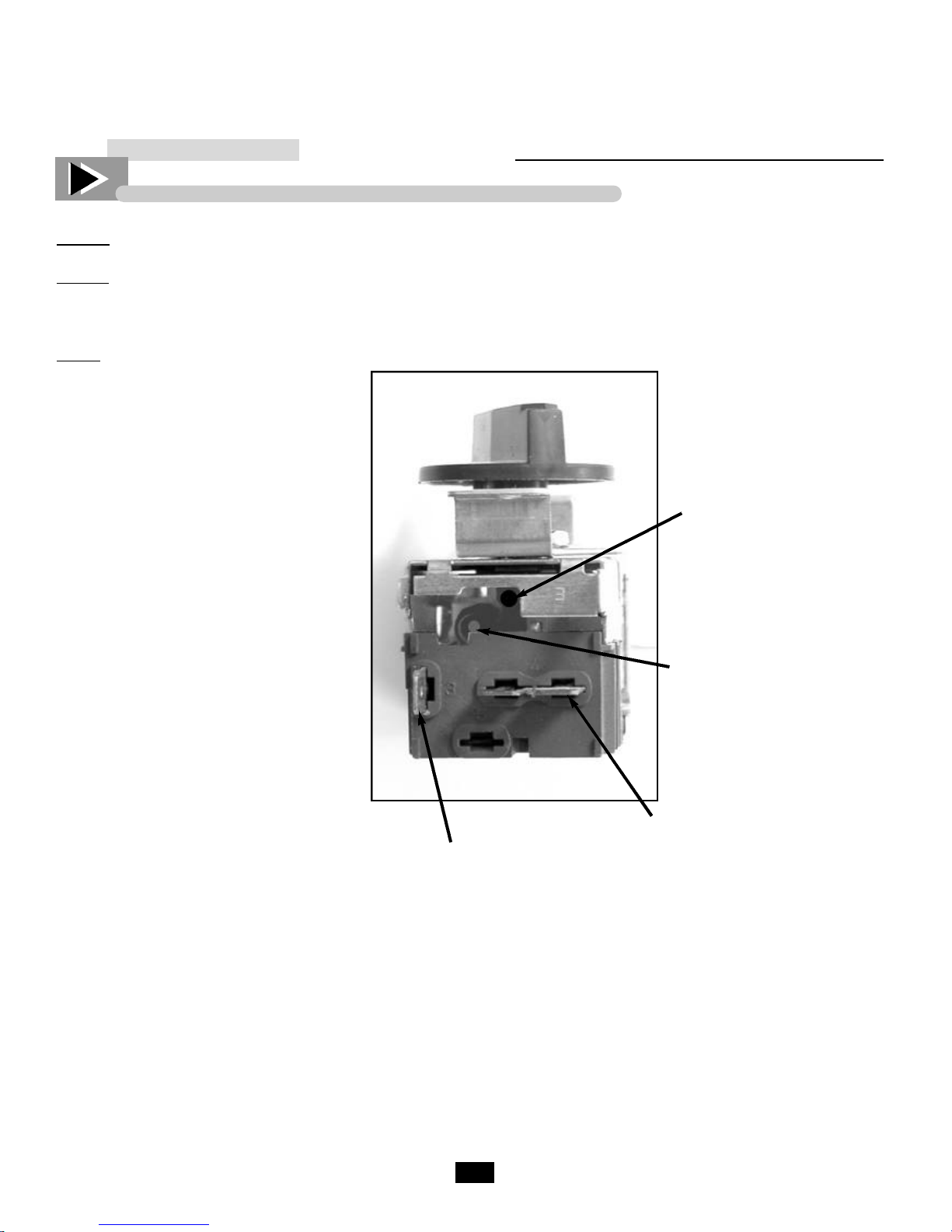
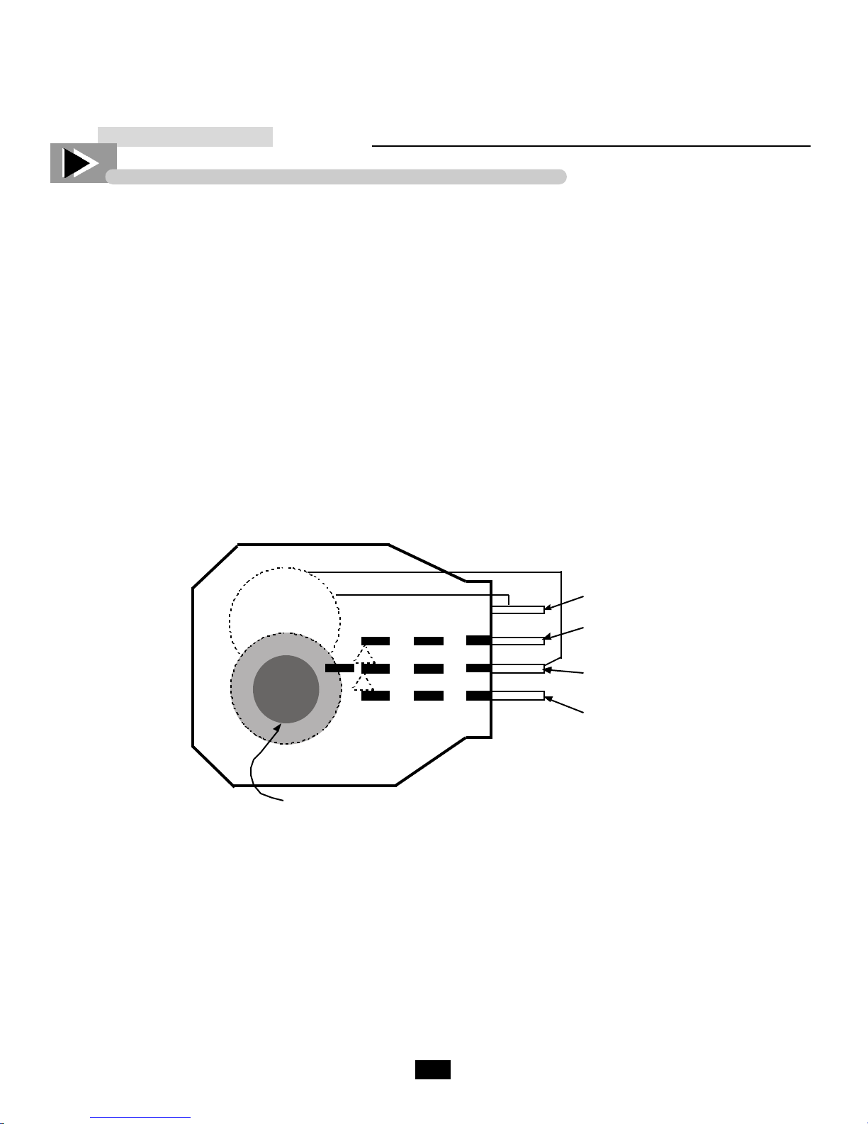
2. TIME INITIATED, TIME TERMINATED
Like in the time initiated, temperature terminated controls; these systems have a temperature sensor that will
disconnect the heaters to keep the cabinet from over heating. However it won’t restart the freezing cycle until
the control completes the factory set time, which in our case is usually 20 minutes. These systems are also
equipped with temperature sensors to delay the fan motors once the defrost cycle has been completed, to prevent the circulation of warm air inside the cabinet.
To adjust the defrost cycle time there is only one possible adjustment; Once the cabinet has reach the design
temperature, pick the time of the day that you want the unit to defrost. T urn the actuating gear clockwise until
the contacts change position initiating the defrost c y c l e .
MOTOR
DEFROST CONTROLS
3 Line
4 Compressor
1 Comun
2 Heaters
Actuating Gear
Common

Notes

16
Please read these instructions. Failure to follow maintenance
guidelines may cause a n o n - w a r r a n t e d cabinet repair service.
PREVENTATIVE
MAINTENANCE

17
CABINET MAINTENANCE SCHEDULE
MONTHLY
1. Check product temperature.
2. Brush off condenser coil.
3. Inspect lamps and lamp holder connections.
QUARTERLY
1. Check physical condition of condenser coil and evaporator coil (straighten fins if necessary.
2. Blow out condenser coil with compressed air.
3. Brush off evaporator coil if needed.
4. Check physical condition of gaskets and also make sure they are sealing correctly.
YEARLY
1. Check operation of all moving parts (fan motors, doors, defrost timers, & IDL door cords)
2. Check all electrical connections, make sure they are all tight and crimps in good condition.
3. Check defrost timer contacts, make sure they are not pitted.
4. Check rear condenser coil screen (clean if necessary).
CABINET MAINTENANCE SCHEDULE
Monthly, Quarterly, and Yearly
GENERAL MAINTENANCE
18
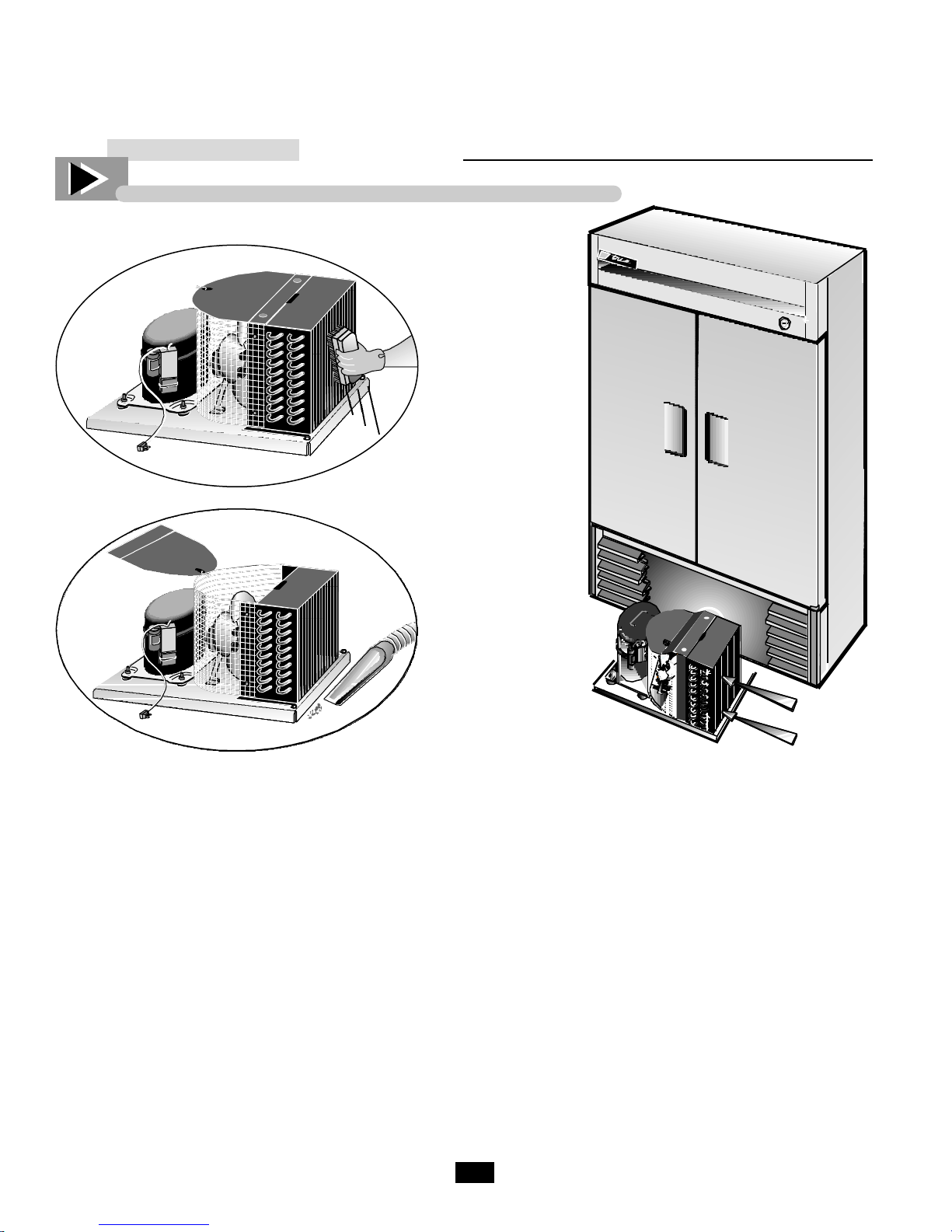
CONDENSER CLEANING
Step 4
Step 6
REQUIRED TOOLS
• Phillips Screwdriver
• Stiff Bristle Brush
• Adjustable Wrench
____________ STEP 1 ____________
Disconnect power to unit.
____________ STEP 2 ____________
Take off lower grill assembly by removing
four (4) corner screws.
____________ STEP 3 ____________
Remove bolts anchoring compressor
assembly to frame rails and carefully slide
out. (tube connections are flexible)
____________ STEP 4 ____________
Clean off accumulated dirt from condensing
coil with a stiff bristle brush.
____________ STEP 5 ____________
Lift cardboard cover above fan at plastic
plugs and carefully clean condenser coil
and fan blades.
____________ STEP 6 ____________
After brushing condenser coil vacuum dirt
from coil, and interior floor.
____________ STEP 7 ____________
Replace cardboard cover. Carefully slide
compressor assembly back into position
and replace bolts. When reinstalling
condensing unit becareful not to crimp
or damage the tubing between the condensing unit and the cabinet.
____________ STEP 8 ____________
Reinstall louver assembly onto unit with
appropriate fastener and clips. Tighten all
screws.
____________ STEP 9 ____________
Connect unit to power and check to see if
compressor is running.

Notes

20
In this section you can find information that is helpful for the
customer and the service technician to help you understand how
our refrigeration system works along with how to diagnose
and correct any problems that might arise.
REFRIGERATION
SECTION

21
Polyol Ester Lubricant
After exhaustive research and testing, Copeland has
determined that PolyolEster (POE) lubricants provide the best combination of characteristics for use
with the new generation of chlorine-free refrigerant.
In addition to providing superior lubrication. POE
has other advantages which increase its attractiveness for use in refrigeration.
Polyol Ester is a synthetic lubricant used primarily
for jet engine lubrication. It is manufactured by
numerous companies and there are various types and
grades available. Therefore, it is important to recognize that all POE's are not the same.
Since POE is synthetic, it has better resistance to
high temperature degradation than refrigeration mineral oils. POE is also made from more expensive
base stocks making it significantly more expensive
than other refrigeration oils. Furthermore, POE is
compatible with common refrigerant and mineral oil.
Therefore, a compressor containing the oil can be
installed in a system containing HCFC's or HFC's. In
short, POE provides significant flexibility in the face
of changes brought on by the CFC issue.
HFC refrigerant require the use of POE for all
Copeland compressors. This is necessary for two
specific reasons. First, mineral oils are not readily
miscible in HFC's. When using HFC's conventional
oils will not return to the compressor. Secondly, the
chlorine contained in CFCs and HCFCs aids in the
lubricity of mineral oil.
One drawback from using POE is that they absorb
moisture from the air at a much greater rate than do
mineral oils. As a result, they must be handled and
packaged with much more care than conventional
oils. Copeland has not tested all types of compressors
or all combinations of refrigerant and con-Industry
knowledge of POE must rapidly increase in order to
maintain and improve expected reliability.
After conducting extensive tests for both compressor
durability and reliability on more than 40 refrigerant/oil combinations, Copeland identified Mobil Oil
Corporation as our preferred U.S. supplier of polyol
ester oil in terms of both the oil itself and Mobil's
ability to package and deliver the oil with acceptable
low moisture levels. Because of its technical superiority. Copeland has approved Mobil's EAL Artic 22
CC polyol ester oil for use in our compressors.
To serve our customers, Copeland will distribute
E A L Artic 22 CC to the after market through
Copeland's network of 800 authorized wholesalers.
The lubricant will be charged into our new production compressors whenever a polyol ester is specified.
C u r r e n t l y, certain approved compressor models sold
to OEMs are available with this oil installed during
manufacture. Refrigeration service compressors
charged with POE will be supplied in the near future.
POLYOL ESTER LUBRICANT
THE CFC REPORT - LEADING THE WAY INTO A NEW AGE

22
SERVICE CONTRACTORS
..... ATTENTION PLEASE .....
SERVICE CONTRACTORS
..... ATTENTION PLEASE .....
This is a Tecumseh hermetic compressor specifically designed for use with environmentally
friendly HFC refrigerant R404A. However, it is acceptable to use this compressor as a service
replacement with R502.
The Tecumseh approved polyolester (POE) oil contained in this compressor is compatible
with all internal component materials and is miscible (mixes) with R502 to effect proper oil
return. Using R502 with this R404A compressor will result in very similar performance to
the replaced R502 compressor. But, the following precautions should be taken.
1) Care must be taken to assure that most of the mineral oil is removed from the system
before the new compressor is installed. Small amounts of mineral oil (up to 5%) left in
the system are acceptable but 1% or less if achievable is desired.
2) POE oils are 100 times more hygroscopic (ability to absorb moisture) than mineral oils
thus the utmost care must be taken to prevent moisture from entering the system. The
compressor or system should not be left open to the atmosphere for longer than 15 minutes maximum.
3) The appropriate new drier provided must be installed in the system.
4) Established industry procedures for recovery, evacuation, refrigerant charging and leak
testing should be followed.
TRUE MANUFACTURING COMPANY
23
CFC & Refrigeration Basics
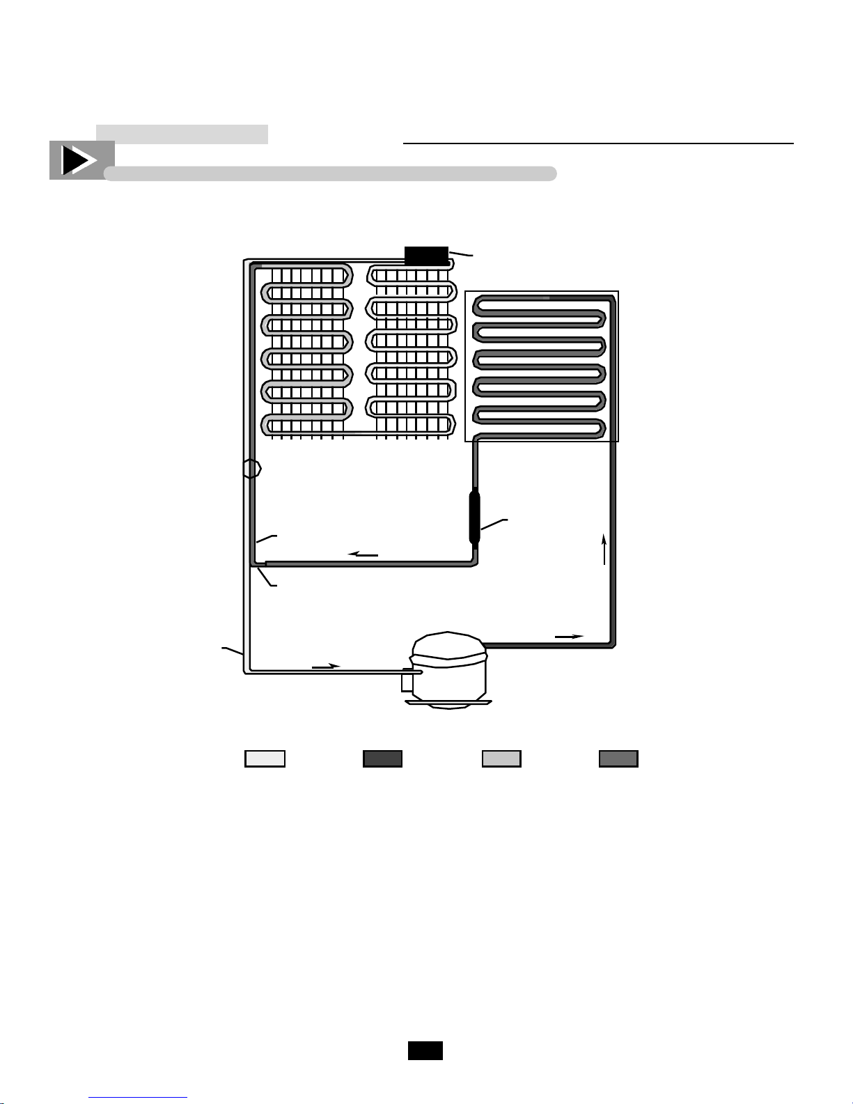
BASIC REFRIGERATION
THE CAPILLARY TUBE SYSTEM
Suction
Line
Capillary
Tube
Heat
Exchanger
Evaporator
Accumulator
Condenser
FilterDrie
Motor Compressor
LOW PRESSURE
GAS
Starting at the Capillary Tube, refrigerant flows into
the evaporator and changes from a liquid to a gas. As it
absorbs heat, after leaving the evaporator, it flows
through the accumulator. The accumulator is a part
that is designed like a reservoir to allow any refrigerant,
that has not changed from a liquid to a gas, space to do
so before returning to the compressor. After flowing
through the accumulator, refrigerant flows through the
s u c t i o n line as a low pressure gas into the compressor.
The compressor pumps the refrigerant from a low pressure gas to a high pressure gas and forces it into the
condenser. In the condenser with a fan circulating air
over it the refrigerant condenses from high pressure
HIGH PRESSURE
GAS
LOW PRESSURE
LIQUID
HIGH PRESSURE
LIQUID
gas to high pressure liquid. After leaving the condenser
refrigerant flow through the drier which is designed to
remove any particles or moisture in the system.
Refrigerant then flows through the liquid line into the
capillary tube. The capillary tube is designed to allow
a certain amount of refrigerant to flow through it to
keep the evaporator evenly flooded. The capillary tube
is taped to the suction line to cool the liquid to allow
the best heat transfer. When the refrigerant enters the
evaporator as a liquid, warm air from inside the cabinet
is circulated through the evaporator coil and the heat
from the air is then absorbed in the refrigerant.
Thermostat
Senses evaporator
temperature
@40°F cuts in starts compressor
@18°F cuts out shuts compressor
off
Evaporator
As air is pushed
through the
evaporator by the
fan motors liquid
refrigerant absorbs
heat through the
walls of the
evaporator coils and
vaporizes - thus
becoming a low
pressure gas.
®
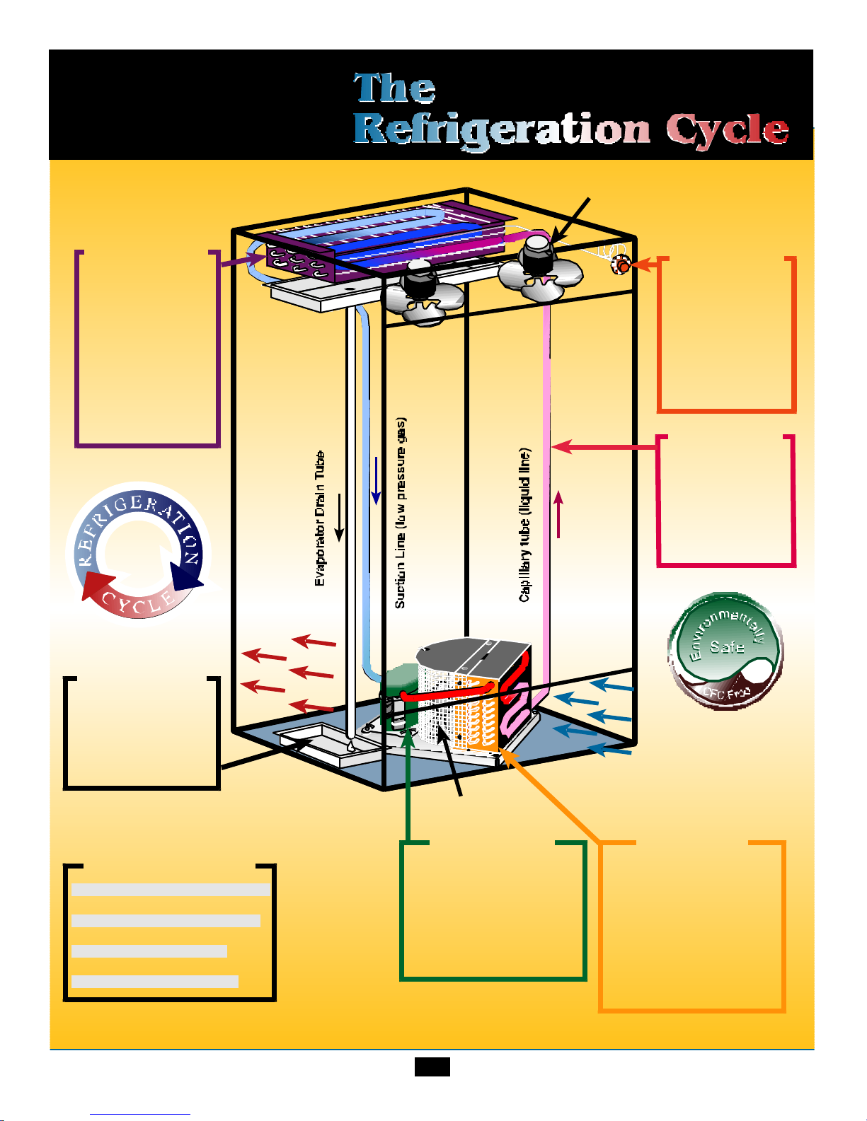
24
®
Evaporator
Fan Motor
Condensate
Pan
The resulting warm air
from the condensor
blows over the
condensate pan and
evaporates the water.
Hot air out
Cool air in
Capillary
Tube
Meters the amount
of liquid refrigerant
into the evaporator
where it absorbs
heat.
Color Chart
Dark Blue = Low pressure liquid
Light Blue = Low pressure gas
Red = High pressure gas
Pink = High pressure liquid
Compressor
Fan Motor
Compressor
Combines heat absorbed
in the evaporator coils with
heat of compression from
the piston stroke then
pushes high pressure gas
(vapor) on into the
condenser.
Condenser
High pressure gas is
condensed into a high
pressure liquid when the
heat is removed. By pulling
air in the front of the
condenser by means of the
fan motor. The air will be
used to evaporate the drain
pan water.
25
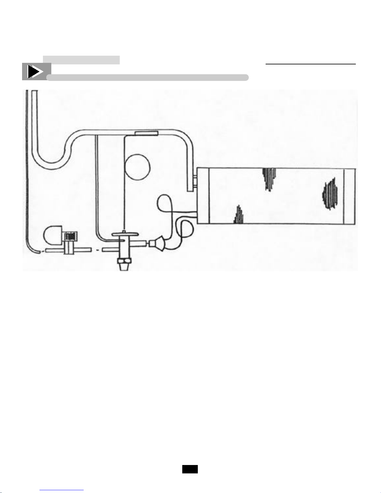
TRUE’S REMOTE SYSTEM - HOW IT WORKS
Liquid and Suction
Tubing
‘P’ Trap
TXV Bulb
Suction Line
External
Equalizer
Refrigeration Schematic Diagram
TXV
Liquid Line
Solenoid
Distributor
with Nozzle
The suction line will exit the evaporator coil as usual
for self-contained models, except it shall include an
Oil “P” trap. This is used to trap oil in low velocity
suction gases at a point just prior to a vertical rise.
Whether the compressor is to be located above or
below the evaporator, (True does not have control
over this), the suction will always have a “P” trap in
case the compressor is installed overhead.
The liquid line shall enter the cabinet and go directly to the liquid line solenoid, this is a normally
closed refrigerant valve which will be energized and
wired in series with the thermostat. When the thermostat is closed (requires refrigeration) the solenoid
will be energized to open, allowing refrigerant to
pass to the “thermal expansion valve” (TXV). The
TXV allows refrigerant through to the evaporator
coil. If the evaporator has more than one circuit, a
Feeder
Tubes
Evaporator
Coil
distributor is used which evenly distributes refrigerant to each circuit. The TXV is made to open and
close by its sensing bulb which senses suction line
temperature on the other side of the evaporator. The
sensing bulb has the same refrigerant that is used in
the refrigeration system. When hot air passes over
the evaporator coil and warms the refrigerant, the
sensing bulb senses the warm condition and pushes
the sensing valve open. When too much refrigerant
flows into the evaporator, the sensing bulbs refrigerant cools and contracts allowing the diaphragm to
ease away the needle valve, thus closing the valve.
The external equalizer is another sensing element
which helps the sensing bulb to more accurately feed
refrigerant. The external equalizer line must be
down-stream of the TXV bulb. The TXV bulb
should be insulated with corktape.
CFC & REFRIGERATION BASICS
26
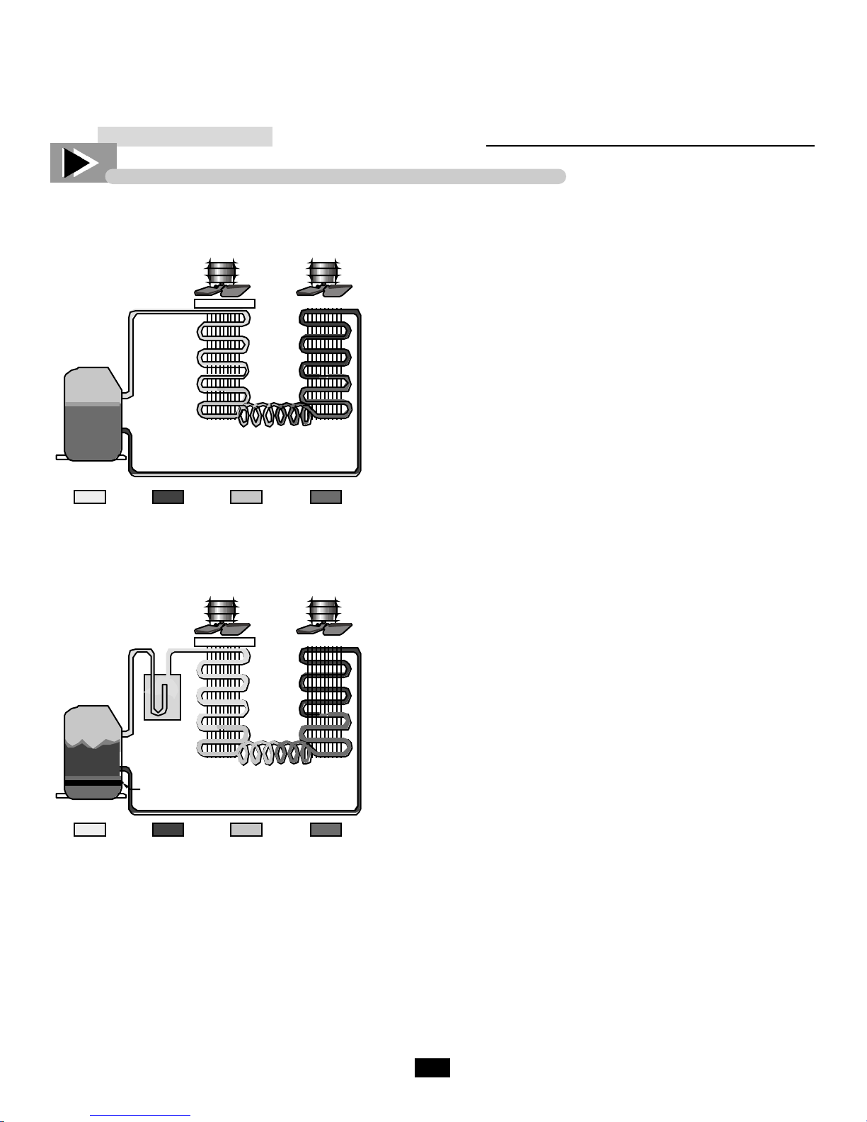
BASIC REFRIGERATION
Control of Liquid Refrigerant Floodback To The Compressor During Operation
Compressor
LOW PRESSURE
GAS
Compressor
HIGH PRESSURE
GAS
Accumulator
Crankcase
Heater
Fan Fan
Filter
Evaporator Condenser
Expansion Device
LOW PRESSURE
LIQUID
Fan Fan
Filter
Evaporator Condenser
Expansion Device
HIGH PRESSURE
LIQUID
Liquid floodback during operation can be caused by fan
failure, or dirty clogged filters that can reduce the heat
transfer rate to such a point that the liquid refrigerant
floods through, instead of vaporizing. When this situation
occurs, liquid refrigerant may enter the compressor under
conditions which result in separation of the oil and refrigerant. This separation may result in an accumulation of the
refrigerant under the oil. Thus, when the compressor is
started, the first liquid to be pumped to the bearings will
probably be refrigerant, not oil. Even if this oil-refrigerant
separation does not occur, the large amount of liquid refrigerant in the crankcase will instantly vaporize and boil away
the oil charge when the compressor starts. Thereby leaving
the compressor oil-starved for many seconds.
Liquid floodback can be prevented by the application of a
properly designed and sized suction line accumulator.
Using a totally new concept, Tecumseh engineers have
designed a suction line accumulator available in eight basic
sizes covering a full range of system applications and
refrigerant. When properly selected based upon system
c h a rge, a Tecumseh suction line accumulator will improve
compressor reliability and endurance by preventing damaging liquid refrigerant floodback.
LOW PRESSURE
GAS
HIGH PRESSURE
GAS
LOW PRESSURE
LIQUID
HIGH PRESSURE
LIQUID REFRIGERANT ACCUMULATION IN THE COMPRESSOR CAN ALSO BE CAUSED BY
LIQUID MIGRATION TOTHE COMPRESSOR DURING PERIODS OF SHUTDOWN. THIS CONDITION CAN BE CONTROLLED BY THE APPLICATION OF A CRANKCASE HEATER. A SUCTION
LINE ACCUMULATOR DOES NOTHING TO PREVENT LIQUID MIGRATION AND ACRANKCASE
HEATER DOES NOTHING TO PREVENT LIQUID FLOODBACK. EACH WITHOUT THE OTHER
IS HALF A JOB - BOTH TOGETHER PROVIDE BALANCED COMPRESSOR PROTECTION.
LIQUID

Notes

28
Using the following instructions you will be able to make cabinet
exterior repairs along with other general cabinet repairs.
GENERAL CABINET
MAINTENANCE
AND REPAIRS
29
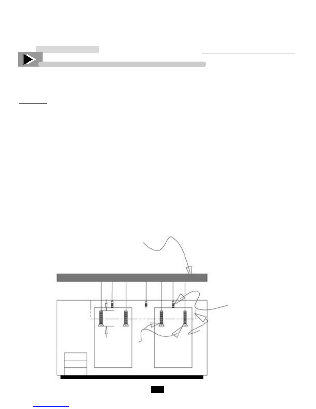
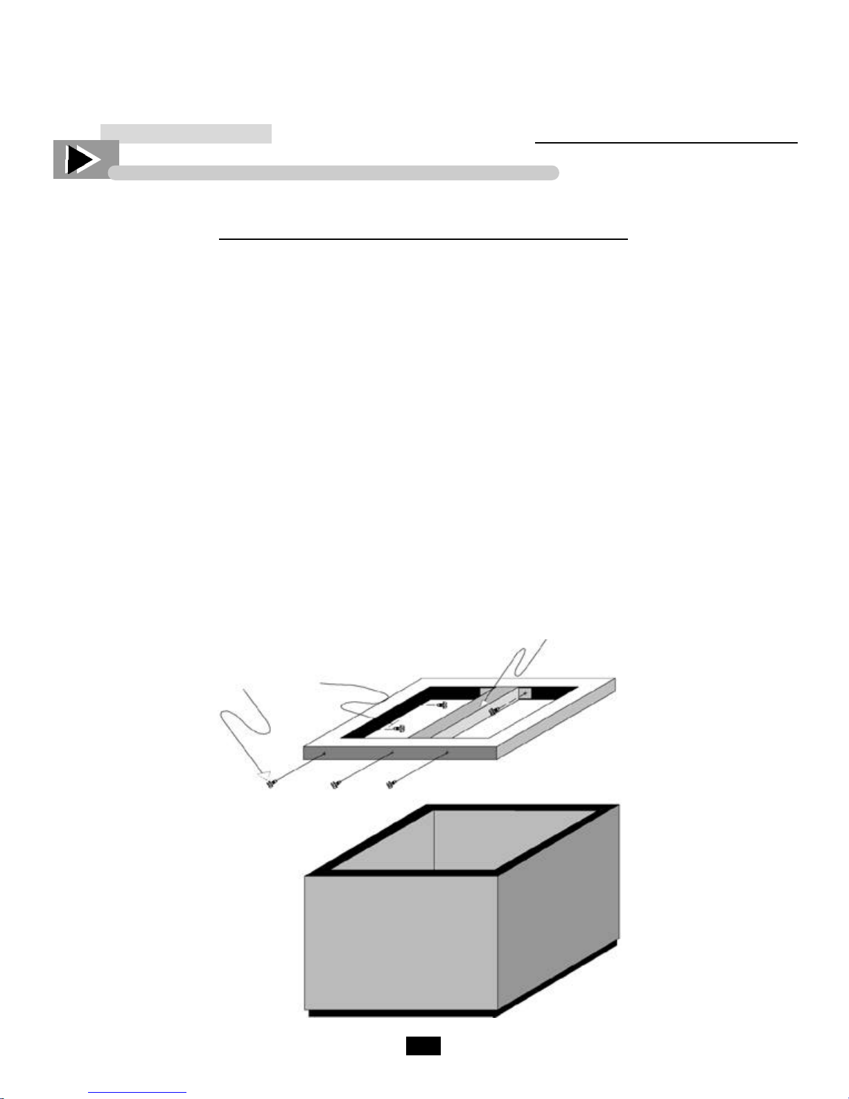
TOP REMOVAL FOR TBB & TDD UNITS
TOP REMOVAL FOR TBB & TDD UNITS
Disconnect the power to the unit.
Locate and remove screws on the inside of the cabinet going through the evaporator housing and into the bottom of the counter top.
Locate and remove the screws securing the line set cover to the top located to the left of the evaporator housing.
Remove the two screws inside the door jamb going through the jamb into the bottom of the top. There will be
two screws in each door on multiple door units.
Cut the silicone seal that runs along both ends and along the back of the unit. Silicone seal is wrapped around
the front wall of multiple door units.
To remove top lift front up approximately 2-3 inches and push backward to unlock lip in back of top.
To reinstall top, carefully align the groove in the back with lip on cooler base. Slide forward, reinstall all
screws and re-silicone around cabinet edge.
3”
Top Screws
Top
Evaporator
Housing Screws
Evaporator Housing
30
TOP REMOVALFOR TD & T-GC UNITS
TOP REMOVAL FOR TD & T-GC UNITS
1. Turn unit off and remove lids.
2. Remove screws along back of cabinet top.
3. Remove screws on each side, going through lid slide rails, inside cooler.
4. Remove screws along front of top under inside ledge, also remove the two screws holding center trunion
on units with more than one door.
5. Lift top to approximately 45 degrees while pushing top forward at same time. Top will lift off lip in front.
T-50-GC has heater wire looped through center trunion. Please becareful when removing top. Before
reinstalling, inspect heater wire to make sure it is not damaged.
6. To reinstall top, while holding top at 45 degree angle hook top on lip at front of cabinet and lay down while
pushing backwards on top, when laid completely down press firmly on top to provide a good seal.
7. Reinstall all screws along inside of cabinet and along back of top on outside of cabinet.
8. Reinstall doors and turn unit on.
Lid
Trunion
Top Screws
 Loading...