

Page 1
Safe Operation Practices • Set-Up • Operation • Maintenance • Service • Troubleshooting • Warranty
Op e r a t O r ’s Ma n u a l
3-in-1 Battery Mower — TB E25
WARNING
READ AND FOLLOW ALL SAFETY RULES AND INSTRUCTIONS IN THIS MANUAL
BEFORE ATTEMPTING TO OPERATE THIS MACHINE.
FAILURE TO COMPLY WITH THESE INSTRUCTIONS MAY RESULT IN PERSONAL INJURY.
TROY-BILT LLC, P.O. BOX 361131 CLEVELAND, OHIO 44136-0019
Form No. 769-06399
(October 25, 2010)
Page 2
To The Owner
Thank You
Thank you for purchasing a Troy-Bilt Electric Mower. It was
carefully engineered to provide excellent performance when
properly operated and maintained.
Please read this entire manual prior to operating the equipment.
It instructs you how to safely and easily set up, operate and
maintain your machine. Please be sure that you, and any other
persons who will operate the machine, carefully follow the
recommended safety practices at all times. Failure to do so could
result in personal injury or property damage.
All information in this manual is relative to the most recent
product information available at the time of printing. Review
this manual frequently to familiarize yourself with the machine,
its features and operation. Please be aware that this Operator’s
Manual may cover a range of product specifications for various
models. Characteristics and features discussed and/or illustrated
in this manual may not be applicable to all models. Troy-Bilt LLC
reserves the right to change product specifications, designs and
equipment without notice and without incurring obligation.
Table of Contents
Safe Operation Practices ........................................ 3
Assembly & Set-Up .................................................. 8
Controls ...................................................................12
Operation ................................................................13
1
If you have any problems or questions concerning the machine,
phone a authorized Troy-Bilt service dealer or contact us directly.
Troy-Bilt’s Customer Support telephone numbers, website
address and mailing address can be found on this page. We want
to ensure your complete satisfaction at all times.
Throughout this manual, all references to right and left side of the
machine are observed from the operating position
Maintenance & Adjustment..................................15
Service .....................................................................17
Troubleshooting .....................................................19
Warranty ..................................................Back Cover
Record Product Information
Before setting up and operating your new equipment, please
locate the model plate on the equipment and record the
information in the provided area to the right. You can locate the
model plate by standing at the operator’s position and looking
down at the rear of the deck. This information will be necessary,
should you seek technical support via our web site, Customer
Support Department, or with a local authorized service dealer.
MO d e l nu M b e r
se r i a l nu M b e r
Customer Support
Please do NOT return the machine to the retailer or dealer without first contacting our Customer Support Department.
If you have difficulty assembling this product or have any questions regarding the controls, operation, or maintenance of
this machine, you can seek help from the experts. Choose from the options below:
Visit us on the web at www.troybilt.com◊
Call a Customer Support Representative at (800) 828-5500 or (330) 558-7220◊
Write us at Troy-Bilt LLC • P.O. Box 361131 • Cleveland, OH • 44136-0019◊
2
Page 3

Important Safe Operation Practices
WARNING: This symbol points out important safety instructions which, if not followed,
could endanger the personal safety and/or property of yourself and others. Read and follow
all instructions in this manual before attempting to operate this machine. Failure to comply
with these instructions may result in personal injury.
When you see this symbol. HEED ITS WARNING!
DANGER: This machine was built to be operated according to the rules for safe operation in
this manual. As with any type of power equipment, carelessness or error on the part of the
operator can result in serious injury. This machine is capable of amputating hands and feet
and throwing objects. Failure to observe the following safety instructions could result in
serious injury or death.
2
Children
Tragic accidents can occur if operator is not alert to presence
of children. Children are often attracted to mower and mowing
activity. They do not understand the dangers. Never assume that
children will remain where you last saw them.
Keep children out of the mowing area and under watchful 1.
care of a responsible adult other than the operator.
Be alert and turn mower off if a child enters the area.2.
Before and while moving backwards, look behind and 3.
down for small children.
Use extreme care when approaching blind corners, 4.
doorways, shrubs, trees, or other objects that may obscure
your vision of a child who may run into the mower.
Never allow children under 14 years old to operate a power 5.
mower. Children 14 years old and over should read and
understand operation instructions and safety rules in this
manual and should be trained and supervised by a parent.
Operation
General Operation:
Read this operator’s manual carefully in its entirety before 1.
attempting to assemble this machine. Read, understand,
and follow all instructions on the machine and in the
manual(s) before operation. Be completely familiar with
the controls and the proper use of this machine before
operating it. Keep this manual in a safe place for future and
regular reference and for ordering replacement parts.
This machine is a precision piece of power equipment, 2.
not a plaything. Therefore, exercise extreme caution at all
times. Your unit has been designed to perform one job: to
mow grass. Do not use it for any other purpose.
Don’t force lawn mower — it will do the job better and 3.
safer at the rate for which it was designed.
Never allow children under 14 years old to operate this 4.
machine. Children 14 years old and over should read and
understand the instructions in this manual and should
be trained and supervised by a parent. Only responsible
individuals who are familiar with these rules of safe
operation should be allowed to use this machine.
Thoroughly inspect the area where the equipment is to be 5.
used. Remove all stones, sticks, wire, bones, toys and other
foreign objects which could be tripped over or picked
up and thrown by the blade. Thrown objects can cause
serious personal injury. Plan your mowing pattern to avoid
discharge of material toward roads, sidewalks, bystanders
and the like. Also, avoid discharging material against a wall
or obstruction which may cause discharged material to
ricochet back toward the operator.
To help avoid blade contact or a thrown object injury, 6.
stay in operator zone behind handles and keep children,
bystanders and pets at least 75 feet from mower while it is
in operation. Stop machine if anyone enters area.
Always wear safety glasses or safety goggles during 7.
operation and while performing an adjustment or repair
to protect your eyes. Thrown objects which ricochet can
cause serious injury to the eyes.
Wear sturdy, rough-soled work shoes and close-fitting 8.
slacks and shirts. Shirts and pants that cover the arms
and legs and steel-toed shoes are recommended. Never
operate this machine in bare feet, sandals, slippery or light
weight (e.g. canvas) shoes.
Do not put hands or feet near rotating parts or under 9.
cutting deck. Contact with blade can amputate hands and
feet.
A missing or damaged discharge cover can cause blade 10.
contact or thrown object injuries.
Many injuries occur as a result of the mower being pulled 11.
over the foot during a fall caused by slipping or tripping.
Do not hold on to the mower if you are falling; release the
handle immediately.
3
Page 4

Never pull the mower back toward you while you are 12.
walking. If you must back the mower away from a wall or
obstruction first look down and behind to avoid tripping
and then follow these steps:
Step back from mower to fully extend your arms.a.
Be sure you are well balanced with sure footing.b.
Pull the mower back slowly, no more than half way c.
toward you.
Repeat these steps as needed.d.
Do not operate the mower while under the influence of 13.
alcohol or drugs.
Stay alert — Watch what you are doing. Use common 14.
sense. Do not operate lawn mower when you are tired.
The motor/blade control handle is a safety device. Never 15.
attempt to bypass its operation. Doing so makes the
safety device inoperative and may result in personal injury
through contact with the rotating blade. The motor/blade
control handle must operate easily in both directions and
automatically return to the disengaged position when
released.
Do not charge the mower in rain, or in wet conditions.16.
Never operate the mower in rain or wet grass. Always 17.
be sure of your footing. A slip and fall can cause serious
personal injury. If you feel you are losing your footing,
release the motor/blade control handle immediately and
the blade will stop rotating within three seconds.
Mow only in daylight or good artificial light. Walk, never 18.
run.
Stop the blade when crossing gravel drives, walks or roads.19.
If the equipment should start to vibrate abnormally, stop 20.
the motor and check immediately for the cause. Vibration
is generally a warning of trouble.
Shut the motor off and wait until the blade comes to 21.
a complete stop before removing the grass catcher or
unclogging the chute. The cutting blade continues to
rotate for a few seconds after the motor is shut off. Never
place any part of the body in the blade area until you are
sure the blade has stopped rotating.
Never operate mower without proper trail shield, 22.
discharge cover, grass catcher, motor/blade control handle
or other safety protective devices in place and working.
Never operate mower with damaged safety devices. Failure
to do so, can result in personal injury.
Only use parts and accessories made for this machine by 23.
manufacturer. Failure to do so can result in personal injury.
If situations occur which are not covered in this manual, use 24.
care and good judgment. Telephone Customer Support for
the name of your nearest dealer.
Slope Operation:
Slopes are a major factor related to slip and fall accidents which
can result in severe injury. Operation on slopes requires extra
caution. If you feel uneasy on a slope, do not mow it. For your
safety, use the slope gauge included as part of this manual to
measure slopes before operating this unit on a sloped or hilly
area. If the slope is greater than 15 degrees, do not mow it.
Do:
Mow across the face of slopes; never up and down. Exercise 1.
extreme caution when changing direction on slopes.
Watch for holes, ruts, rocks, hidden objects, or bumps 2.
which can cause you to slip or trip. Tall grass can hide
obstacles.
Always be sure of your footing. A slip and fall can 3.
cause serious personal injury. If you feel you are losing
your balance, release the motor/blade control handle
immediately, and the blade will stop rotating within three
(3) seconds.
Do Not:
Do not mow near drop-offs, ditches or embankments, you 1.
could lose your footing or balance.
Do not mow slopes greater than 15 degrees as shown on 2.
the slope gauge.
Do not mow on wet grass. Unstable footing could cause 3.
slipping.
Service
If the mower’s built-in overload protection switch 1.
frequently trips, contact your nearest authorized service
dealer for repair.
Remove key and store idle lawn mower indoors when not 2.
in use. Allow motor to cool before storing in any inclosure.
Lawn mower should be stored indoors in a dry, high, or
locked-up place, out of reach of children.
When servicing use only identical replacement parts 3.
listed in this manual. “Use of parts which do not meet the
original equipment specifications may lead to improper
performance and compromise safety!”
Before cleaning, repairing, or inspecting, make certain the 4.
blade and all moving parts have stopped. Remove the key
to prevent accidental starting.
Remove key before servicing, cleaning, or removing 5.
material from the lawn mower.
Follow instructions for lubricating and changing 6.
accessories.
Keep handles dry, clean and free from oil and grease.7.
To reduce a fire hazard, keep the motor cover free of grass, 8.
leaves and debris build-up.
Check the blade and motor mounting bolts at frequent 9.
intervals for proper tightness. Also, visually inspect blade
for damage (e.g., bent, cracked, and worn). Replace blade
with the original equipment manufacturer’s (OEM) blade
only, listed in this manual.
4 se c t i O n 2— iM p O r t a n t sa f e Op e r a t i O n pr a c t i c e s
Page 5

Maintain your mower with care — Keep mower blade sharp 10.
and clean for best and safest performance. Mower blades
are sharp and can cut, wrap the blade or wear gloves and
use extra caution when servicing them.
Keep all nuts, bolts, and screws tight to be sure the 11.
equipment is in safe working condition.
Never tamper with safety devices. Check their proper 12.
operation regularly.
Never attempt to make wheel or cutting height 13.
adjustments while the motor is running.
After striking a foreign object, stop the motor, remove the 14.
key, and thoroughly inspect the mower for any damage.
Repair the damage before operating the mower.
Grass catcher components, discharge cover, and trail shield 15.
are subject to wear and damage which could expose
moving parts or allow objects to be thrown. For safety
protection, frequently check components and replace
immediately with original equipment manufacturer’s
(OEM) parts only, listed in this manual.
According to the Consumer Products Safety Commission 16.
(CPSC) and the U.S. Environmental Protection Agency (EPA),
this product has an Average Useful Life of seven (7) years, or
140 hours of operation. At the end of the Average Useful Life
have the unit inspected annually by an authorized service
dealer to ensure that all mechanical and safety systems are
working properly and not worn excessively. Failure to do so
can result in accidents, injuries or death.
Do not dispose of the battery(ies) in a fire. The cell may 17.
explode. Check with local codes for possible special
disposal instructions.
Do not open or mutilate the battery(ies). Released 18.
electrolyte is corrosive and may cause damage to the eyes
or skin. It may be toxic if swallowed.
Exercise care in handling batteries in order not to short the 19.
battery with conducting materials such as rings, bracelets,
and keys. The battery or conductor may overheat and
cause burns.
5se c t i O n 2 — iM p O r t a n t sa f e Op e r a t i O n pr a c t i c e s
Page 6
Safety Symbols
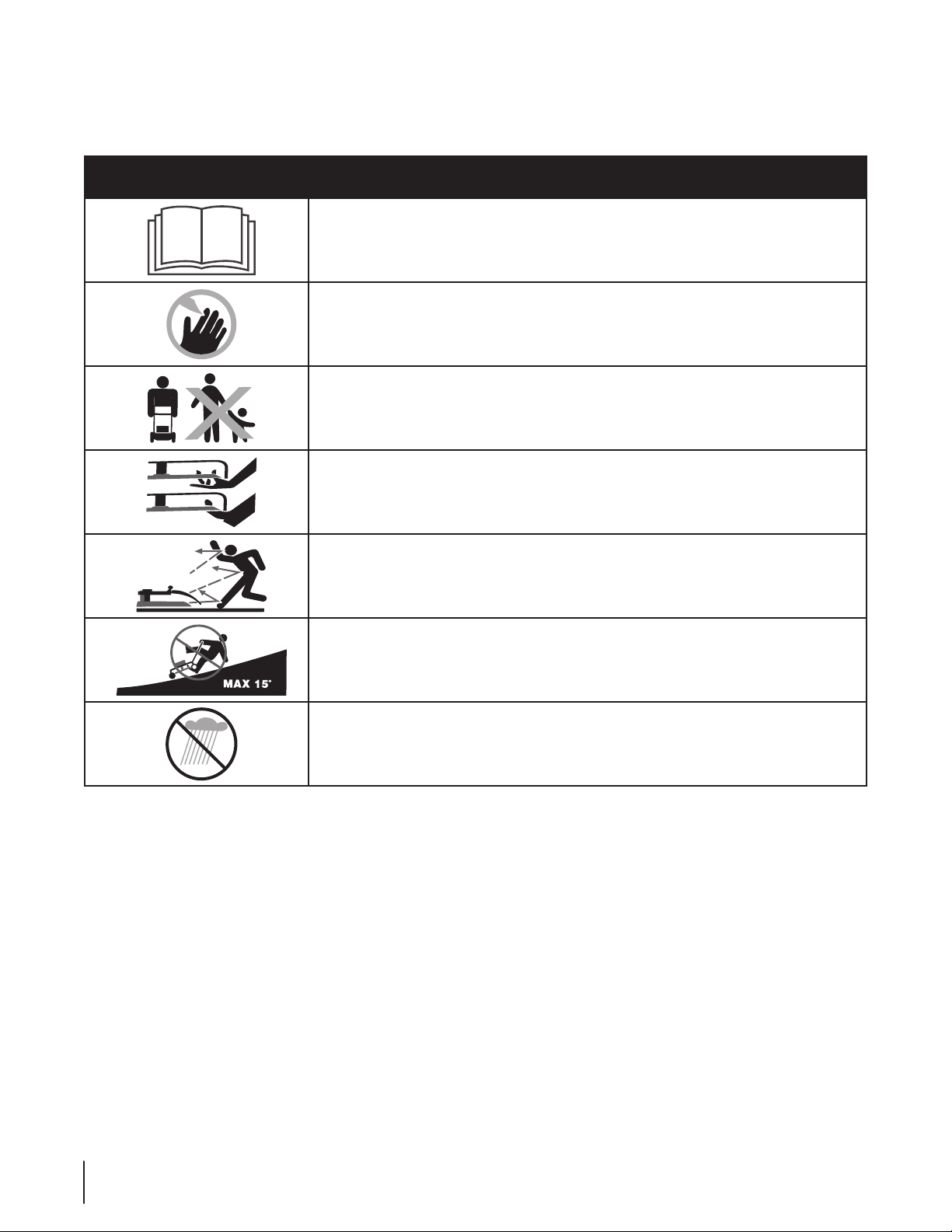
This page depicts and describes safety symbols that may appear on this product. Read, understand, and follow all instructions on the
machine before attempting to assemble and operate.
Symbol Description
READ THE OPERATOR’S MANUAL(S)
Read, understand, and follow all instructions in the manual(s) before attempting to
assemble and operate
DANGER — ROTATING BLADES
To reduce the risk of injury, keep hands and feet away. Do not operate unless discharge cover
or grass catcher is in its proper place. If damaged, replace immediately.
DANGER — BYSTANDERS
Do not mow when children or others are around.
DANGER — HAND/ FOOT CUT
Keep hands and feet away from rotating parts.
DANGER — THROWN DEBRIS
Remove objects that can be thrown by the blade in any direction. Wear safety glasses.
DANGER — SLOPES
Use extra caution on slopes. Do not mow slopes greater than 15°.
WARNING— ELECTRICAL SHOCK
Do not operate the mower in the rain.
6 se c t i O n 2— iM p O r t a n t sa f e Op e r a t i O n pr a c t i c e s
Page 7
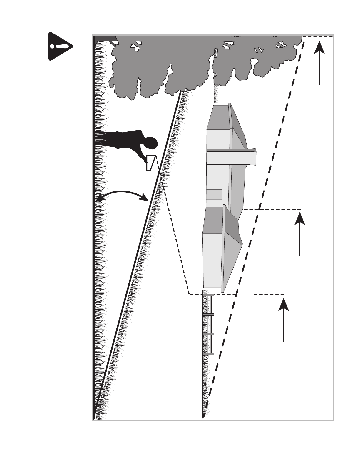
Sight and hold this level with a vertical tree...
or a corner of a building...
or a fence post
Fold along dotted line (represents a 15° slope)
15°
Use this page as a guide to determine slopes where you may not operate safely.
WARNING: Do not operate your lawn mower on such slopes. Do not mow on inclines with a slope in excess of 15 degrees
(a rise of approximately 2-1/2 feet every 10 feet). A riding mower could overturn and cause serious injury. Operate riding
mowers up and down slopes, never across the face of slopes. Operate walk-behind mowers across the face of slopes, never
up and down slopes.
7se c t i O n 2 — iM p O r t a n t sa f e Op e r a t i O n pr a c t i c e s
Page 8
Top View
1
2
3
Assembly & Set-Up
Contents of Carton
One Battery Mower• One Side Discharge Chute• Two Cord Guides•
One Operator’s Manual• Two Toggle Clamps• One Battery•
One Charger• One Grass Bag•
3
NOTE: All references to the left and right side of the mower are
from the operator’s position behind the mower.
Unpacking the Unit
Cut the corners of the carton and lay the sides flat on the 1.
ground. Remove all packing inserts.
Move the mower out of the carton.2.
Make certain the carton has been completely emptied 3.
before discarding it.
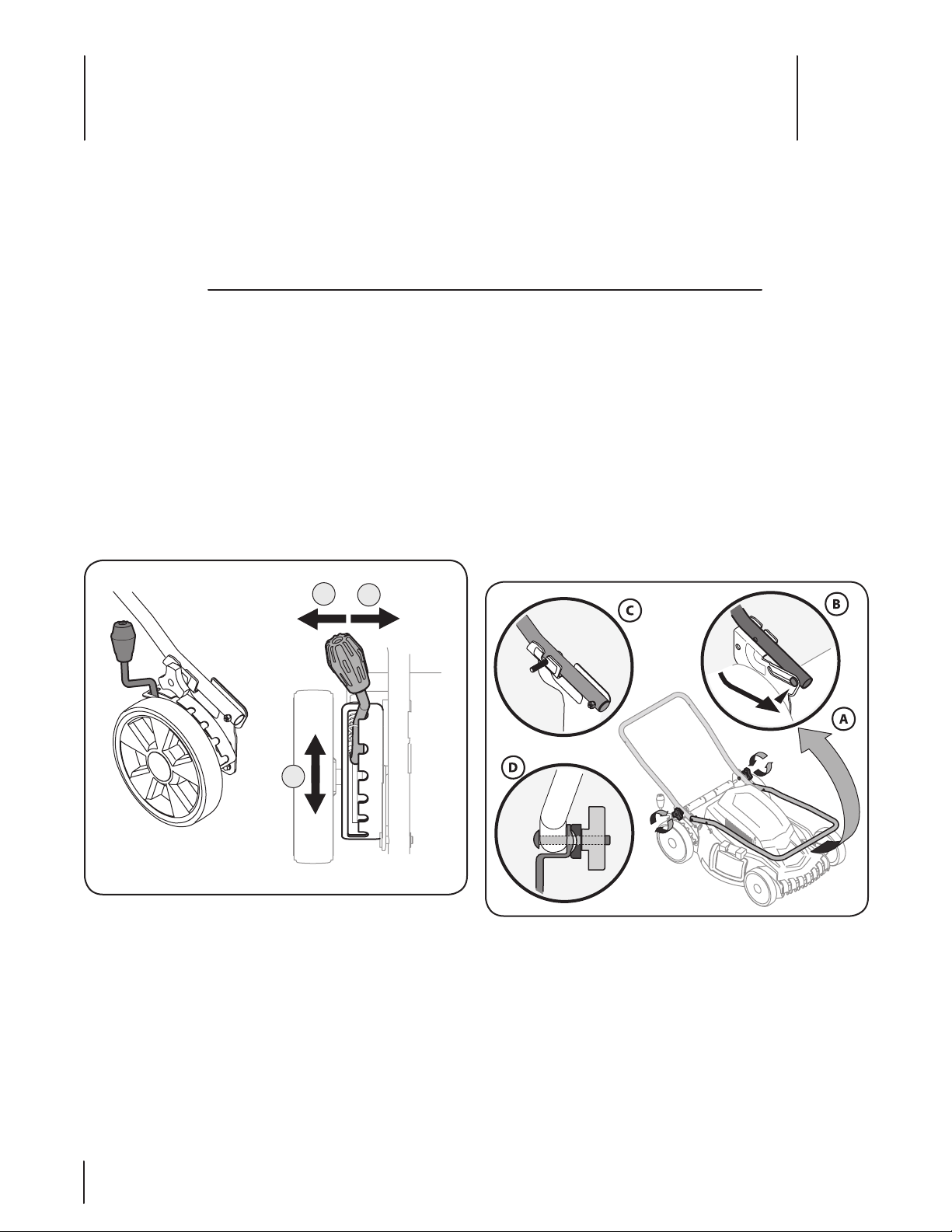
Cutting Height Adjustment
The cutting height adjustment lever is located above the rear
right wheel. See Fig. 3-1.
Handle Assembly
Raise the cutting height adjustment to the highest setting. 1.
See Fig. 3-1.
To assemble the lower handle:2.
Pivot the lower handle backward. See Fig. 3-2A.a.
Place the bolts in the lower handle in the slots of the b.
handle bracket. See Fig. 3-2B.
Make sure the bolts in the lower handle are fully c.
positioned in the slots of the handle bracket. See
Fig. 3-2C.
NOTE: Make sure motor cord is clear of wing knobs before
tightening.
Tighten the lower handle wing knobs. See Fig. 3-2D.d.
Figure 3-1
Pull the lever out and away from the mower.1.
Move the lever forward or back for desired cutting height.2.
Release lever towards mower deck.3.
Figure 3-2
8
Page 9
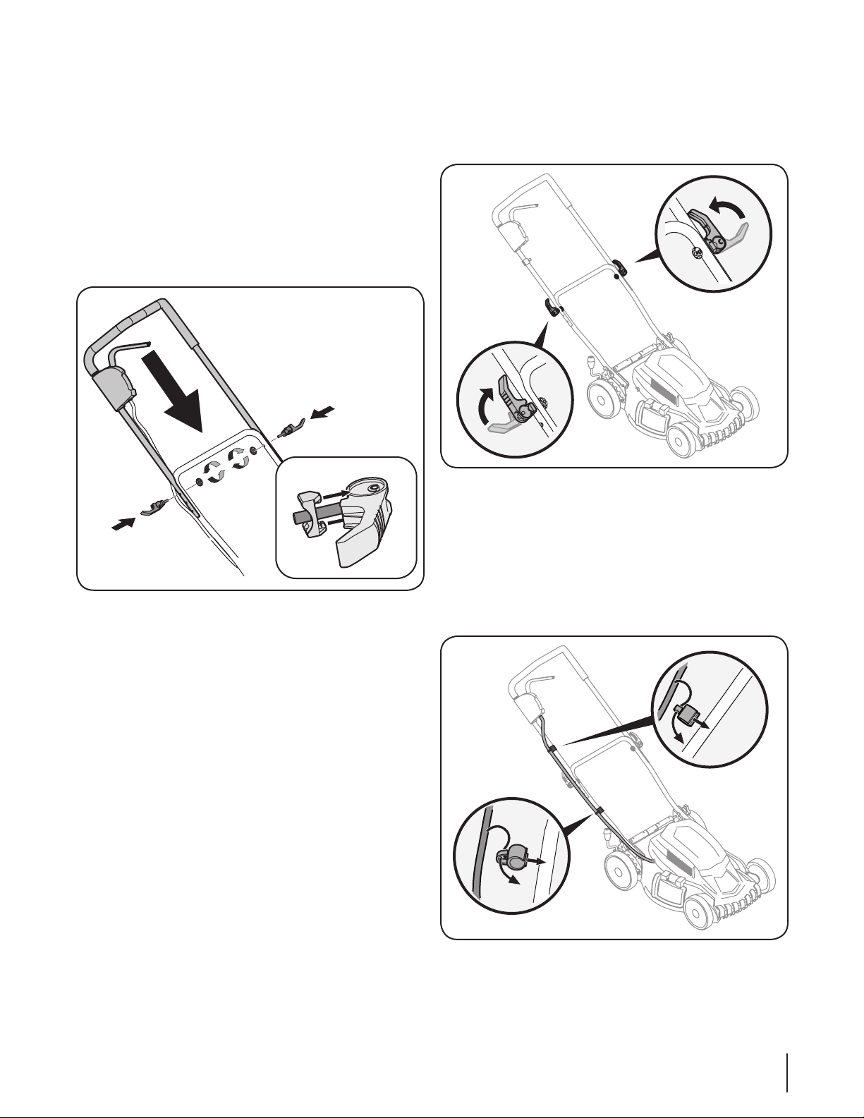
Place the upper handle onto the lower handle, keeping the 5.
motor cord over the handles. See Fig. 3-3.
For the lowest setting, line up the top holes of the a.
upper handle with the holes on the lower handle.
For the medium setting, line up the middle holes b.
of the upper handle with the holes on the lower
handle.
For the highest setting, line up the bottom holes c.
of the upper handle with the holes on the lower
handle.
NOTE: Make certain the clips on the clamp retainers are
inside the grooves of the clamp seats. See Fig. 3-3 inset.
Tighten the clamps. See Fig. 3-4.5.
NOTE: Leave space between clamp and clamp seat. If
clamp will not tighten, loosen wing knob half turn. If clamp
is not firmly seated when engaged, tighten wing knob half
turn until clamp is firmly seated when engaged.
Figure 3-4
Figure 3-3
Insert toggle clamps packed separately with the mower 4.
into the holes for the selected height. See Fig. 3-3.
Cord Guide
Make sure the cord between the motor/blade control lever
and the mower sits in the cord holders on the upper and lower
handles.
Snap one cord guide onto the lower handle and the other 1.
cord guide onto the upper handle. See Fig. 3-5.
Secure the motor cord in the cord guide clamps.2.
Figure 3-5
9se c t i O n 3 — as s e M b l y & se t -up
Page 10
Grass Collection
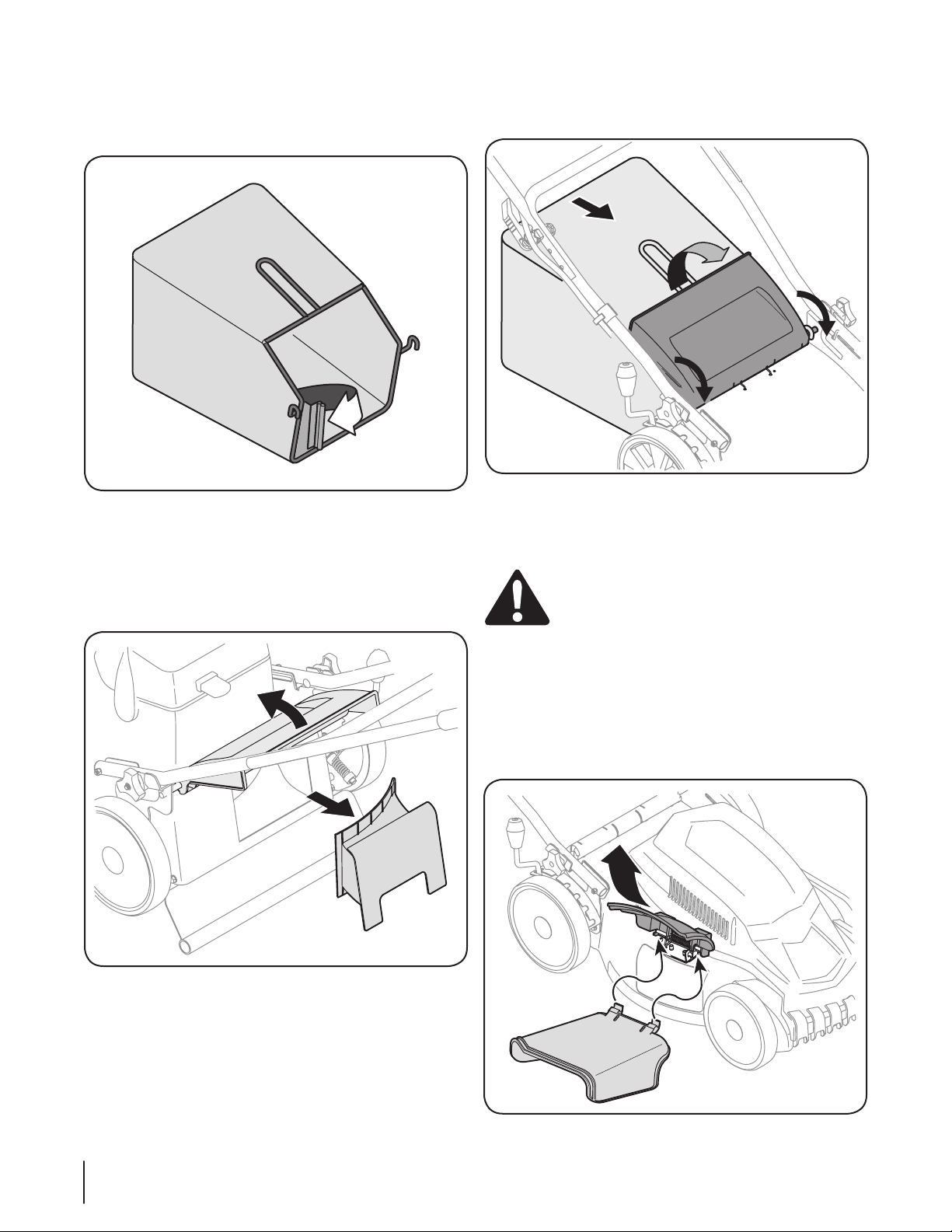
To assemble the grass catcher, secure the plastic channels 1.
of grass bag over frame rods. See Fig. 3-6.
Figure 3-6
Follow steps below to attach grass catcher:2.
Lift rear discharge door.a.
Remove rear mulching baffle. See Fig. 3-7.b.
NOTE: Swing the mulching baffle to the right side of the
mower and then slide out.
Place grass catcher on the pivot rod. Let go of c.
discharge door so that it rests on the grass catcher.
See Fig. 3-8.
Figure 3-8
To remove grass catcher, lift rear discharge door on the mower.
Lift grass catcher up and out, off of the pivot rod. Release rear
discharge door to allow it to close rear opening of mower.
WARNING: Never operate mower unless the hooks
on the grass catcher are firmly seated on the pivot
rod and the rear discharge door rests firmly against
top of the grass catcher.
Figure 3-7
Side Discharge
For side discharge, you will need to have the rear mulching baffle
installed below the rear discharge door.
On the right side of the mower, lift the mulch baffle.1.
Slide the hooks of the side discharge chute under hinge pin 2.
on mulch baffle assembly. See Fig. 3-9.
10 se c t i O n 3 — as s e M b l y & se t -up
Figure 3-9
Page 11
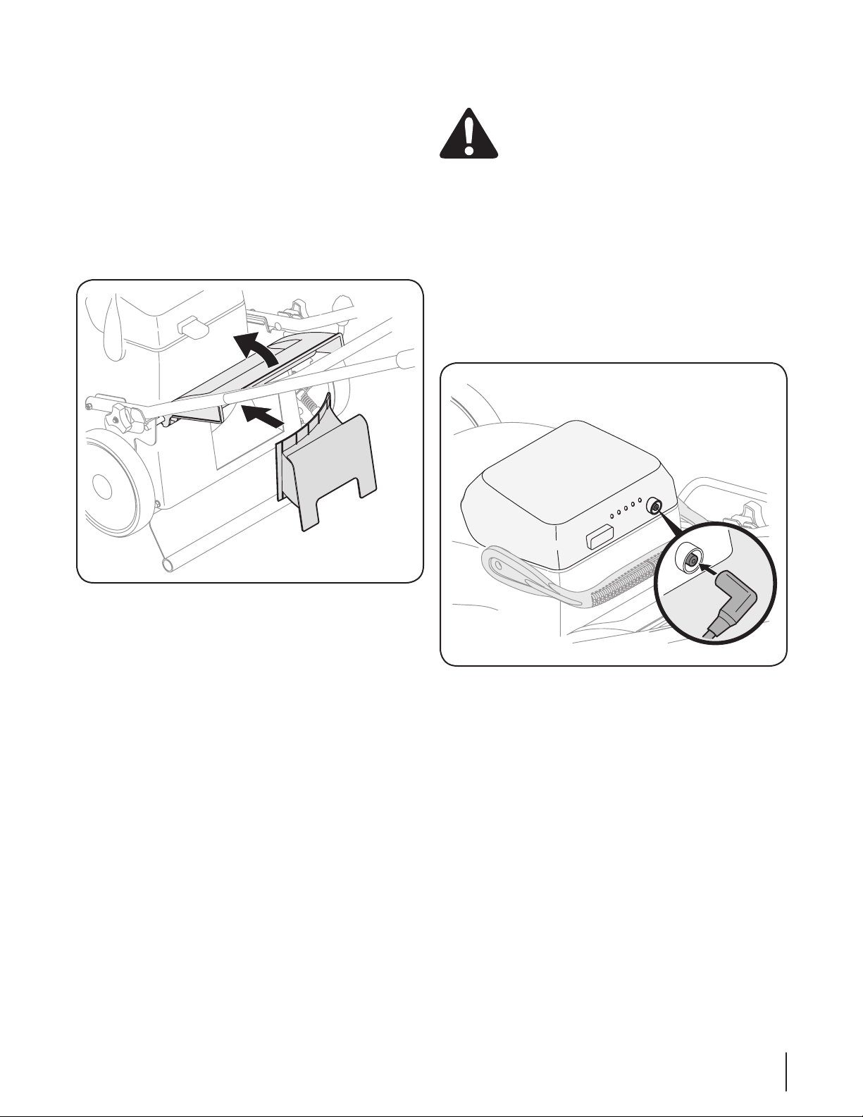
Secure the tabs of the side discharge chute onto the hooks 3.
below the side mulching baffle. See Fig. 3-9.
NOTE: Do not remove side mulch baffle at any time, even
when you are not mulching.
Mulching
To mulch, you will need the rear mulching baffle installed below
the rear discharge door.
If converting to mulching from the grass collection mode:
Remove grass catcher.1.
Install rear mulching baffle. See Fig. 3-10.2.
Charging the Battery
WARNING: The battery contains corrosive fluid
and toxic material - HANDLE WITH CARE. Keep away
from children. Do not puncture, disassemble,
mutilate, or incinerate. Explosive gases could be
vented during charging or discharging. Use in a well
ventilated area, away from sources of ignition.
IMPORTANT: Use only with battery pack 725-05089.
Charge the mower for 14 hours before initial use. Charge
mower indoors in a dry area out of the weather. DO NOT charge
in rain or wet locations.
IMPORTANT: Use only the battery charger provided with this
mower.
Plug the battery charger into the battery first, and then into any
standard 110/120 volt household electrical outlet. See Fig. 3-11
for battery charging location.
Figure 3-10
If converting to mulching from side discharge:
Remove side discharge chute.1.
Make sure the rear mulching baffle is installed. See 2.
Fig. 3-10.
Figure 3-11
NOTE: If an extension cord is required, use one that is at least
wire size 16 AWG. Connect the extension cord to charger before
plugging extension cord into electrical outlet.
NOTE: You may charge the battery with the battery removed
from the mower.
IMPORTANT: Always recharge battery fully. It takes 14 hours to
recharge a completely discharged battery. A flashing light on
the battery charger indicates the battery is less than 80 percent
charged; a solid green light indicates the battery is 80 to 100
percent charged. A full charge will be achieved in less than 14
hours if the batteries were only partially discharged.
NOTE: It is recommended that the mower be charged once every
two months during storage.
IMPORTANT: Always disconnect battery charger (or extension
cord, if used) from the electrical outlet first, then disconnect
battery charger from battery.
NOTE: It is recommended that the mower be charged
immediately after it has been discharged. Storing batteries in a
discharged state could reduce future performance.
11se c t i O n 3 — as s e M b l y & se t -up
Page 12
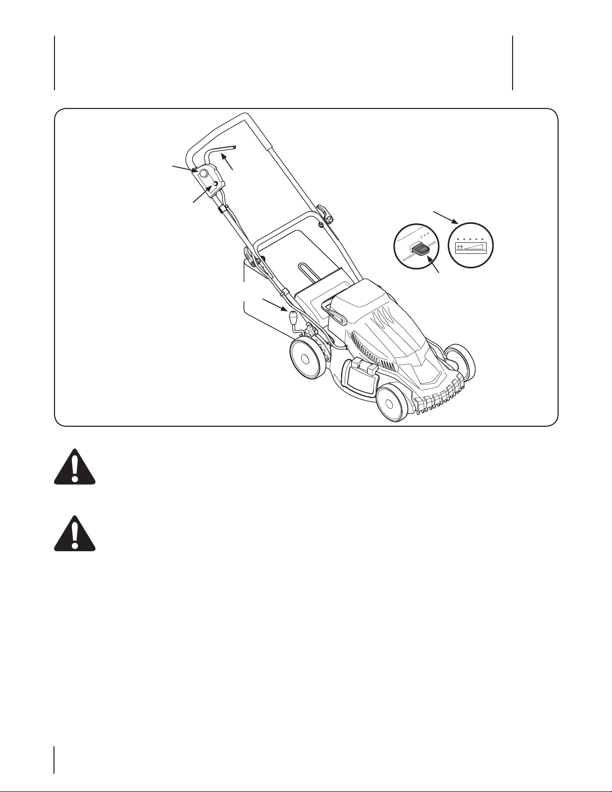
Motor/Blade
Control Lever
Safety Key
Overload Protection
Switch
Cutting Height
Adjustment Lever
Battery Level
Indicator
Starter
Button
Controls and Features
4
Figure 4-1
WARNING: Read, understand, and follow all
instructions and warnings on the machine and in
this manual before operating.
Motor/Blade Control Lever
WARNING: The motor/blade control lever is a
safety device. Never attempt to bypass its
operations.
The motor/blade control lever is located on the upper handle
of the mower. The motor/blade control lever engages and
disengages the motor and blade.
Overload Protection Switch
The mower is equipped with an overload protection switch,
located on the motor/blade control. This overload protection
switch may pop out when too much strain is placed on the
motor. Refer to the Maintenance & Adjustments Section to reset
this switch.
Cutting Height Adjustment Lever
The cutting height adjustment lever is located above the right
rear wheel. To adjust the cutting height, refer to the Assembly
Section.
Starter Button
The starter button is located on the upper handle of the mower.
Engaging the motor/blade control lever with the starter button
pressed will start the mower.
Battery Level Indicator
The battery level indicator is located on the battery. The indicator
shows the condition of the battery and is on when the motor is
on. The indicator lit all the way to the right indicates the battery
is fully charged; as the indicator is lit more toward the left, it
indicates the battery is discharging. See Fig. 4-1 inset.
IMPORTANT: If the far left red light illuminates, the batteries will
need to be recharged before further use. Continued operation
before charging may shorten the life of the batteries.
Safety Key
The safety key must be present and inserted before the motor
can be started.
12
Page 13
Operation
5
Starting Motor and Blade
WARNING: Avoid accidental starting. Make sure
you are in the operating position behind the mower
when using it. To avoid serious injury, the operator
and unit should be in a stable position while
starting.
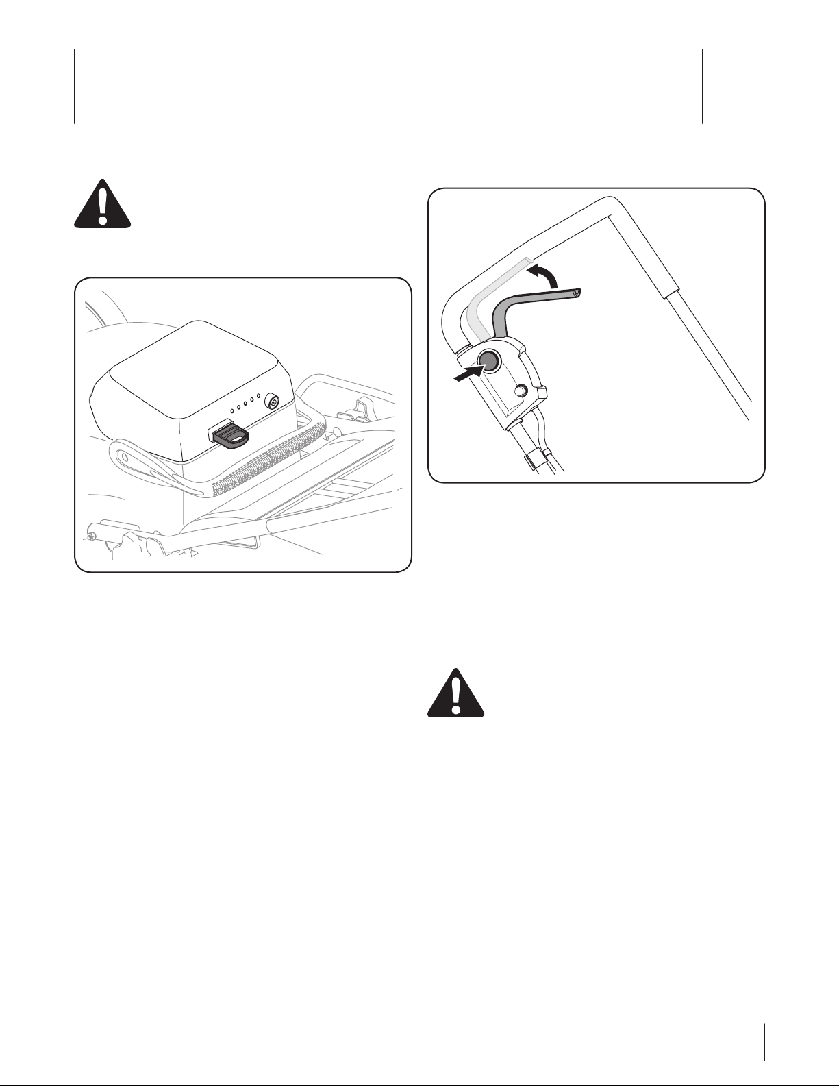
Insert safety key. Refer to Fig. 5-1.1.
Figure 5-1
Stand behind the mower, in the operating position.2.
Press the starter button and hold it in. See Fig. 5-2.3.
NOTE: Starting the mower’s motor also engages the blade.
Figure 5-2
While holding the starter button in, squeeze the motor/4.
blade control lever against the upper handle to start the
motor and engage the blade. See Fig. 5-2.
NOTE: The mower’s motor will NOT start if you fail to
hold the starter button in while pivoting the motor/blade
control handle upward.
Release the starter button.5.
Stopping the Motor
WARNING: The blade continues to rotate for a few
seconds after the motor is shut off. If motor does not
come to a stop when the motor/blade control
handle is released, remove the safety key and
contact an authorized service dealer.
Release the blade/motor control lever to stop the motor 1.
and blade.
Remove the safety key to prevent accidental starting when 2.
equipment is unattended.
Charge the mower.3.
13
Page 14
Using Your Lawn Mower
Unlocked
Locked
Be sure that lawn is clear of stones, sticks, wires, or other objects
which could damage the lawn mower or motor. Such objects
could be accidentally thrown by the mower in any direction and
cause serious personal injury to the operator and others.
WARNING: If you strike a foreign object, stop the
motor, and remove the key. Thoroughly inspect the
mower for any damage, and repair the damage
before restarting and operating the mower.
Excessive vibration of the mower during operation is
an indication of damage. The unit should be
promptly inspected and repaired.
WARNING: The operation of any lawn mower can
result in foreign objects being thrown into the eyes,
which can damage your eyes severely. Always wear
safety glasses while operating the mower, or while
performing any adjustments or repairs on it.
When using the side discharge, the most effective mowing •
pattern is one that allows the clippings to discharge
towards the uncut part of the lawn.
DO NOT use mower in the rain.•
For a healthy lawn, always cut off one-third or less of the •
total length of the grass.
Using as Mulcher
To set up the mulching attachments see the “Assembly & Set-Up”
section. For effective mulching, do not cut wet grass. If the grass
has been allowed to grow in excess of four inches, mulching is
not recommended.
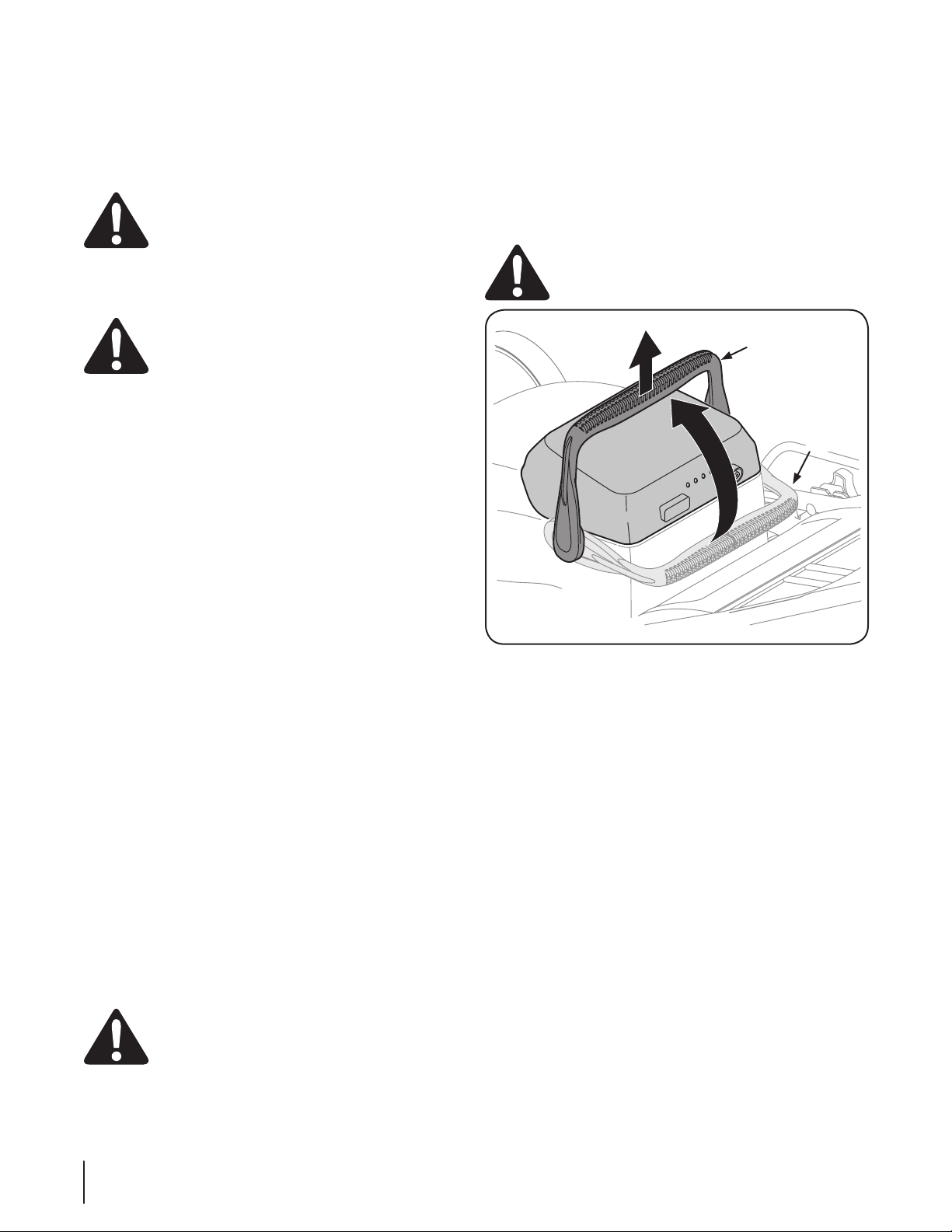
Removing the Battery
If you have two batteries, you can use one battery while the
other battery recharges. To remove the battery:
Remove the safety key.1.
Move the locking handle from the locked position to the 2.
unlocked position. See Fig. 5-3.
Lift the battery off the mower base. See Fig. 5-3.3.
WARNING: The battery is heavy. Lift with your legs
and not your back.
Using Side Discharge
Attach the side discharge chute following the instructions in the
“Assembly & Set-Up” section. When using the side discharge, the
most effective mowing pattern is one that allows the clippings to
discharge towards the uncut part of the lawn.
Using Grass Catcher
You can use the grass catcher to collect clippings while you are
operating the mower.
Attach grass catcher following instructions in the 1.
“Assembly & Set-Up” section. Grass clippings will
automatically collect in bag as you run mower. Operate
mower till grass bag is full.
Stop motor completely by releasing the blade/motor 2.
control handle. Make sure that the unit has come to a
complete stop.
Lift discharge door and pull grass bag up and away from 3.
the mower to remove the bag. Dispose of the grass
clippings and reinstall the bag when complete.
WARNING: If you strike a foreign object, stop the
motor, and remove the key. Thoroughly inspect the
mower for any damage, and repair the damage
before restarting and operating the mower.
Excessive vibration of the mower during operation is
an indication of damage. The unit should be
promptly inspected and repaired.
Figure 5-3
To seat the battery, make sure the safety key is removed, place
the battery in the battery base and turn the locking handle to the
locked position.
IMPORTANT: Use only with battery pack 725-05089.
14 se c t i O n 5— Op e r a t i O n
Page 15
Maintenance & Adjustments
6
General Recommendations
Always observe safety rules when performing any •
maintenance.
The warranty on this lawn mower does not cover items that •
have been subjected to operator abuse or negligence. To
receive full value from warranty, operator must maintain
the lawn mower as instructed here.
All adjustments should be checked at least once each •
season.
Periodically check all fasteners and make sure these are •
tight.
WARNING: Always stop the motor and remove the battery
before cleaning, lubricating or performing any repairs or
maintenance on the lawn mower.
Lubrication
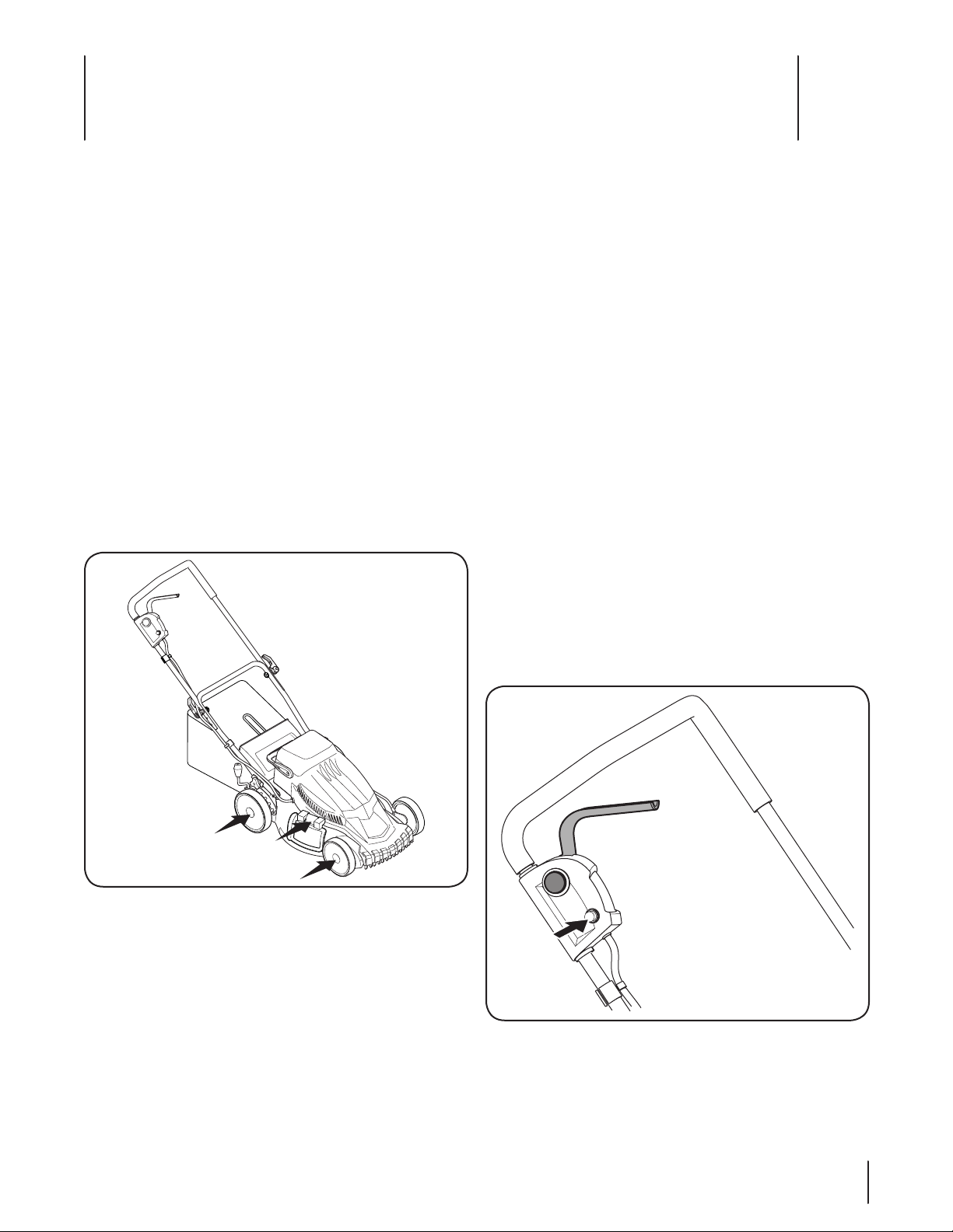
Lubricate the wheels at least once a season with light oil (or 1.
motor oil). If wheels are removed for any reason, lubricate
surface of the pivot arm and inner surface of the wheel
with light oil. See Fig. 6-1.
Deck Care
WARNING: To reduce the risk of electric shock, do not expose
the mower to water.
The underside of mower deck should be cleaned after each use
as grass clippings, leaves, dirt and other debris will accumulate.
This accumulation of grass clippings, etc., is undesirable as it will
promote rust and corrosion.
Remove any buildup of grass and leaves on or around the 1.
motor cover (do not use water). Wipe the mower clean with
a dry cloth occasionally.
If debris has built up on the underside of the unit, tilt the 2.
mower forward or on its side and scrape it clean with a
suitable tool.
IMPORTANT: Do not use a pressure washer or garden
hose to clean your unit. These may cause damage to electric
components, or the electric motor. The use of water will result in
shortened life and reduce serviceability.
Resetting Overload Protection Switch
This mower is equipped with an overload protection switch to
prevent overheating damage to the motor.
If the overload protection switch pops out:
Release the motor/blade control handle and do NOT restart 1.
the mower for at least one minute, allowing the electric
motor time to cool.
Press the overload protection switch inward to reset. See 2.
Fig. 6-2.
Figure 6-1
Lubricate the torsion spring on the side mulch plug 2.
periodically with light oil to prevent rust. See Fig. 6-1.
Figure 6-2
15
Page 16
If the overload protection switch pops out shortly after resetting:
Release the motor/blade control handle and do NOT restart 1.
the mower for at least 15 minutes to allow the electric
motor extra time to cool.
Press the overload protection switch inward to reset.2.
Restart unit.3.
NOTE: If the overload protection switch pops out
repeatedly during operation or will not remain in when
attempting to reset, you may need to raise the cutting
height to reduce the strain on the motor or recharge the
battery. If the overload protection switch will not remain in,
contact an authorized service center to arrange for repair.
Replacing Trail Shield
WARNING: Never operate mower unless the trail
shield is in place and working. Never operate mower
with damaged safety devices. Failure to do so, can
result in personal injury.
The trail shield is subject to wear and damage which could
expose moving parts or allow objects to be thrown. For safety
protection, frequently check the trail shield and replace
immediately with original equipment manufacturer’s (OEM) part
only, listed in this manual.
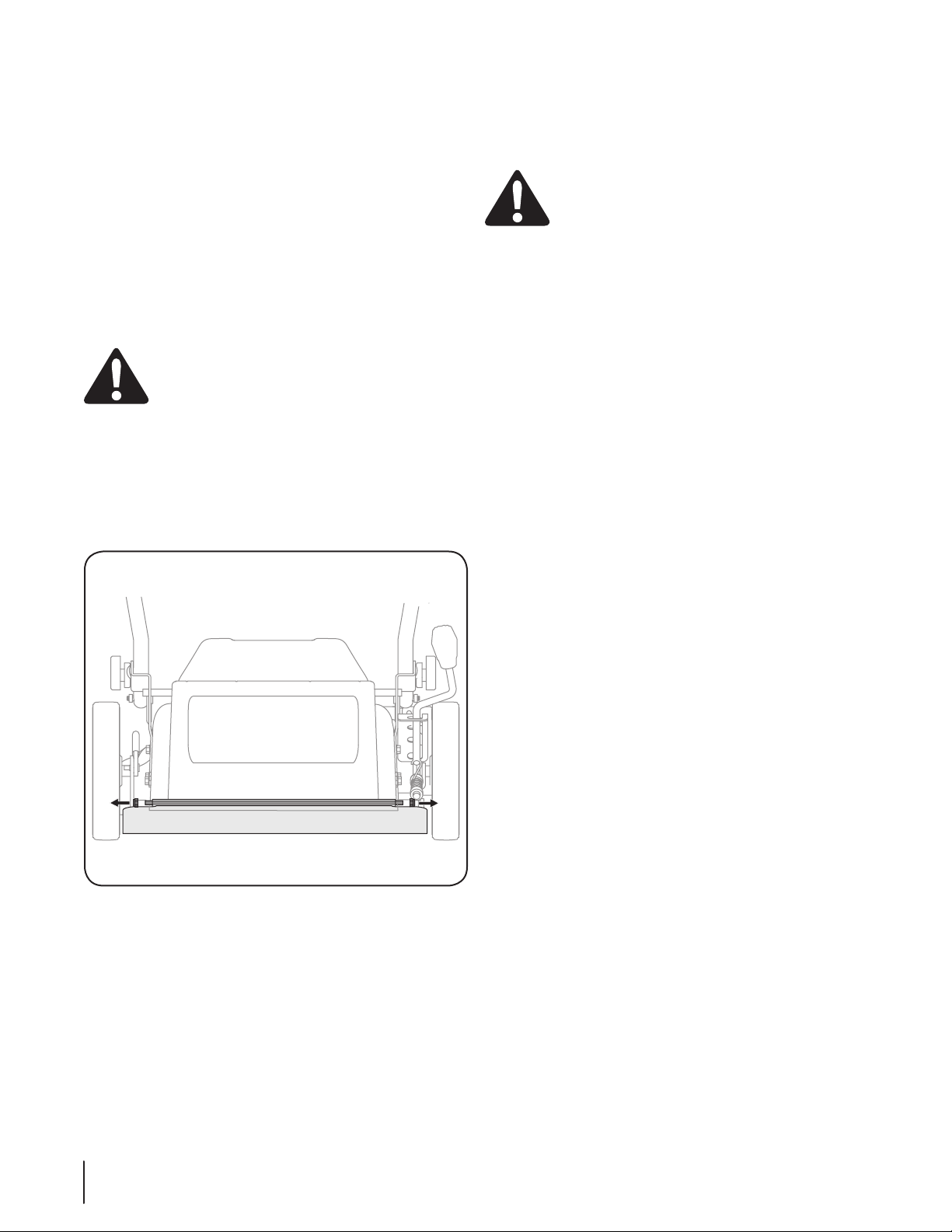
Using a 10mm wrench, hold one lock nut in place while the 1.
opposite lock nut is loosened and removed. See Fig. 6-3.
Battery Care
IMPORTANT: Replace with only the identical batteries provided
with this mower. The batteries should only be replaced by an
authorized service dealer.
WARNING: Due to a potential shock hazard, DO
NOT attempt to remove the motor/battery shroud.
There are no user serviceable parts inside. Contact
your nearest Authorized Service Center if repairs are
needed.
Figure 6-3
Remove the rod running through the trail shield and 2.
replace with new shield in the opposite order and manner
of removal.
16 se c t i O n 6— Ma i n t e n a n c e & ad j u s t M e n t s
Page 17
Service
7
Blade Care
WARNING: When removing the cutting blade for
sharpening or replacement, protect your hands with
a pair of heavy gloves or use a heavy rag to hold the
blade. Be certain to disconnect the power supply.
Periodically inspect the blade assembly for cracks, especially if
you strike a foreign object. Replace when necessary. Follow the
steps below for blade service.
Stop the motor and remove the safety key from the battery. 1.
With the battery handle locked or with the battery 2.
removed, turn the mower on its side.
Use a block of wood between blade and mower deck to 3.
prevent the blade from turning when the bolt is removed.
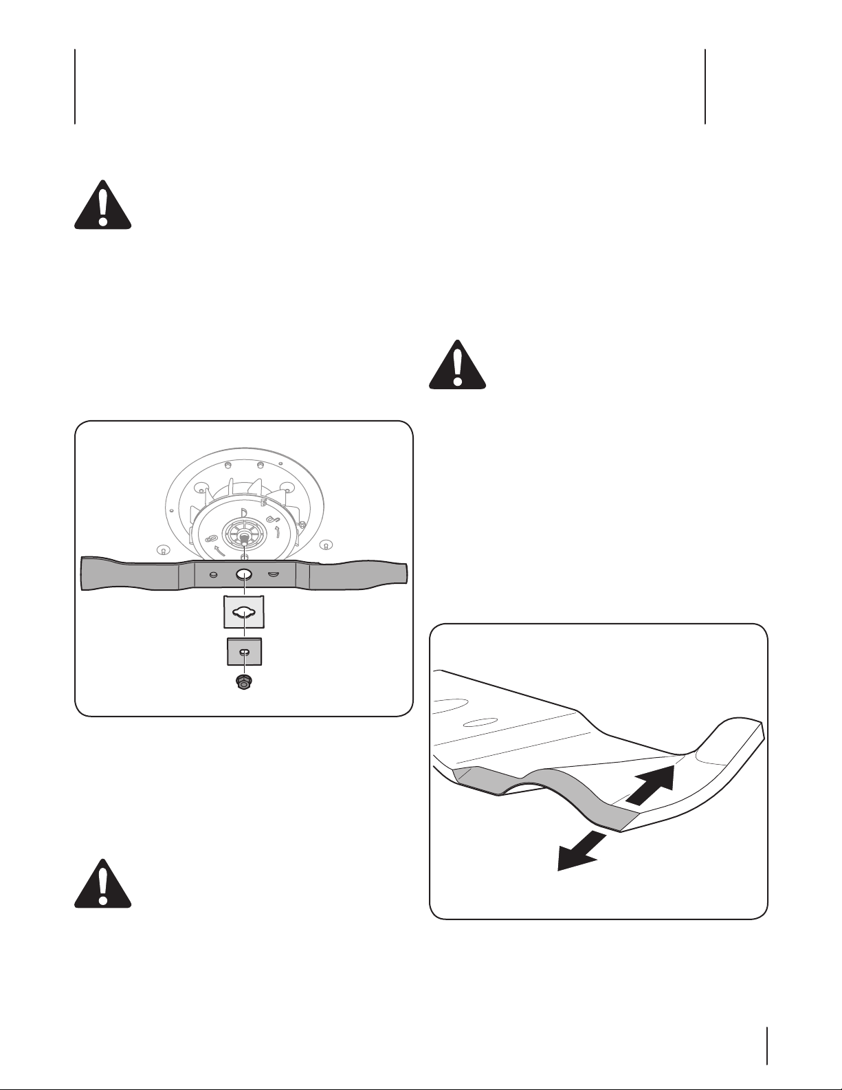
Loosen and remove the blade nut, locking plates, and 4.
blade. See Fig. 7-1.
Blade Installation
Place the cutting blade, locking plates, and blade nut on 1.
the motor shaft and thread the blade bolt in finger tight.
See Fig. 7-1.
NOTE: Make certain to replace the parts in the exact order
in which they were removed. When installing the cutting
blade, be sure it is installed with the curved ends pointing
towards the mower deck and not towards the ground.
Torque the blade bolt down using a torque wrench to 2.
assure the bolt is tightened properly. The recommended
torque for the blade bolt is 240-280 in. lbs.
WARNING: The blade hardware is not only used to
attach the blade assembly, but is also an insulated
safety device and should never be altered in any
way. If replacement is necessary, use original
equipment parts as shown in the parts list.
To insure safe operation of your unit, all nuts and bolts must be
checked periodically for correct tightness.
Blade Sharpening
To properly sharpen the cutting blades, remove equal amounts
of metal from both ends of the blades along the cutting edges,
parallel to the trailing edge, at a 25° to 30° angle. See Fig. 7-2.
NOTE: It is important that each cutting blade edge be ground
equally to maintain proper blade balance. A poorly balanced
blade will cause excessive vibration and may cause damage to
the mower and result in personal injury. The blade can be tested
by balancing it on a round shaft screwdriver. Grind metal from
the heavy side until it balances evenly.
Figure 7-1
The blade can be sharpened with a file or on a grinding 5.
wheel. Do not attempt to sharpen the blade while it is still
on the mower. When sharpening the blade, follow the
original angle of grind and grind each cutting edge equally
to keep the blade balanced. Balance the blade on a round
shaft screwdriver. Remove metal from the heavy side until
it balances evenly.
WARNING: An unbalanced blade will cause
excessive vibration when rotating at high speeds. It
may cause damage to mower, and could break
causing personal injury.
Figure 7-2
17
Page 18

Off-Season Storage
The following steps should be taken to prepare your lawn mower
for storage.
Clean and lubricate mower thoroughly as described in the •
lubrication instructions.
We do not recommend the use of a pressure washer or •
garden hose to clean your unit.
Coat mower’s cutting blade with chassis grease to prevent •
rusting.
Store mower in a dry, clean area. Do not store next to •
corrosive materials, such as fertilizer.
Wipe the cord to remove any stains or foreign substance •
such as oil.
Store mower fully charged.•
IMPORTANT: We strongly recommend the mower be
charged once every two months during storage.
IMPORTANT: Always recharge mower fully. The charger
is a two stage charger. The first stage, equalize, supplies
a higher voltage to the batteries. This helps speed charge
time and balance the charge across the individual batteries.
The second stage, float, supplies a lower voltage. This
prevents the batteries from experiencing overcharging
damage and also “tops off” the battery charge. Depending
on battery condition the equalize stage will complete
in approximately 8 hours. When the equalize stage is
complete the charger’s green LED will stop blinking. This
starts the float stage. During the float stage the chargers
green LED will be on continuously. The float stage will
“top off” the batteries in approximately 4-6 hours, again,
depending on the condition of the battery. However, a full
14 hour charge is always recommended.
18 se c t i O n 7— se r v i c e
Page 19

Troubleshooting
Problem Cause Remedy
8
Mower fails to start Key not in switch.1.
Mower stops while mowing Discharged battery.1.
Mower cutting grass
unevenly
Mower not mulching
properly
Hard to push High grass or cutting height too low.1.
Mower vibrating at higher
speed
Motor/blade control disengaged. 2.
Battery discharged.3.
Mower deck clogged with grass and debris.4.
Cutting too much grass.2.
Clogged deck. 3.
Overload protection switch is tripped.4.
Lawn rough or uneven. 1.
Dull blade. 2.
Mower deck clogged. 1.
Wet grass. 2.
Excessively high grass. 3.
Dull blade.4.
Rear of mower housing and blade dragging 2.
in heavy grass.
Bent motor shaft. 1.
Cutting blade is unbalanced. 2.
Blade is loose.3.
Insert Ignition key.1.
Depress starter button, and engage motor 2.
blade control.
Charge battery.3.
Unclog mower deck. Make certain blade is 4.
free to move.
Charge battery.1.
Raise cutting height.2.
Unclog mower deck. Raise cutting height, or 3.
cut a narrower swath.
Reset the overload protection switch 4.
following the instructions in the Maintenance
& Adjustments section of this manual.
Move the wheels to a higher cutting height 1.
position.
Sharpen or replace blade.2.
Unclog mower deck. Make certain blade is 1.
free to move.
Do not mow when grass is wet; wait until 2.
later to cut.
Mow once at a high cutting height, then 3.
mow again at desired height or make a
narrower cutting swath (1/2 width).
Sharpen or replace blade.4.
Raise cutting height.1.
Raise cutting height.2.
Stop the motor, disconnect the power source 1.
and inspect for damage. Have repaired by an
authorized service dealer.
Balance the blade by grinding each cutting 2.
edge equally.
Tighten blade bolt to 240-280 in. lbs.3.
19
Page 20
Model TB E25
20
20
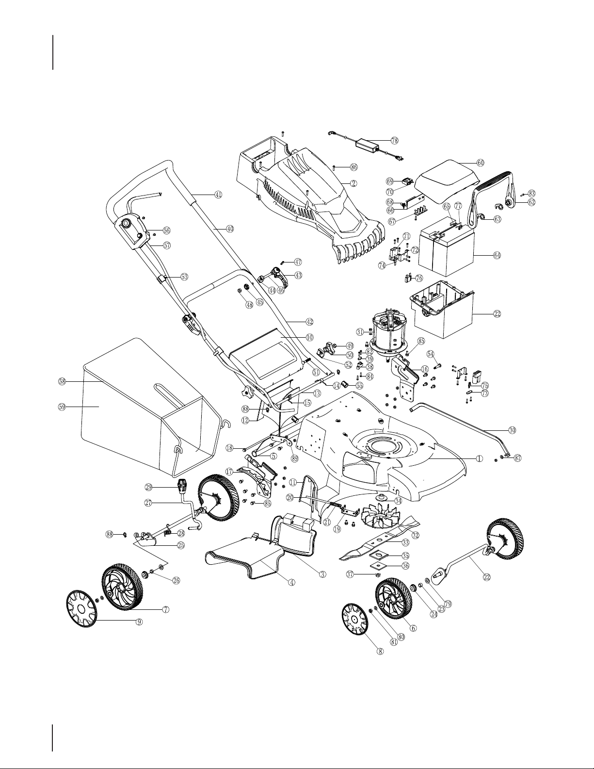
For a new battery pack, order part 725-05089.
Page 21
Model TB E25
Ref.
Part Number Description
1787-01839 Deck
2731-08261 Shroud
3 731-07619 Side Discharge Door
4 731-07620 Side Discharge Chute
5731-07621 Trail Shield
6 734-04610 Front Wheel
7 734-04611 Rear Wheel
8 731-08262 Wheel Cap
9 731-08263 Wheel Cap
10 731-07622 Rear Door
11 731-07623 Rear Ba e
12 731-0 7624 Mu lch ing Plug
13 711-05358 Rear Shaf t
14 732-04733 Spring
15 732-04734 Spring
16 787-01824 Lef t Bracket
17 78 7-0 8125 Ri ght Bra cke t
18 711-05325 Trail Shield Pin
19 787-01813 Side Discharge Bracket
20 711-05326 Side Discharge Pin
21 732- 04713 S prin g
22 611-04176 Front Shaft Assembly
23 741-04464 Front Shaft Bushing
24 741-0 4474 Bea ring
25 611-04177 Rear Shaft Assembly
26 741-04465 Rear Shaft Bushing
27 732-04735 Handle Adjust
28 732-04715 Handle Adjust Spring
29 720- 04143 Handle Adjust Knob
30 787-01826 Link Bar
31 724 -0 4095 M oto r
32 731- 07515 Fan
33 742-0 4321 Blad e
34 736-04486 Flange
35 731-07598 Was her
36 736-04487 Washer
37 712- 04237 Blade Nut
38 731-07672 Support
39 731-07673 Strain Relief
40 749-04670 Upper Handle
41 731- 07522 H andle Grip
42 749-04688 Lower Handle
43 720-04145 Quick Release
44 736-04488 Washer
45 720-04146 Quick Release Knob
Ref.
Part Number Description
46 710-05151 M8 Screw
47 715-04107 Quick Release Pin
48 712-04257 M8 Nut
49 712-04250 M6 Nut
50 720- 04147 Wing Knob
51 710- 05082 S crew
52 736 -04489 Washer
53 731-07524 Cord Clip
54 714-04088 Pin
55 731-07513 Cap
56 625-04129 Switch Box
57 725 -05156 Cor d
58 747-05304 Clamp
59 764-04096 Grassbag
60 731-07674 Batter y Pack Cover
61 731-07675 Battery Pack Housing
62 731-07676 Handle
63 787-01840 Hook
64 725-05157 Battery
65 725-05158 Connector
66 725-05159 PCB
67 725-05160 PCB Support
68 725-05161 Connector
69 725-05162 Safety Key
70 725-05163 Key Connector
71 725-05164 SA50 Connector
72 725-05165 Supporter
73 731-07678 Supporter
74 725-05170 Connector
75 725-05169 Connector
76 7 25- 05168 F use
77 725-05167 Board
78 725 -05068 Charger
79 736 -04505 Spring Washer
80 736-04506 8mm Washer
81 712-04258 M8 Nut
82 710-05156 ST4.2x16 Screw
83 710-05155 ST4.2x25 Screw
84 710-05154 ST4.8x16 Screw
85 710-05153 M6x12 Screw
86 710-05118 M5 x 12 Screw
87 714-04086 Cotter Pin
88 716-04169 10mm Lock Ring
89 787-01841 Support
21
21
Page 22

Notes
10
22
Page 23

23se c t i O n 10 — nO t e s
Page 24

MANUFACTURER’S LIMITED WARRANTY FOR
IMPORTANT: To obtain warranty coverage owner must present an
original proof of purchase and applicable maintenance records to the
servicing dealer. Please see the operator’s manual for information on
required maintenance and service intervals.
The limited warranty set forth below is given by Troy-Bilt LLC with
respect to new merchandise purchased or leased and used in the United
States and/or its territories and possessions, and by Troy-Bilt Products
Limited with respect to new merchandise purchased or leased and
used in Canada and /or its territories and possessions (either entity
respectively, “Troy-Bilt”).
Troy-Bilt warrants this product (excluding its Normal Wear Parts
and Batteries, as described below) against defects in material and
workmanship for a period of two (2) years, commencing on the date
of original retail purchase or lease and will, at its option, repair or
replace, free of charge, any part found to be defective in materials or
workmanship.
Normal Wear Parts are warranted to be free from defects in material and
workmanship for a period of thir ty (30) days from the date of original
purchase or lease. Normal wear parts include, but are not limited to
items such as: belts, blades, blade adapters, grass bags, engine oil, air
filters, spark plugs and wheels.
Batteries have a one-year prorated limited warranty against defects in
material and workmanship, with 100% replacement during the first three
months. After three months, the battery replacement credit is based on
the months remaining in the twelve (12) month period dating back to the
original date of original sale or lease. Any replacement battery will be
warranted only for the remainder of the original warranty period.
This limited warranty shall only apply if this product has been operated
and maintained in accordance with the Operator’s Manual furnished with
the product, and has not been subject to misuse, abuse, commercial
use, neglect, accident, improper maintenance, alteration, vandalism,
theft, fire, water, or damage because of other peril or natural disaster.
Damage resulting from the installation or use of any part, accessory
or attachment not approved by Troy-Bilt for use with the product(s)
covered by this manual will void your warranty as to any resulting
damage. In addition, Troy-Bilt may deny warranty coverage if the
hour meter, or any part thereof, is altered, modified, disconnected or
otherwise tampered with.
HOW TO OBTAIN SERVICE: Warranty service is available, WITH PROOF
OF PURCHASE AND APPLICABLE MAINTENANCE RECORDS, through
your local authorized service dealer. To locate the dealer in your area:
In the U.S. A.:
Check your Yellow Pages, or contact Troy-Bilt LLC at P.O. Box 361131,
Cleveland, Ohio 44136-0019, call 1-877-282- 8684
or log on to our website at www.mtdproducts.com.
In Canada :
Contact MTD Products Limited, Kitchener, ON N2G 4J1, call 1-800-6681238 or log on to our website at www.mtdcanada.com.
Without limiting the foregoing, this limited warranty does not provide
coverage in the following cases:
a. Routine maintenance items such as lubricants, filters, blade
sharpening, tune-ups, brake adjustments, clutch adjustments, deck
adjustments, and normal deterioration of the exterior finish due to
use or exposure.
b. Service completed by someone other than an authorized service
dealer.
c. Troy-Bilt does not extend any warranty for products sold or exported
outside of the United States and/or Canada, and their respective
possessions and territories, except those sold through Troy-Bilt’s
authorized channels of export distribution.
d. Replacement parts and/or accessories that are not genuine Troy-Bilt
parts.
e. Transportation charges and service calls.
f. Troy-Bilt does not warrant this product for commercial use.
There are no implied warranties, including without limitation any
implied warranty of merchantability or fitness for a particular
purpose. No warranties shall apply after the applicable period of
express written warranty above. No other express warranties beyond
those mentioned above, given by any person or entity, including a
dealer or retailer, with respect to any product, shall bind Troy-Bilt.
The exclusive remedy is repair or replacement of the product as
set forth above. The terms of this warranty provide the sole and
exclusive remedy arising from the sale and/or lease of the products
covered hereby. Troy-Bilt shall not be liable for any incidental or
consequential loss or damage including, without limitation, expenses
incurred for substitute or replacement lawn care services or for rental
expenses to temporarily replace a warranted product.
Some jurisdictions do not allow the exclusion or limitation of incidental
or consequential damages, or limitations on how long an implied
warranty lasts, so the above exclusions or limitations may not apply to
you.
In no event shall recovery of any kind be greater than the amount of the
purchase price of the product sold. Alteration of safety features of the
product shall void this warranty. You assume the risk and liability for
loss, damage, or injur y to you and your property and/or to others and
their property arising out of the misuse or inability to use the product.
This limited warranty shall not extend to anyone other than the original
purchaser or to the person for whom it was purchased as a gift.
HOW LOCAL LAWS RELATE TO THIS WARRANTY: This limited warranty
gives you specific legal rights, and you may also have other rights that
vary in different jurisdictions.
Troy-Bilt LLC, P.O. BOX 361131 CLEVELAND, OHIO 44136-0019; Phone: 1-866-840-6483, 1-330-558-7220
MTD Canada Limited - KITCHENER, ON N2G 4J1; Phone 1-800-668-1238
GDOC-100252 REV. A
 Loading...