

Page 1
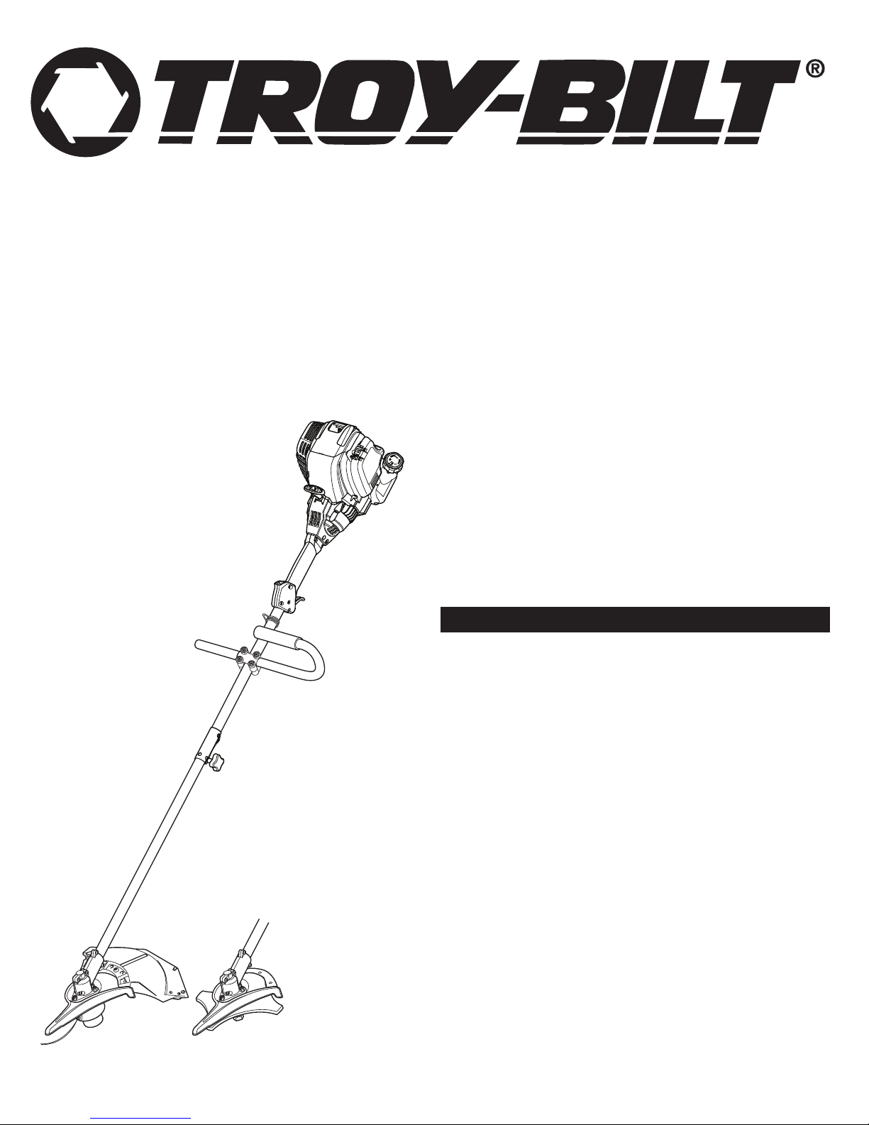
Operator’s Manual
Electric Start Capable
4-Cycle Gas Trimmer
TB590 EC
TABLE OF CONTENTS
Service Information . . . . . . . . . . . . . . . . . . . . . . . . . . . . . . . . . . . . . . . . . . . .1
Rules for Safe Operation . . . . . . . . . . . . . . . . . . . . . . . . . . . . . . . . . . . . . . .2
Know Your Unit . . . . . . . . . . . . . . . . . . . . . . . . . . . . . . . . . . . . . . . . . . . . . . .4
Assembly Instructions . . . . . . . . . . . . . . . . . . . . . . . . . . . . . . . . . . . . . . . . .4
Oil and Fuel Information . . . . . . . . . . . . . . . . . . . . . . . . . . . . . . . . . . . . . . . .5
Starting and Stopping Instructions . . . . . . . . . . . . . . . . . . . . . . . . . . . . . . . .6
Operating Instructions . . . . . . . . . . . . . . . . . . . . . . . . . . . . . . . . . . . . . . . . .6
Maintenance and Repair Instructions . . . . . . . . . . . . . . . . . . . . . . . . . . . . . .7
Cleaning and Storage . . . . . . . . . . . . . . . . . . . . . . . . . . . . . . . . . . . . . . . . . .9
Optional Accessory . . . . . . . . . . . . . . . . . . . . . . . . . . . . . . . . . . . . . . . . . .10
Troubleshooting Chart . . . . . . . . . . . . . . . . . . . . . . . . . . . . . . . . . . . . . . . .10
Specifications . . . . . . . . . . . . . . . . . . . . . . . . . . . . . . . . . . . . . . . . . . . . . . .10
Warranty Information . . . . . . . . . . . . . . . . . . . . . . . . . . . . . . . . . . . . . . . . .24
SAVE THESE INSTRUCTIONS
SERVICE INFORMATION
DO NOT RETURN THIS UNIT TO THE RETAILER. PROOF OF PURCHASE
WILL BE REQUIRED FOR WARRANTY SERVICE.
For assistance regarding the assembly, controls, operation or maintenance of
the unit, please call the Customer Support Department at 1-800-828-5500 in
the United States or 1-800-668-1238 in Canada. Additional information about
the unit can be found on our website at www.troybilt.com or www.troybilt.ca.
For service, please call the Customer Support Department to obtain a list of
authorized service dealers near you. Service on this unit, both within and after
the warranty period, should only be performed by an authorized and approved
service dealer. When servicing, use only identical replacement parts.
All information, illustrations, and specifications in this manual are based on
the latest product information available at the time of printing. We reserve
the right to make changes at any time without notice.
Copyright© 2011 MTD SOUTHWEST INC, All Rights Reserved.
769-07575 P00 12/11
Page 2
RULES FOR SAFE OPERATION
SPARK ARRESTOR NOTE
NOTE: For users on U.S. Forest Land and in the states of California, Maine,
Oregon and Washington. All U.S. Forest Land and the state of California
(Public Resources Codes 4442 and 4443), Oregon and Washington require, by
law that certain internal combustion engines operated on forest brush and/or
grass-covered areas be equipped with a spark arrestor, maintained in effective
working order, or the engine be constructed, equipped and maintained for the
prevention of fire. Check with your state or local authorities for regulations
pertaining to these requirements. Failure to follow these requirements could
subject you to liability or a fine. This unit is factory equipped with a spark
arrestor. If it requires replacement, ask your LOCAL SERVICE DEALER to
install the Accessory Part #753-05245 Muffler
Read the Operator’s Manual and follow all warnings and safety
instructions. Failure to do so can result in serious injury to the operator
and/or bystanders. FOR QUESTIONS, CALL 1-800-828-5500 IN U.S. OR
1-800-668-1238 in CANADA
The
p
ur
p
os
e
of
s
a
f
e
t
y
s
y
m
b
ol
s
i
s
t
o
a
t
t
r
a
c
t
y
our
a
t
t
e
nt
i
d
a
nge
r
s
.
The
s
a
f
e
t
y
s
y
a
t
t
e
nt
i
on a
nd
e
l
i
m
i
na
s
ub
s
t
SYMBOL MEANING
und
t
e
a
ny
it
ut
e
s
f
or
m
e
r
s
t
a
nd
d
a
nge
r
.
p
r
op
e
r
a
c
b
The
c
id
ols
i
ng.
e
,
a
The
i
ns
nt
nd
t
he
ir
e
x
p
la
na
t
s
a
f
e
t
t
r
uc
t
i
ons
p
r
e
v
e
nt
ion
ions
y
w
a
r
ni
ngs
or
w
a
r
ni
m
ngs
e
a
s
ur
e
s
d
.
,
d
o not
on
e
s
e
r
v
b
t
he
y
SAFETY ALERT: Indicates danger, warning or caution.
Attention is required in order to avoid serious personal injury. May
be used in conjunction with other symbols or pictographs.
DANGER: Failure to obey a safety warning will result in serious
injury to yourself or to others. Always follow the safety precautions
to reduce the risk of fire, electric shock and personal injury.
WARNING: Failure to obey a safety warning can result in injury
to yourself and others. Always follow the safety precautions to
reduce the risk of fire, electric shock and personal injury.
CAUTION: Failure to obey a safety warning may result in
property damage or personal injury to yourself or to others.
Always follow the safety precautions to reduce the risk of fire,
electric shock and personal injury.
NOTE: Advises you of information or instructions vital to the operation or
maintenance of the equipment.
• IMPORTANT SAFETY INSTRUCTIONS •
CALIFORNIA PROPOSITION 65
WARNING: Engine exhaust, some of its constituents and
certain finished components contain or emit chemicals known to
the State of California to cause cancer and birth defects or other
reproductive harm. Wash hands after handling.
READ ALL INSTRUCTIONS BEFORE OPERATING
WARNING:
rules. Please read these instructions before operating the unit in
order to ensure the safety of the operator and any bystanders.
Please keep these instructions for later use.
• Read the instructions carefully. Be familiar with the controls and proper
use of the unit.
• Do not operate this unit when tired, ill, or under the influence of alcohol,
drugs, or medication.
• Children and teens under the age of 15 must not use the unit, except for
teens guided by an adult.
• All guards and safety attachments must be installed properly before
operating the unit.
• Inspect the unit before use. Replace damaged parts. Check for fuel leaks.
Make sure all fasteners are in place and secure. Replace parts that are
cracked, chipped, or damaged in any way. Do not operate the unit with
loose or damaged parts.
• Carefully inspect the area before starting the unit. Remove all debris and
hard or sharp objects such as glass, wire, etc.
• Be aware of the risk of injury to the head, hands and feet.
• Clear the area of children, bystanders, and pets. At a minimum, keep all
children, bystanders, and pets outside a 50 feet (15 m.) radius; there still
may be a risk to bystanders from thrown objects. Bystanders should be
encouraged to wear eye protection. If you are approached, stop the unit
immediately.
2
When using the unit, you must follow the safety
• Use only 0.105 inch, 2.67 mm diameter original equipment manufacturer
replacement line. Never use metal-reinforced line, wire or rope. These can
break off and become dangerous projectiles.
• Squeeze the throttle control and check that it returns automatically to the
idle position. Make all adjustments or repairs before using unit.
SAFETY WARNINGS FOR GAS UNITS
WARNING:
explode if ignited. Take the following precautions:
• Store fuel only in containers specifically designed and approved for the
storage of such materials.
• Avoid creating a source of ignition for spilled fuel. Do not start the engine
until fuel vapors dissipate.
• Always stop the engine and allow it to cool before filling the fuel tank.
Never remove the fuel tank cap or add fuel when the engine is hot. Never
t
o
p
os
s
i
b
l
e
y
our
y
t
he
gi
v
e
e
c
a
r
e
f
ul
m
s
e
l
v
e
s
a
r
e
not
operate the unit without the fuel cap securely in place. Loosen the fuel
tank cap slowly to relieve any pressure in the tank.
• Add fuel in a clean, well-ventilated outdoor area where there are no sparks
or flames. Remove the fuel cap slowly, and only after the engine stops. Do
not smoke while fueling. Wipe up any spilled fuel from the unit
immediately.
• Avoid creating a source of ignition for spilled fuel. Do not start the engine
until fuel vapors dissipate.
• Move the unit at least 30 feet (9.1 m) from the fueling source and site
before starting the engine. Do not smoke. Keep sparks and open flames
away from the area while adding fuel or operating the unit.
WHILE OPERATING
• Never start or run the unit inside a closed room or building. Breathing
exhaust fumes can be fatal. Operate this unit only in a well-ventilated
outdoor area.
• Wear safety glasses or goggles that meet ANSI Z87.1 standards and are
marked as such. Wear ear/hearing protection when operating this unit.
Wear a face or dust mask if the operation is dusty.
• Wear heavy long pants, boots, gloves and a long sleeve shirt. Do not wear
loose clothing, jewelry, short pants, sandals or go barefoot. Secure hair
above shoulder level.
• The cutting attachment shield must always be in place while operating the
unit as a trimmer. Do not operate unit without both trimming lines
extended, and the proper line installed. Do not extend the trimming line
beyond the length of the shield.
• This unit has a clutch. The cutting attachment remains stationary when the
engine is idling. If it does not, have the unit adjusted by an authorized
service technician.
• Adjust the handle to your size in order to provide the best grip.
• Be sure the cutting attachment is not in contact with anything before
starting the unit.
• Use the unit only in daylight or good artificial light.
• Avoid accidental starting. Be in the starting position whenever pulling the
starter rope. The operator and unit must be in a stable position while
starting. Refer to Starting/Stopping Instructions.
• Use the right tool. Only use this tool for its intended purpose.
• Do not overreach. Always keep proper footing and balance.
• Always hold the unit with both hands when operating. Keep a firm grip on
both handles or grips.
• Keep hands, face, and feet at a distance from all moving parts. Do not
touch or try to stop the cutting attachment when it rotates.
• Do not touch the engine, gear housing or muffler. These parts get
extremely hot from operation, even after the unit is turned off.
• Do not operate the engine faster than the speed needed to cut, trim or
edge. Do not run the engine at high speed when not cutting.
• Always stop the engine when cutting is delayed or when walking from one
cutting location to another.
•
If you strike or become entangled with a foreign object, stop the engine
immediately and check for damage. Do not operate before repairing
damage. Do not operate the unit with loose or damaged parts.
• Stop the unit, switch the engine to off, and disconnect the spark plug for
maintenance or repair.
• Use only original equipment manufacturer replacement parts and
accessories for this unit. These are available from your authorized service
dealer. Use of any unauthorized parts or accessories could lead to serious
injury to the user, or damage to the unit, and void your warranty.
• Keep unit clean of vegetation and other materials. They may become
lodged between the cutting attachment and shield.
• To reduce fire hazard, replace a faulty muffler and spark arrestor. Keep the
engine and muffler free from grass, leaves, excessive grease or carbon build up.
Gasoline is highly flammable, and its vapors can
Page 3
RULES FOR SAFE OPERATION
WHILE OPERATING WITH CUTTING BLADE
• Read and understand all safety warnings before operating this unit.
• Always use the shoulder harness when using the brush blade accessory.
• Keep the J-handle between the operator and cutting attachment or blade
at all times.
• NEVER cut when the cutting blade is 30 inches (76 cm) or more above the
ground level.
• Blade thrust may occur when the spinning blade contacts an object that it
does not immediately cut. Blade thrust can be violent enough to propel
the unit and/or operator in any direction, possibly causing a loss of
control. Blade thrust can occur without warning if the blade snags, stalls
or binds. This is more likely to occur in areas where it is difficult to see the
material being cut.
• For operation with the brush blade, do not cut anything thicker than 1/2
inch or a violent kickback could occur.
• Do not attempt to touch or stop the blade when it is rotating.
• A coasting blade can cause injury while it continues to spin after the
engine is stopped or the throttle trigger is released. Maintain proper
control until the blade has completely stopped rotating.
• Do not run the unit at high speed when not cutting.
• If you strike or become entangled with a foreign object, stop the engine
immediately and check for damage. Have any damage repaired before
attempting further operations. Do not operate unit with a bent, cracked or
dull blade. Discard blades that are bent, warped, cracked or broken.
• Do not sharpen the cutting blade. Sharpening the blade can cause the
blade tip to break off while in use. This can result in severe personal injury.
Replace the blade.
• Do not use the cutting blade for edging or as an edger; severe personal
injury to yourself or others may incur. Use the cutting blade only for the
purpose described in this manual.
• Stop the engine IMMEDIATELY if you feel excessive vibration. Vibration is
a sign of trouble. Inspect thoroughly for loose nuts, bolts or damage
before continuing. Repair or replace affected parts as necessary.
AFTER USE
• Clean cutting blades with a household cleaner to remove any gum
buildup. Oil the blade with machine oil to prevent rust.
• Lock up and store the cutting blade in an appropriate area to protect the
blade from unauthorized use or damage.
OTHER SAFETY WARNINGS
• Never store a fueled unit inside a building where fumes may reach an
open flame or spark.
• Allow the engine to cool before storing or transporting. Be sure to secure
the unit while transporting.
• Store the unit in a dry area, locked up or up high to prevent unauthorized
use or damage, out of the reach of children.
• Never douse or squirt the unit with water or any other liquid. Keep handles
dry, clean and free from debris. Clean after each use, see Cleaning and
Storage instructions.
• Keep these instructions. Refer to them often and use them to instruct
other users. If you loan someone this unit, also loan them these
instructions.
SAVE THESE INSTRUCTIONS
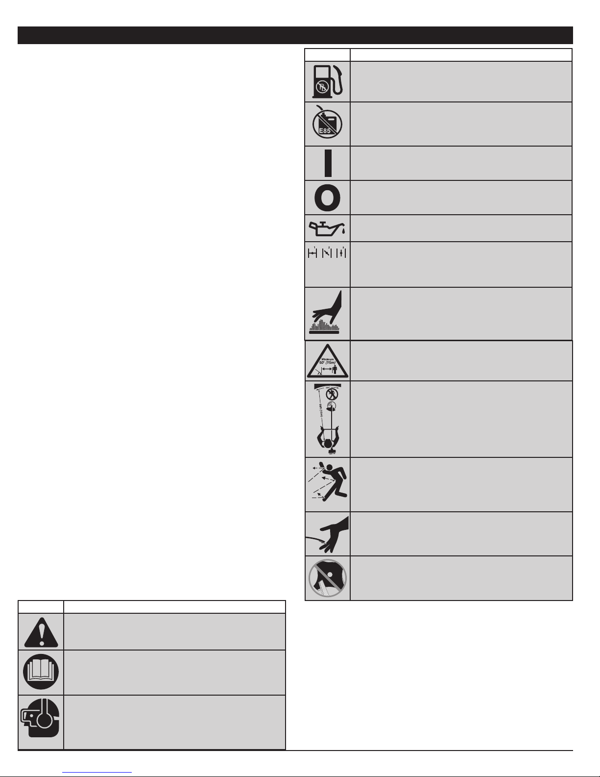
• SAFETY AND INTERNATIONAL SYMBOLS •
This operator's manual describes safety and international symbols
and pictographs that may appear on this product. Read the
operator's manual for complete safety, assembly, operating,
maintenance, and repair information.
SYMBOL MEANING
• SAFETY ALERT SYMBOL
Indicates danger, warning or caution. May be used in
conjunction with other symbols or pictographs.
• READ OPERATOR'S MANUAL
WARNING: Read the operator’s manual(s) and follow
all warnings and safety instructions. Failure to do so can
result in serious injury to the operator and/or bystanders.
• WEAR EYE AND HEARING PROTECTION
WARNING: Thrown objects and loud noise can cause
severe eye injury and hearing loss. Wear eye protection
meeting ANSI Z87.1 standards and ear protection when
operating this unit. Use a full face shield when needed.
SYMBOL MEANING
• UNLEADED FUEL
Always use clean, fresh unleaded fuel
DO NOT USE E85 FUEL IN THIS UNIT
•
WARNING: It has been proven that fuel containing
greater than 10% ethanol will likely damage this
engine and void the warranty.
• ON/OFF CONTROL
ON / START / RUN
• ON/OFF CONTROL
FF
O
• OIL
Refer to operator’s manual for the proper type of oil.
• CHOKE CONTROL
1. • FULL choke position
2. • PARTIAL choke position
3. • RUN choke position
• HOT SURFACE
WARNING: Do not touch a hot muffler, gear
housing or cylinder. You may get burned. These parts
get extremely hot from operation. They remain hot for
a short time after the unit is turned off.
• KEEP BYSTANDERS AWAY
WARNING: Keep all bystanders, especially children
and pets, at least 50 feet (15 m) from the operating area.
• TRIMMER/ BRUSHCUTTER SAFETY
WARNING: Thrown objects and rotating cutter can
cause severe injury. Keep bystanders, especially
children and pets, at least 50 feet (15 m) away from
the cutting area. The cutting attachment shield must
be used when using the trimmer cutting attachment.
• THROWN OBJECTS AND ROTATING CUTTER CAN
CAUSE SEVERE INJURY
WARNING: Do not operate without the cutting
attachment shield in place. Keep away from the
rotating cutting attachment.
• SHARP BLADE
WARNING: Sharp blade on cutting attachment
shield. To prevent serious injury, do not touch the line
cutting blade.
• BRUSHCUTTERS• REPLACE DULL BLADE
Do not sharpen the cutting blade. Sharpening the
blade can cause the blade tip to break off while in
use. This can result in severe personal injury.
3
Page 4
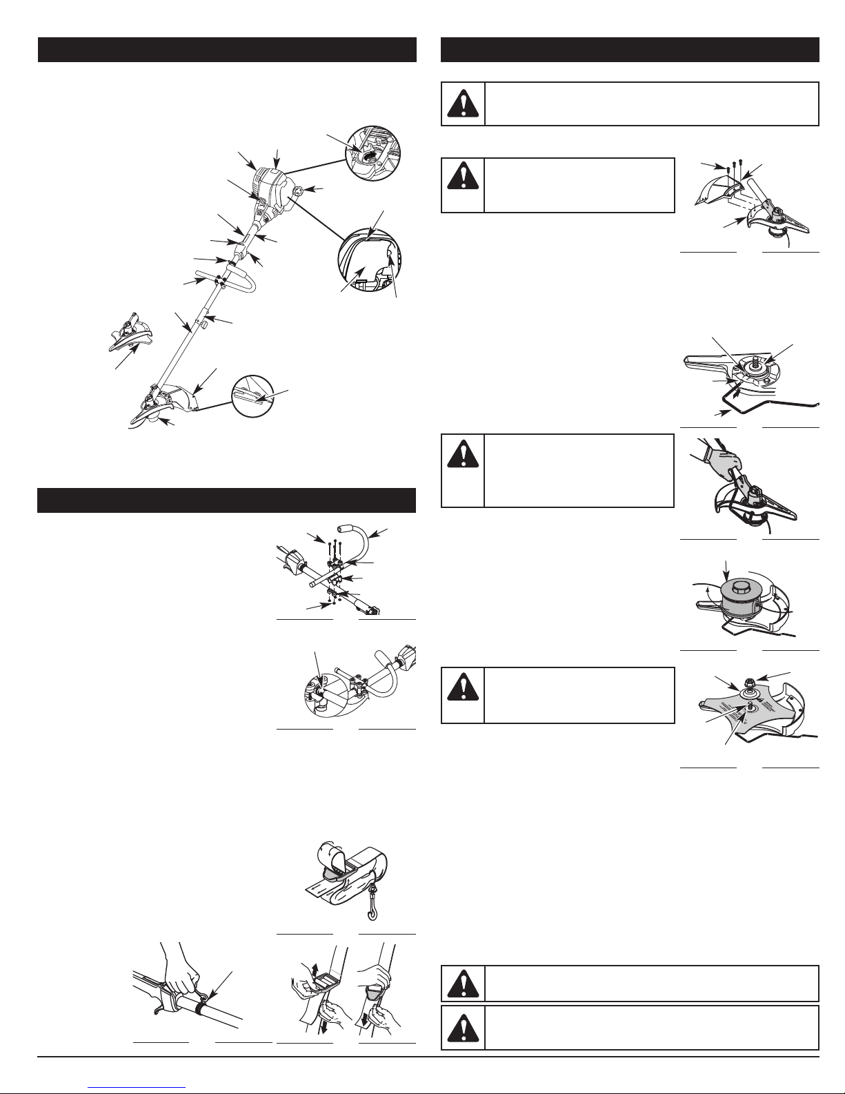
KNOW YOUR UNIT
PPLICATIONS
A
As a trimmer:
• Cutting grass and light weeds.
Edging
•
Decorative trimming around trees,
•
fences, etc.
As a brushcutter:
Cutting weeds and light brush of up
•
to 1/2 inch in diameter.
Shoulder Strap Loop
Brushcutter Blade
On/Off Control
J-Handle
haft
S
Cutting Attachment
uffler
M
Starter Rope Grip
Throttle Lockout
EZ-LINK®
Cutting Attachment Shield
Spark Plug
Throttle Control
Oil Fill Plug
haft Grip
S
Air Filter Cover
Line Cutting Blade
Fuel Cap
Choke Lever
Primer Bulb
ASSEMBLY INSTRUCTIONS
ig. 1
F
Fig. 2
Fig. 3
J Handle
Top Clamp
Middle Clamp
Bottom Clamp
INSTALL AND ADJUST THE J-HANDLE
On some units, the J-handle may be pre-
Screws
installed. In this case you must loosen screws
and adjust the handle to fit the operator. Go to
step 5 if the J-handle is pre-installed.
1. Place the J-handle between the top and
middle clamp pieces (Fig. 1).
2. While holding the three pieces together, install
uts
N
the four (4) screws through the top clamp and
into middle clamp.
NOTE: The holes in the top and middle clamp
Decal
will line up only when assembled correctly.
3. Place the clamps and the J-handle over the
shaft housing and onto the bottom clamp.
4. Hold each hex nut in the bottom clamp recess
with a finger. Start screws with a large Phillips
screwdriver. Do not tighten until you make the
handle adjustment.
5. Slide the J-handle in or out until the arrow/white line on the decal touches
the clamp assembly (Fig. 2). You must first loosen the screws if the handle
is pre-installed.
6.
While holding the unit in the operating position (Fig. 23), position the J-handle to
the location that provides you the best grip.
7. Tighten the clamp screws evenly, until the J-handle is secure.
INSTALL THE HARNESS
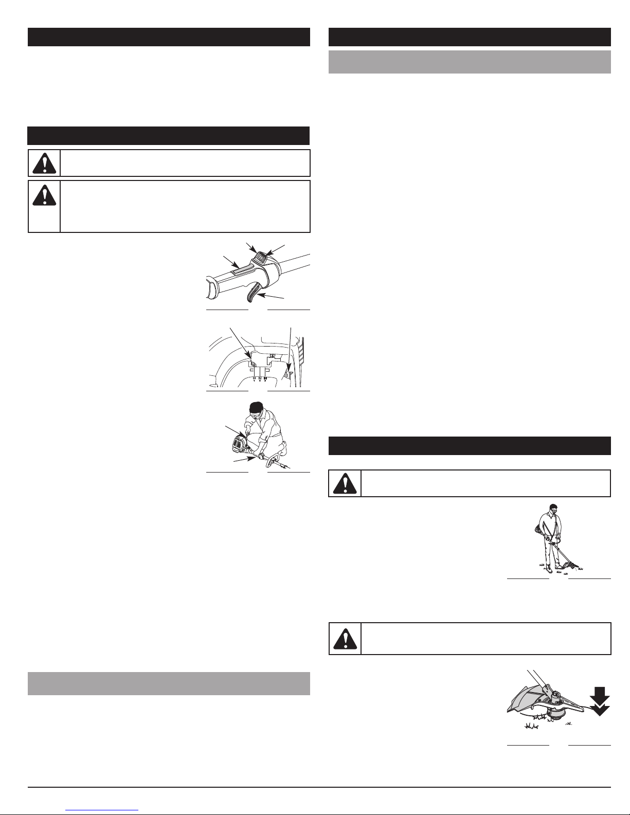
1. Push the strap through the center of the buckle.
2. Pull the strap over the cross bar and down through
the slot in the buckle (Fig. 3).
3. Put the harness on over head and onto shoulder.
Snap it on to the support fitting (Fig. 4).
4. Adjust length to fit the operator’s size. Pull tab to
lengthen, pull strap to shorten (Fig 5).
Support Fitting
ASSEMBLY INSTRUCTIONS
REMOVE AND INSTALL THE CUTTING ATTACHMENT SHIELD
WARNING:
when operating the unit with a blade. Remove the cutting attachment shield
before removing or installing the blade.
Remove the cutting attachment shield when using the unit as a
brushcutter
WARNING:
personal injury, never operate the unit as a
trimmer without the cutting attachment
shield in place.
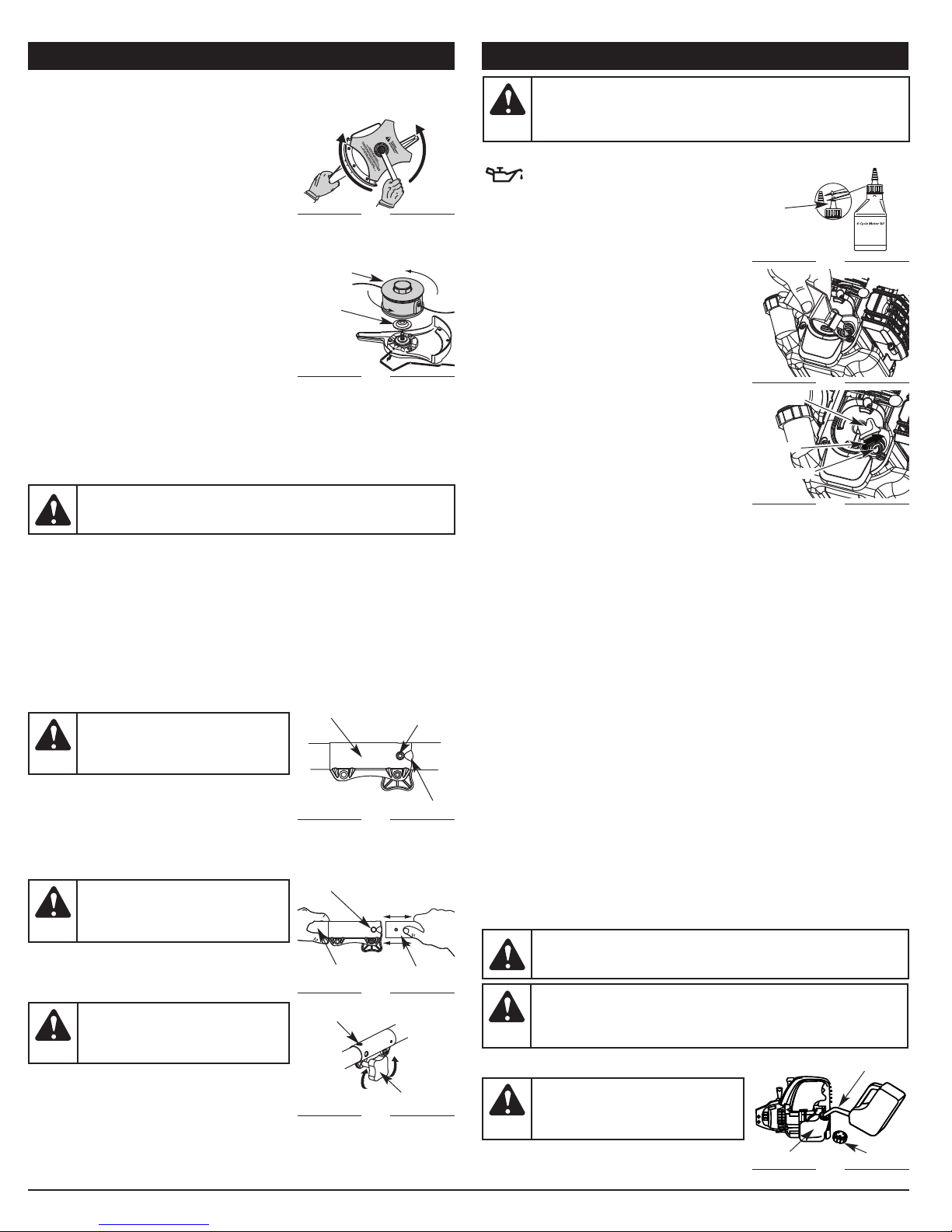
Remove the cutting attachment shield from the shield
mount by removing the three (3) screws with a flat blade
screwdriver (Fig. 6). Store parts for future use.
Install the cutting attachment shield when using the unit as a grass trimmer
Install the cutting attachment shield on the shield mount by inserting the three
(3) screws into the shield mount. Tighten securely with a flat blade screwdriver
(Fig. 6).
REMOVE THE CUTTING ATTACHMENT AND INSTALL THE CUTTING
BLADE
NOTE: To make cutting blade removal and
installation easier, place the unit on the
ground or on a work bench.
Remove the Cutting Attachment Shield
See Remove and Install the Cutting Attachment
Shield.
Remove the Cutting Attachment
DANGER:
with use. It can result in injury to the
operator. The housing remains hot for a
short time even after the unit is turned off.
Do not touch the gear housing until it has
cooled.
1. Align the shaft bushing hole with the locking
rod slot and insert the locking rod into the
bushing hole (Fig. 7).
2. Hold the locking rod in place by grasping it
next to the boom of the unit (Fig. 8).
3. While holding the locking rod, remove the
cutting attachment by turning it clockwise off
of the output shaft (Fig. 9). Store the cutting
attachment for future use.
NOTE: The blade retainer under the cutting
attachment will be used when installing the
cutting blade.
DANGER:
center, the unit will vibrate and the blade
may fly off, causing possible serious
personal injury.
Install the Cutting Blade
4. Place the cutting blade on the output shaft
bushing (Fig. 10).
5. Make sure that the cutting blade is centered on
the pilot step and sitting flat against the output shaft bushing (Fig. 10).
6. Align the shaft bushing hole with the locking rod slot and insert the locking
rod into the bushing hole (Fig. 7).
7. Put the blade retainer and nut on the output shaft (Fig. 10). Make sure that
the blade is installed correctly.
8. Tighten nut counterclockwise against the blade while holding the locking
rod (Fig. 11):
• If using a torque wrench and a 13 mm socket tighten to:
325 - 335 in•lb, 27 - 28 ft.•lb, 37 - 38 N•m.
• Without a torque wrench, use a 13 mm closed-end or socket wrench,
turning the nut until the blade retainer is snug against the shaft bushing.
Make sure that the blade is installed correctly, then rotate the nut an
additional 1/4 to 1/2 turn counterclockwise (Fig. 11).
9. Remove the locking rod from the locking rod slot.
WARNING:
not start or operate this unit with the locking rod in the locking rod slot.
The cutting attachment shield should NOT be installed
To prevent serious
Screws (3)
Shield Mount
Bushing Hole
Locking
Rod Slot
Locking
Rod
Cutting Attachment
Shield
Fig. 6
Output Shaft
Bushing
ig. 7
F
The gear housing gets hot
Fig. 8
utting Attachment
C
Fig. 9
Blade
If the cutting blade is off-
Retainer
Output
Shaft
Pilot Step
Fig. 10
To avoid serious personal injury or damage to the unit, do
Nut
Fig. 4
4
Fig. 5
WARNING:
Do not sharpen the cutting blade. Sharpening the blade
can cause the blade tip to break off while in use. This can result in severe
personal injury. Replace the blade.
Page 5
ASSEMBLY INSTRUCTIONS
REMOVE THE CUTTING BLADE AND INSTALL THE CUTTING ATTACHMENT
Remove the Cutting Blade
1. Align the shaft bushing hole with the locking
rod slot and insert the locking rod into the
bushing hole (Fig. 7).
2. Hold the locking rod in place by grasping it next
to the boom of the unit (Fig. 8).
3. While holding the locking rod, loosen the nut
on the blade by turning it clockwise with a 13
mm closed-end or socket wrench (Fig. 11).
4. Remove the nut, blade retainer and blade
(Fig. 10). Store the nut and blade together for future use in a secure place.
Store out of children’s reach.
Install the Cutting Attachment
Cutting Attachment
5. Align the shaft bushing hole with the locking
rod slot and insert the locking rod into the
shaft bushing hole (Fig. 7). Place the blade
retainer on the output shaft with the flat
Blade
Bushing
surface against the output shaft bushing
(Fig. 12). Screw the cutting attachment
counterclockwise onto the output shaft.
Tighten securely.
NOTE: The blade retainer must be installed on the output shaft in the position
shown for the cutting attachment to work correctly (Fig. 12).
6. Remove the locking rod.
7. Install the cutting attachment shield. Refer to Remove and Install the
Cutting Attachment Shield.
OPERATING THE EZ-LINK® SYSTEM
WARNING:
Before beginning to use any attachment, read and
understand the manual that came with the attachment. Follow all
safety information contained within.
The EZ-LINK® system enables the use of these optional Add-Ons:
Trimmer . . . . . . . . . . . . . . . . . . . . . . . . . . . . . . . . . . . . . . . . . . . . . . . . . . AF720
Hedge Trimmer . . . . . . . . . . . . . . . . . . . . . . . . . . . . . . . . . . . . . . . . . . . AH720
Brushcutter . . . . . . . . . . . . . . . . . . . . . . . . . . . . . . . . . . . . . . . . . . . . . . BC720*
Cultivator. . . . . . . . . . . . . . . . . . . . . . . . . . . . . . . . . . . . . . . . . . . . . . . . GC720
Edger. . . . . . . . . . . . . . . . . . . . . . . . . . . . . . . . . . . . . . . . . . . . . . . . . . . . LE720
Pole Saw . . . . . . . . . . . . . . . . . . . . . . . . . . . . . . . . . . . . . . . . . . . . . . . . PS720
Straight Shaft Trimmer. . . . . . . . . . . . . . . . . . . . . . . . . . . . . . . . . . . . . . SS725
Turbo Blower . . . . . . . . . . . . . . . . . . . . . . . . . . . . . . . . . . . . . . . . . . . . . TB720
*Do NOT use this attachment with an electric powered unit.
Installing the Cutting Attachment or Add-On
WARNING:
To avoid serious
Z-LINK® Coupler
E
personal injury and damage to the
unit, shut the unit off before
removing or installing add-ons.
NOTE: Place the unit on the ground or on a work
bench to make add-on installation or removal
easier.
1. Turn knob counterclockwise to loosen (Fig. 15).
While firmly holding the add-on, push it straight into the EZ-LINK® coupler (Fig. 14).
2.
NOTE: Aligning the release button with the guide recess will help installation (Fig. 13).
3. Turn the knob clockwise to tighten (Fig. 15).
CAUTION:
Lock the release
Primary Hole
button in the primary hole and
securely tighten the knob before
operating this unit.
For edging (when using the line head cutting
attachment with EZ-LINK® models), lock the
release button of the cutting attachment into
Upper Shaft
Housing
the 90° edging hole (Fig. 15).
90˚ Edging Hole
CAUTION:
Add-ons are to be used
(Trimmer Only)
in the primary hole only. Using the wrong
hole could lead to personal injury or
damage to the unit.
Removing the Cutting Attachment or Add-On
1. Turn the knob counterclockwise to loosen
(Fig. 15).
2. Press and hold the release button (Fig. 13).
3. While firmly holding the upper shaft housing, pull the cutting attachment or
add-on straight out of the EZ-LINK® coupler (Fig. 14).
Loosen
Top View
Fig. 11
ig. 12
F
Fig. 13
Fig. 14
Fig. 15
Tighten
elease
R
Button
Guide Recess
Lower Shaft
Housing
Knob
OIL AND FUEL INFORMATION
WARNING:
SERIOUS PERSONAL INJURY. Check and maintain the proper oil level
in the crank case; it is important and cannot be overemphasized. Check
the oil before each use and change it as needed. See Changing the Oil.
RECOMMENDED OIL TYPE
Using the proper type and weight of oil in
the crankcase is extremely important.
Check the oil before each use and change the oil
regularly. Failure to use the correct oil, or using
dirty oil, can cause premature engine wear and
failure.
Use a high-quality SAE 30 weight oil of API (American
Petroleum Institute) service class SF, SG, SH.
ADDING OIL TO CRANKCASE: INITIAL USE
NOTE: This unit is shipped without oil. In order
to avoid damage to the unit, put oil in the
crankcase before you attempt to start the
unit.
Your unit is supplied with one 3.04 fluid oz. (90
ml.) bottle of SAE 30 SF, SG, SH oil (Fig. 16).
NOTE: Save the bottle of oil. It can be used to
measure the correct amount during future oil
changes. See Changing the Oil.
1. Unscrew the top of the bottle of oil and
remove the paper seal covering the opening.
Replace the top. Next, cut the tip off the
funnel spout (Fig. 16).
2. Tip unit so that the back of the engine is
facing up in a vertical position.
3. Remove the oil fill plug from the crankcase (Fig. 18).
4. Pour the entire bottle of oil into the oil fill hole (Fig. 17).
NOTE: Never add oil to the fuel or fuel tank.
5.
Wipe up any oil that may have spilled and reinstall the oil fill plug.
Check oil before each use and change as needed. Refer to Checking the Oil Level.
RECOMMENDED FUEL TYPE
Old fuel is the primary reason for improper unit performance. Be sure to use
fresh, clean, unleaded gasoline.
NOTE: This is a four cycle engine. In order to avoid damage to the unit, do not
mix oil with gasoline.
Definition of Blended Fuels
Today's fuels are often a blend of gasoline and oxygenates such as ethanol,
methanol or MTBE (ether). Alcohol-blended fuel absorbs water. As little as 1%
water in the fuel can make fuel and oil separate or form acids when stored.
Use fresh fuel (less than 60 days old), when using alcohol-blended fuel.
Using Blended Fuels
If you choose to use a blended fuel, or its use is unavoidable, follow
recommended precautions:
• Always use fresh unleaded gasoline
• Use the fuel additive STA-BIL® or an equivalent
• Drain tank and run the engine dry before storing unit
Using Fuel Additives
The use of fuel additives, such as STA-BIL® Gas Stabilizer or an equivalent,
will inhibit corrosion and minimize the formation of gum deposits. Using a fuel
additive can keep fuel from forming harmful deposits in the carburetor for up
to six (6) months. Add 0.8 oz. (23 ml.) of fuel additive per gallon of fuel
according to the instructions on the container. NEVER add fuel additives
directly to the unit's gas tank.
FUELING THE UNIT
WARNING:
up any spilled fuel immediately. Avoid creating a source of ignition for
spilt fuel. Do not start the engine until fuel vapors dissipate.
WARNING:
explode. Always stop the engine and allow it to cool before filling the
fuel tank. Do not smoke while filling the tank. Keep sparks and open
flames at a distance from the area.
1. Remove the fuel cap (Fig. 19).
WARNING:
to avoid injury from fuel spray. Never
operate the unit without the fuel cap
securely in place.
2. Place the gas container’s spout into the fill
hole on the fuel tank (Fig. 19) and fill the tank.
NOTE: Do not overfill the tank.
OVERFILLING OIL CRANKCASE MAY CAUSE
unnel
F
Spout
Fig. 16
Fig. 17
Oil Fill Plug
-Ring
O
Oil Fill Hole
Fig. 18
Add fuel in a clean, well ventilated outdoor area. Wipe
Gasoline is extremely flammable. Ignited vapors may
Gas Can Spout
Remove fuel cap slowly
Fuel Tank
Fig. 19
Fuel Cap
5
Page 6
OIL AND FUEL INFORMATION
FUELING THE UNIT
3. Wipe up any gasoline that may have spilled.
4. Reinstall the fuel cap.
5. Move the unit at least 30 ft. (9.1 m) from the fueling source and site before
starting the engine.
NOTE: Dispose of the old gasoline in accordance to Federal, State and Local
regulations.
STARTING AND STOPPING INSTRUCTIONS
WARNING:
Carbon monoxide exhaust fumes can be lethal in a confined area.
WARNING:
starting position when pulling the starter rope (Fig. 22). To avoid
serious injury, the operator and unit must be in a stable position
while starting. Make sure that any Add-On item is installed
correctly and secure before starting the unit.
STARTING INSTRUCTIONS
1. Check the oil level in the crankcase. Refer to
Checking the Oil Level.
2. Fill the fuel tank with fresh, clean unleaded
gasoline. Refer to Fueling the Unit.
NOTE: There is no need to turn the unit on. The
On/Off Control is in the ON ( I ) position at all
times (Fig. 20).
3. Fully press and release the primer bulb 10
times, slowly. Some amount of fuel should be
visible in the primer bulb and fuel lines (Fig.
21). If you can’t see fuel in the bulb, press and
release the bulb as many times as it takes
before you can see fuel in it.
4. Place the choke lever in Position 1 (Fig. 21).
5. Crouch in the starting position (Fig. 22). Press
the throttle lockout in and squeeze the throttle
control lever. Pull the starter rope 5 times.
6. Place the choke lever in Position 2 (Fig. 21).
7.
While pressing the throttle lockout in and
squeezing the throttle control, pull the starter
rope 3 to 5 times to start the engine.
8. Keep the throttle squeezed and allow the
engine to warm up for 30 to 60 seconds.
9. Continue squeezing the throttle control, move
the choke lever to Position 3 (Fig. 21) and
continue warming the engine for an additional 60 seconds. The unit may be
used during this time.
NOTE: Unit is properly warmed up when engine accelerates without hesitation.
IF...the engine hesitates, return the choke lever to Position 2 (Fig. 21) and
continue warm-up.
IF...the engine does not start, go back to step 3.
IF...
the engine fails to start after a few attempts, place the choke lever in Position 3
and squeeze the throttle control. Pull the starter rope out with a controlled and
steady motion 3 to 8 times. The engine should start. If not, repeat.
IF THE ENGINE IS HOT... Move the choke lever to Position 2, press the
primer bulb 10 times, squeeze the throttle control and pull the starter
rope until the unit starts. Run the unit for 2-5 minutes. The unit may be
used during this time. Then move the choke lever to Position 3.
STOPPING INSTRUCTIONS
1. Release your hand from the throttle control. Allow the engine to cool
down by idling.
2. Press and hold the On/Off Stop Control switch in the OFF (O) position
until the unit comes to a complete stop (Fig. 11).
IF USING THE OPTIONAL ELECTRIC STARTER
HOW TO START THE UNIT USING THE ELECTRIC STARTER OR POWER
START BIT™ ACCESSORY.
NOTE-
This Unit Can Use an Electric Start or Power Start Bit™ Optional Accessory!
Please refer to the Electric Starter or Power Start Bit operator’s manual for
proper use of this feature. (Items Sold Separately! Please refer to page 10 of
this manual about purchasing these accessories.)
STARTING INSTRUCTIONS
1. Check the oil level in the crankcase. Refer to Checking the Oil Level.
2. Fill the fuel tank with fresh, clean unleaded gasoline. Refer to Fueling the Unit.
6
Operate this unit only in a well-ventilated outdoor area.
Avoid accidental starting. Make sure you are in the
ON (I)
Throttle
Lockout
Choke Lever
Position 1
Starter
ope
R
Throttle
Control
OR POWER START BIT™ ACCESSORY
Fig. 20
Fig. 21
ig. 22
F
FF (O)
O
Throttle
Control
rimer Bulb
P
Starting Position
STARTING AND STOPPING INSTRUCTIONS
IF USING THE OPTIONAL ELECTRIC STARTER
OR POWER START BIT™ ACCESSORY
NOTE:
There is no need to turn the unit on. The On/Off Control is in the ON ( I )
position at all times (Fig. 20).
3. Fully press and release the primer bulb 10 times, slowly. Some amount of fuel
should be visible in the primer bulb (Fig. 21). If fuel cannot be seen in the bulb,
press and release the bulb until fuel is visible.
4. Move the choke lever to Position 1 (Fig. 21).
5. Crouch in the starting position (Fig. 22). Place the electric starter or drill
into the back of the unit. Refer to the Operation section of the Electric
Starter or Power Start Bit operator’s manual.
6. Press the throttle lockout in and squeeze the throttle control lever. Press
and hold the electric starter or drill ON (I) button for 2 seconds.
7. Move the choke lever to Position 2 (Fig. 21).
8. Press the throttle lockout in and squeeze the throttle control lever, press
and hold the electric starter or drill ON (I) button for 2-second intervals until
the unit starts.
9. Continue to squeeze the throttle control, remove the electric starter or drill
from the unit and allow the engine to warm up for 30 to 60 seconds.
10.Continue squeezing the throttle control, move the choke lever to Position
3 (Fig. 21) and run the unit for an additional 60 seconds. The unit may be
used during this time.
NOTE: Unit is properly warmed up when engine accelerates without
hesitation.
IF...the engine hesitates, return the choke lever to Position 2 (Fig. 21) and
continue warm-up.
IF...the engine does not start, go back to step 3.
IF...the engine fails to start after a few attempts, place the choke lever in Position
3 and squeeze the throttle control. Press and hold the electric starter or drill
ON (I) button for 2-second intervals until the unit starts.
IF THE ENGINE IS HOT... Move the choke lever to Position 2, press the
primer bulb 10 times, squeeze the throttle control and pull the starter
rope until the unit starts. Run the unit for 2-5 minutes. The unit may be
used during this time. Then move the choke lever to Position 3.
STOPPING INSTRUCTIONS
1. Release your hand from the throttle control. Allow the engine to cool down
by idling.
2. Press and hold the On/Off Control switch in the OFF (O) position until the
unit comes to a complete stop (Fig. 20).
OPERATING INSTRUCTIONS
HOLDING THE TRIMMER
WARNING:
to reduce the risk of injury when operating this unit.
Before operating the unit, stand in the operating
position (Fig. 23). Check for the following:
• The operator is wearing eye protection and
proper clothing
• With a slightly-bent right arm, the operator’s right
hand is holding the shaft grip
• The operator’s left arm is straight, the left hand
holding the assist handle
• The unit is at waist level
• The cutting attachment is parallel to the ground and easily contacts the
grass without the need to bend over
ADJUSTING TRIMMING LINE LENGTH
WARNING:
assembly. Excessive line length will make the clutch overheat. This
may lead to serious personal injury or damage to the unit.
The Bump Head™ cutting attachment allows you to release trimming line
without stopping the engine. To release more
line, lightly tap the cutting attachment on the
ground (Fig. 24) while operating the trimmer at
high speed.
NOTE: Always keep the trimming line fully
extended. Line release becomes more difficult
as the cutting line becomes shorter.
Each time the head is bumped, about 1 inch
(25.4 mm) of trimming line is released. A blade in
the cutting attachment shield will cut the line to
the proper length if excess line is released.
For best results, tap the Bump Head™ on bare ground or hard soil. If line
release is attempted in tall grass, the engine may stall. Always keep the
Always wear eye, hearing, foot and body protection
Fig. 23
Do not remove or alter the line cutting blade
Fig. 24
Page 7

OPERATING INSTRUCTIONS
trimming line fully extended. Line release becomes more difficult as the cutting
line becomes shorter.
NOTE: Do not rest the Bump Head™ on the ground while the unit is running.
Some line breakage will occur from:
• Entanglement with foreign matter
• Normal line fatigue
• Attempting to cut thick, stalky weeds
• Forcing the line into objects such as walls or fence posts
TIPS FOR BEST TRIMMING RESULTS
• For best trimming results, operate unit at full throttle.
• Keep the cutting attachment parallel to the ground.
• Do not force the cutting attachment. Allow the tip of the line to do the
cutting, especially along walls. Cutting with more than the tip will reduce
cutting efficiency and may overload the engine.
• Cut grass over 8 inches (200 mm) by working from top to bottom in small
increments to avoid premature line wear or engine drag.
• Cutting from right to left improves the unit's cutting efficiency. Clippings are
thrown away from the operator.
• Slowly move the trimmer into and out of the cutting area at the desired
height. Move either in a forward-backward or side-to-side motion. Cutting
shorter lengths produces the best results.
• Trim only when grass and weeds are dry.
• The life of your cutting line is dependent upon proper adherence of
explained trimming techniques, what vegetation is cut, and where
vegetation is cut.
For example, the line will wear faster when trimming against a foundation wall
as opposed to trimming around a tree.
DECORATIVE TRIMMING
Decorative trimming is accomplished by
removing all vegetation around trees, posts,
fences and more.
Rotate the whole unit so that the cutting
attachment is at a 30° angle to the ground (Fig.
25).
USING THE CUTTING BLADE
WARNING:
Always wear eye, hearing, foot and body protection
to reduce the risk of injury when operating this unit.
WARNING:
Do not use the cutting blade for edging or as an
edger. Severe personal injury to yourself or others can result.
Before operating the unit with the cutting blade, stand in the operating
position (Fig. 26). Refer to Holding the Trimmer.
CUTTING BLADE OPERATING TIPS
To establish a rhythmic cutting procedure:
• Plant feet firmly, comfortably apart.
• Bring the engine to full throttle before entering the
material to be cut. At full throttle the blade has
maximum cutting power and is less likely to bind,
stall or cause blade thrust (which can result in
serious personal injury to the operator or others).
WARNING:
Blade thrust may occur when the spinning blade
contacts an object that it does not immediately cut. Blade thrust can be
violent enough to cause the unit and/or operator to be propelled in any
direction, and possibly lose control of the unit. Blade thrust can occur
without warning if the blade snags, stalls or binds. This is more likely to
occur in areas where it is difficult to see the material being cut.
• Cut while swinging the upper part of your body from left to right.
• Always release the throttle trigger and allow the engine to return to idle
speed when not cutting.
• When you are finished, always unsnap the unit from the harness before
taking off the harness.
WARNING:
The blade continues to spin after the engine is turned
off. The coasting blade can seriously cut you if accidentally touched.
• Swing the unit in the opposite direction as the blade spins, which increases
the cutting action.
• After the return swing, move forward to the next area to be cut plant your
feet again.
• The cutting blade is designed with a second cutting edge. You can use it by
removing the blade, turning it upside down, and reinstalling it.
Fig. 25
Fig. 26
OPERATING INSTRUCTIONS
WARNING:
blade can cause the blade tip to break off while in use. This can result
in severe personal injury to yourself or others. Replace the blade.
To reduce the chance of material wrapping around
the blade, follow these steps:
• Cut at full throttle
• Swing the unit into material to be cut from
your left to your right (Fig. 27)
• Avoid the material just cut as you make the
return swing
WARNING:
running or blade turning. To avoid serious personal injury, turn off
the engine. Allow the blade to stop before removing materials
wrapped around the blade shaft.
Do not sharpen the cutting blade. Sharpening the
Fig. 27
Do not clear away any cut material with the engine
MAINTENANCE AND REPAIR INSTRUCTIONS
MAINTENANCE SCHEDULE
WARNING:
or repairs with unit running. Always service and repair a cool unit.
Disconnect the spark plug wire to ensure that the unit cannot start.
Perform these required maintenance procedures at the frequency stated in
the table. These procedures should also be a part of any seasonal tune-up.
NOTE: Some maintenance procedures may require special tools or skills. If
you are unsure about these procedures take your unit to any non-road
engine repair establishment, individual or authorized service dealer.
NOTE: Maintenance, replacement, or repair of the emission control devices and
system may be performed by any non-road engine repair establishment,
individual or authorized service dealer.
NOTE: Please read the California/EPA statement that came with the unit for a
complete listing of terms and coverage for the emissions control devices,
such as the spark arrestor, muffler, carburetor, etc.
FREQUENCY MAINTENANCE REQUIRED SEE
Every 10 hours Clean and oil air filter p. 8
Change 1st 10 hours Change oil p. 8
Every 25 hours
LINE INSTALLATION
WARNING:
These can break off and become dangerous projectiles.
This section covers both SplitLine™ and
standard single line installation.
Always use original equipment manufacturer
0.105 in. (2.67 mm) replacement line. Other types
of line may make the engine overheat or fail.
There are two methods to replace the trimming
line:
• Wind the inner reel with new line
• Install a prewound inner reel
WINDING THE EXISTING INNER REEL
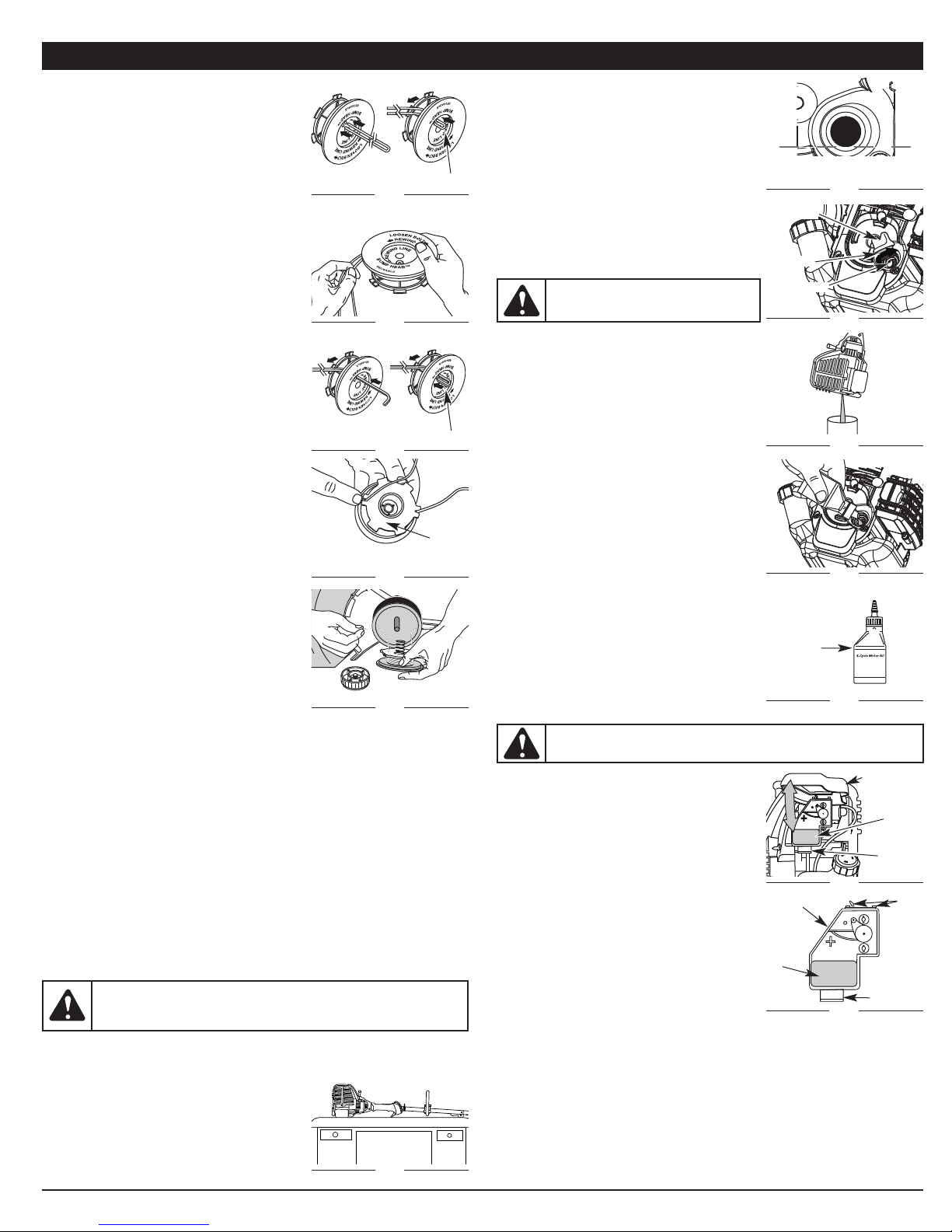
1. Hold the outer spool with one hand and
unscrew the Bump Knob clockwise (Fig. 28).
Inspect the bolt inside the bump knob to
make sure it moves freely. Replace the bump
knob if damaged.
2. Remove the inner reel from the outer spool
(Fig. 28).
3. Remove spring from the inner reel (Fig. 28).
4. Use a clean cloth to clean the the inner reel,
spring, shaft and inner surface of the outer
spool (Fig. 29).
5. Check the indexing teeth on the inner reel and
outer spool for wear (Fig. 30). If necessary,
remove burrs or replace the reel and spool.
NOTE: Always use the correct line length when
installing trimming line on the unit. The line
may not release properly if the line is too long.
To prevent serious injury, never perform maintenance
Change oil
Check rocker arm to valve clearance and adjust
Check spark plug condition and gap
Never use metal-reinforced line, wire, chain or rope.
Outer
Spool
Spring
Inner Reel
Bump Knob
Index Teeth
Bolt
Fig. 28
Fig. 29
Fig. 30
p. 8
p. 9
p. 9
7
Page 8
MAINTENANCE AND REPAIR INSTRUCTIONS
SINGLE LINE INSTALLATION
Go To Step 8 for SplitLine™ Installation
6. Take approximately 18 feet (6 m) of new
trimming line, loop it into two equal lengths.
Insert each end of the line through one of the
two holes in the inner reel (Fig. 31). Pull the line
through the inner reel so that the loop is as small
as possible.
7. Wind the lines in tight even layers, onto the reel
Fig. 31
(Fig. 32). Wind the line in the direction indicated
on the inner reel. Place your index finger
between the two lines to stop the lines from
overlapping. Do not overlap the ends of the line.
Proceed to step 11.
SPLITLINE™ INSTALLATION
8. Take approximately 9 feet (3 m) of new
trimming line. Insert one end of the line
Fig. 32
through one of the two holes in the inner reel
(Fig. 33). Pull the line through the inner reel
until only about 4 inches is left out.
9. Insert the end of the line into the open hole in
the inner reel and pull the line tight to make
the loop as small as possible (Fig. 34).
10.Before winding, split the line back about 6 inches.
11.Wind the line in tight even layers in the
direction indicated on the inner reel.
F
ig. 33
NOTE: Failure to wind the line in the direction
indicated will cause the cutting attachment to
operate incorrectly.
12.Insert the ends of the line into the two holding
slots (Fig. 34).
13.Insert the ends of the line through the eyelets
in the outer spool and place inner reel with
spring inside the outer spool (Fig. 35). Push the
inner reel and outer spool together. While
holding the inner reel and outer spool, grasp
Fig. 34
the ends and pull firmly to release the line from
the holding slots in the reel.
NOTE: The spring must be assembled on the
inner reel before reassembling the cutting
attachment.
14.Hold the inner reel in place and install the
bump knob by turning counterclockwise.
Tighten securely.
Fig. 35
INSTALLING A PREWOUND REEL
1. Hold the outer spool with one hand and unscrew the bump knob clockwise
(Fig. 28). Inspect the bolt inside the bump knob to make sure it moves
freely. Replace the bump knob if damaged.
2. Remove the old inner reel from the outer spool (Fig. 28).
3. Remove the spring from the old inner reel (Fig. 28).
4. Place the spring in the new inner reel.
NOTE: The spring must be assembled on the inner reel before reassembling
the cutting attachment.
5. Insert the ends of the line through the eyelets in the outer spool (Fig. 35).
6. Place the new inner reel inside the outer spool. Push the inner reel and outer spool
together. While holding the inner reel and outer spool, grasp the ends and pull firmly
to release the line from the holding slots in the spool.
7. Hold the inner reel in place and install the bump knob by turning
counterclockwise. Tighten securely.
CHECKING THE OIL LEVEL
WARNING:
To prevent extensive engine wear and damage to
the unit, always maintain the proper oil level in the crankcase.
Never operate the unit with a low oil level.
The importance of checking and maintaining the proper oil level in the crankcase cannot
be overemphasized. Check oil before each use:
1. Stop the engine and allow oil to drain into the
crankcase.
2. Place the engine on a flat, level surface with the
cutting head shield hanging off a work bench or
table to get a proper oil level reading (Fig. 36).
3. Keep dirt, grass clippings and other debris out
of the engine. Clean the area around the
dipstick before removing it.
Fig. 36
Loop
Loop
Tab
4. Remove the oil fill plug.
5. Look into the oil fill hole, use a flashlight if
needed. The oil should be just touching the
inner most thread (Fig. 37).6. If the oil
level is not touching the inner most thread on
the oil fill hole, add a small amount of oil to
the oil fill hole and recheck (Fig. 37). Repeat
this procedure until the oil level reaches the
inner most thread on the oil fill hole.
NOTE: Do not overfill the unit.
NOTE: Make sure the O-ring is in place on the oil fill
il Fill Plug
O
Max Oil Fill Line
Fig. 37
plug when checking and changing the oil (Fig. 38).
CHANGING THE OIL
CAUTION:
injury when handling the unit.
Wear gloves to prevent
O-Ring
Oil Fill Hole
Fig. 38
For a new engine, change the oil after the first 10
hours of operation. Change the oil while the
engine is still warm. The oil will flow freely and
carry away more impurities.
1. Unplug spark plug boot to prevent accidental
starting.
2. Remove the oil fill plug.
3. Pour the oil out of the oil fill hole and into a
container by tipping the unit to a vertical
F
ig. 39
position (Fig. 39). Allow ample time for
complete drainage.
4. Wipe up any oil residue on the unit and clean
up any oil that may have spilled. Dispose of
the oil according to Federal, State and local
regulations.
5. Refill the crankcase with 3.04 fluid ounce (90
ml) of SAE 30 SF, SG, SH oil (Fig. 40).
NOTE:
Use the bottle and spout saved from initial
Fig. 40
use to measure the correct amount of oil. The top
of the label on the bottle measures approximately
3.04 ounces (90 ml) (Fig. 41). Check the level, See
Checking the Oil Level. If the level is low, add a
small amount of oil and recheck. Do not overfill
(Fig. 37).
Fill Line
6. Replace the oil fill plug.
7. Reconnect the spark plug boot.
Fig. 41
AIR FILTER MAINTENANCE
WARNING:
To avoid serious personal injury, always turn the
unit off and allow it to cool before you clean or service it.
Cleaning the Air Filter
Air Filter Cover
Failure to maintain your air filter properly can
result in poor performance or can cause
permanent damage to your engine.
1. Open the air filter cover. Push the tab on the
Air Filter
under side of the cover inward. Then pull the
air filter cover out and up. (Fig. 42).
2. Remove the air filter (Fig. 46).
3. Wash the filter in detergent and water. Rinse
the filter thoroughly and allow it to dry.
Fig. 42
Back Plate
Tab
4. Apply enough clean SAE 30 motor oil to
lightly coat the filter.
5. Squeeze the filter to spread and remove
excess oil.
Air Filter
6. Replace the filter (Fig. 43).
NOTE: If the unit is operated without the air filter,
you will VOID the warranty.
7. Reinstall the air filter cover. Position the slots
Locking Tab
Fig. 43
on the top of the air filter cover onto the tabs at the top of the back plate
(Fig. 43).
8. Swing the cover down until the tab on the air filter backplate snaps into
place in the slot on the air filter cover (Fig. 42).
Tabs
8
Page 9

MAINTENANCE AND REPAIR INSTRUCTIONS
IDLE SPEED ADJUSTMENT
ARNING:
W
adjustments. Wear protective clothing and observe all safety
instructions to prevent serious personal injury.
The idle speed of the engine is adjustable. An idle adjustment screw is
between the air filter cover and the engine starter housing (Fig. 28).
NOTE: Careless adjustments can seriously
damage your unit. An authorized service
dealer should make carburetor adjustments.
If, after checking the fuel and cleaning the air
filter, the engine still will not idle, adjust the idle
speed screw as follows:
1. Start the engine and let it run at a high idle for
a minute to warm up. Refer to
Starting/Stopping Instructions.
2. Release the throttle trigger and let the engine idle. If the engine stops,
insert a small Phillips screwdriver in between the air filter cover and the
engine cover (Fig. 44). Turn the idle speed screw in, clockwise, 1/8 of a turn
at a time (as needed) until the engine idles smoothly.
NOTE: The cutting attachment should not rotate when the engine idles.
3. If the cutting attachment rotates when the engine idles, turn the idle speed
screw counterclockwise 1/8 of a turn at a time (as needed), to reduce idle
speed.
Checking the fuel, cleaning the air filter, and adjusting the idle speed should
solve most engine problems. If not and all of the following are true:
• the engine will not idle
• the engine hesitates or stalls on acceleration
• there is a loss of engine power
Have the carburetor adjusted by an authorized service dealer.
ROCKER ARM CLEARANCE
This SERVICE requires disassembly of the engine. If you feel unsure or
unqualified to perform this, take the unit to an authorized service center.
• The engine must be cold when checking or adjusting the valve clearance.
• This task should be performed inside, in a
clean, dust free area.
1. Remove the six (6) screws on the back of the
engine cover with a Flat-head or T-25 Torx
screwdriver (Fig. 45).
2. Disconnect the spark plug wire.
3. Clean dirt from around the spark plug.
Remove the spark plug from the cylinder
head by turning a 5/8 in. socket
counterclockwise.
4. Remove the engine cover (Fig. 45).
5. Clean dirt from around the rocker arm cover.
Remove the screw holding the rocker arm
cover with a large flat blade screwdriver or
Torx T-25 bit (Fig. 46). Remove the rocker arm
cover and gasket.
6. Pull the starter rope slowly to bring the piston
to the top of its travel, (known as top dead
center). Check that:
• The piston is at the top of its travel while
looking in the spark plug hole (Fig. 46).
• Both rocker arms move freely, and both
valves are closed.
If these statements are not true, repeat this step.
7. Slide the feeler gauge between the rocker arm
and the valve return spring. Measure the
clearance between the valve stem and rocker
arm (Fig. 47). Measure both the intake and
exhaust valves.
The recommended clearance for both intake
and exhaust is .003 – .006 in. (.076 – 0.152
mm). Use a standard automotive .005 in.
(0.127 mm) feeler gauge. The feeler gauge
should slide between the rocker arm and valve
stem with a slight amount of resistance,
without binding. See Figures 47 and 48.
8. If the clearance is not within specification:
a. Turn the adjusting nut using a 5/16 inch (8 mm) wrench or nut driver (Fig. 51).
• To increase clearance, turn the adjusting nut counterclockwise.
• To decrease clearance, turn the adjusting nut clockwise.
b. Recheck both clearances, and adjust as necessary.
The cutting attachment may spin during idle speed
dle Adjustment Screw
I
Fig. 44
View Of The Rear Engine Cover
Screws
Rocker Arm Cover
Spark Plug
Hole
Rocker
Arms
Adjusting Nut
0.003–0.006 in.
(0.076–0.152 mm)
Fig. 45
Fig. 46
Intake
Fig. 47
Fig. 48
Screws
Adjustment
Nuts
Exhaust
Rocker Arm
Valve Stem
Feeler
Gauge
ROCKER ARM CLEARANCE
9. Reinstall the rocker arm cover using a new gasket. Torque the screw to
20–30 in•lb (2.2–3.4 N•m).
10.Check the spark plug and reinstall. See Replacing the Spark Plug.
11.Replace the spark plug wire.
12.Reinstall the engine cover. Check alignment of the cover before tightening
the screws. Tighten screws.
REPLACING THE SPARK PLUG
Use a replacement part number 753-05784 or Champion® RDZ4H spark
plug. The correct air gap is 0.025 in. (0.635 mm). Remove the plug after every
25 hours of operation and check its condition.
1. Stop the engine and allow it to cool. Remove the six (6) screws on the back
of the engine cover with a Flat-head or T-25 Torx screwdriver (Fig. 48).
2. Grasp the plug wire firmly and pull the cap from the spark plug.
WARNING:
Do not sand blast,
scrape or clean electrodes. Grit in the
engine could damage the cylinder.
3. Clean dirt from around the spark plug.
Remove the spark plug from the cylinder
head by turning a 5/8 in. socket
counterclockwise.
4. Replace cracked, fouled or dirty spark plug.
.025 in.
0
(0.635 mm)
Fig. 49
Set the air gap at 0.025 in. (0.635 mm) using a feeler gauge (Fig. 52).
5. Install a correctly-gapped spark plug in the cylinder head. Turn the 5/8 in.
socket clockwise until snug.
If using a torque wrench torque to:
110-120 in.•lb. (12.3-13.5 N•m) Do not over tighten.
CLEANING AND STORAGE
CLEANING
WARNING:
unit off and allow it to cool before cleaning or servicing it.
Use a small brush to clean off the outside of the unit. Do not use strong
detergents. Household cleaners that contain aromatic oils such as pine and
lemon, and solvents such as kerosene, can damage plastic housing or handle.
Wipe off any moisture with a soft cloth.
STORAGE
• Never store the unit with fuel in the tank where fumes may reach an open
flame or spark.
• Allow the engine to cool before storing.
• Lock up the unit to prevent unauthorized use or damage.
• Store the unit in a dry, well-ventilated area.
• Store the unit out of the reach of children.
Short Term Storage (1-2 weeks)
1. Store the unit in a horizontal position. If this is not possible, store the unit
vertically with the engine at the top.
Long Term Storage
1. Drain all gasoline from the gas tank into a container. Do not use gas that
has been stored for more than 30 days. Dispose of the old gasoline in
accordance with federal, state and local regulations.
2. Start the engine and allow it to run until it stalls. This ensures that all
gasoline has been drained from the carburetor.
3. Allow the engine to cool. Remove the spark plug and put 5 drops of high
quality motor oil into the cylinder. Pull the starter rope slowly to distribute
the oil. Reinstall the spark plug.
NOTE: Remove the spark plug and drain all of the oil from the cylinder before
attempting to start the trimmer after storage.
4. Change the oil, referring to Changing the Oil. Dispose of the old oil in
accordance with federal, state and local regulations.
5. Thoroughly clean the unit and inspect for any loose or damaged parts.
Repair or replace damaged parts and
The unit is ready for storage.
To avoid serious personal injury, always turn the
tighten loose screws, nuts or bolts.
9
Page 10

OPTIONAL ACCESSORY
ELECTRIC STARTER AND POWER START BIT™ FEATURES
This unit is designed to be started with an optional electric starter or Power
Start Bit™ that are sold separately. If choosing to start the unit using one of
these features or have questions please contact your local retailer or call 1-
800-828-5500 U.S, (1-800-668-1238 Canada), for more information and
purchasing. You may also go to www.troybilt.com or www.troybilt.ca.
Electric Start Feature
Fig. 50
SPECIFICATIONS
ENGINE*
Engine Type . . . . . . . . . . . . . . . . . . . . . . . . . . . . . . . . . . . Air-Cooled, 4-Cycle
Displacement. . . . . . . . . . . . . . . . . . . . . . . . . . . . . . . . . . . . 1.8 cu. in. (29 cc)
Operating RPM . . . . . . . . . . . . . . . . . . . . . . . . . . . . . . . . . . . . . . . 6,800+ rpm
Idle Speed RPM . . . . . . . . . . . . . . . . . . . . . . . . . . . . . . . . . 2,800 - 3,600 rpm
Ignition Type . . . . . . . . . . . . . . . . . . . . . . . . . . . . . . . . . . . . . . . . . . . Electronic
Ignition Switch . . . . . . . . . . . . . . . . . . . . . . . . . . . . . . . . . . . . . Rocker Switch
Valve clearance. . . . . . . . . . . . . . . . . . . 0.003 – 0.006 in. (0.076 – 0.152 mm)
Spark Plug Gap . . . . . . . . . . . . . . . . . . . . . . . . . . . . . . 0.025 inch (0.635 mm)
Lubrication . . . . . . . . . . . . . . . . . . . . . . . . . . . . . . . . . . . . . . . . . . . SAE 30 Oil
Crankcase Oil Capacity . . . . . . . . . . . . . . . . . . . . . . . . . . . . . . 3.04 oz (90 ml)
Fuel . . . . . . . . . . . . . . . . . . . . . . . . . . . . . . . . . . . . . . . . . . . . . . . . . Unleaded
Carburetor . . . . . . . . . . . . . . . . . . . . . . . . . . . . . . . . . Diaphragm, All-Position
Starter . . . . . . . . . . . . . . . . . . . . . . . . . . . . . . . . . . . . . . . . . . . . . Auto Rewind
Muffler . . . . . . . . . . . . . . . . . . . . . . . . . . . . . . . . . . . . . . . . Baffled with Guard
Throttle . . . . . . . . . . . . . . . . . . . . . . . . . . . . . . . . . . . . . Manual Spring Return
Fuel Tank Capacity . . . . . . . . . . . . . . . . . . . . . . . . . . . . . . . . . . 14 oz (414 ml)
DRIVE SHAFT AND CUTTING ATTACHMENT*
Drive Shaft Housing. . . . . . . . . . . . . . . . . . . . . . . . . . . Steel Tube (EZ-LINK®)
Throttle Control . . . . . . . . . . . . . . . . . . . . . . . . . . . . . . . . . . Finger-Tip Trigger
Total Approximate Unit Weight (without fuel) . . . . . . . . 12-13.5 lbs (5.4-6 kg)
Cutting Mechanism. . . . . . . 4-Tooth Cutting Blade, Dual String Cutting Head
Line Spool . . . . . . . . . . . . . . . . . . . . . . . . . . . . . . . . . . . . Bump Line Releaser
Line Spool Diameter . . . . . . . . . . . . . . . . . . . . . . . . . . . . 4 inches (101.6 mm)
Trimming Line Diameter. . . . . . . . . . . . . . . . . . . . . . . 0.105 inches (2.67 mm)
Cutting Path Diameter, Trimmer Head . . . . . . . . . . . . . . . 18 inches (45.7 cm)
Cutting Path Diameter, Blade Head. . . . . . . . . . . . . . . . . . 8 inches (204 mm)
TROUBLESHOOTING
CAUSE ACTION
NGINE WILL NOT START
E
mpty fuel tank
E
rimer bulb wasn't pressed enough
P
Old fuel (over 30 days) Drain fuel tank and add fresh fuel
Fouled spark plug Replace or clean the spark plug
ngine is over heated
E
NGINE WILL NOT IDLE
E
Air filter is plugged Replace or clean the air filter
Old fuel (over 30 days) Drain fuel tank and add fresh fuel
mproper idle speed
I
NGINE WILL NOT ACCELERATE
E
Old fuel (over 30 days) Drain gas tank and add fresh fuel
Cutting attachment bound with grass
irty air filter
D
ENGINE LACKS POWER OR STALLS WHEN CUTTING
Old fuel (over 30 days) Drain fuel tank and add fresh fuel
ouled spark plug
F
he outside temperature is above 90˚ F
T
CUTTING ATTACHMENT WILL NOT ADVANCE LINE
Cutting attachment bound with grass
Cutting attachment out of line
Inner reel bound up
Cutting head dirty
Line welded
Line twisted when refilled
Not enough line is exposed
CUTTING LINE ADVANCES UNCONTROLLABLY
Oil, cleaner or lubricant in cutting head Clean and thoroughly dry the cutting head
If further assistance is required, contact your authorized service dealer.
ill fuel tank with fuel
F
ress primer bulb fully and slowly 10 times
P
Move the choke lever to Position 2,
queeze the throttle control and pull the
s
tarter rope until the unit starts. Run the
s
unit for 2-5 minutes. Then move the
hoke lever to Position 3.
c
djust according to the Idle Speed
A
Adjustment section
top the engine and clean the cutting
S
attachment
lean or replace the air filter
C
eplace or clean the spark plug
R
Move the choke lever to Position 2, press
the primer bulb 10 times, squeeze the
hrottle control and pull the starter rope
t
ntil the unit starts. Run the unit for 2-5
u
minutes. The unit may be used during
this time. Then move the choke lever to
osition 3.
P
Stop the engine and clean cutting attachment
Refill with new line
Replace the inner reel
Clean inner reel and outer spool
Disassemble, remove the welded section and rewind
Disassemble and rewind the line
Push the bump head and pull out line
until 4 inches (102 mm) of line is outside
of the cutting attachment
*All specifications are based on the latest product information available at the time
of printing. We reserve the right to make changes at any time without notice.
10
Page 11

Manuel de L’utilisateur
Désherbeuse/ Débroussailleuse
à 4-temps
TB590 EC
TABLE DES MATIÈRES
Service technique . . . . . . . . . . . . . . . . . . . . . . . . . . . . . . . . . . . . . . . . . . . .11
Consignes de sécurité . . . . . . . . . . . . . . . . . . . . . . . . . . . . . . . . . . . . . . . .12
Savoir votre unite . . . . . . . . . . . . . . . . . . . . . . . . . . . . . . . . . . . . . . . . . . . .14
Instructions de montage . . . . . . . . . . . . . . . . . . . . . . . . . . . . . . . . . . . . . . .14
Informations sur l'huile et le carburant . . . . . . . . . . . . . . . . . . . . . . . . . . . .15
Instructions de démarrage et d'arrêt . . . . . . . . . . . . . . . . . . . . . . . . . . . . .16
Mode d'emploi . . . . . . . . . . . . . . . . . . . . . . . . . . . . . . . . . . . . . . . . . . . . . .17
Entretien et réparations . . . . . . . . . . . . . . . . . . . . . . . . . . . . . . . . . . . . . . .18
Nettoyage et entreposage . . . . . . . . . . . . . . . . . . . . . . . . . . . . . . . . . . . . .20
Accesoire en option . . . . . . . . . . . . . . . . . . . . . . . . . . . . . . . . . . . . . . . . . .21
Tableau de dépannage . . . . . . . . . . . . . . . . . . . . . . . . . . . . . . . . . . . . . . . .21
Caractéristiques . . . . . . . . . . . . . . . . . . . . . . . . . . . . . . . . . . . . . . . . . . . . .21
Garantie . . . . . . . . . . . . . . . . . . . . . . . . . . . . . . . . . . . . . . . . . . . . . . . . . . .24
CONSERVEZ CES INSTRUCTIONS
SERVICE TECHNIQUE
NE RAMENEZ PAS CET APPAREIL CHEZ LE DÉTAILLANT. UNE PREUVE
D’ACHAT SERA EXIGÉE POUR TOUTE PRISE EN CHARGE DANS LE
CADRE DE LA GARANTIE.
Si vous éprouvez des difficultés à assembler ce produit ou si vous avez des
questions sur les commandes, l'utilisation ou l'entretien de cet appareil,
veuillez contacter le service à la clientèle en composant le 1-800-828-5500
aux États-Unis ou le 1-800-668-1238 au Canada. Des informations
supplémentaires sont disponibles sur notre site web : www.troybilt.com ou
www.troybilt.ca.
Pour un entretien ou une réparation, veuillez appeler le service clientèle pour
obtenir une liste complète des professionnels agréés près de chez vous.
L’entretien de cet appareil doit être confié exclusivement à un professionnel
agréé pendant et après la période de garantie. Utilisez uniquement des
pièces de rechange identiques.
Toutes les informations, illustrations et spécifications contenues dans ce manuel tiennent
compte des dernières informations techniques disponibles au moment de mettre sous
presse. Nous nous réservons le droit d'y apporter des modifications à tout moment, sans
préavis.
Copyright© 2011 MTD SOUTHWEST INC., Tous droits réservés.
769-07575 P00 12/11
Page 12

CONSIGNES DE SÉCURITÉ
PARE-ÉTINCELLES
REMARQUE : à l'intention des utilisateurs opérant dans les terres forestières
des États-Unis et dans les états de Californie, du Maine, de l'Orégon et de
Washington. Toutes les terres forestières des États-Unis et de l'état de Californie
(Codes sur les ressources publiques 4442 et 4443), de l'Orégon et de Washington
exigent de par la loi que certains moteurs à combustion interne utilisés dans des zones
couvertes de taillis ou d'herbe soient équipés d'un pare-étincelles en parfait état de
fonctionnement, ou qu'ils soient conçus, équipés et entretenus pour la prévention des
incendies. Renseignez-vous auprès des autorités de votre province ou de votre
municipalité concernant la réglementation en vigueur. Vous pourriez être passible d'une
amende ou être tenu responsable si vous ne respectez pas cette réglementation. Cet
appareil est équipé d'un pare-étincelles en usine. Si l'écran pare-étincelles, réf. 753-
05245, doit être remplacé, communiquez avec le service technique.
Lisez le(s) manuel(s) de l'utilisateur et suivez tous les avertissements et
consignes de sécurité. Vous pourriez à défaut entraîner des blessures graves
pour vous ou d'autres personnes. SI VOUS AVEZ DES QUESTIONS, APPELEZ
LE 1-800-828-5500 AUX ÉTATS-UNIS, OU LE 1-800-668-1238 AU CANADA
Les symboles de sécurité attirent votre attention sur des dangers potentiels. Ces
symboles et leurs détails explicatifs méritent que vous les lisiez et compreniez
bien. Les avertissements de sécurité ne peuvent éviter les dangers de par euxmêmes. Les consignes ou mises en garde qu'ils donnent ne remplacent pas
des mesures préventives appropriées contre les accidents.
SYMBOLE SIGNIFICATION
ALERTE DE SÉCURITÉ:
avertissement ou une mise en garde. Soyez vigilant afin d'éviter
toute blessure grave. Ce symbole peut être combiné à d'autres
symboles ou pictogrammes.
DANGER:
dommages matériels ou blessures graves pour tous. Respectez
les consignes de sécurité afin de réduire les risques d'incendie,
d'électrocution et de blessures.
l e non-respect d’un avertissement peut causer
AVERTISSEMENT:
causer dommages matériels ou blessures graves pour tous.
Respectez les consignes de sécurité afin de réduire les risques
d'incendie, d'électrocution et de blessures.
MISE EN GARDE:
causer dommages matériels ou blessures graves pour tous.
Respectez toujours les consignes de sécurité afin de réduire les
risques d'incendie, d'électrocution et de blessures.
REMARQUE: donne des informations ou des instructions vitales pour le
fonctionnement ou l'entretien de l'équipement.
• IMPORTANTES CONSIGNES DE SÉCURITÉ •
PROPOSITION DE LOI 65 DE CALIFORNIE
AVERTISSEMENT :
constituants et composants finis contiennent ou émettent des produits
chimiques connus de l’État de Californie comme étant à l’origine de
cancers, de malformations congénitales ou autres anomalies de la
reproduction. Lavez-vous les mains après manipulation.
LISEZ CETTE NOTICE INTEGRALEMENT AVANT D’UTILISER:
AVERTISSEMENT:
devez suivre les consignes de sécurité. Veuillez lire ces instructions
avant d’opérer la machine pour vous assurer de la sécurité de
l’opérateur et de tout spectateur. Veuillez conserver ces instructions
pour un usage ultérieur.
• Lisez soigneusement cette notice. Familiarisez-vous avec les commandes et la
marche à suivre pour une bonne utilisation de l'appareil.
•
N’utilisez pas cet appareil lorsque vous êtes fatigué, malade, ou sous l’influence de
l’alcool, de drogues, ou de médicaments.
• Tout enfant ou adolescent de moins de 15 ans ne doit pas utiliser cet appareil, à
moins que l'adolescent soit sous la supervision d’un adulte.
• Toutes les protections et tous les dispositifs de sécurité doivent être installés
correctement avant utilisation de l’appareil.
• Inspectez l’appareil avant utilisation. Remplacez les pièces endommagées.
Détectez les fuites de carburant éventuelles. Assurez-vous que tous les
accessoires sont bien en place. Remplacez les pièces susceptibles d’être
fissurées, ébréchées, ou endommagées. N’utilisez pas cet appareil si des pièces
ont du jeu ou sont endommagées.
• Inspectez la zone avec attention avant de démarrer cet appareil. Retirez tous les
débris et objets durs ou tranchants tels que du verre, les câbles, etc.
• Soyez conscient des risques de blessures à la tête, aux mains et aux pieds.
• Eloignez les enfants, les personnes à proximité et les animaux familiers de la
zone d’utilisation. Au minimum, faites reculer les enfants, les personnes à
12
indique un danger, un
le non-respect d’un avertissement peut
le non-respect d’un avertissement peut
La fumée d’échappement du moteur, certains
Lorsque vous utilisez la machine, vous
proximité et les animaux familiers de 15 m (50 pieds) ; il existe néanmoins un risque
de projectiles pour les personnes à proximité. Encouragez-les à porter des
lunettes de sécurité. Si quelqu’un s’approche de vous, arrêtez l’appareil
immédiatement.
• Utilisez uniquement un fil de 2,41 mm (0,095 pouces) de diamètre provenant du
fabricant. N’utilisez jamais de câbles, cordons ou pièces renforcées en métal,
qui peuvent céder et devenir des projectiles dangereux.
• Appuyez sur la manette des gaz et vérifiez que le régime du moteur revienne
automatiquement au ralenti. Effectuez tous les réglages et réparations avant
d’utiliser l’appareil.
AVERTISSEMENTS DE SÉCURITÉ CONCERNANT L’APPAREIL À GAZ
AVERTISSEMENT:
et ses vapeurs peuvent exploser si on y met le feu. Veuillez
prendre les précautions suivantes.
• Stockez uniquement le carburant dans des conteneurs prévus spécifiquement à
cet effet et approuvés pour le stockage de telles substances.
• Coupez toujours le moteur et laissez-le refroidir avant de remplir le réservoir
d’essence. Ne retirez jamais le bouchon du réservoir d’essence et ne remplissez
jamais ce dernier lorsque le moteur est chaud. Dévissez lentement le bouchon
du réservoir d’essence afin de réduire la pression avant de le remplir. Ne fumez
pas.
• Toujours mélanger et ajoutez le carburant dans un endroit bien aéré et propre, en
plein air, à l’abri des sources d’étincelles ou flammes vives. Ne fumez pas.
• Ne démarrez jamais l’appareil sans avoir bien revissé le bouchon du réservoir
d’essence.
• Évitez tout ce qui pourrait enflammer le carburant renversé. L’essence s’étant
échappée de l’appareil doit être essuyée immédiatement avant de démarrer
l'appareil. Éloignez l’appareil d’au moins 9,1 m (30 pieds) du site et de la source
du carburant avant de démarrer le moteur. Ne fumez pas.
• L'appareil ne doit pas être démarré ou utilisé à l'intérieur d'un espace ou d’un
bâtiment clos. Inhaler les fumées du pot d’échappement peut provoquer la mort.
Cet appareil doit fonctionner uniquement en extérieur, dans une zone bien aérée.
PENDANT L'UTILISATION DE L'APPAREIL
• Évitez de démarrer ou de faire marcher l'appareil à l'intérieur d'une pièce ou d'un
bâtiment fermé. La respiration de fumées d'échappement peut tuer. Ne faites
fonctionner cet appareil qu'à l'extérieur dans un endroit bien aéré.
• Portez des lunettes de sécurité conformes aux normes ANSI Z87.1 ainsi que des
protège-oreilles durant l'utilisation de l'appareil. Portez un masque facial ou
antipoussières si vous travaillez dans un lieu poussiéreux.
• Portez des pantalons épais et longs, des bottes, des gants et une chemise à
manches longues. Ne marchez pas pieds nus et évitez les vêtements lâches, bijoux,
pantalons courts et sandales. Relevez les cheveux au-dessus des épaules.
• Le protecteur d'accessoire de coupe doit toujours être en place lors de l'utilisation
de l'appareil. Ne faites pas marcher l'appareil sans que les deux fils soient bien
déployés, en supposant qu'un fil approprié a été installé. Assurez-vous que le fil ne
dépasse pas le protecteur de sécurité.
• Cet appareil est muni d'un embrayage. L'accessoire de coupe reste stationnaire
lorsque le moteur est au ralenti. Si ce n'est pas le cas, faites régler l'appareil par un
technicien agréé.
• Ajustez la poignée selon votre taille pour mieux l'agripper.
• N'utilisez l'appareil qu'en plein jour ou avec un bon éclairage artificiel.
• Évitez tout démarrage accidentel. Mettez-vous en position de démarrage chaque
fois que vous tirez sur la corde de démarrage. L'opérateur et l'appareil doivent tous
deux être en position stable à ce moment-là. Voir les Instructions de démarrage et
d'arrêt.
• Ne vous étirez pas. Tenez-vous toujours bien sur vos pieds en position d'équilibre.
• Tenez toujours l'appareil des deux mains lorsque vous le faites marcher. Agrippez
fermement les poignées avant et arrière.
• Gardez les mains, le visage et les pieds éloignés des pièces mobiles. Ne touchez
pas et n'essayez pas d'arrêter l'accessoire de coupe en rotation.
• Ne touchez pas le moteur, le boîtier d'engrenages ni le silencieux. Ces pièces
deviennent très chaudes à l'utilisation. Elles restent chaudes brièvement après
l'arrêt.
• Servez-vous des outils appropriés. N'utilisez cet outil que pour son usage prévu.
• Ne faites pas fonctionner le moteur à un régime plus élevé que nécessaire pour
couper, tailler ou faire les bordures. Ne faites pas tourner le moteur à haut régime si
vous ne vous faites pas de coupe.
• Arrêtez toujours le moteur lorsque vous suspendez la coupe ou lorsque vous vous
déplacez d'un lieu de travail vers un autre.
• Si vous heurtez un corps étranger ou que celui-ci est happé, arrêtez le moteur
immédiatement et vérifiez que rien n'a été endommagé. Ne faites pas fonctionner
avant réparation des dommages. Ne faites pas marcher l'appareil si les pièces sont
desserrées ou endommagées.
• Arrêtez et éteignez le moteur dans les cas suivants:
entretien, réparation ou changement d'accessoires ou autres.
L'essence est extrêmement inflammable
Page 13

CONSIGNES DE SÉCURITÉ
• N'utilisez que des pièces de équipement original rechange et accessoires d’origine
du fabricant pour cet appareil. Elles sont disponibles auprès de votre
concessionnaire agréé. L'utilisation de pièces ou accessoires autres que ceux de
éqiupement original peut causer des blessures graves, endommager l’appareil et
annuler sa garantie.
• Gardez l'appareil exempt d'accumulation de végétation ou autres matières. Celles-ci
peuvent rester logées entre l'accessoire de coupe et le protecteur.
• Afin de diminuer les risques d'incendie, remplacez tout
silencieux ou pare-étincelles défectueux et conservez le moteur et le silencieux
exempts d'herbe, de feuilles et d'accumulation excessive de graisse ou de carbone.
PENDANT L'UTILISATION DE LA LAME DE COUPE
• Prenez soin de bien lire et comprendre tous les avertissements de sécurité
avant de faire fonctionner cet appareil.
• Portez toujours le harnais d'épaule lorsque vous utilisez la lame à broussailles.
• Maintenez toujours la poignée entre l'opérateur et l'accessoire de coupe ou la
lame.
• Ne coupez jamais si la lame de coupe est à plus de 76 cm (30 po) au-dessus
du sol.
• Lorsque la lame pivotante frappe un objet qu'elle ne peut pas couper, elle
donne un coup brusque qui peut pousser violemment l'opérateur et l'appareil
vers n'importe quelle direction et faire perdre le contrôle de l'appareil. Ceci
peut se produire à l'improviste si la lame s'accroche, cale ou se coince. Cela
est plus susceptible de se produire dans les endroits où il est difficile de voir ce
que l'on coupe.
• Avec une lame à broussailles, ne coupez rien de plus épais que 1,3 cm (1/2
po) au risque de provoquer un recul violent.
• N'essayez pas de toucher ni d'arrêter la lame pendant qu'elle tourne.
• La lame continue de tourner à vide une fois le moteur éteint ou la manette des
gaz relâchée et peut causer des blessures graves. Gardez le contrôle jusqu'à
ce qu'elle ait complètement arrêté de tourner.
• Ne faites pas tourner l'appareil à haut régime si vous ne faites pas de coupe.
• Si vous heurtez un corps étranger ou que celui-ci est happé, arrêtez le moteur
immédiatement et vérifiez que rien n'a été endommagé. Réparez tout
dommage éventuel avant de poursuivre le travail. N'utilisez pas l'appareil si la
lame est tordue, fendillée ou émoussée. Jetez toute lame tordue, fendillée ou
émoussée.
• N'aiguisez pas la lame de coupe car son extrémité risquerait de casser à
l'usage et causer des blessures graves. Remplacez-la plutôt.
• Arrêtez le moteur IMMÉDIATEMENT si vous ressentez une vibration excessive
car cela indique un problème. Vérifiez soigneusement qu'il n'y a ni écrous ni
boulons desserrés, ni aucun dommage avant de continuer. Réparez ou
remplacez les pièces affectées au besoin.
APRÈS L'UTILISATION
• Nettoyez la lame de coupe avec un nettoyant ménager pour éliminer toute
accumulation de gomme. Lubrifiez la lame avec de l'huile mécanique contre la
rouille.
• Verrouillez et rangez la lame de coupe dans un lieu approprié pour éviter toute
utilisation indésirable ou des dommages.
AUTRES AVERTISSEMENTS DE SÉCURITÉ
• N'entreposez jamais l'appareil rempli de carburant dans un édifice où les
vapeurs peuvent atteindre une source de flammes vives ou d'étincelles.
• Laissez le moteur se refroidir avant de l'entreposer ou de le transporter.
Attachez bien l'appareil pendant le transport.
• Rangez l'appareil dans un endroit verrouillé et sec, ou élevé et sec, hors de
portée des enfants, pour éviter une utilisation indésirable ou un accident.
• Ne trempez et n'arrosez jamais l'appareil avec de l'eau ou tout autre liquide.
Gardez les poignées sèches, propres et exemptes de débris. Nettoyez après
chaque usage. Voir les sections Nettoyage et Entreposage.
• Conservez ces instructions. Consultez-les souvent et servez-vous en pour
instruire d'autres usagers. Si vous prêtez l'appareil à quelqu'un, prêtez-lui
également ces instructions.
CONSERVER CES INSTRUCTIONS
SYMBOLES DE SÉCURITÉ ET INTERNATIONAUX
Ce manuel de l'utilisateur décrit les symboles et pictogrammes de sécurité et
internationaux pouvant apparaître sur ce produit. Consultez le manuel de
l'utilisateur pour les informations concernant la sécurité, le montage, le
fonctionnement, l'entretien et les réparations.
SYMBOLE SIGNIFICATION
• SYMBOLE ALERTE DE SÉCURITÉ
Indique un danger, un avertissement ou une mise en garde.
Ce symbole peut être combiné à d'autres symboles ou
pictogrammes.
SYMBOLE SIGNIFICATION
• LISEZ LE MANUEL DE L'UTILISATEUR
VERTISSEMENT :
A
suivez tous les avertissements et consignes de sécurité. Vous
pourriez à défaut entraîner des blessures graves pour vous ou
d'autres personnes.
• PORTEZ DES PROTECTIONS (YEUX ET OREILLES)
AVERTISSEMENT : les objets projetés et les bruits
forts peuvent endommager la vue et l’ouïe. Portez une
visière de norme ANSI Z87.1-1989 et des protège-oreilles
pendant l'utilisation.
• CARBURANT SANS PLOMB
Utilisez toujours du carburant sans plomb frais et propre
• N’UTILISEZ PAS DE L’ESSENCE E85 DANS CET
APPAREIL
AVERTISSEMENT :
carburant contenant plus de 15% d’éthanol est susceptible
d’endommager ce moteur et annulera la garantie.
• COMMANDE MARCHE/ARRÊT
ALLUMAGE/DÉMARRAGE/MARCHE
• COMMANDE MARCHE/ARRÊT
ARRÊT
• NIVEAU D'HUILE
Voir le manuel de l'utilisateur pour le type d'huile approprié.
• ETRANGLEUR
1 • Position d’étranglement MAXIMUM
2 • Position d’étranglement PARTIEL
3 • Position de MARCHE
• SURFACE CHAUDE
AVERTISSEMENT : Ne touchez pas un silencieux ou
un cylindre chaud. Vous pourriez vous brûler. Ces pièces
deviennent très chaudes à l'utilisation. Elles restes chaudes
brièvement après l'arrêt.
• ÉLOIGNEZ LES SPECTATEURS
AVERTISSEMENT : éloignez tout spectateur, les
enfants et les animaux domestiques en particulier, d'au
moins 15 m (50 pi) de la zone de coupe.
• DÉSHERBEUSE/ DÉBROUISSAILLEUSE: SÉCURITÉ
AVERTISSEMENT : les objets projetés et la tête
coupante rotative peuvent causer des blessures graves.
Éloignez les spectateurs, les enfants et les animaux
domestiques en particulier, d'au moins 15m (50 pieds) de la
zone de coupe. Vous devez utiliser le protecteur
d'accessoire de coupe lorsque vous vous servez de
l'accessoire de coupe de la désherbeuse.
• LES OBJETS PROJETÉS ET LA TÊTE ROTATIVE
PEUVENT CAUSER DES BLESSURES GRAVES
AVERTISSEMENT : ne faites pas fonctionner sans
protecteur de sécurité en plastique. Tenez-vous à l'écart de
l'accessoire de coupe rotatif.
• LAME AIGUISÉE
AVERTISSEMENT : le protecteur d'accessoire de
coupe comporte une lame aiguisée. Ne touchez pas la lame
pour éviter des blessures graves.
• DÉBROUISSAILLEUSES: REMPLACEZ LA LAME
ÉMOUSSÉE
N'aiguisez pas la lame de coupe car son extrémité risquerait
de casser à l'usage et causer des blessures graves
Lisez le manuel de l'utilisateur et
.
Il a été prouvé que l’utilisation de
.
13
Page 14

SAVOIR VOTRE UNITE
APPLICATIONS
Utilisation comme désherbeuse :
Coupe d'herbe et de mauvaises
•
herbes légères.
• Coupe de bordures
• Tailler autour des arbres, des
lôtures, etc.
c
Utilisation comme débroussailleuse :
Coupe de mauvaises herbes et
•
roussailles légères de 1,3 cm
b
(1/2") de diamètre maximum
Commande Marche/Arrêt
accord de soutien
R
Poignée en J
orps de
C
l'arbre
ame à
L
broussailles avec
couvercle
Silencieux
Poignée de la
corde de
émarrage
d
Déverrouilleur de
anette des gaz
m
Protecteur d'accessoire
Accessoire de coupe
Bouchon de remplissage
Bougie
Prise de
l'arbre
Manette des gaz
EZ-LINK®
de coupe
Bouchon du
carburant
ouvercle du
C
filtre à air
Lame coupante
INSTRUCTIONS DE MONTAGE
INSTALLATION ET RÉGLAGE DE LA POIGNÉE EN J
AVERTISSEMENT :
protecteur d'accessoire de coupe pour éviter des blessures graves.
Sur quelques unités, la J-POIGNEE peut être préa installé. Dans ce cas vous devez desserrer des
vis et ajustez la poignée pour ajuster l'opérateur.
Aller marcher 5 si la J-POIGNEE est pré-a installé.
1. Placez la poignée en J entre les brides
supérieure et médiane (Fig. 1).
2. Maintenez les trois pièces ensemble et
introduisez les quatre (4) vis dans les brides
supérieure et médiane.
REMARQUE : les trous des brides supérieure et
médiane ne sont alignés que si l’assemblage
est correct.
3. Placez les brides et la poignée en J sur le
corps de l'arbre et sur la bride inférieure.
4. Tenez d’un doigt chaque écrou hex dans le
renfoncement de la bride inférieure.
Commencez à visser à l’aide d’un grand
tournevis à embout cruciforme. Ne serrez pas
avant de régler le guidon.
5. Glissez la poignée en J en un mouvement de va-et-vient jusqu'à ce que la
flèche/ligne blanche de l'autocollant touche la bride (Fig. 2).
6. Tenez l'appareil en position d’utilisation (Fig. 23), puis positionnez la
poignée en J de manière à assurer une prise idéale.
7. Serrez les vis des brides uniformément jusqu'à bien fixer la poignée.
INSTALLER LE HARNAIS
1. Faites passer la bandoulière au centre de la boucle.
2. Tirez la bandoulière par-dessus la traverse et à travers la fente de la boucle (Fig. 3).
3. Passez le harnais par-dessus la tête puis sur
l'épaule. Accrochez-le au raccord de soutien
(Fig. 4).
4. Réglez la longueur en fonction de la taille de
l'opérateur. Tirez la languette pour rallonger ou
tirez la bande pour raccourcir (Fig. 5).
14
n'utilisez jamais la désherbeuse sans
Vis (4)
Écrous
utocollant
A
Raccord de
soutien
Fig. 4
Fig. 1
Fig. 2
Fig. 3
Fig. 5
evier
L
d'étrangleur
Poire
d'amorçage
Poignée en J
Bride
supérieure
Bride médiane
Bride inférieure
INSTRUCTIONS DE MONTAGE
RETRAIT ET INSTALLATION DU PROTECTEUR D'ACCESSOIRE DE COUPE
VERTISSEMENT :
A
d'accessoire de coupe si vous utilisez l'appareil avec une lame.
Enlevez le protecteur avant d'enlever ou d'installer la lame.
Enlevez le protecteur d'accessoire de coupe lorsque vous vous servez
de l'appareil comme débroussailleuse.
AVERTISSEMENT :
d'accessoire de coupe DOIT toujours être installé lorsque vous vous servez
de l'appareil comme désherbeuse.
Retirez le protecteur d'accessoire de coupe de son support en enlevant les
trois vis à l'aide d'un tournevis à tête plate (Fig. 6). Rangez les pièces pour un
usage ultérieur.
Installez le protecteur d'accessoire de coupe
lorsque vous vous servez de l'appareil comme
désherbeuse
Installez le protecteur d'accessoire de coupe sur
son support en insérant les trois vis dans le support.
Serrez fermement avec un tournevis à tête plate
(Fig. 6).
RETIRER L’ACCESSOIRE DE COUPE ET
INSTALLER LA LAME DE COUPE
REMARQUE : pour faciliter le retrait ou l'installation de la lame ou de
l'accessoire de coupe, placez l'appareil au sol ou sur un établi.
Retrait du protecteur d'accessoire de coupe
Voir Retrait et installation du protecteur d'accessoire de coupe.
Retirer l'accessoire de coupe
DANGER :
chauffe à l'usage et peut blesser
le boîtier d'engre- nages
l'opérateur. Il reste chaud brièvement
après l'arrêt. Ne le touchez pas tant qu'il
n'a pas refroidi.
1. Alignez le trou de la bague de l'arbre avec la
fente de la tige de blocage, puis insérez la
tige dans le trou de la bague (Fig. 7).
2. Maintenez la tige de blocage en place en la
saisissant près du bras de l’appareil (Fig. 8).
3. Tout en tenant la tige de blocage, retirez
l’accessoire de coupe de l’arbre de sortie en
le tournant à droite (Fig. 9). Rangez
l’accessoire de coupe pour un usage ultérieur.
REMARQUE : la retenue de la lame sous
l’accessoire de coupe servira au moment de
l’installation de la lame de coupe.
Installer la lame de coupe
DANGER :
est décentrée, l'appareil vibrera et
si la lame de coupe
la lame pourrait s'envoler, ce qui
causerait des blessures graves.
4. Placez la lame de coupe sur la bague de
l'arbre de sortie (Fig. 10).
5. Assurez-vous que la lame de coupe est
centrée sur le pas de guidage et qu'elle
repose à plat contre la bague de l'arbre de
sortie (Fig. 10).
6. Alignez le trou de la bague de l'arbre avec la
fente de la tige de blocage, puis insérez la
tige dans le trou (Fig. 7).
7. Placez la retenue et l'écrou de la lame sur
l'arbre de sortie (Fig. 10). Assurez-vous que la lame est bien mise.
8. Vissez l’écrou vers la gauche contre la lame tout en tenant la tige de
blocage :
• Si vous utilisez une clé dynamométrique et
une douille de 13mm, vissez selon les valeurs
de couple suivantes:
325 - 335 po•lb, 27 - 28 pi•lb, 37 -38 N•m.
• Si vous n’avez pas de clé dynamométrique,
utilisez une clé fermée ou à douille de 13 mm
et tournez l'écrou jusqu'à ce que la retenue
soit bien ajustée contre la bague de l'arbre.
Assurez-vous que la lame est bien mise, puis
donnez à l'écrou entre 1/4 et 1/2 tour supplémentaire à gauche (Fig. 11).
9. Retirez la tige de blocage de sa fente.
AVERTISSEMENT :
endommager l'appareil, ne le faites pas marcher avec la tige de blocage
dans sa fente.
n'installez PAS le protecteur
pour éviter des blessures graves, le protecteur
Fig. 6
Fig. 7
ig. 8
F
Fig. 9
Fig. 10
Fig. 11
Protecteur
d'accessoire de
coupe
Bague de
l'arbre de sortie
Écrou
Serrez
Vis (3)
Support du
protecteur
Trou de la bague
e l'arbre
d
Fente de
la tige de
locage
b
Tige de
blocage
Accessoire de coupe
Retenue
de la lame
Bague de
l'arbre de
sortie
Pas de
guidage
Vue supérieure
À droite
pour éviter des blessures graves et ne pas
Page 15

INSTRUCTIONS DE MONTAGE
INFORMATIONS SUR L'HUILE ET LE CARBURANT
AVERTISSEMENT :
extrémité pourrait casser à l'usage et causer des blessures
n'aiguisez pas la lame de coupe : son
graves. Remplacez-la plutôt.
RETIRER LA LAME DE COUPE ET INSTALLER L'ACCESSOIRE DE COUPE
Retirer la lame de coupe
1. Alignez le trou de la bague de l'arbre avec la fente de la tige de blocage,
puis insérez la tige dans le trou (Fig. 7).
2. Maintenez la tige de blocage en place en la saisissant près du bras de
l’appareil (Fig. 8).
3. Tenez la tige de blocage et desserrez l'écrou de la lame en le tournant à
droite avec une clé fermée ou à douille de 13 mm (Fig. 11).
4. Retirez l'écrou, la retenue de lame et la lame (Fig. 10). Rangez l’écrou et la
lame ensemble en lieu sûr pour un usage ultérieur. Gardez hors de portée
Installer l'accessoire de coupe
5. Alignez le trou de la bague de l'arbre avec la fente de la tige de blocage, puis
insérez la tige dans le trou. (Fig. 7). Placez la retenue de lame sur l’arbre de
sortie, la partie plate reposant contre la bague de l’arbre tel qu'indiqué sur la
Fig. 12. Vissez l'accessoire de coupe à gauche sur l'arbre. Vissez bien.
ccessoire de
REMARQUE : la retenue de la lame doit être
installée sur l'arbre de sortie dans la position
indiquée pour que l’accessoire de coupe
fonctionne correctement (Fig. 12).
6. Retirez la tige de blocage.
A
oupe
c
Retenue
de la lame
7. Installez le protecteur d'accessoire de coupe.
Voir Retrait et installation du protecteur
d'accessoire de coupe.
Fig. 12
FONCTIONNEMENT DU EZ-LINK®
AVERTISSEMENT :
lire et comprendre le manuel accompagnant l’accessoire. Suivez
Avant d’utiliser tout accessoire, veuillez
toutes les informations relatives à la sécurité qui y figurent.
Le système EZ-Link® permet d'utiliser ces accessoires optionnels:
Désherbeuse. . . . . . . . . . . . . . . . . . . . . . . . . . . . . . . . . . . . . . . . . . . . . . AF720
Taille-haies. . . . . . . . . . . . . . . . . . . . . . . . . . . . . . . . . . . . . . . . . . . . . . . AH720
Débroussailleuse. . . . . . . . . . . . . . . . . . . . . . . . . . . . . . . . . . . . . . . . . . BC720*
Motoculteurde jardin. . . . . . . . . . . . . . . . . . . . . . . . . . . . . . . . . . . . . . . GC720
Coupe-bordure . . . . . . . . . . . . . . . . . . . . . . . . . . . . . . . . . . . . . . . . . . . . LE720
Scie à long manche . . . . . . . . . . . . . . . . . . . . . . . . . . . . . . . . . . . . . . . . PS720
Désherbeuse à arbre droit. . . . . . . . . . . . . . . . . . . . . . . . . . . . . . . . . . . SS725
Souffleur turbo. . . . . . . . . . . . . . . . . . . . . . . . . . . . . . . . . . . . . . . . . . . . TB720
*NE PAS utiliser cet accessoire avec un produit alimenté à l’électricité.
MISE EN GARDE :
principal sauf indication contraire de leurs manuels. L'utilisation du mauvais
Accessoire de coupe doivent utiliser le trou
trou pourrait causer des blessures graves ou endommager l'appareil.
Installation de l'accessoire de coupe ou autre
REMARQUE: pour faciliter l'installation ou le retrait d'accessoires, placez
l'appareil au sol ou sur un établi.
1. Dévissez le bouton vers la gauche (Fig. 15).
2. Tenez fermement l'accessoire et enfoncez-le
tout droit dans le coupleur EZ-Link® (Fig. 14).
Coupleur EZ-LINK®
déclenchement
REMARQUE: aligner le bouton de
déclenchement avec le renfoncement-guide
facilitera l'installation (Fig. 13).
3. Serrez le bouton en le tournant à droite (Fig. 15).
MISE EN GARDE :
bouton de déclenchement dans le trou
verrouillez le
principal et vissez bien le bouton avant
Trou principal
Renfoncement-guide
Fig. 13
de faire marcher l'appareil.
Pour couper les bordures à l’aide de la tête
d'accessoire de coupe sur les modèle EZ-Link®,
verrouillez le bouton de déclenchement de
l'accessoire de coupe dans le trou de 90° (Fig. 15).
AVERTISSEMENT :
des blessures graves, éteignez
pour éviter
l'appareil avant d'enlever ou d'installer
des accessoires.
Corps de l'arbre
supérieur
Trou de coupe de
bordures de 90°
Corps de l'arbre
Fig. 14
Retrait de l'accessoire de coupe ou autre
1. Dévissez le bouton vers la gauche (Fig. 15).
2. Appuyez sur le bouton de déclenchement et
maintenez-le enfoncé (Fig. 13).
3. Tenez fermement le corps de l'arbre supérieur et
retirez l'accessoire de coupe ou autre du
coupleur EZ-Link® (Fig. 14).
Bouton
Fig. 15
Bouton de
inférieur
AVERTISSEMENT :
MOTEUR PEUT ANTRAÎNER DES BLESSURES GRAVES. Nous ne
LE REMPLISSAGE EXCESSIF DU CARTER-
saurions trop insister sur l'importance de la vérification du niveau d'huile du
carter-moteur et de son maintien. Vérifiez l'huile avant chaque utilisation et
changez-la au besoin tel qu'indiqué dans la section Changment d'Huile.
TYPE D'HUILE RECOMMANDÉ
Il est extrêmement important d'utiliser les bons
type et indice d'huile dans le carter-moteur.
Vérifiez l'huile avant chaque utilisation et changez-la
périodiquement. Le fait de ne pas utiliser la bonne huile
ou d'utiliser une huile sale peut entraîner une usure et
use
B
d'entonnoir
une défaillance prématurées du moteur. Utilisez une
huile de haute qualité à indice SAE 30 API (American
Petroleum Institute) de type SG, SF, SH.
Fig. 16
AJOUT D'HUILE AU CARTER: MISE EN SERVICE
REMARQUE: cet appareil est livré sans huile. Pour éviter d’endommager
l’appareil, mettez de l’huile dans le carter moteur avant le démarrage.
Votre appareil est livré avec une bouteille d'huile SAE 30 SF, SG, SH de 90 ml
(3,04 oz) (Fig. 16).
REMARQUE: conservez la bouteille pour mesurer
correctement la quantité nécessaire d’huile plus
tard. Voir Changement d'huile.
1. Dévisser le bouchon de la bouteille d’huile et
retirez le papier couvrant l’ouverture.
Replacez le bouchon. Coupez la pointe de la
buse de l’entonnoir (Fig. 16).
2. Placez l'appareil sur une surface horizontale plane.
3. Retirez le bouchon / la jauge d'huile du carter-
moteur. Versez tout le contenu de la bouteille
Bouchon de
emplissage
r
Fig. 17
d'huile dans le carter-moteur (Fig. 18).
4. Versez tout le contenu de la bouteille d'huile
dans le carter-moteur (Fig. 17).
REMARQUE: n’ajoutez jamais d'huile au
carburant ni au réservoir de carburant.
5. Essuyez toute trace d'huile déversée et replacez
le bouchon de remplissage / la jauge.
oint
J
torique
Orifice de
emplissage
r
d’huile
F
ig. 18
Nous ne saurions trop insister sur l'importance de la vérification du niveau d'huile du
carter-moteur et de son maintien. Vérifiez l'huile avant chaque utilisation et changez-la
au besoin tel qu'indiqué dans la section Changment d'Huile.
TYPE DE CARBURANT RECOMMANDÉ
En général, si l'appareil ne fonctionne pas correctement, c'est que le
carburant est vieux ou mal mélangé. Prenez soin d'utiliser du carburant sans
plomb frais et propre.
REMARQUE: ceci est un moteur à quatre temps. Pour éviter d’endommager
l’appareil, ne mélangez pas l’huile avec l’essence.
Définition des carburants mélangés
Les carburants d'aujourd'hui sont souvent un mélange d'essence et d'oxygénés
comme l'éthanol, le méthanol ou l'éther MTBE. Un carburant mélangé à l'alcool
absorbe l'eau. Il suffit de 1% d'eau pour séparer le carburant et l'huile, ce qui forme
de l'acide pendant l'entreposage. Si vous devez utiliser ce type de carburant,
servez-vous de carburant frais (moins de 30 jours).
Usage de carburants mélangés
Si vous choisissez d'utiliser ou ne pouvez éviter d'utiliser un carburant mélangé,
suivez les conseils suivants :
• Utilisez toujours un mélange de carburant frais selon le manuel de l'utilisateur.
• Utilisez l'additif STA-BIL® ou un produit équivalent.
• Videz le réservoir et faites marcher le moteur jusqu'à ce qu'il soit à sec
avant d'entreposer l'appareil.
Utilisation d’additifs de carburant
L'utilisation d'additifs de carburant tel que le stabilisant d’essence STA-BIL® ou un
produit équivalent permet d'empêcher la corrosion et de minimiser la formation de
résidus de gomme. L'usage d'additifs peut empêcher le carburant de former des
dépôts nocifs dans le carburateur pendant six (6) mois maximum. Ajoutez 23 ml (0,8
oz) d'additif par 4 litres (1 gallon) de carburant selon les instructions du récipient.
N'ajoutez JAMAIS d'additifs directement dans le réservoir de l'appareil.
AJOUT DE CARBURANT
AVERTISSEMENT :
bien aéré en plein air. Essuyez immédiatement tout déversement de
Ajoutez du carburant dans un lieu propre et
carburant. Évitez de mettre le feu au carburant déversé. Ne démarrez
pas le moteur avant dissipation des vapeurs de carburant.
AVERTISSEMENT :
les vapeurs qui s'en dégagent peuvent exploser si on y met le feu. Arrêtez
L'essence est extrêmement inflammable et
toujours le moteur et laissez-le refroidir avant de remplir le réservoir. Ne
fumez pas en remplissant le réservoir. Éloignez toute source d'étincelles
ou de flammes vives de la zone.
15
Page 16

INFORMATIONS SUR L'HUILE ET LE CARBURANT
AJOUT DE CARBURANT
VERTISSEMENT :
A
bouchon du réservoir lentement pour ne
Enlevez le
pas être blessé par les jets d'essence.
Ne faites pas marcher l'appareil sans
que le bouchon soit bien mis.
1. Déposez le bouchon à essence (Fig. 19).
Réservoir
2. Placez le bec du récipient d’essence dans l’orifice du réservoir (Fig. 19) et
remplissez celui-ci.
REMARQUE: Ne remplissez pas trop le réservoir.
3. Essuyez tout déversement d’essence.
4. Remettez le bouchon du réservoir.
5. Éloignez l'appareil d'au moins 9,1 m (30 pi) de la source et du site de
ravitaillement en carburant avant de démarrer le moteur.
REMARQUE:
Éliminez le vieux carburant conformément aux règlements fédéral,
provincial et municipal en vigueur.
Bec du récipient d'essence
Fig. 19
INSTRUCTIONS DE DÉMARRAGE ET ARRÊT
AVERTISSEMENT :
endroit bien aéré. Les émanations d’oxyde de carbone dans un
endroit confiné peuvent être mortelles.
AVERTISSEMENT :
vous en position de démarrage lorsque vous tirez sur la corde de
démarrage (Fig. 22). L'opérateur et l'appareil doivent tous deux être en
position stable pour éviter des blessures graves. Vérifiez la bonne
installation de l'accessoire avant le démarrage de l'appareil.
INSTRUCTIONS DE DÉMARRAGE
1. Vérifiez le niveau d'huile dans le carter
moteur. Voir Vérification du niveau d'huile.
2. Remplissez le réservoir d’essence sans
plomb propre et frais. Voir Ajout de
Carburant.
REMARQUE : Il n’est pas nécessaire de faire
démarrer la machine. La commande
démarrage et arrêt est en position démarrage
(I) en permanence (Fig. 20).
3. Pressez et relâchez la poire d’amorçage à 10
reprises, lentement. Une certaine quantité de
carburant devrait être visible dans la poire
d’amorçage et les conduites de carburant
(Fig. 21). Si du carburant ne peut pas être vu
dans l'ampoule, la presse et le dégagement
l'ampoule jusqu'à ce que le carburant soit
évident.
4. Mettez le levier d'étrangleur en Position 1(Fig. 21).
5. Accroupissez-vous en position démarrage (Fig.
22). Appuyez sur le verrouillage des gaz et
appuyez sur le levier de contrôle des gaz. Tirez
vivement le lanceur à cinq reprises.
6. Mettez le levier d'étrangleur en Position 2(Fig. 21).
7. Appuyez sur la commande des gaz, tirez
vivement le lanceur jusqu’à 3 to 5 fois pour
démarrer le moteur.
8. Maintenez la manette des gaz enfoncée et laissez le moteur chauffer
pendant 30 à 60 secondes.
9. Tout en gardant enfoncée la manette des gaz, placez le levier
d'étranglement dans la Position 3 (Fig. 21) et laissez le moteur se
réchauffer encore pendant 60 secondes. Pendant ce temps l’appareil peut
être utilisé.
REMARQUE : La machine est bien chauffée lorsque le moteur accélère sans
hésitation.
SI... le moteur hésite, remettez le levier d'étranglement en Position 2 et
continuez à le chauffer.
SI... le moteur ne démarre pas, retournez à l’étape 3.
SI... le moteur ne démarre pas après plusieurs tentatives, placez le levier
d’étranglement dans la Position 3 et enfoncez la manette des gaz.
Enfoncez à plusieurs reprises pendant 2 secondes le bouton de
démarrage électrique ou de mise en MARCHE de la perceuse (I) jusqu’à
ce que le moteur démarre.
SI LE MOTEUR EST CHAUD... mettez le levier d’étranglement en Position 2,
pressez la poire d’amorçage à 10 reprises, pressez la manette des gaz, et
maintenez enfoncé pendant 2 secondes le bouton de démarrage
électrique ou de mise en MARCHE de la perceuse (I) jusqu’à ce que le
moteur démarre. Laissez tourner le moteur pendant 2 à 5 minutes.
16
n’utiliser l’outil qu’à l’extérieur, dans un
évitez tout démarrage accidentel. Tenez-
Démarrage (I)
Déverrouilleur de
manette des gaz
Levier
d'étrangleur
Poignée de
la corde de
démarrage
Manette
des gaz
Fig. 20
Fig. 21
Fig. 22
Bouchon du
arburant
c
rrêt (O)
A
Manette
es gaz
d
oire d'amorçage
P
Position de
démarrage
INSTRUCTIONS DE DÉMARRAGE ET ARRÊT
L’appareil peut être utilisé pendant cet intervalle. Puis mettez le levier
d’étranglement en Position 3.INSTRUCTIONS D'ARRÊT
1. Relâchez la manette des gaz. Laissez le moteur se refroidir au ralenti.
2. Appuyez sur la commande Marche/Arrêt Stop et maintenez-la en position
ARRÊT (O) jusqu'à ce que le moteur s’arrête complètement (Fig. 10).
SI VOUS UTILISEZ LE DEMARREUR ELECTRIQUE
OU POWER START BIT™ DISPONIBLES EN OPTION
COMMENT DÉMARRER L’APPAREIL À L’AIDE DES ACCESSOIRES DE
DÉMARRAGE ÉLECTRIQUE OU POWER START BIT™
REMARQUE : Cet appareil peut utiliser les accessoires de démarrage
électrique ou Power Start Bit™ disponibles en option.
Veuillez consulter le manuel de l’utilisateur du démarreur électrique ou de
l'embout de démarreur électrique Power Start Bit™ pour savoir
comment utiliser correctement ces fonctionnalités. (Articles vendus
séparément. Reportez-vous à la page 21 de ce manuel pour plus
d’informations sur l'achat de ces accessoires.)
INSTRUCTIONS DE DÉMARRAGE
1. Vérifiez le niveau d'huile dans le carter moteur. Voir Vérification du niveau
d'huile.
2. Remplissez le réservoir d’essence sans plomb propre et frais. Voir Ajout
de Carburant.
REMARQUE : Il n’est pas nécessaire de faire démarrer la machine. La
commande démarrage et arrêt est en position démarrage (I) en
permanence (Fig. 10).
3. Lentement, appuyez 10 fois de suite sur la poire d’amorce. Une certaine
quantité de carburant devrait être visible dans la poire d'amorce (Fig. 11).
Si l’essence n’est pas visible dans la poire d’amorce, poussez et
relâchez la poire jusqu’à ce que l’essence soit visible.
4. Mettez le levier d’étranglement en Position 1 (Fig. 11).
5. Placez-vous en position de démarrage (Fig. 12). Placez le démarreur
électrique ou Power Start Bit™ à l’arrière de l’appareil (Fig. 34).
Consultez la section Mode d'emploi du manuel du démarreur électrique
ou de Power Start Bit™.
6. ENFONCEZ et GARDEZ ENFONCÉE la manette des gaz pendant
TOUTES les étapes suivantes. Maintenez enfoncé pendant 2 secondes le
bouton de démarrage électrique ou de mise en MARCHE de la perceuse (I).
7. Gardez la manette des gaz enfoncée. Mettez le levier d’étranglement
en Position 2 (Fig. 11).
8. Gardez la manette des gaz enfoncée. Maintenez enfoncé pendant 2
secondes le bouton de démarrage électrique ou de mise en MARCHE de
la perceuse (I) jusqu’à ce que le moteur démarre.
9. Gardez la manette des gaz enfoncée. Retirez le démarreur électrique
ou la perceuse de l’appareil.
10. Gardez la manette des gaz enfoncée. Laissez le moteur se réchauffer
pendant 30 à 60 secondes.
11. Gardez la manette des gaz enfoncée. Mettez le levier d’étranglement
en Position 3 (Fig. 11).
12. Gardez la manette des gaz enfoncée. Laissez tourner le moteur encore 60
secondes pour le réchauffer. L’appareil peut être utilisé pendant cette étape.
REMARQUE : La machine est bien chauffée lorsque le moteur accélère sans
hésitation.
SI... le moteur hésite, remettez le levier d'étranglement en Position 2 et
continuez à le chauffer.
SI... le moteur ne démarre pas, retournez à l’étape 3.
SI... le moteur ne démarre pas après plusieurs tentatives, placez le levier
d’étranglement dans la Position 3 et enfoncez la manette des gaz.
Enfoncez à plusieurs reprises pendant 2 secondes le bouton de
démarrage électrique ou de mise en MARCHE de la perceuse (I) jusqu’à
ce que le moteur démarre.
SI LE MOTEUR EST CHAUD... mettez le levier d’étranglement en Position 2,
pressez la poire d’amorçage à 10 reprises, pressez la manette des gaz, et
maintenez enfoncé pendant 2 secondes le bouton de démarrage
électrique ou de mise en MARCHE de la perceuse (I) jusqu’à ce que le
moteur démarre. Laissez tourner le moteur pendant 2 à 5 minutes.
L’appareil peut être utilisé pendant cet intervalle. Puis mettez le levier
d’étranglement en Position 3.
INSTRUCTIONS D'ARRÊT
1. Relâchez la manette des gaz. Laissez le moteur se refroidir au ralenti.
2. Appuyez sur la commande Marche/Arrêt Stop et maintenez-la en position
ARRÊT (O) jusqu'à ce que le moteur s’arrête complètement (Fig. 10).
Page 17

MODE D'EMPLOI
TENUE DE LA DÉSHERBEUSE
AVERTISSEMENT :
oreilles, pieds et corps) pour diminuer les risques de blessures
durant l'utilisation de l'appareil.
portez toujours des protections (yeux,
MODE D'EMPLOI
UTILISATION DE LA LAME DE COUPE
AVERTISSEMENT :
oreilles, pieds et corps) et la bandoulière pour diminuer les risques de
blessures durant l'utilisation de l'appareil.
portez toujours des protections (yeux,
Avant de faire marcher l'appareil, tenez-vous en
position de fonctionnement (Fig. 23). Vérifiez les
points suivants:
• L'opérateur porte une visière et des vêtements
appropriés.
• Le bras droit est légèrement plié et la main tient
l'arbre par sa prise.
• Le bras gauche est droit et la main tient la
poignée.
• L'appareil est au-dessous de la ceinture.
• L'accessoire de coupe est parallèle au sol et touche facilement la
végétation sans que l'opérateur ne doive se pencher.
RÉGLAGE DE LA LONGUEUR DU FIL
AVERTISSEMENT :
lame coupante. Un excès de fil surchauffera l'embrayage. Ceci
pourrait causer des blessures graves ou endommager l'appareil.
L'accessoire de coupe Bump Head™ vous
permet de donner du fil sans arrêter le moteur.
Pour avoir plus de fil, tapez doucement
l'accessoire de coupe sur le sol (Fig. 24) tout en
faisant marcher la désherbeuse à haut régime.
REMARQUE: gardez toujours le fil bien déroulé.
Il devient plus difficile de donner du fil à
mesure que le fil de coupe devient plus court.
Chaque fois que vous donnez un coup sur la
tête, vous déroulez environ 25,4 mm (1 po) de fil. La lame du protecteur
d'accessoire de coupe est conçue pour couper le fil à la bonne longueur si
vous déroulez trop de fil.
Pour de meilleurs résultats, tapez la tête Bump Head™ sur un sol dégagé ou
dur. Si vous donnez du fil dans un lieu d'herbe haute, vous risquez de caler le
moteur. Gardez toujours le fil bien déroulé. Il devient plus difficile de donner du
fil à mesure que le fil de coupe se raccourci.
REMARQUE: ne posez pas la tête Bump Head™ sur le sol lorsque l’appareil
est en marche.
Le fil peut se briser dans les cas suivants :
• Happement de corps étrangers
• Usure normale du fil
• Coupe de mauvaises herbes épaisses à longues tiges
• Forcer le fil dans des objets comme des murs ou des poteaux de clôture
CONSEILS POUR BIEN DÉSHERBER
• Pour meilleurs les résultats qui taillent, opérer l'unité à plein étrangle.
• Le bon angle pour l'accessoire de coupe est parallèle au sol.
• Ne forcez pas l'accessoire. Coupez avec la pointe du fil (surtout le long des
murs). Utiliser plus que la pointe diminue l'efficacité de la coupe et peut
surcharger le moteur.
• Coupez l'herbe de plus de 200 mm (8 po) en procédant de haut en bas par
petits incréments pour éviter d'user le fil prématurément ou de freiner le
moteur.
• Le fait de couper de gauche à droite améliore l’efficacité de coupe de la
machine. Les copeaux sont expulsés dans la direction opposée à
l’opérateur.
• Déplacez lentement la désherbeuse dans et hors de la zone de coupe à la
hauteur voulue. Procédez d'avant en arrière ou d'un côté à l'autre. Les coupes
de longueur plus courte donnent les meilleurs résultats.
• Ne désherbez que lorsque l'herbe et les mauvaises herbes sont sèches.
• La durée de vie de votre fil de coupe dépend de l’application des
techniques de coupe précédentes, du type de végétation à couper et du
lieu de coupe.
Par exemple, le fil s'use plus vite si vous coupez le long d'un mur de fondation
que si vous coupez autour d'un arbre.
COUPE DÉCORATIVE
La coupe décorative consiste à déblayer la
végétation autour des arbres, des bornes, des
clôtures, etc. Tournez entièrement l'appareil de
manière à ce que l'accessoire de coupe soit à un
angle de 30° par rapport au sol (Fig. 25).
n'enlevez pas ni n'altérez l'ensemble de la
Fig. 23
Fig. 24
VERTISSEMENT :
A
coupe-bordure, cela peut entraîner des blessures graves pour
vous ou d'autres personnes.
Avant de faire marcher l'appareil, tenez-vous en
position de fonctionnement (Fig. 26). Voir Tenue
de la désherbeuse.
Conseils d'utilisation de la lame
Comment adopter un bon rythme de coupe:
• Plantez les pieds fermement en les écartant
confortablement.
• Lancez le moteur à pleine puissance avant de
couper. La lame a une puissance de coupe
maximale quand le moteur est à pleins gaz et est alors moins susceptible
de se coincer, caler ou donner des coups, ce qui pourrait causer des
blessures graves à l'opérateur et aux autres personnes.
AVERTISSEMENT :
qu'elle ne peut couper, elle donne un coup brusque qui peut pousser
violemment l'opérateur et l'appareil vers n'importe quelle direction et
faire perdre le contrôle de l'appareil. Ceci peut se produire
brusquement si la lame s'accroche, cale ou se coince, notamment
dans les endroits où il est difficile de voir ce que l'on coupe.
• Coupez tout en balançant le haut du corps de gauche à droite.
• Lorsque vous ne coupez pas, relâchez toujours la manette des gaz et laissez
le moteur tourner au ralenti.
• Lorsque vous avez fini, dégagez toujours l’appareil du harnais avant
d’enlever celui-ci.
AVERTISSEMENT :
fois le moteur éteint et peut vous blesser sérieusement si vous la
touchez accidentellement.
• Balancez l'appareil dans le opposé sens que celui de la rotation de la lame,
ce qui accroît la puissance de coupe.
• Avancez vers la zone à couper suivante, après avoir ramené l'appareil, et
plantez fermement les pieds de nouveau.
• La lame de coupe comporte un second bord coupant que vous pouvez
utiliser. Pour cela, retirez la lame, retournez-la et fixez-la de nouveau.
AVERTISSEMENT :
extrémité risquerait de casser à l'usage et causer des blessures graves
à vous-même ou à d'autres personnes. Remplacez-la plutôt
Pour diminuer les risques d'enroulement des
matériaux autour de la lame, suivez les points
suivants:
• Coupez à pleins gaz.
• Balancez l'appareil de gauche à droite tout en
pénétrant dans la zone à couper (Fig. 27).
• Évitez, sur le mouvement de retour, les
matières que vous venez de couper.
AVERTISSEMENT :
pendant que le moteur ou la lame tournent. Pour éviter des blessures
graves, éteignez le moteur et laissez la lame s'arrêter avant de dégager
les matières enroulées autour de l’axe de la lame.
n’utilisez pas la lame de coupe comme
Fig. 26
lorsque la lame pivotante frappe un objet
la lame continue de tourner à vide une
n'aiguisez pas la lame de coupe car son
Fig. 27
ne déblayez pas les matières coupées
Fig. 25
17
Page 18

ENTRETIEN ET RÉPARATIONS
PROGRAMME D'ENTRETIEN
AVERTISSEMENT :
jamais l’entretien ou des réparations quand l’appareil fonctionne.
Effectuez-les toujours lorsqu’il est froid. Débranchez le câble de la
bougie pour prévenir la mise en route.
L'entretien doit respecter la fréquence indiquée dans le tableau ci-dessous. Il
doit également faire partie de toute mise au point saisonnière.
REMARQUE : certaines procédures d'entretien nécessitent des
compétences ou des outils particuliers. Si vous n'êtes pas sûr de pouvoir
les entreprendre, emmenez votre appareil dans un atelier, chez un
technicien ou un concessionnaire agréé spécialisé dans les réparations de
moteurs d’outils mécaniques de plein air.
REMARQUE : l'entretien, le remplacement ou la réparation des dispositifs et
systèmes antipollution peuvent être effectués par tout atelier, technicien
ou concessionnaire agréé spécialisé dans les réparations de moteurs
d’outils mécaniques de plein air.
REMARQUE : Veuillez lire la déclaration EPA/Californie fournie avec l'appareil
pour obtenir une liste complète des conditions et de la couverture
s'appliquant aux dispositifs de contrôle des émissions, tels que le pareétincelles, le pot d’échappement, le carburateur, etc.
FRÉQUENCE ENTRETIEN REQUIS RÉFÉRENCE
Toutes les 10 heures
Premier changement après 10 heures Changez l'huile p. 19
Toutes les 25 heures
INSTALLATION DU FIL
AVERTISSEMENT :
cordon à renfort métallique car ils peuvent se briser et se
transformer en projectile dangereux.
Cette section couvre l’installation de fil SplitLine® et l’installation de fil simple
standard.
Utilisez toujours un fil de remplacement d’origine du fabricant de 2,67mm
(0,105 po). Un autre fil pourrait surchauffer ou endommager le moteur.
Vous pouvez remplacer le fil de deux façons:
• Rembobinez du fil neuf dans le moulinet intérieur
• Installer un moulinet intérieur prérembobiné
Rembobiner le moulinet intérieur existant
1. Tenez la bobine extérieure d'une main et dévissez le bouton de butée vers
à droite (Fig. 28). Inspectez le boulon à l'intérieur du bouton de butée pour
vous assurer qu'il se déplace librement. Remplacez le bouton de butée s'il
est endommagé.
2. Retirez le moulinet intérieur de la bobine
extérieure (Fig. 28).
3. Retirez le ressort du moulinet (Fig. 28).
4. Nettoyez le moulinet intérieur, le ressort, et
l'arbre et la surface interne de la bobine
extérieure à l'aide d'un tissu propre (Fig. 29).
5. Vérifiez l'état d'usure des dents de
positionnement sur le moulinet intérieur et la
bobine extérieure (Fig. 30). Enlevez les
ébarbures ou remplacez le moulinet et la
bobine au besoin.
REMARQUE : utilisez toujours la bonne longueur
de fil lorsque vous posez le fil sur l'appareil.
Le fil risque de ne pas se dérouler
correctement s'il est trop long.
pour éviter tout accident, n’effectuez
ettoyez le filtre à air et lubrifiez-
N
le de nouveau
Changez l'huile
érifiez et réglez le jeu entre
V
soupape et culbuteur
Vérifiez l'état de la bougie et
'écartement des électrodes
l
p. 19
. 19
p
p. 20
p. 20
n'utilisez jamais de fil, de chaîne ou de
Bobine
extérieure
Ressort
Moulinet
intérieur
Bouton de butée
Boulon
Fig. 28
ENTRETIEN ET RÉPARATIONS
Installation du fil simple
Pour l’installation du SplitLine®, passez à l’étape 8.
6. Découpez environ 6 m (20 pi) de fil neuf et faites-en deux boucles de
longueurs égales. Insérez chaque extrémité de fil dans l'un des deux trous
du moulinet (Fig. 31). Tirez le fil à travers le moulinet pour que la boucle
soit le plus petit possible.
7. Enroulez les fils en couches uniformes
serrées sur le moulinet (Fig. 32). Enroulez le fil
dans le sens indiqué sur le moulinet intérieur.
Placez votre index entre les deux fils pour les
empêcher de se superposer. Ne superposez
pas les extrémités du fil. Passez à l’étape 11.
Installation du SplitLine®
8. Découpez environ 3 m (10 pi) de fil neuf. Insérez
une extrémité de fil dans l'un des deux trous du
Fig. 31
moulinet intérieur (Fig. 33). Tirez le fil jusqu’à ne
laisser que 10 cm (4 po) environ.
9. Insérez l’extrémité du fil dans le trou ouvert
du moulinet et tirez sur le fil pour que la
boucle soit le plus petit possible (Fig. 33).
10.Avant de rembobiner le fil, séparez-le en deux
sur une longueur d’environ 15 cm (6 po).
11.Enroulez le fil en couches uniformes serrées
dans le sens indiqué sur le moulinet intérieur.
Fig. 32
REMARQUE : ne pas enrouler le fil dans le sens
indiqué entraînera un mauvais
fonctionnement de l'accessoire de coupe.
12.Insérez les extrémités du fil dans les deux
fentes de retenue (Fig. 34).
13.Insérez les extrémités du fil dans les œillets
de la bobine extérieure et placez le moulinet
et le ressort dans la bobine (Fig. 35).
Fig. 33
Enfoncez le moulinet et la bobine ensemble.
Tout en tenant le moulinet et la bobine,
saisissez les extrémités et tirez fermement
pour dégager le fil des fentes de retenue de la
bobine.
REMARQUE : le ressort doit être installé dans le
moulinet intérieur avant de remonter
l'accessoire de coupe.
14.Maintenez le moulinet intérieur en place et
Fig. 34
installez le bouton de butée en le tournant à
gauche. Vissez bien.
Installation d'un moulinet prérembobiné
1. Tenez la bobine extérieure d'une main et
dévissez le bouton de butée vers à droite (Fig.
28). Inspectez le boulon à l'intérieur du
bouton de butée pour vous assurer qu'il se
déplace librement. Remplacez le bouton de
butée s'il est endommagé.
Fig. 35
2. Retirez l'ancien moulinet intérieur de la bobine extérieure (Fig. 28).
3. Retirez le ressort de l'ancien moulinet intérieur (Fig. 28).
4. Placez le ressort dans le moulinet intérieur neuf.
REMARQUE : le ressort doit être installé dans le moulinet intérieur avant de
remonter l'accessoire de coupe.
5. Insérez les extrémités du fil dans les œillets de la bobine extérieure (Fig.
35).
6. Placez le moulinet intérieur neuf dans la bobine. Poussez le moulinet et la
bobine ensemble. Tout en tenant le moulinet et la bobine, saisissez les
extrémités et tirez fermement pour dégager le fil des fentes de retenue de
la bobine.
7. Maintenez le moulinet intérieur en place et installez le bouton de butée en
le tournant à gauche. Vissez bien.
Boucle
Boucle
Fentes de
retenue
Dents de positionnement
18
Fig. 29
Fig. 30
Page 19

ENTRETIEN ET RÉPARATIONS
VÉRIFICATION DU NIVEAU D'HUILE
MISE EN GARDE :
endommager l'appareil, maintenez toujours l'huile du carter à un bon niveau.
N’utilisez jamais l'appareil si le niveau est en dessous du bas de la jauge.
Nous ne saurions trop insister sur l'importance
de la vérification du niveau d'huile du carter
moteur et de son maintien. Vérifiez l'huile avant
chaque utilisation:
1.
Arrêtez le moteur et laissez l’huile s’écouler dans
le carter moteur.
2. Placez la machine sur une surface plane avec
le bouclier de la tête de coupe pendant d’un
banc de travail ou d’une table pour obtenir une
lecture correcte du niveau d’huile (Fig. 36).
3. Empêchez l'accumulation de saleté, de
résidus de coupe, etc. dans le moteur.
Nettoyez la zone autour du bouchon / jauge
d'huile avant de le retirer.
4. Retirez le bouchon / jauge d'huile et essuyez toute
trace d'huile. Replacez-le en l'enfonçant bien.
5. Le regard dans le pétrole remplit le trou,
utiliser une lampe de poche si nécessaire. Le
pétrole doit être juste touchant l'intérieur plus
fil (Fig. 37).
6. Si le niveau d’huile ne touche pas le filetage le
plus à l’intérieur dans le trou de remplissage
de l’huile, ajoutez une petite quantité d’huile
dans le trou de remplissage de l’huile et
vérifiez à nouveau (Fig. 37). Répétez cette
procédure jusqu’à ce que le niveau d’huile
atteigne le filetage le plus à l’intérieur du trou
de remplissage d’huile.
REMARQUE : Ne remplissez pas trop l’appareil.
REMARQUE : Assurez-vous que le joint torique est mis sur le bouchon de
remplissage / jauge d'huile au moment de la vérification et du changement
d'huile (Fig. 38).
CHANGEMENT D'HUILE
AVERTISSEMENT :
tout risque de blessures lorsque vous manipulez l'appareil.
Si le moteur est neuf, changez l'huile après les 10 premières heures d’utilisation. Mieux
vaut changer l'huile lorsque le moteur est encore chaud. Cela lui permet de s'écouler
librement et d'emporter les impuretés.
1. Débranchez le couvre-borne de bougie pour
empêcher le démarrage.
2. Retirez le bouchon de remplissage / jauge d'huile.
3. Versez l'huile de l’orifice de remplissage dans
un récipient en inclinant l'appareil à la verticale
(Fig. 39). Allouez assez de temps pour une
vidange complète.
4. Essuyez les résidus d'huile et nettoyez toute
trace d'huile déversée. Éliminez l'huile selon
les règlements fédéral, provincial et municipal
en vigueur.
5. Remplissez de nouveau le carter moteur de 90
ml (3,04 oz) d'huile SAE 30 SF, SG, SH (Fig. 40).
REMARQUE : Mesurez la quantité nécessaire à
l’aide de la bouteille et de la buse utilisées
lors de la mise en service. 90 ml (3,04 oz)
correspond environ au haut de l’étiquette de
la bouteille (Fig. 41). Vérifiez le niveau d'huile
avec la jauge. S’il est trop bas, ajoutez un peu
d'huile par l’orifice et revérifiez Ne remplissez
pas trop (Fig. 37).
6. Replacez le bouchon de remplissage / jauge
d'huile.
7. Rebranchez le couvre-borne de bougie
Pour éviter de trop user le moteur ou
Fig. 36
Le Pétrole de maximum Remplit la Ligne
Fig. 37
Bouchon de
remplissage
Joint
torique
rifice de
O
remplissage
’huile
d
Fig. 38
Portez toujours des gants pour éviter
Fig. 39
Fig. 40
Niveau de
.
remplissage
Fig. 41
ENTRETIEN DU FILTRE À AIR
VERTISSEMENT :
A
Pour éviter des blessures graves, éteignez toujours
l'appareil et laissez-le refroidir avant tout nettoyage ou entretien.
Nettoyage du filtre à air
Tout manquement à l’entretien du filtre à air peut
entraîner une baisse de performances ou causer
des dégâts permanents à votre moteur.
1. Ouvrez la couverture du filtre à air. Poussez la
Couvercle du
filtre à air
Filtre à
air
languette sur le dessous vers l’intérieur. Tirez
ensuite la couverture du filtre à air vers le haut
Languette
et vers l’extérieur (Fig. 42).
2. Retirez le filtre à air.
3. Lavez le filtre dans un mélange d'eau et de
détergent. Rincez le filtre abondamment et
laissez-le sécher.
4. Appliquez une quantité suffisante d'huile
moteur propre SAE 30 pour enduire
légèrement le filtre.
5.
Pressez le filtre pour répartir et drainer l'excédent
d'huile.
6. Replacez le filtre (Fig. 43).
Plaque
arrière
Filtre à
air
Fig. 42
Fig. 43
Languette
tiquette
E
verrouillant
REMARQUE : Si vous faites fonctionner l'appareil sans filtre à air, vous
ANNULEREZ la garantie.
7. Réinstallez la couverture du filtre à air. Placez les fentes au dessus de la
couverture du filtre à air sur les languettes au dessus de la plaque arrière (Fig. 43).
8. Faites pivoter la couverture vers le bas jusqu’à ce que la languette sur la
plaque arrière du filtre à air se verrouille en place dans la fente sur la
couverture du filtre à air (Fig. 42).
AJUSTEMENT DU RALENTI
AVERTISSEMENT :
pendant le réglage de la vitesse de ralenti. Portez des vêtements protecteurs et
il se peut que l'accessoire de coupe tourne
respectez toutes les consignes de sécurité pour éviter des blessures graves.
REMARQUE : Un réglage négligé peut sérieusement endommager l'appareil.
Confiez les réglages de carburateur à un concessionnaire agréé.
Vérification du carburant
En général, si l'appareil ne fonctionne pas correctement, c'est que le carburant est
vieux. Videz puis remplissez le réservoir de carburant sans plomb frais et propre
avant d'effectuer des réglages. Voir Informations sur l'huile et le carburant.
Nettoyage du filtre à air
L'état du filtre à air est très important pour le fonctionnement de l'appareil. Un
filtre à air sale restreint le débit d'air et affecte le mélange de carburant/air. On
confond souvent cela avec un mauvais réglage du carburateur. Vérifiez l'état du
filtre à air avant de régler la vis de réglage de ralenti. Voir Entretien du filtre à air.
Réglage de la vis de réglage de ralenti
Si le moteur ne se met toujours pas au ralenti après
Vis de réglage du ralenti
vérification du carburant et nettoyage du filtre à
air, réglez la vis de ralenti comme suit:
1. Démarrez le moteur et laissez-le tourner à
haut régime pendant une minute pour se
réchauffer.
2. 2. Relâchez la manette des gaz et laissez le
moteur tourner au ralenti. Si le moteur
Fig. 44
s’arrête, insérez un tournevis cruciforme entre
la couverture du filtre à air et celle du moteur (Fig. 44). Tournez la vis du
ralenti dans le sens des aiguilles d’une montre, 1/8 de tour à la fois (selon
le besoin) jusqu’à ce que le moteur tourne au ralenti sans à-coups.
REMARQUE : l'accessoire de coupe ne devrait pas tourner lorsque le moteur
est au ralenti.
3. S'il tourne, dévissez la vis de ralenti de 1/8 de tour à la fois (selon le
besoin) pour réduire la vitesse de ralenti.
La vérification de carburant, le nettoyage du filtre à air et le réglage de la vis
de ralenti devraient résoudre la plupart des problèmes de moteur. Dans le cas
contraire et si :
• le moteur ne se met pas au ralenti
• le moteur hésite ou cale lors d'une accélération
• le moteur perd de sa puissance
Faites régler le carburateur par un distributeur agréé.
19
Page 20

ENTRETIEN ET RÉPARATIONS
JEU ENTRE SOUPAPE ET CULBUTEUR
VERTISSEMENT :
A
blessures graves assurez-vous que l'accessoire de coupe est
une fois l'appareil éteint, pour éviter des
arrêté avant de poser l'appareil.
Ceci nécessite de démonter le moteur. Si vous ne vous sentez pas à l'aise de
le faire, confiez l'appareil à un centre de service agréé.
REMARQUE : Inspectez le jeu entre soupape et culbuteur à l’aide d’une jauge
d'épaisseur après les 10 premières heures de fonctionnement, puis par
intervalle de 25 heures par la suite.
• Attendez que le moteur soit froid avant de vérifier ou de régler le jeu de la
soupape.
• Faites-le à l'intérieur, dans un endroit propre et sans poussière.
1. Retirez les six (6) vis à l’arrière de la
couverture du moteur avec un tournevis plat
Moteur vu de haut
ou un tournevis Torx T-25 (Fig. 45).
2. Déconnectez le câble de la bougie.
Vis
is
V
3. Nettoyez toute saleté de la bougie. Retirez la
bougie de la culasse en tournant la douille de
5/8 po à gauche.
4. Déposez le couvercle du moteur (Fig. 45).
5. Nettoyez toute saleté autour du cache-
Fig. 45
culbuteur. Retirez la vis retenant le cacheculbuteur à l’aide d’un tournevis à lame plate
Cache-culbuteur
large ou à mèche no. T-25 Torx (Fig. 46).
Enlevez le cache-culbuteur et le joint.
6. Tirez lentement sur la corde de démarrage
Trou de
bougie
pour ramener le piston au sommet de sa
course dit « point mort haut ». Vérifiez que:
• Le piston est au sommet de sa course lorsqu’on
regarde par le trou de la bougie (Fig. 46)
• Les deux culbuteurs se déplacent librement et
les deux soupapes sont fermées
Si ce n'est pas le cas, répétez la procédure.
Culbuteur
ig. 46
F
Admission
Écrou de
réglage
7. Glissez la jauge d'épaisseur entre le culbuteur
et le ressort de rappel de la soupape.
Mesurez le jeu entre la tige de soupape et le
chappement
E
culbuteur (Fig. 47). Faites-le pour les
soupapes d’admission et d'échappement.
L'écart de jeu recommandé pour l'admission et
l'échappement est de 0,076 – 0,152 mm (0,003 –
0,006 po). Servez-vous d’une jauge d'épaisseur
d’automobile standard de 0,127 mm (0,005 po). La
jauge d'épaisseur devrait pouvoir glisser entre le
culbuteur et la tige de soupape en rencontrant une
faible résistance mais sans coller (Fig. 47 et 48).
8. Si le jeu n'est pas conforme:
a. Tournez l'écrou de réglage à l'aide d'une clé
de 8 mm (5/16 po) ou d'un tournevis à embout
0,076-0,0152 mm
(0,003-0,006 po)
Écrou de
réglage
Fig. 47
Fig. 48
Culbuteur
Jauge
d'épaisseur
soupape
Tige de
hexagonal (Fig. 48).
•
Pour augmenter le jeu, tournez l'écrou de réglage vers la gauche.
• Pour réduire le jeu, tournez l'écrou de réglage vers la droite.
b. Revérifiez les deux jeux de soupape et réglez-les au besoin.
9. Replacez le cache-culbuteur en mettant un joint neuf. Serrez la vis avec un
couple de serrage de 2,2–3,4 N•m (12 po•lb).
10.Vérifiez l'état de la bougie et replacez-la. Voir Remplacement de la bougie.
11.Replacez le câble de la bougie.
12.Replacez le couvercle du moteur. Vérifiez l'alignement du couvercle avant de
serrer les vis. Vissez bien.
REMPLACEMENT DE LA BOUGIE
Utilisez une bougie 753-05784 ou Champion® RDZ4H. L'écartement correct
est de 0,635 mm (0,025 po). Retirez la bougie après 25 heures de
fonctionnement et vérifiez son état.
1. Arrêtez le moteur et laissez-le refroidir. Retirez les six (6) vis à l’arrière de
la couverture du moteur avec un tournevis
plat ou un tournevis Torx T-25 (Fig. 45).
2. Tome el alambre de la bujía con firmeza y
AVERTISSEMENT :
sabler, gratter ou nettoyer les électrodes car
de la saleté dans le moteur pourrait
endommager le cylindre.
sáquelo de la bujía de encendido.
évitez de
0,635 mm
(0,025 po)
Fig. 49
3. Nettoyez toute saleté de la bougie. Retirez la bougie de la culasse en
tournant la douille de 5/8 po à gauche.
4. Remplacez toute bougie fendillée, encrassée ou sale. Réglez l'écartement à
0,635 mm (0,025 po) à l'aide d'une jauge d'épaisseur (Fig. 49).
5. Installez la bougie ajustée dans la culasse. Tournez la douille de 5/8 po à
droite jusqu'à bien la visser.
Si vous utilisez une clé dynamométrique, vissez selon les valeurs suivantes:
12,3-13,5 Nom (110-120 poolb). Évitez de trop serrer.
NETTOYAGE ET ENTREPOSAGE
NETTOYAGE
AVERTISSEMENT :
éteignez toujours la désherbeuse et laissez-la refroidir avant tout
nettoyage ou entretien.
Nettoyez l'extérieur de l'appareil à l'aide d'une petite brosse. N'utilisez pas de
détergents concentrés. Les nettoyants ménagers contenant des huiles
aromatiques tel que le pin et le citron, et les solvants tel que le kérosène
peuvent endommager le boîtier ou la poignée en plastique. Essuyez toute
trace d'humidité à l'aide d'un tissu doux.
ENTREPOSAGE
• Ne rangez jamais l'appareil plein de carburant dans un lieu où les vapeurs
peuvent atteindre une flamme vive ou des étincelles.
• Laissez le moteur refroidir avant de l'entreposer.
• Rangez l'appareil dans un lieu verrouillé pour éviter toute utilisation ou
accident indésirable.
• Rangez l'appareil dans un lieu sec et bien aéré.
• Rangez l'appareil hors de la portée des enfants.
Stockage courte durée (1-2 semaines)
1. Stocker l’unité en position horizontale. En cas d’impossibilité, la stocker
verticalement, moteur vers le haut.
Entreposage de longue durée
1. Videz toute l’essence du réservoir dans un récipient. N'utilisez pas
d’essence stockée pendant plus de 30 jours. Éliminez le vieux carburant
conformément aux règlements fédéral, provincial et municipal en vigueur.
2. Démarrez le moteur, puis laissez-le tourner jusqu'à ce qu'il cale. Cela
permet de s'assurer que le carburateur s'est vidé de son carburant.
3. Laissez le moteur refroidir. Retirez la bougie et versez environ 5 gouttes
d'huile moteur de qualité dans le cylindre. Tirez lentement sur la corde de
démarrage pour bien distribuer l'huile. Replacez la bougie.
REMARQUE : Retirez la bougie et videz toute l'huile du cylindre avant de
mettre en marche la désherbeuse après une période d'entreposage.
4. Changez l'huile. Voir Changement d'huile. Éliminez la vieille huile
conformément aux règlements fédéral, provincial et municipal en vigueur.
5. Nettoyez soigneusement l'appareil et vérifiez qu'il ne comporte pas de
pièces desserrées ou endommagées. Réparez ou remplacez les pièces
endommagées, puis serrez les vis, écrous et boulons desserrés. L'appareil
est alors prêt pour l'entreposage.
pour éviter des blessures graves,
20
Page 21

ACCESSOIRE EN OPTION
FONCTIONNALITÉS DÉMARREUR ÉLECTRIQUE ET POWER START BIT™
Cet appareil est conçu pour être démarré avec un démarreur électrique ou
Power Start Bit™ qui sont vendus séparément. Si vous choisissez de
démarrer l'appareil à l’aide de l'une de ces fonctionnalités ou si vous avez des
questions, contactez votre distributeur local ou appelez le 1-800-828-5500 si
vous résidez aux États-Unis, (1-800-668-1238 au Canada) pour plus
d’informations ou connaître les points de vente. Vous pouvez également
visiter le site Internet www.troybilt.com ou www.troybilt.ca.
Démarreur électrique
Fig. 36
CARACTÉRISTIQUES
OTEUR*
M
Type de moteur. . . . . . . . . . . . . . . . . . . . . . . . . . . . . Refroidi par air, 4-temps
Cylindrée . . . . . . . . . . . . . . . . . . . . . . . . . . . . . . . . . . . . . . . . . 29 cc (1,8 po3)
Régime de fonctionnement . . . . . . . . . . . . . . . . . . . . . . . . . . . . 6.800+ tr/min
Régime ralenti . . . . . . . . . . . . . . . . . . . . . . . . . . . . . . . . . 2.800 - 3.600 tr/min
Type d'allumage . . . . . . . . . . . . . . . . . . . . . . . . . . . . . . . . . . . . . . Électronique
Contact d'allumage . . . . . . . . . . . . . . . . . . . . . . . . . . . . . Interrupteur berceau
Jeu de soupape . . . . . . . . . . . . . . . . . . . 0,076 - 0,152 mm (0,003-0,006 po)
Écartement de la bougie . . . . . . . . . . . . . . . . . . . . . . . . 0,635 mm (0,025 po)
Lubrification. . . . . . . . . . . . . . . . . . . . . . . . . . . . . . . . . . . . . . . . . Huile SAE 30
Contenance en huile du carter moteur . . . . . . . . . . . . . . . . . . 90 ml (3,04 oz)
Carburant . . . . . . . . . . . . . . . . . . . . . . . . . . . . . . . . . . . . . . . . . . . Sans plomb
Carburateur . . . . . . . . . . . . . . . . . . . . . . . . . . . . . Membrane, toutes positions
Démarreur. . . . . . . . . . . . . . . . . . . . . . . . . . . . . . . Rembobinage automatique
Silencieux . . . . . . . . . . . . . . . . . . . . . . . . . . . . . . . . . Chicane avec protection
Accélérateur. . . . . . . . . . . . . . . . . . . . . . . . . . . . . . . . . . . . . . À rappel manuel
Capacité du réservoir de carburant . . . . . . . . . . . . . . . . . . . . . 414 ml (14 oz)
ARBRE D'ENTRAÎNEMENT et ACCESSOIRE DE COUPE*
Logement de l'arbre d'entraînement. . . . . . . . . . . . Tube en acier (EZ-LINK®)
Manette des gaz . . . . . . . . . . . . . . . . . . . . . . . . . . . Détente à portée du doigt
Poids de l'appareil (sans carburant). . . . . . . . . . . . . . . . . 5,4 - 6 kg (12 - 13,5 lb)
Mécanisme de coupe . . . . . Lame de coupe à 4 dents, tête de coupe à fil double
Bobine de fil . . . . . . . . . . . . . . . . . . . . . . . . . . . . . . Déclencheur de fil à butée
Diamètre de la bobine de fil . . . . . . . . . . . . . . . . . . . . . . . . . 101,6 mm (4 po)
Diamètre du fil. . . . . . . . . . . . . . . . . . . . . . . . . . . . . . . . . . 2,67 mm (0,105 po)
Diamètre du chemin de coupe, accessoire de coupe . . . . . . 45,7 cm (18 po)
Diamètre du chemin de coupe, lame de coupe . . . . . . . . . . . . 204 mm (8 po)
TABLEAU DE DÉPANNAGE
AUSE
C
E MOTEUR REFUSE DE DÉMARRER
L
Réservoir de carburant vide Remplissez-le de carburant frais
La poire d'amorçage n'a pas été pressée
ssez fort
a
Carburant trop ancien (de plus de 30 jours)
Bougie encrassée Remplacez ou nettoyez-la
e moteur est en surchauffe
L
E MOTEUR REFUSE DE SE METTRE AU RALENTI
L
Filtre à air bouché Remplacez ou nettoyez-le
Carburant trop ancien (de plus de 30 jours)
Vitesse de ralenti mal réglée
LE MOTEUR REFUSE D’ACCÉLÉRER
Carburant trop ancien (de plus de 30 jours)
Accessoire de coupe engorgé d'herbes Arrêtez le moteur et nettoyez l'accessoire
Filtre à air bouché Remplacez ou nettoyez-le
LE MOTEUR MANQUE DE PUISSANCE OU SE CALE DURANT LA COUPE
arburant trop ancien (de plus de 30 jours)
C
Bougie encrassée Remplacez ou nettoyez-la
La température extérieure est supérieure
à 32º C (90º F)
LA TÊTE DE COUPE NE FAIT PAS AVANCER LE FIL
Accessoire de coupe mal aligné Chargez du fil neuf
Moulinet intérieur bloqué Remplacez le moulinet
Tête de coupe sale
Fil soudé
Fil tordu durant la recharge Démontez puis rembobinez le fil
Quantité insuffisante de fil exposée
LE FIL DE COUPE AVANCE DE MANIÈRE INCONTRÔLÉE
Présence d'huile dans la tête de coupe Nettoyez l'accessoire de coupe
Pressez-la complètement et lentement de
1
Vidangez le réservoir de carburant et
r
Mettez le levier d’étranglement en position
2, Pressez le levier de la manette des gaz et
t
d
pendant 2 à 5 minutes. Ensuite, mettez le
evier d’étranglement en position 3.
l
Vidangez le réservoir de carburant et
r
Ajustez la vitesse conformément aux
indications de la section Ajustement du ralenti
Vidangez le réservoir de carburant et
r
Vidangez le réservoir de carburant et
r
Mettez le levier d’étranglement en position 2,
pressez la poire d’amorçage à dix reprises,
pressez la manette des gaz et tirez le cordon
de démarrage jusqu’à ce que l’appareil
démarre. Laissez tourner le moteur pendant
2 à 5 minutes. L’appareil peut être utilisé
pendant cet intervalle. Puis mettez le levier
d’étranglement en position 3.
Nettoyez le moulinet intérieur et la bobine
extérieure
Démontez et déposez la partie soudée, et
rembobinez le fil
Enfoncez le bouton de butée et tirez le fil
jusqu’à en extraire 102 mm (4 po) à
l’extérieur de l’accessoire de coupe
Si vous avez besoin d'aide, contactez votre concessionnaire agréé.
CTION
A
0 fois
emplissez-le de carburant frais
irez le câble de démarreur jusqu’au
émarrage de l’appareil. Faire tourner
emplissez-le de carburant frais
emplissez-le de carburant frais
emplissez-le de carburant frais
*Toutes les spécifications contenues dans ce manuel tiennent compte des dernières
informations techniques disponibles au moment de mettre sous presse. Nous nous
réservons le droit d'y apporter des modifications à tout moment, sans préavis.
21
Page 22

NOTES
22
Page 23

NOTES
23
Page 24

MANUFACTURER’S LIMITED WARRANTY FOR:
GARANTIE LIMITÉE DU FABRICANT POUR:
The limited warranty set forth below is given by Troy-Bilt LLC (“TROY-BILT”) with respect with new merchandise purchased and used in the United States, its possessions and territories.
TROY-BILT warrants this product against defects in material and workmanship for a period of two (2) years commencing on the date of original purchase and will, at its option, repair or replace, free of charge, any part found
o be defective in material or workmanship. This limited warranty shall only apply if this product has been operated and maintained in accordance with the Operator’s Manual furnished with the product, and has not been
t
ubject to misuse, abuse, commercial use, neglect, accident, improper maintenance, alteration, vandalism, theft, fire, water, or damage because of other peril or natural disaster. Damage resulting from the installation or
s
use of any accessory or attachment not approved by TROY-BILT for use with the product(s) covered by this manual will void your warranty as to any resulting damage.
This warranty is limited to ninety (90) days from the date of original retail purchase for any TROY-BILT product that is used for rental or commercial purposes, or any other income-producing purpose.
OW TO OBTAIN SERVICE: Warranty service is available, WITH PROOF OF PURCHASE THROUGH YOUR LOCAL AUTHORIZED SERVICE DEALER. To locate the dealer in your area, please check for a listing in the Yellow
H
Pages or contact the Customer Service Department of TROY-BILT by calling 1-800-828-5500 or writing to P. O. Box 361131, Cleveland, OH 44136-0019 or if in Canada call 1-800-668-1238. No product returned directly
o the factory will be accepted unless prior written permission has been extended by the Customer Service Department of TROY-BILT.
t
his limited warranty does not provide coverage in the following cases:
T
A. Wear items - Bump Knobs, Outer Spools, Cutting Line, Inner Reels, Starter Pulley, Starter Ropes, Drive Belts
B. TROY-BILT does not extend any warranty for products sold or exported outside of the United States of America, its possessions and territories, except those sold through TROY-BILT’s authorized channels of export
istribution
d
TROY-BILT reserves the right to change or improve the design of any TrimmerPlus® Product without assuming any obligation to modify any product previously manufactured.
No implied warranty, including any implied warranty of merchantability or fitness for a particular purpose, applies after the applicable period of express written warranty above as to the parts as identified. No
ther express warranty or guaranty, whether written or oral, except as mentioned above, given by any person or entity, including a dealer or retailer, with respect to any product shall bind TROY-BILT. During
o
the period of the Warranty, the exclusive remedy is repair or replacement of the product as set forth above. (Some states do not allow limitations on how long an implied warranty lasts, so the above limitation may
not apply to you.)
The provisions as set forth in this Warranty provide the sole and exclusive remedy arising from the sales. TROY-BILT shall not be liable for incidental or consequential loss or damages including, without
imitation, expenses incurred for substitute or replacement lawn care services, for transportation or for related expenses, or for rental expenses to temporarily replace a warranted product. (Some states do
l
not allow limitations on how long an implied warranty lasts, so the above limitation may not apply to you.)
n no event shall recovery of any kind be greater than the amount of the purchase price of the product sold. Alteration of the safety features of the product shall void this Warranty. You assume the risk and liability for loss,
I
damage, or injury to you and your property and/or to others and their property arising out of the use or misuse or inability to use the product.
This limited warranty shall not extend to anyone other than the original purchaser, original lessee or the person for whom it was purchased as a gift.
How State Law Relates to this Warranty: This warranty gives you specific legal rights, and you may also have other rights which vary from state to state.
To locate your nearest service dealer dial 1-800-828-5500 in the United States or 1-800-668-1238 in Canada.
La garantie limitée énoncée ci-après est accordée par Troy-Bilt LLC et concerne les marchandises neuves achetées et utilisées aux États-Unis, ses possessions et territoires.
Troy-Bilt LLC garantit ce produit contre tout vice de matière ou de façon pendant une période de deux (2) ans à compter de la date d'achat initiale et elle se réserve le choix de réparer ou de remplacer, à titre gratuit, toute
pièce présentant un vice de matière ou de façon. Cette garantie limitée ne s'appliquera que dans la mesure où le produit aura été utilisé et entretenu conformément au Manuel de l'utilisateur fourni avec le produit et n'aura
as fait l'objet d'un usage inadéquat, abusif, commercial ou négligent, d'un accident, d'un entretien inadéquat, d'une modification, de vandalisme, d'un vol, d'un incendie, de dégâts d'eau ou d'un endommagement
p
résultant d'un autre péril ou d'un désastre naturel. Les dommages résultats de l'installation ou de l'utilisation de tout accessoire ou équipement non approuvé par TROY-BILT pour une utilisation avec le(s) produit(s) couvert(s)
ar le présent manuel annuleront la garantie en ce qui concerne les dommages qui en résulteraient éventuellement. La présente garantie est limitée à quatre-vingt-dix (90) jours à compter de la date d'achat au détail initiale
p
pour tout produit TROY-BILT utilisé à des fins locatives ou commerciales, ou toute utilisation produisant des revenus.
OUR L'OBTENTION DU SERVICE DE GARANTIE: le service au titre de la garantie est disponible, SUR PRÉSENTATION D'UNE PREUVE D'ACHAT, AUPRÈS DU DISTRIBUTEUR AGRÉÉ LOCAL. Pour trouver un distributeur
P
dans votre région, consultez les Pages Jaunes, appelez le 1-800-828-5500 aux États-Unis ou le 1-800-668-1238 au Canada, ou écrivez à l'adresse Troy-Bilt LLC, PO Box 361131, Cleveland, OH 44136-0019.
La garantie limitée n'offre aucune couverture dans les cas suivants:
A. Mises au point : bougies, réglages de carburateur, filtres
B. Éléments pouvant s'user : boutons de butée, bobines extérieures, fil de coupe, moulinets intérieurs, poulie du démarreur, cordons de démarrage, courroies d'entraînement
. Troy-Bilt LLC n'accorde aucune garantie pour les produits vendus ou exportés des États-Unis d'Amérique, de leurs possessions et territoires, exception faite en ce qui concerne les produits vendus par l'intermédiaire
C
de ses canaux agréés de distribution à l'exportation.
Troy-Bilt LLC se réserve le droit de modifier ou d'améliorer la conception de ses produits sans pour autant assumer l'obligation de modifier tout produit d'une fabrication plus ancienne.
Aucune garantie implicite, y compris toute garantie de valeur marchande ou d'adaptation à une fin particulière, ne s'applique après la période applicable de garantie expresse écrite ci-dessus concernant les
pièces qui sont identifiées. Aucune autre garantie ou caution expresse, écrite ou orale, à l'exception de celle mentionnée ci-dessus, accordée par toute personne ou entité, y compris tout distributeur ou détaillant,
concernant tout produit n'engagera la responsabilité de Troy-Bilt LLC. Pendant la période de garantie, le recours exclusif est la réparation ou le remplacement du produit dans les conditions énoncées ci-dessus.
(Certains états ne permettent pas la limitation de la garantie implicite, il est donc possible que la limitation ci-dessus ne s'applique pas à vous.)
Les clauses énoncées dans la présente Garantie constituent le recours unique et exclusif inhérent aux ventes. Troy-Bilt LLC ne sera en aucun cas tenue pour responsable de tout dommage indirect ou
consécutif ou de dommages comprenant, entre autres, les dépenses encourues du fait du recours à des services de remplacement ou de substitution pour l'entretien des pelouses, le transport ou des frais
connexes, ou les frais entraînés par une location destinée à remplacer provisoirement un produit sous garantie.(Certains états ne permettent pas la limitation de la garantie implicite, il est donc possible que la limitation
ci-dessus ne s'applique pas à vous.)
Aucun recouvrement, quel qu'il soit, ne sera d'un montant supérieur au prix du produit vendu. Toute modification des dispositifs de sécurité du produit annulera la présente Garantie. Vous assumez tout risque et toute
responsabilité résultant de la perte, de l'endommagement ou du préjudice que vous et votre propriété et/ou d'autres et leur propriété pourront encourir d'un fait de l'utilisation normale, de la mauvaise utilisation ou de
l'incapacité d'utiliser le produit.
La présente garantie limitée n'est accordée qu'à l'acheteur initial, au preneur initial ou à la personne à laquelle le produit a été offert.
Le Droit des États vis à vis de la présente garantie: la présente garantie vous confère certains droits juridiques et vous pouvez bénéficier d'autres droits lesquels varient d'un état à l'autre.
Pour obtenir l'adresse du distributeur réparateur le plus proche, composez le : 1-800-828-5500 aux États-Unis ou le 1-800-668-1238 au Canada.
TROY-BILT LLC
P. O. Box 361131
Cleveland, OH 44136-0019
 Loading...