

Page 1
PART NO. 769-05293 P00 (10/09)
Español — Page 9 English — Page 2Français — Page 5
NEED HELP? CALL 1-800-828-5500 IN U.S. OR 1–800–668–1238 IN CANADA
Electric Starter or Power Start Bit Optional!
THESE OPTIONAL ACCESSORIES ARE SOLD SEPARATELY!
This unit has an alternative starting method that many find easier to use than pulling on a rope.
Please contact a local retailer or call 1-800-828-5500 in the U.S., (1-800-668-1238 in Canada), for more information.
Information may also be found at www.troybilt.com or www.troybilt.ca
TB146 EC
4-Cycle Cultivator
Operator’s Manual
Read and understand all instruction, warning and danger labels on the unit.
Handlebar
Knobs
Wires
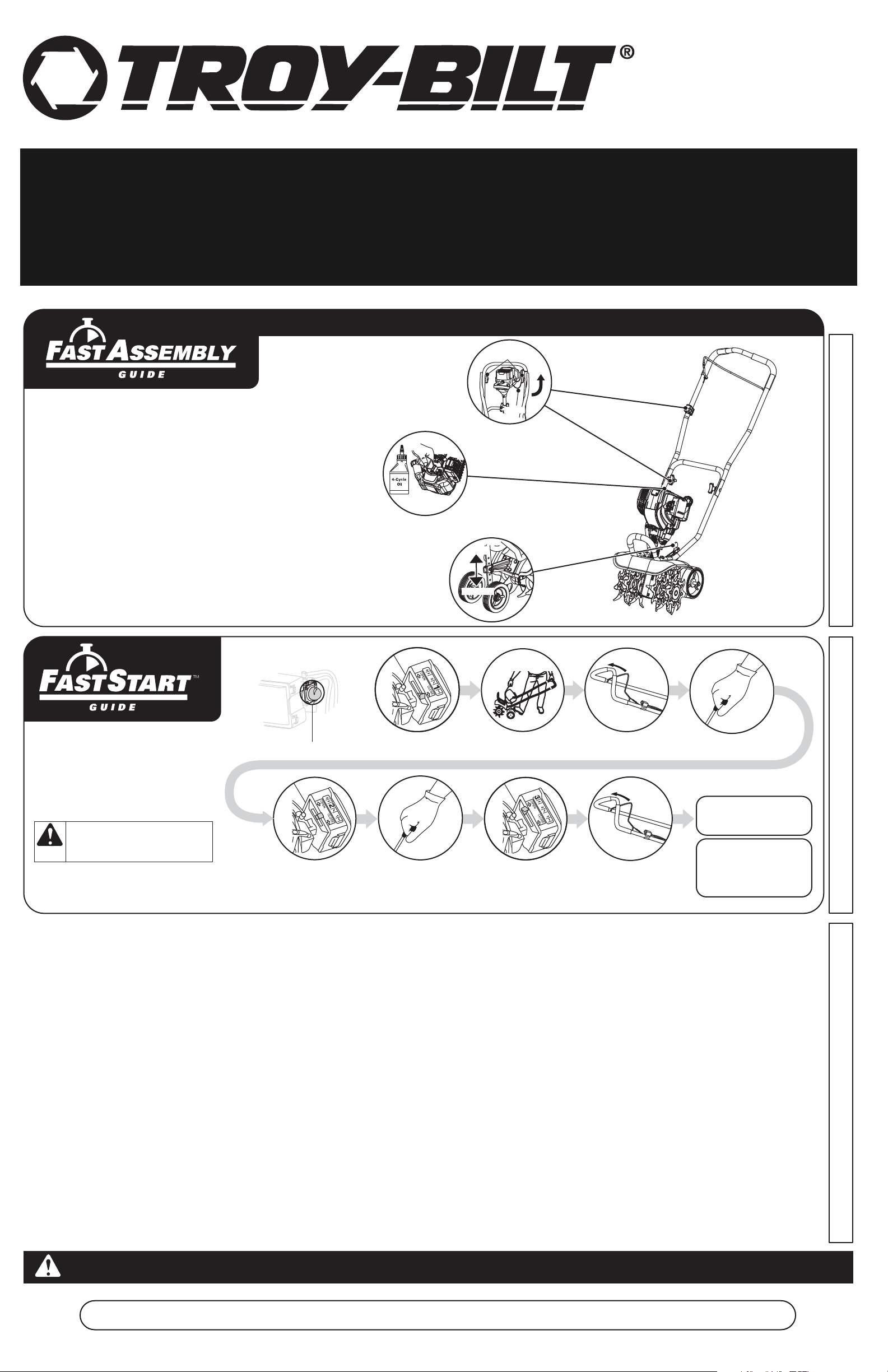
Quick Instructions to
Assemble the Unit
For complete instructions, refer to the
Assembly Instructions section of this
manual.
Loosen the handlebar knobs and swing the
handlebars up into the operating position. Taking
care not to pinch any cables or wires, tighten the
knobs to secure the handlebars. Firmly press the
ON/ OFF Control bracket into the hole on the inside
of the upper handle.
Tip the unit so that the back of the engine is
facing up in a vertical position. Remove the oil
fill plug from the crankcase and pour the entire
bottle of 4-cycle oil into the oil fill hole.
NOTE: Do not mix gas and oil
Quick Instructions
to Start the Unit
For complete instructions, refer to
Starting/ Stopping Instructions section
of this manual.
WARNING:
on START. Always stand in starting
position with foot on wheel when
starting the unit.
Tines WILL ROTATE
Remove cotter pin from the clevis pin and slide
clevis pin out of tailpiece bracket. Slide the wheel
support bracket up or down to the desired tine
depth. Place the clevis pin through the aligned holes
and secure with clevis pin and cotter pin.
Press primer bulb 10 times.
Move blue choke
lever to Position 2.
Place choke lever in
Position 1.
Pull the rope 3 to 5
times to start. Run
engine for 30-60
seconds to warm up.
Deeper
Shallower
Stand in the
starting position.
While continuing to
squeeze the throttle
control, move the blue
choke lever to Position 3.
SQUEEZE and HOLD throttle
control for ALL further steps.
Continue warming for an
additional 60 seconds.
During this time the unit
may be used.
5 X
Pull the rope
5 times.
DIDN’T START?
Repeat these instructions.
If engine still fails to start, refer
to the Starting/ Stopping
instructions section of this
manual for additional starting
and troubleshooting information.
IMPORTANT: READ OPERATOR’S MANUAL THOROUGHLY AND FOLLOW THE SAFE OPERATION PRACTICES BEFORE OPERATING THE UNIT.
Page 2
2
• SAFETY AND INTERNATIONAL SYMBOLS •
This operator's manual describes safety and international symbols and pictographs that may appear on this product.
Read the operator's manual for complete safety, assembly, operating, maintenance, and repair information.
RULES FOR SAFE OPERATION
The purpose of safety symbols is to attract attention to possible dangers. The safety symbols,
and their explanations, deserve careful attention and understanding. The safety warnings do not by
themselves eliminate any danger. The instructions or warnings they give are not substitutes for proper
accident prevention measures.
NOTE:
Advises of information or instructions vital to the operation or maintenance of the equipment.
SPARK ARRESTOR NOTE
NOTE: For users on U.S. Forest Land and in the states of California, Maine, Oregon and Washington.
All U.S. Forest Land and the state of California (Public Resources Codes 4442 and 4443), Oregon and
Washington require, by law that certain internal combustion engines operated on forest brush and/or grasscovered areas be equipped with a spark arrestor, maintained in effective working order, or the engine be
constructed, equipped and maintained for the prevention of fire. Check with your state or local authorities for
regulations pertaining to these requirements. Failure to follow these requirements could subject you to liability
or a fine. This unit is factory equipped with a spark arrestor. If it requires replacement, ask your LOCAL
SERVICE DEALER to install the Accessory Part #753-06238 Muffler Assembly.
READ ALL INSTRUCTIONS BEFORE OPERATING
• Read the instructions carefully. Be familiar with the controls and proper use of the unit.
• Do not operate this unit when tired, ill, or under the influence of alcohol, drugs, or medication.
• Children and teens under the age of 15 must not use the unit, except for teens guided by an adult.
• All guards and safety attachments must be installed properly before operating the unit.
• Inspect the unit before use. Replace damaged parts. Check for fuel leaks. Make sure all fasteners are in
place and secure. Replace parts that are cracked, chipped, or damaged in any way. Do not operate the
unit with loose or damaged parts.
• Carefully inspect the area before starting the unit. Remove all debris and hard or sharp objects such as
glass, wire, etc.
• Be aware of the risk of injury to the head, hands and feet.
• Clear the area of children, bystanders, and pets. At a minimum, keep all children, bystanders, and pets
outside a 50 feet (15 m.) radius; there still may be a risk to bystanders from thrown objects. Bystanders
should be encouraged to wear eye protection. If approached, stop the unit immediately.
• Squeeze the throttle control and check that it returns automatically to the idle position. Make all
adjustments or repairs before using unit.
SAFETY WARNINGS FOR GAS UNITS
• Store fuel only in containers specifically designed and approved for the storage of such materials.
• Avoid creating a source of ignition for spilled fuel. Do not start the engine until fuel vapors dissipate.
• Always stop the engine and allow it to cool before filling the fuel tank. Never remove the cap of the fuel
tank, or add fuel, when the engine is hot. Never operate the unit without the fuel cap securely in place.
Always loosen the fuel tank cap slowly to relieve any pressure in the tank.
• Add fuel in a clean, well-ventilated outdoor area where there are no sparks or flames. Do not smoke while
fueling. Wipe up any spilled fuel from the unit immediately. Always wipe unit dry before using.
• Move the unit at least 30 feet (9.1 m) from the fueling source and site before starting the engine. Do not
smoke or allow sparks and open flames near the area while adding fuel or operating the unit.
WHILE OPERATING
• Never start or run the unit inside a closed room or building. Breathing exhaust fumes can kill. Operate this
unit only in a well ventilated outdoor area.
• Wear safety glasses or goggles that are marked as meeting ANSI Z87.1-1989 standards. Also wear
ear/hearing protection when operating this unit. Wear a face or dust mask if the operation is dusty. Long
sleeve shirts are recommended.
• Wear heavy, long pants, boots and gloves. Do not wear loose clothing, jewelry, short pants, sandals or go
barefoot. Secure hair above shoulder level.
• This unit has a clutch. The tines remain stationary when the engine is idling. If they do not, have the unit
adjusted by an authorized service technician.
• Be sure the tines are not in contact with anything before starting the unit.
• Use the unit only in daylight or good artificial light.
• Avoid accidental starting. Be in the starting position whenever pulling the starter rope. The operator and
unit must be in a stable position while starting. See Starting/Stopping Instructions.
• Use the right tool. Only use this tool for the purpose intended.
• Use extreme caution when reversing or pulling the unit backwards.
• Do not overreach. Always keep proper footing and balance. Take extra care when working with on steep
slopes or inclines.
• Always hold the unit with both hands when operating. Keep a firm grip on the handle.
• Keep hands, face, and feet at a distance from all moving parts. Do not touch or try to stop the tines while
they are rotating.
• Do not touch the engine or muffler. These parts get extremely hot from operation. They remain hot for a
short time after turning off the unit.
• Do not operate the engine faster than the speed needed for the job. Do not run the engine at high speed
when the unit is not in use.
• Always stop the engine when work is delayed or when walking from one location to another.
• If striking or becomes entangled with a foreign object, stop the engine immediately and check for
damage. Do not operate before repairing damage. Do not operate the unit with loose or damaged parts.
• Stop and switch the engine to off for maintenance or repair.
• Use only original equipment manufacturer replacement parts and accessories for this unit. These are
available from an authorized service dealer. The use of any unauthorized parts or accessories could lead
to serious injury to the user, or damage to the unit, and void the warranty.
• Keep unit clean of vegetation and other materials that may become lodged or entangled in the unit.
• To reduce fire hazard, keep the engine and muffler free from grass, leaves, excessive grease or carbon
build up.
After use
• Clean the unit with household cleaner to remove any gum buildup. Oil the tines with machine oil to
prevent rust.
OTHER SAFETY WARNINGS
• Never store a fueled unit inside a building where fumes may reach an open flame or spark.
• Allow the engine to cool before storing or transporting. Be sure to secure the unit while transporting.
• Store the unit in a dry area, locked up or up high to prevent unauthorized use or damage. Keep out of the
reach of children.
• Never douse or squirt the unit with water or any other liquid. Keep handles dry, clean and free from
debris. Clean after each use. See the Cleaning and Storage instructions.
• Keep these instructions. Refer to them often and use them to instruct other users. If loaning someone this
unit, also loan them these instructions.
SAVE THESE INSTRUCTIONS
• IMPORTANT SAFETY INSTRUCTIONS •
SERVICE INFORMATION
TABLE OF CONTENTS
Service Information . . . . . . . . . . . . . . . . . . . . . . . . . . . . . . . . . . . . . . . . . . . . . . . . . . . . . . . . . . . . . . . .2
Rules for Safe Operation . . . . . . . . . . . . . . . . . . . . . . . . . . . . . . . . . . . . . . . . . . . . . . . . . . . . . . . . . . .2
Know Your Unit . . . . . . . . . . . . . . . . . . . . . . . . . . . . . . . . . . . . . . . . . . . . . . . . . . . . . . . . . . . . . . . . . . .3
Assembly Instructions . . . . . . . . . . . . . . . . . . . . . . . . . . . . . . . . . . . . . . . . . . . . . . . . . . . . . . . . . . . . .3
Oil and Fuel Information . . . . . . . . . . . . . . . . . . . . . . . . . . . . . . . . . . . . . . . . . . . . . . . . . . . . . . . . . . . .3
Starting/Stopping Instructions . . . . . . . . . . . . . . . . . . . . . . . . . . . . . . . . . . . . . . . . . . . . . . . . . . . . . . .3
Operating Instructions . . . . . . . . . . . . . . . . . . . . . . . . . . . . . . . . . . . . . . . . . . . . . . . . . . . . . . . . . . . . .3
Maintenance & Repair Instructions . . . . . . . . . . . . . . . . . . . . . . . . . . . . . . . . . . . . . . . . . . . . . . . . . . .4
Cleaning and Storage . . . . . . . . . . . . . . . . . . . . . . . . . . . . . . . . . . . . . . . . . . . . . . . . . . . . . . . . . . . . . .4
Troubleshooting Chart . . . . . . . . . . . . . . . . . . . . . . . . . . . . . . . . . . . . . . . . . . . . . . . . . . . . . . . . . . . . .5
Specifications . . . . . . . . . . . . . . . . . . . . . . . . . . . . . . . . . . . . . . . . . . . . . . . . . . . . . . . . . . . . . . . . . . . .5
Warranty Information . . . . . . . . . . . . . . . . . . . . . . . . . . . . . . . . . . . . . . . . . . . . . . . . . . . . . . . . . . . . .16
All information, illustrations, and specifications in this manual are based on the latest product information
available at the time of printing. We reserve the right to make changes at any time without notice.
Copyright© 2009 MTD SOUTHWEST INC, All Rights Reserved.
For service call 1-800-828-5500 in the United States or 1-800-668-1238 in Canada to obtain a list of authorized
service dealers near you. For more details about your unit, visit our website at www.troybilt.com or
www.troybilt.ca.
If you have difficulty assembling this product or have any questions regarding the controls, operation or
maintenance of this unit, please call the Customer Support Department.
DO NOT RETURN THE UNIT TO THE RETAILER. PROOF OF PURCHASE WILL BE REQUIRED FOR
WARRANTY SERVICE.
THIS PRODUCT IS COVERED BY ONE OR MORE U.S. PATENTS. OTHER PATENTS PENDING.
Service on this unit both within and after the warranty period should be performed only by an authorized and
approved service dealer.
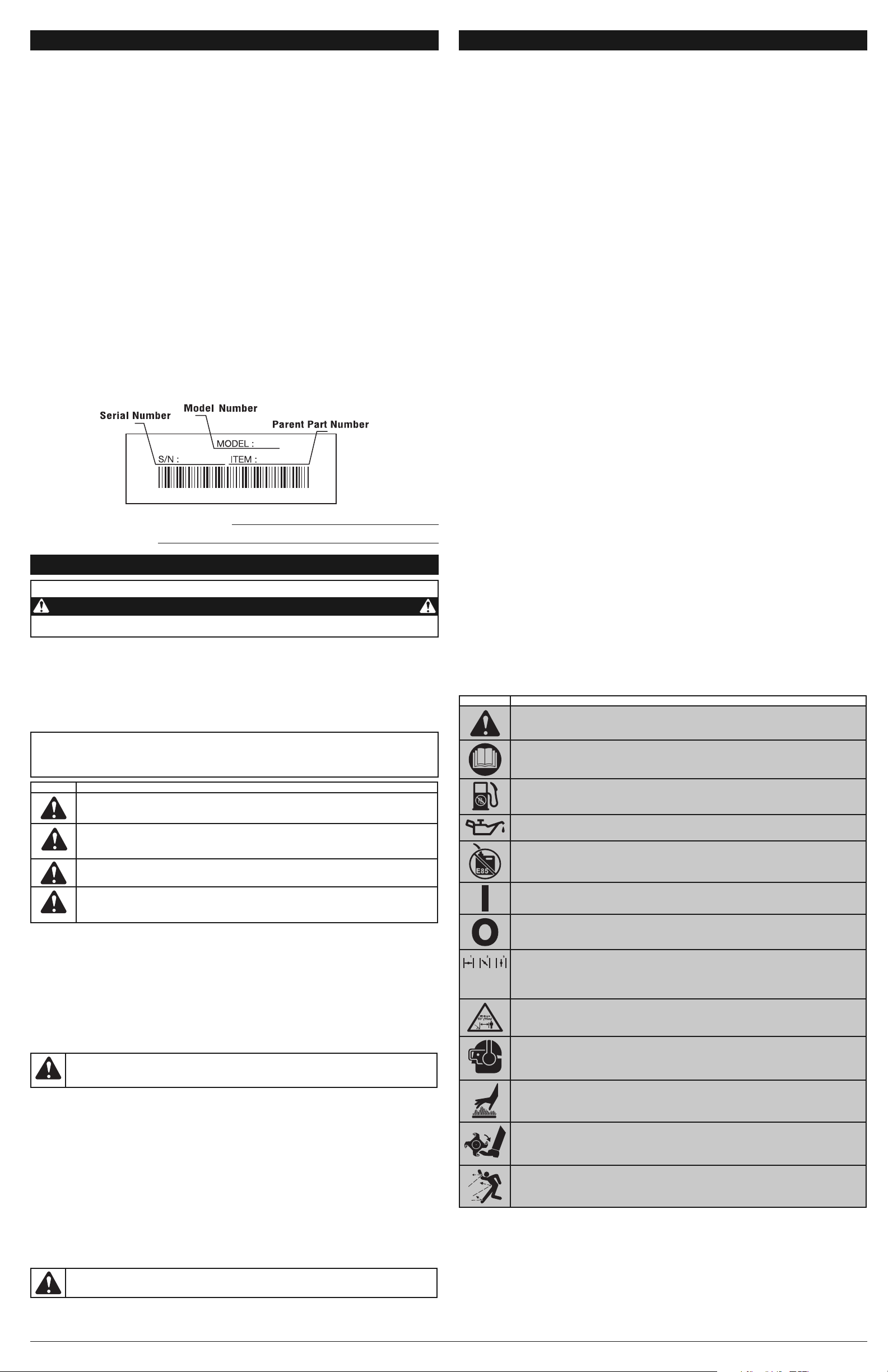
Before beginning, locate the unit’s model plate. It lists the model and serial numbers of your unit. Refer to
the sample plate below and copy the information for future reference.
Copy the serial number here:
Copy the model and parent part numbers here:
CALIFORNIA PROPOSITION 65 WARNING
WARNING
THE ENGINE EXHAUST FROM THIS PRODUCT CONTAINS CHEMICALS KNOWN TO THE STATE
OF CALIFORNIA TO CAUSE CANCER, BIRTH DEFECTS OR OTHER REPRODUCTIVE HARM.
WARNING:
When using the unit, all safety rules must be followed. Please read these
instructions before operating the unit in order to ensure the safety of the operator and any
bystanders. Please keep these instructions for later use.
WARNING:
Gasoline is highly flammable, and its vapors can explode if ignited. Take the
following precautions:
RULES FOR SAFE OPERATION
SYMBOL MEANING
• SAFETY ALERT SYMBOL
Indicates danger, warning or caution. May be used in conjunction with other symbols
or pictographs.
• READ OPERATOR'S MANUAL
WARNING: Read the operator’s manual(s) and follow all warnings and safety
instructions. Failure to do so can result in serious injury to the operator and/or bystanders.
• UNLEADED FUEL
Always use clean, fresh unleaded fuel
• OIL
Refer to operator’s manual for the proper type of oil.
• DO NOT USE E85 FUEL IN THIS UNIT
WARNING: It has been proven that fuel containing greater than 15% ethanol will
likely damage this engine and void the warranty.
• ON/OFF STOP CONTROL
ON / START / RUN
• ON/OFF STOP CONTROL
OFF or STOP
• CHOKE CONTROL
1. • FULL choke position
2. • PARTIAL choke position
3. • RUN choke position
• KEEP BYSTANDERS AWAY
WARNING: Keep all bystanders, especially children and pets, at least 50 feet (15
m.) from the operating area.
• WEAR EYE AND HEARING PROTECTION
WARNING: Thrown objects and loud noise can cause severe eye injury and hearing
loss. Wear eye protection meeting ANSI Z87.1-1989 standards and ear protection
when operating this unit. Use a full face shield when needed.
• HOT SURFACE
WARNING: Do not touch a hot engine. These parts get extremely hot from
operation and may cause severe burns. When the unit is turned off the engine will
remain hot for a short time.
• GARDEN CULTIVATORS – ROTATING TINES CAN CAUSE SEVERE INJURY
WARNING: Stop the engine and allow the tines to stop before installing or
removing tines, or before cleaning or performing any maintenance. Keep hands and
feet away from rotating tines.
• THROWN OBJECTS AND ROTATING CUTTER CAN CAUSE SEVERE INJURY
WARNING: Small objects can be propelled at high speed, causing injury. Keep
away from the rotating rotor.
NOTE- This Unit Can Use an Electric Start or Power Start Bit™ Optional Accessory!
Please refer to the Electric Starter or Power Start Bit™ operator’s manual for proper use of
these features. (Items Sold Separately! Please refer to page 5 of this manual for more
information about purchasing these accessories.)
READ THE OPERATOR’S MANUAL AND FOLLOW ALL WARNINGS AND SAFETY
INSTRUCTIONS. FAILURE TO DO SO CAN RESULT IN SERIOUS INJURY TO THE OPERATOR
AND/OR BYSTANDERS.
FOR QUESTIONS, CALL 1-800-828-5500 IN U.S. OR 1-800-668-1238 IN CANADA
SYMBOL MEANING
WARNING:
Failure to obey a safety warning can result in injury to yourself and others.
Always follow the safety precautions to reduce the risk of fire, electric shock and personal injury.
CAUTION:
Failure to obey a safety warning may result in property damage or personal
injury to yourself or to others. Always follow the safety precautions to reduce the risk of fire,
electric shock and personal injury.
SAFETY ALERT:
Indicates danger, warning or caution. Attention is required in order to
avoid serious personal injury. May be used in conjunction with other symbols or pictographs.
DANGER:
Failure to obey a safety warning will result in serious injury to yourself or to
others. Always follow the safety precautions to reduce the risk of fire, electric shock and
personal injury.
Page 3
STARTING INSTRUCTIONS
1. Fill the fuel tank with fresh, clean unleaded gasoline. Refer to Fueling the Unit.
NOTE: There is no need to turn the unit on. The On/Off Control is in the ON ( I )
position at all times (Fig. 9).
2. Fully press and release the primer bulb 10 times, slowly. Some amount of fuel
should be visible in the primer bulb and fuel lines (Fig. 10). If fuel can not be seen
in the bulb, press and release the bulb until fuel is visible.
3. Place the choke lever in Position 1 (Fig. 10).
NOTE: Make sure to always have the unit tilted back slightly to bring the tines off
the ground when starting.
4. Hold the handlebar and squeeze the throttle contol with one hand and grab the
starter rope with the other hand. Using one foot to hold down the cultivator (Fig. 11).
Pull the starter rope 5 times.
5. Place the choke lever in Position 2 (Fig. 10)
6. Squeeze the throttle control, pull the starter rope in a controlled motion 3 to 5
times to start the engine.
7. Keep the throttle squeezed and allow the engine to warm up for 30 to 60 seconds.
8. Continue squeezing the throttle control, move the choke lever to Position 3 (Fig. 10)
and continue warming the engine for an additional 60 seconds. The unit may be
used during this time.
NOTE: Unit is properly warmed up when engine accelerates without hesitation.
IF... the engine hesitates, return the choke lever to Position 2 (Fig. 10) and continue warm-up.
IF... the engine does not start, go back to step 3.
IF... the engine fails to start after a few attempts, place the choke lever in Position 3 and squeeze the throttle control.
Pull the starter rope out with a controlled and steady motion 3 to 8 times. The engine should start. If not, repeat.
IF WARM... If the engine is already warm, start the unit with the choke lever in Position 2. After the unit starts, move
the choke lever to Position 3.
FUELING THE UNIT
1. Remove the fuel cap (Fig. 7).
2. Place the gas container’s spout into the fill hole
on the fuel tank (Fig. 8) and fill the tank.
NOTE: Do not overfill the tank.
3. Wipe up any gasoline that may have spilled.
4. Reinstall the fuel cap.
5. Move the unit at least 30 ft. (9.1 m) from the
fueling source and site before starting the
engine.
NOTE: Dispose of the old gasoline in accordance to Federal, State and Local regulations.
OPERATING INSTRUCTIONS
OPERATING TIPS
1. Move the cultivator to the work area prior to starting the engine. Transport the cultivator by pushing or pulling it
along on its wheels.
2. Start the unit by following the Starting Instructions.
3. With the engine running and the tines off the ground, depress the throttle control
to increase the engine speed.
4. While holding the upper handle with both hands, slowly lower the cultivator until
the tines make contact with the ground (Fig. 12).
5. As cultivating action begins, tilt the cultivator up slightly using the handle so that the tines can penetrate the
ground.
6. Once the ground has been broken, continue at a moderate pace.
7. If the tines are digging too deep or not deep enough, adjust the wheel bracket as described in Adjusting Tine
Depth.
TRANSPORTING THE UNIT
1. Stop the engine.
2. Tilt the unit back until the tines clear the ground.
3. Push or pull the unit to the next location to be
cultivated.
WARNING:
Dress properly to reduce the risk of injury when operating this unit. Do not wear loose
clothing or jewelry. Wear eye and ear/hearing protection. Wear heavy long pants, boots and gloves. Do
not wear short pants, sandals or operate barefoot.
RECOMMENDED OIL TYPE
Using the proper type and weight of oil in the crankcase is extremely important. Check the oil before each use and
change the oil regularly. Failure to use the correct oil, or using dirty oil, can cause premature engine wear and failure.
Use a high-quality SAE 30 weight oil of API (American Petroleum Institute) service class SF, SG, SH.
ADDING OIL TO CRANKCASE: INITIAL USE
NOTE: This unit is shipped without oil. In order
to avoid damage to the unit, put oil in
the crankcase before attempting to
start the unit.
The unit is supplied with one 3.04 fluid oz. (90 ml.)
bottle of SAE 30 SF, SG, SH oil (Fig. 4).
NOTE: Save the bottle of oil. It can be used to
measure the correct amount during
future oil changes. See Changing the Oil.
1. Unscrew the top of the bottle of oil and remove the paper seal covering the
opening. Replace the top. Next, cut the tip off the funnel spout (Fig. 4).
2. Tip the unit so that the back of the engine is facing up in a vertical position.
3. Remove the oil fill plug from the crankcase (Fig. 6).
4. Pour the entire bottle of oil into the oil fill hole (Fig. 5).
NOTE: Never add oil to the fuel or fuel tank.
5. Wipe up any oil that may have spilled and reinstall the oil fill plug.
Check oil before each use and change as needed. Refer to Checking the Oil Level.
RECOMMENDED FUEL TYPE
Old fuel is the primary reason for improper unit performance. Be sure to use fresh, clean, unleaded gasoline.
NOTE: This is a four cycle engine. In order to avoid damage to the unit, do not mix oil with gasoline.
Definition of Blended Fuels
Today's fuels are often a blend of gasoline and oxygenates such as ethanol, methanol or MTBE (ether). Alcoholblended fuel absorbs water. As little as 1% water in the fuel can make fuel and oil separate or form acids when stored.
Use fresh fuel (less than 60 days old), when using alcohol-blended fuel.
Using Blended Fuels
If choosing to use a blended fuel, or its use is unavoidable, follow recommended precautions:
• Always use fresh unleaded gasoline
• Use the fuel additive STA-BIL® or an equivalent
• Drain tank and run the engine dry before storing unit
Using Fuel Additives
The use of fuel additives, such as STA-BIL® Gas Stabilizer or an equivalent, will inhibit corrosion and minimize the
formation of gum deposits. Using a fuel additive can keep fuel from forming harmful deposits in the carburetor for up
to six (6) months. Add 0.8 oz. (23 ml.) of fuel additive per gallon of fuel according to the instructions on the container.
NEVER add fuel additives directly to the unit's gas tank.
3
OIL AND FUEL INFORMATION
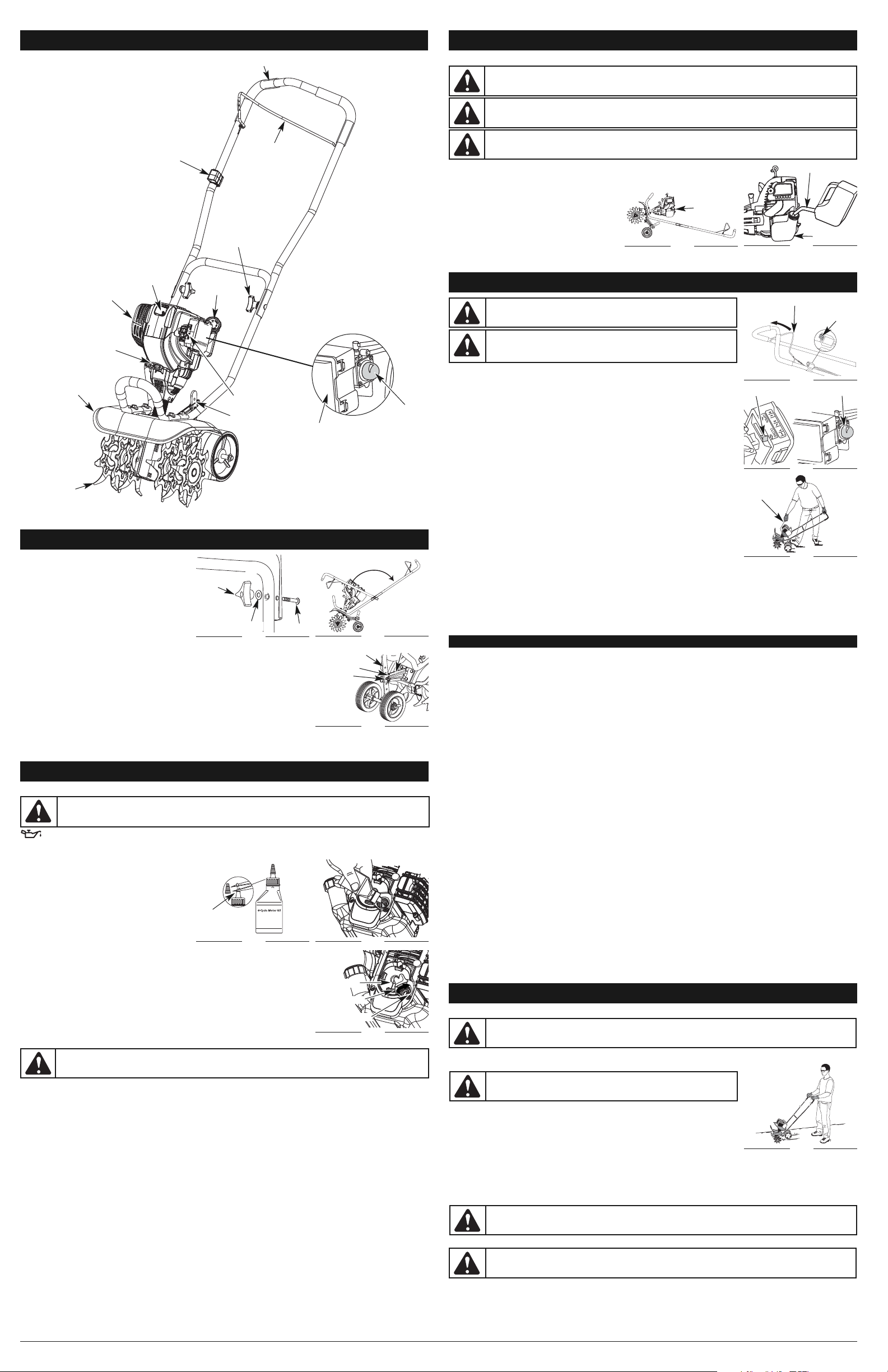
POSITIONING THE HANDLEBARS
1. Loosen the two knobs on the inside of the
handlebars (Fig. 1).
2. With the unit upright, swing the handlebars up
into the operating position (Fig. 2).
NOTE: Take care not to pinch the throttle cable
or switch wires when positioning the
handlebar.
3. Tighten the knobs to secure the handlebars in
place.
NOTE: Do not over-tighten the knobs.
4. Reconnect the spark plug wire to the spark plug.
ADJUSTING TINE DEPTH
To adjust the wheel support bracket proceed as follows:
1. Stop engine and disconnect spark plug to avoid accidental starting.
2. Remove clip from the cotter pin and slide clevis pin out of tailpiece bracket (Fig. 3).
3. Slide the wheel support bracket up or down in the tailpiece, aligning the holes to
the desired tine depth.
4. Place the cotter pin through the hole and secure with clip.
ASSEMBLY INSTRUCTIONS
STARTING/STOPPING INSTRUCTIONS
WARNING:
Avoid accidental starting. Make sure to be in the starting
position when pulling the starter rope (Fig. 11). To avoid serious injury,
the operator and unit must be in a stable position while starting.
ON/ OFF
Control
Throttle Control
Fig. 9
Starter
Rope
Fig. 11
Fig. 10
Primer Bulb
Choke Lever
WARNING:
It has been proven that fuel containing greater than 15% ethanol will likely damage this engine
and void the warranty.
WARNING:
Tines WILL ROTATE when STARTING. Always stand
in starting position with foot on wheel when starting the unit.
WARNING:
To prevent serious personal injury, never pick-up or
carry the unit while the engine is running.
Fig. 12
KNOW THE UNIT
APPLICATIONS
• Cultivating sod and light to medium soil
• Cultivating in garden areas, around trees, etc.
• Edging
Throttle Control
Handlebar
Spark Plug
Tine Guard
Starter Rope Grip
Cultivator
Tines
Muffler
On/Off Control
Handlebar Knob
Fuel Cap
Choke Lever
HOW TO START THE UNIT USING THE ELECTRIC STARTER OR POWER START BIT ACCESSORY.
NOTE- This Unit Can Use an Electric Start or Power Start Bit™ Optional Accessory!
Please refer to the Electric Starter or Power Start Bit operator’s manual for proper use of this feature. (Items
Sold Separately! Please refer to page 5 of this manual about purchasing these accessories.)
STARTING INSTRUCTIONS
1. Fill the fuel tank with fresh, clean unleaded petrol. Refer to Fueling the Unit.
NOTE: There is no need to turn the unit on. The On/Off Control is in the ON ( I ) position at all times (Fig. 9).
2. Fully press and release the primer bulb 10 times, slowly. Some amount of fuel should be visible in the primer bulb
(Fig. 10). If fuel cannot be seen in the bulb, press and release the bulb until fuel is visible.
3. Move the choke lever to Position 1 (Fig. 10).
NOTE: Make sure to always have the unit tilted back slightly to bring the tines off the ground when starting.
4. Hold the handlebar and squeeze the throttle control with one hand and place the electric starter or Power Start
Bit™ into the back of the unit. Refer to the Operation Section of the electric starter or Power Start Bit™ operator’s
manual.
5. Press and hold the electric starter or drill ON (I) button for 2 seconds.
6. Move the choke lever to Position 2 (Fig. 10).
7. Squeeze the throttle control lever, press and hold the electric starter or drill ON (I) button for 2-second intervals until
the unit starts.
8. Continue to squeeze the throttle control, remove the electric starter or drill from the unit and allow the engine to
warm up for 30 to 60 seconds.
9. Continue squeezing the throttle control, move the choke lever to Position 3 (Fig. 10) and run the unit for an
additional 60 seconds. The unit may be used during this time.
NOTE: Unit is properly warmed up when engine accelerates without hesitation.
IF... the engine hesitates, return the choke lever to Position 2 (Fig. 10) and continue warm-up.
IF... the engine does not start, go back to step 3.
IF... the engine fails to start after a few attempts, place the choke lever in Position 3 and squeeze the throttle
control. Press and hold the electric starter or drill ON (I) button for 2-second intervals until the unit starts.
IF WARM... If the engine is already warm, start the unit with the blue choker lever in Position 2. After the unit starts,
move the blue choker lever to Position 3.
STOPPING INSTRUCTIONS
1. Release the throttle control and allow the engine to cool down by idling.
2. Press the On/Off Control switch to the OFF (O) position (Fig. 9).
IF USING THE OPTIONAL ELECTRIC STARTER OR POWER START BIT™ ACCESSORY
OIL AND FUEL INFORMATION
WARNING:
OVERFILLING OIL CRANKCASE MAY CAUSE SERIOUS PERSONAL INJURY. Check and
maintain the proper oil level in the crank case; it is important and cannot be overemphasized. Check the
oil before each use and change it as needed. See Changing the Oil.
Handlebar
Knob
Washer
Bolt
Fig. 1
Wheel Support
Bracket
Wheel Bracket
Fig. 3
Fig. 2
Clevis Pin
Cotter Pin
WARNING:
Gasoline is extremely flammable. Ignited vapors may explode. Always stop the engine
and allow it to cool before filling the fuel tank. Do not smoke while filling the tank. Keep sparks and open
flames at a distance from the area.
WARNING:
Remove fuel cap slowly to avoid injury from fuel spray. Never operate the unit without the
fuel cap securely in place.
WARNING:
Add fuel in a clean, level and well ventilated outdoor area. Wipe up any spilled fuel immediately.
Avoid creating a source of ignition for spilled fuel. Do not start the engine until fuel vapors dissipate.
Funnel
Spout
Fig. 4
Fig. 5
Oil Plug
O-Ring
Oil Fill Hole
Fig. 6
Fuel Cap
Fig. 7
Fig. 8
Gas Can Spout
Fuel Tank
WARNING:
To prevent serious personal injury, use extreme caution when reversing or pulling the unit
backwards.
WARNING:
To prevent serious personal injury, always stop the engine when operation is delayed or
when transporting the unit from one location to another.
Primer Bulb
Air Filter
Cover
Wheel Support
Bracket
Page 4

4
MAINTENANCE AND REPAIR INSTRUCTIONS
MAINTENANCE SCHEDULE
Perform these required maintenance procedures at the frequency stated in the table. These procedures should also be
a part of any seasonal tune-up.
NOTE: Some maintenance procedures may require special tools or skills. If unsure about these procedures take the
unit to any non-road engine repair establishment, individual or authorized service dealer.
NOTE: Maintenance, replacement, or repair of the emission control devices and system may be performed by any
non-road engine repair establishment, individual or authorized service dealer.
WARNING:
To prevent serious injury, never perform maintenance or repairs with unit running. Always
service and repair a cool unit. Disconnect the spark plug wire to ensure that the unit cannot start.
TINE REMOVAL AND REPLACEMENT
All tines should be replaced at the same time as they will wear evenly through normal use. Work on one side at a time.
1. Make sure the unit is off.
NOTE: It may be necessary to lay the cultivator back in a horizontal position on a flat level surface with the upper
handle touching the ground. It may also be necessary to wash any dirt off the tines and shaft for ease of
removal.
2. Remove the clip from the cotter pin that is
between the 2 outer tines (Fig. 14)
3. Remove the cotter pin and slide the tines off of
the shaft (Fig. 13).
4. Clean and oil the shaft.
5. Slide on the new tines with the hubs facing
each other (Fig. 13).
NOTE: Make sure the single tine goes on the
tine shaft first with the double tines on
the outside and holes on the outer tines are aligned with the outer hole on the shaft (Fig. 13).
6. Secure the new tines to the shaft by sliding the cotter pin into the holes between the 2 outer tines (Fig. 14)
7. Insert the clip into the cotter pin to secure the tines.
8. Repeat step 2 through 7 for the opposite side.
CHECKING THE OIL LEVEL
The importance of checking and maintaining the
proper oil level in the crankcase cannot be
overemphasized. Check oil before each use:
1. Stop the engine and allow oil to drain into the
crankcase.
2. Place the unit in a horizontal position to get a
proper oil level reading (Fig. 15).
3. Keep dirt, grass clippings and other debris out
of the engine. Clean the area around the
dipstick before removing it.
4. Remove the oil fill plug.
5. Look into the oil fill hole, use a flashlight if needed. The oil should be just touching the inner most thread (Fig. 16).
6. If the oil level is not touching the inner most thread on the oil fill hole, add a small amount of oil to the oil fill hole
and recheck (Fig. 16). Repeat this procedure until the oil level reaches the inner most thread on the oil fill hole.
NOTE: Do not overfill the unit.
NOTE: Make sure the O-ring is in place on the oil fill plug when checking and changing the oil (Fig. 17).
CHANGING THE OIL
For a new engine, change the oil after the first 10
hours of operation. Change the oil while the engine
is still warm. The oil will flow freely and carry away
more impurities.
1. Unplug spark plug boot to prevent accidental
starting.
2. Remove the oil fill plug (Fig. 17).
3. Pour the oil out of the oil fill hole and into a
container by tipping the unit to a vertical
position (Fig. 18). Allow ample time for
complete drainage.
4. Wipe up any oil residue on the unit and clean up any oil that may have spilled.
Dispose of the oil according to Federal, State and local regulations.
5. Refill the crankcase with 3.04 fluid ounce (90 ml) of SAE 30 SF, SG, SH oil.
NOTE: Use the bottle and spout saved from initial use to measure the correct
amount of oil. The top of the label on the bottle measures approximately
3.04 ounces (90 ml) (Fig. 19). Check the level, See Checking the Oil Level.
If the level is low, add a small amount of oil and recheck. Do not overfill
(Fig. 16).
6. Replace the oil fill plug.
7. Reconnect the spark plug boot.
AIR FILTER MAINTENANCE
Cleaning the Air Filter
Clean and re-oil the air filter every 10 hours of
operation. It is an important item to maintain.
Failure to maintain the air filter properly can result
in poor performance or can cause permanent
damage to the engine.
1. Open the air filter cover. Push the tab on the
under side of the cover inward. Then pull the air
filter cover out and up. (Fig. 20).
2. Remove the air filter (Fig. 20).
3. Wash the filter in detergent and water (Fig. 21).
Rinse the filter thoroughly and allow it to dry.
4. Apply enough clean SAE 30 motor oil to lightly
coat the filter (Fig. 22).
5. Squeeze the filter to spread and remove excess
oil (Fig. 23).
6. Replace the filter (Fig. 20).
NOTE: Operating the unit without the air filter,
will VOID the warranty.
7. Reinstall the air filter cover. Position the slots on
the top of the air filter cover onto the tabs at the top of the back plate (Fig. 20).
8. Swing the cover down until the tab on the air filter backplate snaps into place in the slot on the air filter cover (Fig. 20).
CARBURETOR ADJUSTMENT
The idle speed of the engine is adjustable. An idle adjustment screw is between the air filter cover and the engine
starter housing (Fig. 24).
NOTE: Careless adjustments can seriously damage the unit. An authorized service dealer should make carburetor
adjustments.
Check Fuel
Old fuel is usually the reason for improper unit performance. Drain and refill the tank with fresh fuel prior to making any
adjustments. Refer to Oil and Fuel Information.
Clean Air Filter
The condition of the air filter is important to the operation of the unit. A dirty air filter will restrict air flow. This is often
mistaken for an out of adjustment carburetor. Check the condition of the air filter before adjusting the idle speed screw.
Refer to Air Filter Maintenance.
Cotter Pin
Fig. 14
ADJUST IDLE SPEED SCREW
If, after checking the fuel and cleaning the air filter, the engine still will not idle, adjust
the idle speed screw as follows:
1. Start the engine and let it run at a high idle for a minute to warm up. Refer to
Starting/Stopping Instructions.
2. Release the throttle trigger and let the engine idle. If the engine stops, insert a
small phillips in between the Air Filter Cover and the Engine Cover (Fig. 24). Turn
the idle speed screw in, clockwise, 1/8 of a turn at a time (as needed) until the
engine idles smoothly.
NOTE: The tines should not rotate when the engine idles.
3. If the tines rotates when the engine idles, turn the idle speed screw
counterclockwise 1/8 of a turn at a time (as needed), to reduce idle speed.
Checking the fuel, cleaning the air filter, and adjusting the idle speed should solve most engine problems. If not and all
of the following are true:
• the engine will not idle
• the engine hesitates or stalls on acceleration
• there is a loss of engine power
Have the carburetor adjusted by an authorized service dealer.
ROCKER ARM CLEARANCE
This requires disassembly of the engine. If unsure or unqualified to perform this task, take the unit to an authorized
service center.
NOTE: Inspect the valve to rocker arm
clearance with a feeler gauge after the
first 10 hours of operation and every 25
hours of operation.
• The engine must be cold when checking or
adjusting the valve clearance.
• This task should be performed inside, in a
clean, dust free area.
1. Remove the six (6) screws on the back of the
engine cover with a Flat-head or T-25 Torx
screwdriver (Fig. 25).
2. Disconnect the spark plug wire.
3. Clean dirt from around the spark plug. Remove
the spark plug from the cylinder head by
turning a 5/8 in. socket counterclockwise.
4. Remove the engine cover (Fig. 25).
5. Clean dirt from around the rocker arm cover.
Remove the screw holding the rocker arm
cover with a large flat blade screwdriver or Torx
T-25 bit (Fig. 26). Remove the rocker arm cover and gasket.
6. Pull the starter rope slowly to bring the piston to the top of its travel, (known as top dead center). Check that:
• The piston is at the top of its travel while looking in the spark plug hole (Fig. 26).
• Both rocker arms move freely, and both valves are closed.
If these statements are not true, repeat this step.
7. Slide the feeler gauge between the rocker arm and the valve return spring. Measure the clearance between the
valve stem and rocker arm (Fig. 27). Measure both the intake and exhaust valves.
The recommended clearance for both intake and exhaust is .003 – .006 in. (.076 – 0.152 mm). Use a standard
automotive .005 in. (0.127 mm) feeler gauge. The feeler gauge should slide between the rocker arm and valve stem
with a slight amount of resistance, without binding. See Figures 27 and 28.
8. If the clearance is not within specification:
a. Turn the adjusting nut using a 5/16 inch (8 mm) wrench or nut driver (Fig. 28).
• To increase clearance, turn the adjusting nut counterclockwise.
• To decrease clearance, turn the adjusting nut clockwise.
b. Recheck both clearances, and adjust as necessary.
9. Reinstall the rocker arm cover using a new gasket. Torque the screw to 20–30 in•lb (2.2–3.4 N•m).
10. Check the spark plug and reinstall. See Replacing the Spark Plug.
11. Replace the spark plug wire.
12. Reinstall the engine cover. Check alignment of the cover before tightening the screws. Tighten screws.
REPLACING THE SPARK PLUG
Use a replacement part 769-05255 or a Champion® ref. #RDZ19H spark plug. The correct air gap is 0.025 in. (0.635
mm.). Remove the plug after every 25 hours of operation and check its condition.
1. Stop the engine and allow it to cool. Remove the six (6) screws on the back of the engine cover with a Flat-head or
T-25 Torx screwdriver (Fig. 25).
2. Grasp the plug wire firmly and pull the cap from the spark plug.
3. Clean dirt from around the spark plug. Remove the spark plug from the cylinder
head by turning a 5/8 in. socket counterclockwise.
4. Replace cracked, fouled or dirty spark plug. Set the air gap at 0.025 in. (0.635 mm)
using a feeler gauge (Fig. 29).
5. Install a correctly-gapped spark plug in the cylinder head. Turn the 5/8 in. socket clockwise until snug.
If using a torque wrench torque to: 110-120 in.•lb. (12.3-13.5 N•m)
Do not over tighten.
SPARK ARRESTOR MAINTENANCE
1. Remove the rear engine cover. See Rocker Arm Clearance.
2. With a flat blade screwdriver or Torx T-20 bit and a T-25 bit, remove the screws
attaching the spark arrestor cover to the muffler (Fig. 30).
3. Pull the tab on the spark arrestor cover out of the muffler. Remove the spark
arrestor cover.
4. Remove the spark arrestor screen from the spark arrestor cover.
5. Clean the spark arrestor screen with a wire brush or replace it.
6. Reinstall the spark arrestor screen, spark arrestor cover and screws.
CLEANING
Use a small brush to clean off the outside of the unit. Do not use strong detergents. Household cleaners that contain
aromatic oils such as pine and lemon, and solvents such as kerosene, can damage plastic housing or handle. Wipe off
any moisture with a soft cloth.
STORAGE
• Never store the unit with fuel in the tank where fumes may reach an open flame or spark.
• Allow the engine to cool before storing.
• Lock up the unit to prevent unauthorized use or damage.
• Store the unit in a dry, well-ventilated area.
• Store the unit out of the reach of children.
LONG TERM STORAGE
1. Drain all gasoline from the gas tank into a container. Do not use gas that has been stored for more than 60 days.
Dispose of the old gasoline in accordance to Federal, State, and Local regulations.
2. Start the engine and allow it to run until it stalls. This ensures that all gasoline has been drained from the carburetor.
3. Allow the engine to cool. Remove the spark plug and put 5 drops of high quality motor oil into the cylinder. Pull the
starter rope slowly to distribute the oil. Reinstall the spark plug.
NOTE: Remove the spark plug and drain all of the oil from the cylinder before attempting to start the unit after
storage.
4. Change the oil, referring to Changing the Oil. Dispose of the old oil in accordance to Federal, State and Local
regulations.
5. Thoroughly clean the unit and inspect for any loose or damaged parts. Repair or replace damaged parts and
tighten loose screws, nuts or bolts. The unit is ready for storage.
TRANSPORTING
• Allow the engine to cool before transporting.
• Secure the unit while transporting.
• Drain the gas tank before transporting.
• Tighten gas cap before transporting
WARNING:
To prevent extensive engine wear and damage to the unit, always maintain the proper oil
level in the crankcase. Never operate the unit with a low oil level.
WARNING: Do not sand blast, scrape or clean electrodes. Grit in the
engine could damage the cylinder.
Fig. 29
0.025 in.
(0.635 mm.)
WARNING:
To prevent serious personal injury, always wear heavy gloves when handling the tines.
Fig. 23
Fig. 21
Fig. 20
Fig. 22
Air Filter Cover
Air Filter
Slot
Outer
Tines
Hubs
Inner
Tine
Fig. 13
Fig. 25
Spark
Plug
Hole
Fig. 26
Rocker
Arm Cover
Feeler
Gauge
Fig. 27
Intake
Exhaust
Fig. 28
0.003 - 0.006 in.
(0.076 -0.152mm)
Adjustment Nut
Valv e
MAINTENANCE AND REPAIR INSTRUCTIONS
WARNING:
To avoid serious personal injury, always turn the unit off and allow it to cool before
cleaning or servicing it.
FREQUENCY MAINTENANCE REQUIRED SEE
Before starting engine
Fill fuel tank with fresh fuel
Check oil
p. 3
p. 4
Every 10 hours Clean and re-oil air filter p. 5
1st change at 10 hours
Every 25 hours after
Change oil
Clean spark arrestor
p. 4
p. 4
10 hours on new engine
Every 25 hours
Check rocker arm to valve clearance and adjust
Check spark plug condition and gap
p. 4
p. 4
WARNING:
To avoid serious personal injury, always turn the unit off and allow it to cool before
cleaning or servicing it.
WARNING:
To avoid serious personal injury, always turn the unit off and allow it to cool before
cleaning or servicing it.
WARNING:
The tines may spin during idle speed adjustments. Wear protective clothing and observe
all safety instructions to prevent serious personal injury.
Fig. 18
Fig. 16
Fig. 15
Oil Full Line
Fig. 19
1
23
Fig. 24
Idle Adjustment Screw
WARNING:
To avoid serious personal injury, always turn the unit off and allow it to cool before
cleaning or servicing it.
Fig. 30
Muffler
Clip
Tine
Shaft
Align Holes
Oil Plug
O-Ring
Oil Fill Hole
Fig. 17
Oil Bottle Fill Line
Hooks
Tab
Rocker
Arm
Screws
Screws
Screws
Spark Arrestor
Screen
Cover
T-25
Screw
T-20 Screw
Slot
Page 5
CAUSE ACTION
Old fuel Drain gas tank and add fresh fuel
Cultivator tines bound with dirt or grass
Stop the engine, clean and remove any debris binding
the tines
Dirty air filter Clean or replace the air filter
Plugged spark arrestor Clean or replace spark arrestor
CAUSE ACTION
Old fuel Drain gas tank and add fresh fuel
Fouled spark plug Replace or clean the spark plug
Plugged spark arrestor Clean or replace spark arrestor
5
CAUSE ACTION
Empty fuel tank Fill fuel tank with fuel
Primer bulb wasn't pressed enough Press primer bulb fully and slowly 10 times
Old fuel Drain gas tank and add fresh fuel
Fouled spark plug Replace or clean the spark plug
Plugged spark arrestor Clean or replace spark arrestor
CAUSE ACTION
Air filter is plugged Replace or clean the air filter
Old fuel Drain gas tank and add fresh fuel
Improper carburetor adjustment
Adjust according to the Carburetor Adjustments section
or take to an authorized service dealer for an adjustment
TROUBLESHOOTING
ENGINE WILL NOT START
ENGINE WILL NOT IDLE
ENGINE WILL NOT ACCELERATE
IF FURTHER ASSISTANCE IS REQUIRED, CONTACT AN AUTHORIZED SERVICE DEALER.
ENGINE LACKS POWER OR STALLS
ENGINE*
Cultivating Path Width (Maximum) . . . . . . . . . . . . . . . . . . . . . . . . . . . . . . . . . . . . . . . . . . . . . . . . . . 9 inches (22.86 cm)
Cultivating Depth (Maximum) . . . . . . . . . . . . . . . . . . . . . . . . . . . . . . . . . . . . . . . . . . . . . . . . . . . . . . 6 inches (15.24 cm)
Approximate Weight (no fuel) . . . . . . . . . . . . . . . . . . . . . . . . . . . . . . . . . . . . . . . . . . . . . . . . . . . . . . . . . . 25 lb. (11.5 kg)
Engine Type. . . . . . . . . . . . . . . . . . . . . . . . . . . . . . . . . . . . . . . . . . . . . . . . . . . . . . . . . . . . . . . . . . . . Air-Cooled, 4-Cycle
Displacement . . . . . . . . . . . . . . . . . . . . . . . . . . . . . . . . . . . . . . . . . . . . . . . . . . . . . . . . . . . . . . . . . . . . 1.8 cu. in. (29 cc)
Operating RPM . . . . . . . . . . . . . . . . . . . . . . . . . . . . . . . . . . . . . . . . . . . . . . . . . . . . . . . . . . . . . . . . . . . . . . . . 6,800+ rpm
Idle Speed RPM. . . . . . . . . . . . . . . . . . . . . . . . . . . . . . . . . . . . . . . . . . . . . . . . . . . . . . . . . . . . . . . . . . 2,800 - 3,600 rpm
Ignition Type. . . . . . . . . . . . . . . . . . . . . . . . . . . . . . . . . . . . . . . . . . . . . . . . . . . . . . . . . . . . . . . . . . . . . . . . . . . . Electronic
Ignition Switch . . . . . . . . . . . . . . . . . . . . . . . . . . . . . . . . . . . . . . . . . . . . . . . . . . . . . . . . . . . . . . . . . . . . . . Rocker Switch
Valve clearance . . . . . . . . . . . . . . . . . . . . . . . . . . . . . . . . . . . . . . . . . . . . . . . . . . . . . 0.003–0.006 in. (0.076–0.152 mm)
Spark Plug Gap. . . . . . . . . . . . . . . . . . . . . . . . . . . . . . . . . . . . . . . . . . . . . . . . . . . . . . . . . . . . . . . 0.025 inch (0.635 mm)
Lubrication . . . . . . . . . . . . . . . . . . . . . . . . . . . . . . . . . . . . . . . . . . . . . . . . . . . . . . . . . . . . . . . . . . . . . . . . . . . . SAE 30 Oil
Crankcase Oil Capacity . . . . . . . . . . . . . . . . . . . . . . . . . . . . . . . . . . . . . . . . . . . . . . . . . . . . . . . . . . . . . . 3.04 oz (90 ml)
Fuel . . . . . . . . . . . . . . . . . . . . . . . . . . . . . . . . . . . . . . . . . . . . . . . . . . . . . . . . . . . . . . . . . . . . . . . . . . . . . . . . . . Unleaded
Carburetor . . . . . . . . . . . . . . . . . . . . . . . . . . . . . . . . . . . . . . . . . . . . . . . . . . . . . . . . . . . . . . . . . . Diaphragm, All-Position
Starter . . . . . . . . . . . . . . . . . . . . . . . . . . . . . . . . . . . . . . . . . . . . . . . . . . . . . . . . . . . . . . . . . . . . . . . . . . . . . . Auto Rewind
Muffler . . . . . . . . . . . . . . . . . . . . . . . . . . . . . . . . . . . . . . . . . . . . . . . . . . . . . . . . . . . . . . . . . . . . . . . . . Baffled with Guard
Throttle . . . . . . . . . . . . . . . . . . . . . . . . . . . . . . . . . . . . . . . . . . . . . . . . . . . . . . . . . . . . . . . . . . . . . . Manual Spring Return
Fuel Tank Capacity . . . . . . . . . . . . . . . . . . . . . . . . . . . . . . . . . . . . . . . . . . . . . . . . . . . . . . . . . . . . . . . . . . . 14 oz (414 ml)
CULTIVATOR*
SPECIFICATIONS
*All specifications are based on the latest product information available at the time of printing. We reserve the right to
make changes at any time without notice.
ELECTRIC STARTER AND POWER START BIT™ FEATURES
This unit is designed to be started with an optional electric starter or Power Start Bit™ that are sold separately. If choosing
to start the unit using one of these features or have questions please contact your local retailer or call 1-800-828-5500 U.S,
(1-800-668-1238 Canada), for more information and purchasing. You may also go to www.troybilt.com or
www.troybilt.ca.
Electric Start Feature
LISEZ TOUTES LES INSTRUCTIONS AVANT UTILISATION
• Lisez soigneusement cette notice. Familiarisez-vous avec les commandes et la marche à suivre pour une
bonne utilisation de l'appareil.
• N’utilisez pas cet appareil lorsque vous êtes fatigué, malade, ou sous l’influence de l’alcool, de drogues,
ou de médicaments.
• Tout enfant ou adolescent de moins de 15 ans ne doit pas utiliser cet appareil, à moins que l'adolescent
soit sous la supervision d’un adulte.
• Toutes les protections et tous les dispositifs de sécurité doivent être installés correctement avant
utilisation de l’appareil.
• Inspectez l’appareil avant utilisation. Remplacez les pièces endommagées. Détectez les fuites de
carburant éventuelles. Assurez-vous que tous les accessoires sont bien en place. Remplacez les pièces
susceptibles d’être fissurées, ébréchées, ou endommagées. N’utilisez pas cet appareil si des pièces ont
du jeu ou sont endommagées.
• Inspectez la zone avec attention avant de démarrer cet appareil. Retirez tous les débris et objets durs ou
tranchants tels que du verre, les câbles, etc…
• Soyez conscient des risques de blessures à la tête, aux mains et aux pieds.
•
Eloignez les enfants, les personnes à proximité et les animaux familiers de la zone d’utilisation. Au
minimum, faites reculer les enfants, les personnes à proximité et les animaux familiers de 50 pieds (15 m); il
existe néanmoins un risque de projectiles pour les personnes à proximité. Encouragez-les à porter des
lunettes de sécurité. Si quelqu’un s’approche de vous, arrêtez l’appareil immédiatement.
• IMPORTANTES CONSIGNES DE SÉCURITÉ •
SERVICE TECHNIQUE
TABLE DES MATIÈRES
Service technique . . . . . . . . . . . . . . . . . . . . . . . . . . . . . . . . . . . . . . . . . . . . . . . . . . . . . . . . . . . . . . . . .5
Consignes de sécurité . . . . . . . . . . . . . . . . . . . . . . . . . . . . . . . . . . . . . . . . . . . . . . . . . . . . . . . . . . . . .5
Familiarisez-vous avec votre appareil . . . . . . . . . . . . . . . . . . . . . . . . . . . . . . . . . . . . . . . . . . . . . . . . .6
Instructions de montage . . . . . . . . . . . . . . . . . . . . . . . . . . . . . . . . . . . . . . . . . . . . . . . . . . . . . . . . . . . .6
Informations sur l'huile et le carburant . . . . . . . . . . . . . . . . . . . . . . . . . . . . . . . . . . . . . . . . . . . . . . . . .6
Instructions de démarrage et d'arrêt . . . . . . . . . . . . . . . . . . . . . . . . . . . . . . . . . . . . . . . . . . . . . . . . . .7
Mode d'emploi . . . . . . . . . . . . . . . . . . . . . . . . . . . . . . . . . . . . . . . . . . . . . . . . . . . . . . . . . . . . . . . . . . .7
Entretien et réparations . . . . . . . . . . . . . . . . . . . . . . . . . . . . . . . . . . . . . . . . . . . . . . . . . . . . . . . . . . . .7
Nettoyage et entreposage . . . . . . . . . . . . . . . . . . . . . . . . . . . . . . . . . . . . . . . . . . . . . . . . . . . . . . . . . .8
Tableau de dépannage . . . . . . . . . . . . . . . . . . . . . . . . . . . . . . . . . . . . . . . . . . . . . . . . . . . . . . . . . . . . .8
Caractéristiques . . . . . . . . . . . . . . . . . . . . . . . . . . . . . . . . . . . . . . . . . . . . . . . . . . . . . . . . . . . . . . . . . .9
Garantie . . . . . . . . . . . . . . . . . . . . . . . . . . . . . . . . . . . . . . . . . . . . . . . . . . . . . . . . . . . . . . . . . . . . . . .16
Toutes les informations, illustrations et spécifications contenues dans ce manuel tiennent compte des dernières
informations techniques disponibles au moment de mettre sous presse. Nous nous réservons le droit d'y apporter
des modifications à tout moment, sans préavis.
Copyright © 2009 MTD SOUTHWEST INC., Tous droits réservés.
Obtenez la liste des concessionnaires agréés appelez le 1-800-828-5500 aux États-Unis ou le 1-800-668-1238
au Canada. Pour de plus amples informations à propos de votre appareil, visitez www.troybilt.com ou
www.troybilt.ca.
NE RETOURNEZ PAS L'APPAREIL AU DÉTAILLANT CHEZ QUI VOUS L'AVEZ ACHETÉ. TOUT SERVICE
SOUS GARANTIE NÉCESSITE UNE PREUVE D'ACHAT.
CE PRODUIT EST COUVERT PAR UN OU PLUSIEURS BREVETS AMÉRICAINS, ET D’AUTRES SONT EN
INSTANCE.
Tout entretien effectué sur cet appareil pendant et après la période de garantie doit être fait par un
concessionnaire agréé uniquement.
Avant de commencer, trouver la plaque indiquant le modèle de l’appareil. Vous y trouverez le modèle et les
numéros de série de votre appareil. Consultez l’exemple de plaque ci-dessous et copiez les informations pour
toute référence future.
Copiez le numéro de série ici :
Copiez le numéro de modèle / pièce mère ici :
AVERTISSEMENT:
Lorsque vous utilisez la machine, vous devez suivre les consignes de
sécurité. Veuillez lire ces instructions avant d’opérer la machine pour vous assurer de la sécurité
de l’opérateur et de tout spectateur. Veuillez conserver ces instructions pour un usage ultérieur.
CONSIGNES DE SÉCURITÉ
Les symboles de sécurité attirent votre attention sur des dangers potentiels. Ces symboles et leurs
détails explicatifs méritent que vous les lisiez et compreniez bien. Les avertissements de sécurité
ne peuvent éviter les dangers de par eux-mêmes. Les consignes ou mises en garde qu'ils donnent
ne remplacent pas des mesures préventives appropriées contre les accidents.
REMARQUE: donne des informations ou des instructions vitales pour le fonctionnement ou
l'entretien de l'équipement.
PARE-ÉTINCELLES
REMARQUE: à l'intention des utilisateurs opérant dans les terres forestières des États-Unis et dans les états
de Californie, du Maine, de l'Orégon et de Washington. Toutes les terres forestières des États-Unis et de l'état
de Californie (Codes sur les ressources publiques 4442 et 4443), de l'Orégon et de Washington exigent de par la loi
que certains moteurs à combustion interne utilisés dans des zones couvertes de taillis ou d'herbe soient équipés
d'un pare-étincelles en parfait état de fonctionnement, ou qu'ils soient conçus, équipés et entretenus pour la
prévention des incendies. Renseignez-vous auprès des autorités de votre province ou de votre municipalité
concernant la réglementation en vigueur. Vous pourriez être passible d'une amende ou être tenu responsable si
vous ne respectez pas cette réglementation. Cet appareil est équipé d'un pare-étincelles en usine. Si l'écran pare-
étincelles, réf.
753-06238
, doit être remplacé, communiquez avec le service technique.
PROPOSITION 65 DE CALIFORNIE
AVERTISSEMENT
LES GAZ D'ÉCHAPPEMENT DU MOTEUR DE CET APPAREIL CONTIENNENT DES PRODUITS
CHIMIQUES CONSIDÉRÉS PAR L'ÉTAT DE CALIFORNIE COMME POUVANT CAUSER LE
CANCER, DES MALFORMATIONS CONGÉNITALES OU D'AUTRES EFFETS NOCIFS SUR
L'APPAREIL DE REPRODUCTION.
Remarque - Cet appareil peut utiliser les accessoires de démarrage électrique ou Power Start
Bit™ disponibles en option!
Veuillez consulter le manuel de l’utilisateur du démarreur électrique ou Power Start Bit™ pour
savoir comment utiliser correctement ces fonctionnalités. (Articles vendus séparément. Reportezvous à la page 5 de ce manuel pour plus d’informations sur l'achat de ces accessoires.)
Lisez le(s) manuel(s) de l'utilisateur et suivez tous les avertissements et consignes de sécurité. Vous
pourriez à défaut entraîner des blessures graves pour vous ou d'autres personnes.
SI VOUS AVEZ DES QUESTIONS, APPELEZ LE 1-800-828-5500 AUX ÉTATS-UNIS, OU LE 1-800-668-1238
AU CANADA
SYMBOLE SIGNIFICATION
AVERTISSEMENT:
le non-respect d’un avertissement peut causer dommages
matériels ou blessures graves pour tous. Respectez les consignes de sécurité afin de
réduire les risques d'incendie, d'électrocution et de blessures.
MISE EN GARDE:
le non-respect d’un avertissement peut causer dommages
matériels ou blessures graves pour tous. Respectez toujours les consignes de sécurité
afin de réduire les risques d'incendie, d'électrocution et de blessures.
ALERTE DE SÉCURITÉ:
indique un danger, un avertissement ou une mise en
garde. Soyez vigilant afin d'éviter toute blessure grave. Ce symbole peut être combiné à
d'autres symboles ou pictogrammes.
DANGER:
l e non-respect d’un avertissement peut causer dommages matériels ou
blessures graves pour tous. Respectez les consignes de sécurité afin de réduire les
risques d'incendie, d'électrocution et de blessures.
Page 6

TYPE D’HUILE RECOMMANDÉ
Il est extrêmement important d'utiliser les bons type et indice d'huile dans le carter-moteur. Vérifiez l'huile avant
chaque utilisation et changez-la périodiquement. Le fait de ne pas utiliser la bonne huile ou d'utiliser une huile sale
peut entraîner une usure et une défaillance prématurées du moteur.
Utilisez une huile de haute qualité à indice SAE 30 API (American Petroleum Institute) de type SG, SF, SH.
AJOUT D’HUILE AU CARTER: MISE EN
SERVICE
REMARQUE : cet appareil est livré sans huile.
Pour éviter d’endommager l’appareil,
mettez de l’huile dans le carter moteur
avant le démarrage.
Votre appareil est livré avec une bouteille d'huile
SAE 30 SF, SG, SH de 90 ml (3,04 oz) (Fig. 4).
REMARQUE : conservez la bouteille pour mesurer
correctement la quantité nécessaire
d’huile plus tard. Voir Changement d'huile.
1. Dévisser le bouchon de la bouteille d’huile et retirez le papier couvrant l’ouverture.
Replacez le bouchon. Coupez la pointe de la buse de l’entonnoir (Fig. 4).
2. Inclinez l'unité de sorte que le dos du moteur fasse face vers le haut en position
verticale.
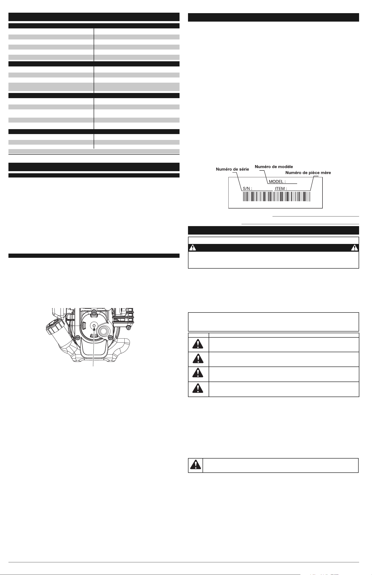
3. Retirez le bouchon / la jauge d'huile du carter-moteur. Versez tout le contenu de la
bouteille d'huile dans le carter-moteur (Fig. 6).
4. Versez tout le contenu de la bouteille d'huile dans le carter-moteur (Fig. 5).
REMARQUE : n’ajoutez jamais d'huile au carburant ni au réservoir de carburant.
5. Essuyez toute trace d'huile déversée et replacez le bouchon de remplissage / la jauge.
Nous ne saurions trop insister sur l'importance de la vérification du niveau d'huile du carter-moteur et de son
maintien. Vérifiez l'huile avant chaque utilisation et changez-la au besoin tel qu'indiqué dans la section Changment d'Huile.
66
FAMILIARISEZ-VOUS AVEC L’APPAREIL
APPLICATIONS
• Travailler le gazon et les sols meubles
ou semi meubles.
• Travailler les plates-bandes, autour
des arbres, etc.
• Découpage de bord
Manette
des gaz
Bouton du
guidon
Guidon
Bougie
Poignée de la
corde de
démarrage
Protecteur
des dents
Silencieux
Commande Marche/Arrêt
Dents
Support de la roue
Bouchon du
carburant
Levier d'étrangleur
INFORMATIONS SUR L'HUILE ET LE CARBURANT
INSTRUCTIONS DE MONTAGE
• SYMBOLES DE SÉCURITÉ ET INTERNATIONAUX •
Ce manuel de l'utilisateur décrit les symboles et pictogrammes de sécurité et internationaux pouvant
apparaître sur ce produit. Consultez le manuel de l'utilisateur pour les informations concernant la
sécurité, le montage, le fonctionnement, l'entretien et les réparations.
• Appuyez sur la manette des gaz et vérifiez que le régime du moteur revienne automatiquement au ralenti.
Effectuez tous les réglages et réparations avant d’utiliser l’appareil.
ALERTES DE SECURITE POUR LES APPAREILS A ESSENCE
• Stockez uniquement le carburant dans des conteneurs prévus spécifiquement à cet effet et approuvés
pour le stockage de telles substances.
• Evitez tout ce qui pourrait enflammer le carburant renversé. Ne démarrez pas le moteur avant que les
vapeurs de carburant ne se soient dissipées.
• Coupez toujours le moteur et laissez-le refroidir avant de remplir le réservoir d’essence. Ne retirez jamais
le bouchon du réservoir d’essence et ne remplissez jamais ce dernier lorsque le moteur est chaud. Ne
démarrez jamais l’appareil sans avoir bien revissé le bouchon du réservoir d’essence. Dévissez lentement
le bouchon du réservoir d’essence afin de réduire la pression.
• Ajoutez le carburant en extérieur, dans une zone propre, bien aérée, et dépourvue de toute source
d’étincelles ou de flammes. Dévissez lentement le bouchon du réservoir d’essence uniquement après
avoir arrêté le moteur. Ne fumez pas en remplissant le réservoir ou en mélangeant le carburant. L’essence
s’étant échappée de l’appareil doit être essuyée immédiatement. Essuyez l’appareil systématiquement
avant utilisation.
• Eloignez l’appareil d’au moins 30 pieds (9,1 m) du site et de la source du carburant avant de démarrer le
moteur. Ne fumez pas ou assurez-vous qu’il n’y a pas de source d’étincelles et de flammes, à proximité,
lorsque vous ajoutez du carburant ou faites tourner l’appareil.
LORS DU FONCTIONNEMENT DE L'APPAREIL
• L'appareil ne doit pas être démarré ou opéré à l'intérieur d'un espace ou d’un bâtiment clos. L’inhalation
des fumées d’échappement peut être fatale. Cet appareil doit fonctionner uniquement en extérieur, dans
une zone bien aérée.
• Portez des lunettes de sécurité conformes aux normes ANSI Z87.1–1989, lesquelles doivent être
indiquées sur les lunettes mêmes. Portez des bouchons d’oreille et des casques antibruit lors de
l’utilisation de cet appareil. Portez un masque si l'appareil émet de la poussière.
• Portez un pantalon long et épais, des bottes, des gants et une chemise à manches longues. Ne portez
pas de vêtements amples, de bijoux, de pantalons courts, de sandales et ne soyez pas pieds nus. Veillez
à ce que vos cheveux restent au-dessus du niveau des épaules.
• Cet appareil dispose d’un embrayage. Les dents reste immobile lorsque le moteur tourne au ralenti. Dans
le cas contraire, faites ajuster cet appareil par un technicien agréé.
• Assurez-vous que les dens n’est pas en contact avec tout autre élément avant de démarrer l’appareil.
• Utilisez cet appareil uniquement en plein jour ou si vous disposez d’un éclairage artificiel suffisant.
• Evitez les démarrages accidentels. Soyez en position de démarrage lorsque vous tirez sur le cordon du
démarreur. L’utilisateur et l’appareil doivent être sur un sol ferme lors du démarrage. Référez-vous aux
consignes relatives au démarrage/à l’arrêt de l’appareil.
• Utilisez le bon outil. N’utilisez pas un outil pour des fonctions pour lesquelles il n’a pas été prévu.
• Soyez très prudent lorsque vous faites marche arrière ou que vous tirez l’appareil vers vous.
• N’étendez pas trop le bras. Restez toujours à distance et en équilibre.
• Tenez toujours l’appareil à deux mains lorsqu'il est en marche. Assurez une prise ferme sur les deux
poignées ou grips.
• Gardez vos mains, votre visage et vos pieds à distance des parties en mouvement. Ne touchez pas et ne
tentez pas d'arrêter les dents lorsqu'il est en rotation.
• Ne touchez pas au moteur, à la transmission ou au pot d'échappement. Ces parties deviennent
extrêmement chaudes lors du fonctionnement, même après l'arrêt de l'appareil.
• L'appareil ne doit pas fonctionner à un régime supérieur à celui adapté pour cultiver. Ne faites pas
tourner le moteur à haut régime lorsque vous ne labourez pas.
• Coupez toujours le moteur lorsque vous interrompez le labourage ou lorsque vous vous rendez d’un
champ à un autre.
• Si vous butez ou bloquez sur un objet, arrêtez le moteur immédiatement et vérifiez que l'appareil n'a pas
été endommagé. Ne redémarrez pas l'appareil avant de l'avoir réparé. Ne faites pas fonctionner l’appareil
si certaines pièces ont du jeu ou sont endommagées.
• Arrêtez l’appareil, coupez le moteur, et déconnectez la bougie avant de l’entretenir ou de le réparer.
• Pour cet appareil, utilisez uniquement les pièces et accessoires de rechange du fabricant. Ils sont
disponibles auprès d’un fournisseur officiel. L’utilisation de pièces ou accessoires non agréés pourrait
entraîner de graves blessures pour l'utilisateur, ou endommager l'appareil, et annuler votre garantie.
• Dégagez l’herbe et les autres substances nichées dans l’appareil. Elles peuvent se coincer entre les
dents et l’écran.
• Afin de réduire les risques d’incendie, remplacez les réducteurs anti-flamme et les pots d’échappement
défaillants. Nettoyez l’herbe, les feuilles, les couches de graisse excessives et les dépôts de carbone du
moteur et du pot d’échappement.
APRES UTILISATION
• Nettoyez les dents à l’aide d’un produit d’entretien d’intérieur afin de retirer les dépôts. Graissez les dents
à l'huile pour l’empêcher de rouiller.
AUTRES MISES EN GARDE DE SECURITE
• N’entreposez jamais un appareil à essence à l’intérieur d’un bâtiment où les vapeurs peuvent entrer en
contact avec toute source de flammes ou d’étincelles.
• Laissez refroidir le moteur avant de le ranger ou de le déplacer. Lorsque vous déplacez l’appareil,
assurez-vous qu’il ne pose aucun danger.
• Entreposez l’appareil dans une zone sèche, verrouillée ou hors de la portée des enfants.
• Ne mouillez ou ne pulvérisez jamais d’eau ou tout autre liquide, sur l’appareil. Veillez à ce que les
poignées restent sèches, propres et dépourvues de tout dépôt. Nettoyez l’appareil après chaque
utilisation, voir les consignes portant sur le nettoyage et le stockage.
• Conservez ces consignes. Consultez-les souvent et utilisez-les pour mettre en garde les autres
utilisateurs. Si vous prêtez cet appareil à quelqu'un, donnez-lui ces consignes.
CONSERVEZ CES CONSIGNES
CONSIGNES DE SÉCURITÉ
POSITIONNEMENT DES POIGNÉES
1. Desserrez les deux boutons à l’intérieur des
poignées (Fig. 1).
2. Tenez l'appareil droit et placez les poignées en
position de fonctionnement (Fig. 2).
REMARQUE : Prenez soin de ne pas pincer le
câble de la manette ni les fils du
contact d'allumage lorsque vous
positionnez les poignées.
3. Vissez les boutons pour maintenir les poignées
en place.
REMARQUE : Évitez de trop serrer les boutons.
4. Rebranchez le couvre-borne de bougie.
RÉGLAGE DE LA PROFONDEUR DES DENTS
Procédez de la façon suivante pour ajuster le support de la roue :
1. Coupez le moteur et débrancher la bougie pour éviter tout démarrage accidentel.
2. Enlevez l'agrafe de la goupille fendue et glissez l'épingle de chape hors de la
parenthèse de queue (Fig. 3).
3. Faites glisser le support de la roue vers le haut ou le bas dans la partie arrière en
alignant les trous à la hauteur désirée.
4. Placez la goupille fendue par le trou et la fixez avec l'agrafe.
AVERTISSEMENT :
n'utilisez jamais la désherbeuse sans protecteur d'accessoire de coupe pour
éviter des blessures graves.
AVERTISSEMENT :
L'essence est extrêmement inflammable et ses vapeurs peuvent
exploser si on y met le feu. Veuillez prendre les précautions suivantes.
Bouton du
guidon
Rondelle
Boulon
Fig. 1
Fig. 2
Buse
d'entonnoir
Fig. 4
Fig. 5
Bouchon de
remplissage
Joint
torique
Orifice de
remplissage d’huile
Fig. 6
AVERTISSEMENT :
LE REMPLISSAGE EXCESSIF DU CARTER-MOTEUR PEUT ANTRAÎNER DES
BLESSURES GRAVES. Nous ne saurions trop insister sur l'importance de la vérification du niveau d'huile
du carter-moteur et de son maintien. Vérifiez l'huile avant chaque utilisation et changez-la au besoin tel
qu'indiqué dans la section Changment d'Huile.
SYMBOLE SIGNIFICATION
• SURFACE CHAUDE
AVERTISSEMENT : Ne touchez pas un silencieux ou un cylindre chaud. Vous
pourriez vous brûler. Ces pièces deviennent très chaudes à l'utilisation. Elles restes
chaudes brièvement après l'arrêt.
• NIVEAU D'HUILE
Voir le manuel de l'utilisateur pour le type d'huile approprié.
• ETRANGLEUR
1 • Position d’étranglement MAXIMUM
2 • Position d’étranglement PARTIEL
3 • Position de MARCHE
• CULTIVATEURS – LES DENTS ROTATIVES PEUVENT BLESSER GRIÈVEMEN
AVERTISSEMENT : Arrêtez le moteur et laissez les dents s’arrêter avant d’en
installer ou en retirer, ou d’entreprendre un nettoyage ou entretien. Gardez les mains et
les pieds éloignés des dents en rotation.
SYMBOLE SIGNIFICATION
• SYMBOLE ALERTE DE SÉCURITÉ
Indique un danger, un avertissement ou une mise en garde. Ce symbole peut être
combiné à d'autres symboles ou pictogrammes.
• LISEZ LE MANUEL DE L'UTILISATEUR
AVERTISSEMENT : Lisez le manuel de l'utilisateur et suivez tous les avertissements
et consignes de sécurité. Vous pourriez à défaut entraîner des blessures graves pour vous
ou d'autres personnes.
• PORTEZ DES PROTECTIONS (YEUX ET OREILLES)
AVERTISSEMENT : les objets projetés et les bruits forts peuvent endommager la
vue et l’ouïe. Portez une visière de norme ANSI Z87.1-1989 et des protège-oreilles
pendant l'utilisation.
• CARBURANT SANS PLOMB
Utilisez toujours du carburant sans plomb frais et propre.
• COMMANDE MARCHE/ARRÊT
ALLUMAGE/DÉMARRAGE/MARCHE
• COMMANDE MARCHE/ARRÊT
ARRÊT ou STOP
• N’UTILISEZ PAS DE L’ESSENCE E85 DANS CET APPAREIL
AVERTISSEMENT : Il a été prouvé que l’utilisation de carburant contenant plus
de 15% d’éthanol est susceptible d’endommager ce moteur et annulera la garantie.
• LES OBJETS PROJETÉS ET LA TÊTE ROTATIVE PEUVENT CAUSER DES
BLESSURES GRAVES
AVERTISSEMENT : ne faites pas fonctionner sans protecteur de sécurité en
plastique. Tenez-vous à l'écart de le tête de coupe rotatif.
• ÉLOIGNEZ LES SPECTATEURS
AVERTISSEMENT : éloignez tout spectateur, les enfants et les animaux
domestiques en particulier, d'au moins 15 m (50 pi) de la zone de coupe.
CONSIGNES DE SÉCURITÉ
Poire
d'amorçage
Couvercle
du filtre à air
Support de la
roue
Support de la
partie arrière
Fig. 3
Agrafe
Goupille
fendue
Page 7

TYPE CARBURANT RECOMMANDÉ
En général, si l'appareil ne fonctionne pas correctement, c'est que le carburant est vieux ou mal mélangé. Prenez soin
d'utiliser du carburant sans plomb frais et propre.
REMARQUE : ceci est un moteur à quatre temps. Pour éviter d’endommager l’appareil, ne mélangez pas l’huile avec
l’essence.
Définition des carburants mélangés
Les carburants d'aujourd'hui sont souvent un mélange d'essence et d'oxygénés comme l'éthanol, le méthanol ou
l'éther MTBE. Un carburant mélangé à l'alcool absorbe l'eau. Il suffit de 1% d'eau pour séparer le carburant et l'huile,
ce qui forme de l'acide pendant l'entreposage. Si vous devez utiliser ce type de carburant, servez-vous de carburant
frais (moins de 60 jours).
Usage de carburants mélangés
Si vous choisissez d'utiliser ou ne pouvez éviter d'utiliser un carburant mélangé, suivez les conseils suivants :
• Utilisez toujours un mélange de carburant frais selon le manuel de l'utilisateur.
• Utilisez l'additif STA-BILMD ou un produit équivalent.
• Agitez toujours le mélange de carburant avant d'alimenter l'appareil.
• Videz le réservoir et faites marcher le moteur jusqu'à ce qu'il soit à sec avant d'entreposer l'appareil.
UTILISATION D’ADDITIFS DE CARBURANT
L'utilisation d'additifs de carburant tel que le stabilisant d’essence STA-BILMD ou un produit équivalent permet d'empêcher
la corrosion et de minimiser la formation de résidus de gomme. L'usage d'additifs peut empêcher le carburant de former
des dépôts nocifs dans le carburateur pendant six (6) mois maximum. Ajoutez 23 ml (0,8 oz) d'additif par 4 litres (1 gallon)
de carburant selon les instructions du récipient. N'ajoutez JAMAIS d'additifs directement dans le réservoir de l'appareil.
AJOUR DE CARBURANT
1. Déposez le bouchon à carburant (fig. 7).
REMARQUE : Remplissez ou ajoutez du
carburant dans le réservoir uniquement
lorsque le cultivateur est en position
horizontale (Fig. 8).
2. Placez le bec du récipient d’essence dans
l’orifice du réservoir et remplissez celui-ci.
REMARQUE : Ne remplissez pas trop le réservoir.
3. Essuyez tout déversement d’essence.
4. Remettez le bouchon du réservoir.
5. Éloignez l'appareil d'au moins 9,1 m (30 pi) de la source et du site de ravitaillement en carburant avant de démarrer
le moteur.
REMARQUE : Éliminez le vieux carburant conformément aux règlements fédéral, provincial et municipal en vigueur.
CONSEILS D’UTILISATION
1. Déplacez le cultivateur vers le lieu de travail avant de démarrer le moteur. Vous pouvez le transporter sur ses roues
ou en le tenant par le tube central de la poignée.
2. Démarrez l’appareil conformément aux instructions de démarrage.
3. Pendant que le moteur tourne et que les dents ne touchent pas le sol, appuyez
sur la manette des gaz pour augmenter le régime du moteur.
4. Tout en tenant la poignée supérieure avec les deux mains, le cultivateur jusqu’à
ce que les dents touchent le sol (Fig. 12).
5. Dès que vous commencez à cultiver, inclinez légèrement l’appareil vers le haut à l’aide des poignées pour faire
pénétrer les dents dans le sol.
6. Une fois le sol entamé, continuez le travail d’un rythme modéré jusqu’à ce que vous vous sentiez à l’aise avec les
commandes et la manipulation du cultivateur.
7. Si les dents mordent trop profondément ou pas assez, réglez le support de roue selon la section Réglage de la
profondeur des dents.
TRANSPORT DE L’APPAREIL
1. Arrêtez le moteur.
2. Inclinez l’appareil vers l’arrière jusqu’à ce que les dents décollent du sol.
3. Poussez ou tirez l’appareil pour aller au lieu de travail suivant.
AVERTISSEMENT :
Pour éviter des blessures graves, ne soulevez
et ne transportez jamais l'appareil lorsque le moteur est en marche.
77
INSTRUCTIONS D’UTILISATION
AVERTISSEMENT :
Portez des vêtements appropriés pour diminuer les risques de blessures
durant l'utilisation de l'appareil. Ne portez pas de vêtements amples ni de bijoux. Portez des lunettes de
sécurité et des protège-oreilles. Portez des pantalons épais et longs, des bottes et des gants. Ne
marchez pas pieds nus et évitez les pantalons courts et les sandales.
Fig. 12
INSTRUCTIONS DE DÉMARRAGE ET ARRÊT
AVERTISSEMENT :
Les dents TOURNERONT quand
DÉMARRANT. Tenez-vous toujours en position de départ avec le
pied sur la roue en commençant l'unité.
AVERTISSEMENT :
évitez tout démarrage accidentel. Tenez-vous
en position de démarrage lorsque vous tirez sur la corde de démarrage
(Fig. 11). L'opérateur et l'appareil doivent tous deux être en position stable
pour éviter des blessures graves.
INSTRUCTIONS DE DÉMARRAGE
1. Remplissez le réservoir d’essence sans plomb propre et frais. Voir Ajout de
Carburant.
REMARQUE : Il n’est pas nécessaire de faire démarrer la machine. La commande
Arrêt/ Marche est en position Marche (I) en permanence (Fig. 9).
2. Lentement, appuyez 10 fois de suite sur la poire d’amorce. Une certaine quantité
de carburant devrait être visible dans la poire d'amorce (Fig. 10). Si l’essence
n’est pas visible dans la poire d’amorce, poussez et relâchez la poire jusqu’à ce
que l’essence soit visible.
3. Mettez le levier d'étrangleur en Position 1 (Fig. 10).
REMARQUE : Veillez à faire toujours incliner l'unité en arrière légèrement pour
apporter les dents outre de la terre en commençant.
4. Tenez le guidon et serrez la commande de commande de puissance avec une main
et saisissez la corde de démarreur avec l'autre main. Utilisant un pied pour maintenir
le cultivateur (Fig. 11). Tirez la corde de démarreur 5 fois.
5. Mettez le levier d'étrangleur en Position 2 (Fig. 10).
6. Appuyez sur la commande des gaz, tirez vivement le lanceur jusqu’à 3 to 5 fois
pour démarrer le moteur.
7. Maintenez la manette des gaz enfoncée et laissez le moteur chauffer pendant 30
à 60 secondes.
8. Tout en gardant enfoncée la manette des gaz, placez le levier d'étranglement dans la Position 3 (Fig. 10) et laissez
le moteur se réchauffer encore pendant 60 secondes. Pendant ce temps l’appareil peut être utilisé.
REMARQUE : La machine est bien chauffée lorsque le moteur accélère sans hésitation.
SI... Le moteur hésite, remettez le levier d'étranglement en Position 2 (Fig. 10) et continuez à le chauffer.
SI... Le moteur ne démarre pas, retournez à l’étape 4.
SI... Le moteur ne démarre toujours pas après quelques tentatives, placez le levier d'étranglement en Position 3,
appuyez sur le verrouillage de la manette des gaz et appuyez sur cette dernière.
SI CHAUD… Le moteur est déjà chaud, démarrez la machine avec le levier d'étranglement en Position 2. Après que la
machine ait démarré, mettez le levier d'étranglement en Position 3.
AVERTISSEMENT :
Il a été prouvé que l’utilisation de carburant contenant plus de 15% d’éthanol
est susceptible d’endommager ce moteur et annulera la garantie.
INFORMATIONS SUR L'HUILE ET LE CARBURANT
AVERTISSEMENT :
L'essence est extrêmement inflammable et les vapeurs qui s'en dégagent peuvent
exploser si on y met le feu. Arrêtez toujours le moteur et laissez-le refroidir avant de remplir le réservoir. Ne
fumez pas en remplissant le réservoir. Éloignez toute source d'étincelles ou de flammes vives de la zone.
AVERTISSEMENT :
Enlevez le bouchon du réservoir lentement pour ne pas être blessé par les jets
d'essence. Ne faites pas marcher l'appareil sans que le bouchon soit bien mis.
AVERTISSEMENT :
Ajoutez du carburant dans un lieu propre et bien aéré en plein air. Essuyez
immédiatement tout déversement de carburant. Évitez de mettre le feu au carburant déversé. Ne
démarrez pas le moteur avant dissipation des vapeurs de carburant.
COMMENT DÉMARRER L’APPAREIL À L’AIDE DES ACCESSOIRES DE DÉMARRAGE ÉLECTRIQUE OU
POWER START BIT™.
Remarque - Cet appareil peut utiliser les accessoires de démarrage électrique ou Power Start Bit™ disponibles
en option.
Veuillez consulter le manuel de l’utilisateur du démarreur électrique Electric Starter ou de l'embout de démarreur
électrique Power Start Bit™ pour savoir comment utiliser correctement ces fonctionnalités. (Articles vendus
séparément. Reportez-vous à la page 9 de ce manuel pour plus d’informations sur l'achat de ces accessoires.)
INSTRUCTIONS DE DÉMARRAGE
1. Remplissez le réservoir d’essence sans plomb propre et frais. Voir Ajout de Carburant.
REMARQUE : Il est inutile de mettre l’appareil en marche. La commande Marche/Arrêt est en position Marche ( I ) en
permanence (Fig. 9).
2. Lentement, pressez puis relâchez dix fois de suite la poire d’amorce. Une certaine quantité de carburant devrait
être visible dans la poire d'amorce (Fig. 10). Si l’essence n’est pas visible dans la poire d’amorce, pressez et
relâchez la poire jusqu’à ce que l’essence soit visible.
3. Mettez le levier d’étranglement en Position 1 (Fig. 10).
REMARQUE : Veillez à faire toujours incliner l'unité en arrière légèrement pour apporter les dents outre de la terre en
commençant.
4. Tenez le guidon et serrez la commande de commande de puissance avec une main et placez le démarreur
électrique ou Power Start Bit™ dans le dos de l'unité. Référez-vous à la section d'opération du démarreur
électrique ou Power Start Bit™ le manuel de l'opérateur.
5. Pressez le levier de la manette des gaz. Maintenez enfoncé pendant deux secondes le bouton de démarrage
électrique ou de mise en MARCHE de la perceuse (I).
6. Mettez le levier d’étranglement en Position 2 (Fig. 10).
7. Pressez le levier de la manette des gaz, maintenez enfoncé pendant deux secondes le bouton de démarrage
électrique ou de mise en MARCHE de la perceuse (I) jusqu’à ce que le moteur démarre.
8. Continuez de presser la manette des gaz, retirez le démarreur électrique ou la perceuse de l’appareil et laissez le
moteur se réchauffer pendant 30 à 60 secondes.
9. Continuez de presser la manette des gaz, placez le levier d’étranglement en Position 3 (Fig. 10) et laissez tourner le
moteur encore 60 secondes. L’appareil peut être utilisé pendant ce temps.
REMARQUE : L’appareil est suffisamment chaud lorsque le moteur accélère sans accrocs.
SI…
le moteur fait des accros, remettez le levier d’étranglement en Position 2 (Fig. 10) et continuez de chauffer le moteur.
SI… le moteur ne démarre pas, retournez à l’étape 3.
SI… le moteur ne démarre pas après plusieurs tentatives, placez le levier d’étranglement en Position 3 et
pressez la manette des gaz. Enfoncez à plusieurs reprises pendant deux secondes le bouton de démarrage
électrique ou de mise en MARCHE de la perceuse (I) jusqu’à ce que le moteur démarre.
S'IL EST CHAUD... Si le moteur est déjà chaud, démarrez le moteur avec le levier d’étranglement bleu en Position 2.
Après le démarrage du moteur, placez le levier d’étranglement bleu en Position 3.
SI VOUS UTILISEZ LE DEMARREUR ELECTRIQUE OU POWER START BIT™ DISPONIBLES EN OPTION
PROGRAMME D'ENTRETIEN
L'entretien doit respecter la fréquence indiquée dans le tableau ci-dessous. Il doit également faire partie de toute mise
au point saisonnière.
REMARQUE : certaines procédures d'entretien nécessitent des compétences ou des outils particuliers. Si vous n'êtes
pas sûr de pouvoir les entreprendre, emmenez votre appareil dans un atelier, chez un technicien ou un
concessionnaire agréé spécialisé dans les réparations de moteurs d’outils mécaniques de plein air.
REMARQUE : l'entretien, le remplacement ou la réparation des dispositifs et systèmes antipollution peuvent être
effectués par tout atelier, technicien ou concessionnaire agréé spécialisé dans les réparations de moteurs
d’outils mécaniques de plein air.
AVERTISSEMENT :
Pour éviter tout accident, n’effectuez jamais l’entretien ou des réparations
quand l’appareil fonctionne. Effectuez-les toujours lorsqu’il est froid. Débranchez le câble de la bougie
pour prévenir la mise en route.
INSTRUCTIONS D’ENTRETIEN ET RÉPARATIONS
RETIRER ET REMPLACER LES COUTEAUX
Toutes les dents devraient être remplacées en même temps qu'elles porteront même par l'utilisation normale. Travail
d'un côté à la fois.
1. Assurez-vous que l'unité est éteinte.
REMARQUE : Il peut être nécessaire d'étendre le cultivateur en arrière en position horizontale sur une surface de
niveau plate avec la poignée
supérieure touchant la terre. Il peut
également être nécessaire de laver
n'importe quelle saleté outre des dents
et de l'axe pour la facilité du
déplacement.
2. Enlevez l'agrafe de la goupille fendue qui est
entre les 2 dents externes (Fig. 14)
3. Enlevez la goupille fendue et glissez les dents
au loin de l'axe (Fig. 13).
4. Nettoyez et huilez l'axe.
5. Glissez sur les nouvelles dents avec les hub se faisant face (Fig. 13).
REMARQUE : Assurez-vous que la dent simple va sur l'axe de dent d'abord avec les doubles dents sur l'extérieur et
des trous sur les dents externes sont alignés avec le trou externe sur l'axe (Fig. 13).
6. Fixez les nouvelles dents à l'axe en glissant la goupille fendue dans les trous entre les 2 dents externes (Fig. 14)
7. Insérez l'agrafe dans la goupille fendue pour fixer les dents.
8. Répétez l'étape 2 à 7 pour le côté opposé.
VÉRIFICATION DU NIVEAU D'HUILE
Nous ne saurions trop insister sur l'importance de la
vérification du niveau d'huile du carter moteur et de
son maintien. Vérifiez l'huile avant chaque utilisation:
1. Arrêtez le moteur et laissez l’huile s’écouler
dans le carter moteur.
2. Placez la machine sur une surface plane avec
le bouclier de la tête de coupe pendant d’un
banc de travail ou d’une table pour obtenir une
lecture correcte du niveau d’huile (Fig. 15).
3. Empêchez l'accumulation de saleté, de résidus
de coupe, etc. dans le moteur. Nettoyez la zone autour du bouchon / jauge d'huile avant de le retirer.
4. Retirez le bouchon / jauge d'huile et essuyez toute trace d'huile. Replacez-le en l'enfonçant bien.
5. Le regard dans le pétrole remplit le trou, utiliser une lampe de poche si nécessaire. Le pétrole doit être juste
touchant l'intérieur plus fil (Fig. 16).
6. Si le niveau d’huile ne touche pas le filetage le plus à l’intérieur dans le trou de remplissage de l’huile, ajoutez une
petite quantité d’huile dans le trou de remplissage de l’huile et vérifiez à nouveau (Fig. 16). Répétez cette
procédure jusqu’à ce que le niveau d’huile atteigne le filetage le plus à l’intérieur du trou de remplissage d’huile.
REMARQUE : Ne remplissez pas trop l’appareil.
REMARQUE : Assurez-vous que le joint torique est mis sur le bouchon de remplissage / jauge d'huile au moment de la
vérification et du changement d'huile (Fig. 17).
CHANGEMENT D'HUILE
Si le moteur est neuf, changez l'huile après les 10
premières heures d’utilisation. Mieux vaut changer
l'huile lorsque le moteur est encore chaud. Cela lui
permet de s'écouler librement et d'emporter les
impuretés.
1. Débranchez le couvre-borne de bougie pour
empêcher le démarrage.
2. Retirez le bouchon de remplissage / jauge
d'huile (Fig. 17)
3. Versez l'huile de l’orifice de remplissage dans
un récipient en inclinant l'appareil à la verticale (Fig. 18). Allouez assez de temps pour une vidange complète.
Commande
Marche/Arrêt
Manette des gaz
Fig. 9
Poignée de
la corde de
démarrage
Fig. 11
Fig. 10
Poire d'amorçage
Levier
d'étrangleur
Bouchon du
carburant
Fig. 7
Fig. 8
Bec du récipient
d'essence
Réservoir
AVERTISSEMENT :
Pour éviter des blessures graves, faites très attention lorsque vous faites
marche arrière ou que vous tirez l’appareil vers vous.
AVERTISSEMENT :
Pour éviter des blessures graves, arrêtez toujours le moteur si le travail est
retardé ou si vous transportez l’appareil d’un lieu à l’autre.
Goupille
fendue
Fig. 14
MISE EN GARDE :
Pour éviter de trop user le moteur ou endommager l'appareil, maintenez toujours
l'huile du carter à un bon niveau. N’utilisez jamais l'appareil si le niveau est en dessous du bas de la jauge.
AVERTISSEMENT :
Pour empêcher le dommage corporel sérieux, portez toujours les gants lourds
en manipulant les dents.
Dents
externes
Moyeux
Dent
intérieure
Fig. 13
AVERTISSEMENT :
Pour éviter le dommage corporel sérieux, arrêtez toujours l'unité et
permettez-lui de se refroidir avant de le nettoyage ou l'entretenir
Fig. 16
Fig. 15
Huile en trait
plein
Agrafe
Axe de
dent
Alignez les trous
INSTRUCTIONS DE DÉMARRAGE ET ARRÊT
INSTRUCTIONS D'ARRÊT
1. Relâchez la manette des gaz. Laissez le moteur se refroidir au ralenti.
2. Appuyez sur la commande Marche/Arrêt et maintenez-la en position ARRÊT (O) jusqu'à ce que le moteur s’arrête
complètement (Fig. 9).
Fig. 18
FRECUENCIA MANTENIMIENTO REQUERIDO CONSULTE
Avant le démarrage du moteu
Remplissez le réservoir de carburant frais
Vérifiez l'huile
Pg 7
Pg 8
Toutes les 10 heures Nettoyez le filtre à air et lubrifiez-le de nouveau Pg 9
10 heures pour un moteur neuf
Toutes les 25 heures
Changez l'huile
Nettoyez le pare-étincelles
Pg 9
Pg 9
10 heures pour un moteur neuf
Toutes les 25 heures
Vérifiez et réglez le jeu entre soupape et culbuteur
Vérifiez l'état de la bougie et l'écartement des électrodes
Pg 9
Pg 9
Bouchon de
remplissage
Joint
torique
Orifice de
remplissage d’huile
Fig. 17
Page 8

CAUSE SOLUTION
Carburant vieux Drainez le réservoir/ajoutez du carburant frais
Des dents sont liées avec la saleté ou l'herbe Arrêtez le moteur et nettoyez les dents
Filtre à air sale Remplacez ou nettoyez-le
Pare-étincelles colmaté Nettoyez ou remplacez le pare-étincelles
CAUSE SOLUTION
Carburant vieux Drainez le réservoir/ajoutez du carburant frais
Bougie encrassée Remplacez ou nettoyez-la
Pare-étincelles colmaté Nettoyez ou remplacez le pare-étincelles
CAUSE SOLUTION
Réservoir de carburant vide Remplissez-le de carburant frais
La poire d'amorçage n'a pas été pressée assez fort Pressez-la complètement et lentement de 10 fois
Carburant vieux Drainez le réservoir/ajoutez du carburant frais
Bougie encrassée Remplacez ou nettoyez-la
Pare-étincelles colmaté Nettoyez ou remplacez le pare-étincelles
CAUSE SOLUTION
Filtre à air bouché Remplacez ou nettoyez-le
Carburant vieux Drainez le réservoir/ajoutez du carburant frais
Mauvais réglage du carburateur
Ajustez selon l'instruction ou faites-le régler par un
concessionnaire agréé
88
TABLEAU DE DÉPANNAGE
SI VOUS AVEZ BESOIN D'AIDE, CONTACTEZ VOTRE CONCESSIONNAIRE AGRÉÉ.
INSTRUCTIONS D’ENTRETIEN ET RÉPARATIONS
4. Essuyez les résidus d'huile et nettoyez toute trace d'huile déversée. Éliminez
l'huile selon les règlements fédéral, provincial et municipal en vigueur.
5.
Remplissez de nouveau le carter moteur de 90 ml (3,04 oz) d'huile SAE 30 SF, SG, SH.
REMARQUE : Mesurez la quantité nécessaire à l’aide de la bouteille et de la buse
utilisées lors de la mise en service. 90 ml (3,04 oz) correspond environ au
haut de l’étiquette de la bouteille (Fig. 19). Vérifiez le niveau d'huile avec la
jauge. S’il est trop bas, ajoutez un peu d'huile par l’orifice et revérifiez Ne
remplissez pas trop (Fig. 16).
6. Replacez le bouchon de remplissage / jauge d'huile.
7. Rebranchez le couvre-borne de bougie.
ENTRETIEN DU FILTRE À AIR
Nettoyage du filtre á aire
Nettoyez et relubrifiez le filtre à air à toutes les 10 heures de fonction-nement. C'est l'un des éléments les plus
importants pour l'entretien. Tout manquement à l’entretien du filtre à air peut entraîner une baisse de performances ou
causer des dégâts permanents à votre moteur.
1. Pour ouvrir le filtre à air, appuyez vers l’intérieur
sur la languette de fermeture et retirez ensuite
sur le couvercle du filtre à air (Fig. 20).
2. Retirez le filtre à air (Fig. 20).
3. Lavez le filtre dans un mélange d'eau et de
détergent (Fig. 21). Rincez le filtre
abondamment et laissez-le sécher.
4. Appliquez une quantité suffisante d'huile
moteur propre SAE 30 pour enduire légèrement
le filtre (Fig. 22).
5. Pressez le filtre pour répartir et drainer
l'excédent d'huile (Fig. 23).
6. Replacez le filtre à air dans la plaque de base
(Fig. 20).
REMARQUE :
Si vous faites fonctionner l'appareil sans
filtre à air, vous ANNULEREZ la garantie.
7.
Remettre le couvercle du filtre à air en place.
Positionnez les deux petites languettes sur le filtre
à air dans les encoches dans le panneau arrière et
poussez le couvercle du filtre à air vers le bas, en vous assurant d’aligner la languette de fermeture avec l’encoche de
verrouillage, jusqu’à ce que la languette se verrouille en place (Fig. 20).
RÉGLAGE DU CARBURATEUR
La vitesse de ralenti du moteur est réglable à l’aide d’une vis de réglage accessible par un trou situé sur le dessus du
couvercle du moteur (Fig. 24).
REMARQUE : Des réglages non soigneux peuvent endommager sérieusement l'appareil. Les réglages de carburateur
doivent être faits par un concessionnaire agréé.
Vérification du mélange de carburant
En général, si l'appareil ne fonctionne pas correctement, c'est que le carburant est vieux ou mal mélangé. Videz puis
remplissez le réservoir de carburant frais et bien mélangé avant d'effectuer des réglages. Voir la section Informations
sur l'huile et le carburant.
Nettoyage du filtre à air
L'état du filtre à air est très important pour le fonctionnement de l'appareil. Un filtre à air sale restreint le débit d'air et
affecte le mélange de carburant/air. On confond cela souvent avec un mauvais réglage du carburateur. Vérifiez l'état du
filtre à air avant de régler la vis de réglage de ralenti. Voir Entretien du filtre à air.
Réglage de la vis de réglage de ralenti
Si le moteur ne se met toujours pas au ralenti après vérification du mélange de
carburant et du nettoyage du filtre à air, réglez la vis de ralenti comme suit:
1. Démarrez le moteur et laissez-le tourner à haut régime pendant une minute pour
se réchauffer. Voir les Instructions de démarrage et d'arrêt.
2. Relâchez la manette des gaz et laissez le moteur tourner au ralenti. Si le moteur s’arrête, insérez un tournevis
cruciforme entre la couverture du filtre à air et celle du moteur (Fig. 24). Tournez la vis du ralenti dans le sens des
aiguilles d’une montre, 1/8 de tour à la fois (selon le besoin) jusqu’à ce que le moteur tourne au ralenti sans à-coups.
REMARQUE : Les dents ne devraient pas tourner quand le moteur tourne au ralenti.
3. Si les dents tourne quand le moteur tourne au ralenti, tournez la vis dans le sens contraire des aiguilles d'une
montre 1/8 de vitesse à vide d'un tour à la fois (comme nécessaire), pour réduire la vitesse à vide.
La vérification du mélange de carburant, le nettoyage du filtre à air et le réglage de la vis de ralenti devraient résoudre
la plupart des problèmes de moteur.Dans le cas contraire et si :
• Le moteur ne se met pas au ralenti,
• Le moteur hésite ou se cale lors d'une accélération,
• Le moteur perd de la puissance, faites régler le carburateur par un concessionnaire agréé.
JEU ENTRE SOUPAPE ET CULBUTEUR
Ceci nécessite de démonter le moteur. Si vous ne vous sentez pas à l'aise de le faire, confiez l'appareil à un centre de
service agréé.
REMARQUE : Inspectez le jeu entre soupape et culbuteur à l’aide d’une jauge d'épaisseur après les 10 premières
heures de fonctionnement, puis par intervalle de 25 heures par la suite.
• Attendez que le moteur soit froid avant de
vérifier ou de régler le jeu de la soupape.
• Faites-le à l'intérieur, dans un endroit propre et
sans poussière.
1. Retirez les six (6) vis à l’arrière de la couverture
du moteur avec un tournevis plat ou un
tournevis Torx T-25 (Fig. 25).
2. Déconnectez le câble de la bougie.
3. Nettoyez toute saleté de la bougie. Retirez la
bougie de la culasse en tournant la douille de
5/8 po à gauche.
4. Déposez le couvercle du moteur (Fig. 25).
5. Nettoyez toute saleté autour du cacheculbuteur. Retirez la vis retenant le cacheculbuteur à l’aide d’un tournevis à lame plate
large ou à mèche no. T-25 Torx (Fig. 26).
Enlevez le cache-culbuteur et le joint.
6. Tirez lentement sur la corde de démarrage
pour ramener le piston au sommet de sa
course dit « point mort haut ». Vérifiez que:
• Le piston est au sommet de sa course lorsqu’on regarde par le trou de la bougie (Fig. 26)
• Les deux culbuteurs se déplacent librement et les deux soupapes sont fermées
Si ce n'est pas le cas, répétez la procédure.
7. Glissez la jauge d'épaisseur entre le culbuteur et le ressort de rappel de la soupape. Mesurez le jeu entre la tige de
soupape et le culbuteur (Fig. 27). Faites-le pour les soupapes d’admission et d'échappement.
L'écart de jeu recommandé pour l'admission et l'échappement est de 0,076 – 0,152 mm (0,003 – 0,006 po). Servezvous d’une jauge d'épaisseur d’automobile standard de 0,127 mm (0,005 po). La jauge d'épaisseur devrait pouvoir
glisser entre le culbuteur et la tige de soupape en rencontrant une faible résistance mais sans coller (Fig. 27 et 28).
8. Si le jeu n'est pas conforme:
a. Tournez l'écrou de réglage à l'aide d'une clé de 8 mm (5/16 po) ou d'un tournevis à embout hexagonal (Fig. 28).
• Pour augmenter le jeu, tournez l'écrou de réglage vers la gauche.
• Pour réduire le jeu, tournez l'écrou de réglage vers la droite.
b. Revérifiez les deux jeux de soupape et réglez-les au besoin.
9. Replacez le cache-culbuteur en mettant un joint neuf. Serrez la vis avec un couple de serrage de 2,2–3,4 N•m (12
po•lb).
10. Vérifiez l'état de la bougie et replacez-la. Voir Remplacement de la bougie.
11. Replacez le câble de la bougie.
12. Replacez le couvercle du moteur. Vérifiez l'alignement du couvercle avant de serrer les vis. Vissez bien.
REMPLACEMENT DE LA BOUGIE
Utilisez une bougie ref. #753-05255, Champion RDZ19H ou similar. L'écartement
correct est de 0,635 mm (0,025 po). Retirez la bougie après 25 heures de
fonctionnement et vérifiez son état.
1. Arrêtez le moteur et laissez-le refroidir. Saisissez fermement le câble de la bougie
et retirez le capuchon de celle-ci.
2. Nettoyez toute saleté de la bougie. Retirez la bougie de la culasse en tournant la
douille de 5/8 po à gauche.
3.
Remplacez toute bougie fendillée, encrassée ou sale. Réglez l'écartement à 0,635 mm (0,025 po) à l'aide d'une jauge
d'épaisseur (Fig. 29).
AVERTISSEMENT :
Pour éviter le dommage corporel sérieux, arrêtez toujours l'unité et permettez-
lui de se refroidir avant de le nettoyage ou l'entretenir
AVERTISSEMENT :
Il se peut que l'accessoire de coupe tourne
pendant le réglage de la vitesse de ralenti. Portez des vêtements
protecteurs et respectez toutes les consignes de sécurité pour éviter
des blessures graves.
Fig. 23
Fig. 21
Fig. 22
AVERTISSEMENT :
Pour éviter le dommage corporel sérieux, arrêtez toujours l'unité et permettez-
lui de se refroidir avant de le nettoyage ou l'entretenir
INSTRUCTIONS D’ENTRETIEN ET RÉPARATIONS
4. Installez la bougie avec un écartement correct dans la culasse en tournant la douille de 5/8 po à droite jusqu'à la
bien visser.
Si vous utilisez une clé dynamométrique vissez avec les valeurs de couple suivantes 12,3-13,5 N•m (110-120 po•lb).
Évitez de trop serrer.
ENTRETIEN DU PARE-ÉTINCELLES
1. Retirez le couvercle du silencieux. Voir Jeu entre soupape et culbuteur.
2. Avec un tournevis plat ou une douille Torx T-20 et T-25, dévissez les vis attachant
la couverture du pare-étincelles au pot d’échappement. (Fig. 30).
3. Retirez la languette du couvercle du pare-étincelles hors du silencieux. Retirez le
couvercle du pare-étincelles.
4. Retirez l’écran du pare-étincelles du couvercle de celui-ci.
5. Nettoyez l’écran du pare-étincelles avec une brosse métallique ou remplacez-le.
6. Replacez l’écran, le couvercle et la vis du pare-étincelles.
NETTOYAGE
Nettoyez l'extérieur de l'appareil à l'aide d'une petite brosse. N'utilisez pas de détergents concentrés. Les nettoyants
ménagers contenant des huiles aromatiques tel que le pin et le citron, et les solvants tel que le kérosène peuvent
endommager le boîtier ou la poignée en plastique. Essuyez toute trace d'humidité à l'aide d'un tissu doux.
ENTREPOSAGE
• Ne rangez jamais l'appareil plein de carburant dans un lieu où les vapeurs peuvent atteindre une flamme vive ou des
étincelles.
• Laissez le moteur se refroidir avant de l'entreposer.
• Rangez l'appareil dans un lieu verrouillé pour éviter toute utilisation ou accident indésirable.
• Rangez l'appareil dans un lieu sec et bien aéré.
• Rangez l'appareil hors de la portée des enfants.
ENTREPOSAGE DE LONGUE DURÉE
Si vous comptez entreposer l'appareil pendant une longue période, appliquez la procédure suivante:
1. Videz tout le carburant du réservoir dans un récipient contenant le même mélange 2-temps. N'utilisez pas de
carburant stocké pendant plus de 60 jours. Éliminez le vieux mélange de carburant conformément aux règlements
fédéral, provincial et municipal en vigueur.
2. Démarrez le moteur, puis laissez-le tourner jusqu'à ce qu'il cale. Cela permet de s'assurer que le carburateur s'est
vidé de son carburant.
3. Laissez le moteur refroidir. Retirez la bougie et versez environ 30 ml (1 oz) d'huile moteur ou d'huile moteur 4-temps
de qualité dans le cylindre. Tirez lentement sur la corde de démarrage pour bien distribuer l'huile. Replacez la
bougie.
REMARQUE : Retirez la bougie et videz toute l'huile du cylindre avant de mettre en marche la désherbeuse après une
période d'entreposage.
4. Nettoyez soigneusement l'appareil et vérifiez qu'il ne comporte pas de pièces desserrées ou endommagées.
Réparez ou remplacez lespièces endommagées, puis serrez les vis, crous et boulons desserrés. L'appareil est alors
prêt pour l'entreposage.
TRANSPORT
• Laissez le moteur refroidir avant le transport.
• Attachez bien l'appareil lors du transport.
• Videz tout le carburant de l’appareil.
• Serrez le bouchon du réservoir avant le transport.
MISE EN GARDE :
Évitez de sabler, gratter ou nettoyer les
électrodes car de la saleté dans le moteur pourrait endommager le
cylindre.
Fig. 29
0.635 mm
(0.025 in.)
Fig. 20
Couvre du filtre à air
Filtre à air
Fente
Fig. 25
Trou de
bougie
Fig. 26
Cache-
culbuteur
Jauge
d'épaisseur
Fig. 27
Admission
Echappement
Fig. 28
0.076 -0.152mm
(0.003 - 0.006 in.)
Écrou de réglage
Tige de
soupape
Crochets
Languette
Culbuteur
Vis
Vis
Vis
1
23
Fig. 24
Vis de réglage du ralenti
Fig. 30
Silencieux
Écran pare-
étincelles
Couverture
T-25
Vis
T-20 Vis
Entaille
AVERTISSEMENT :
Pour éviter le dommage corporel sérieux, arrêtez toujours l'unité et permettez-
lui de se refroidir avant de le nettoyage ou l'entretenir
Fig. 19
Niveau de remplissage
LE MOTEUR REFUSE DE SE METTRE AU RALENTI
LE MOTEUR REFUSE DE SE METTRE AU RALENTI
LE MOTEUR REFUSE D’ACCÉLÉRER
LE MOTEUR MANQUE DE PUISSANCE
Page 9

LEA TODAS LAS INSTRUCCIONES ANTES DE OPERAR LA UNIDAD
• Lea las instrucciones cuidadosamente. Familiarícese con los controles y el uso adecuado de la unidad.
• No opere esta unidad cuando esté cansado, enfermo o bajo la influencia de alcohol, drogas o
medicamentos.
• Los niños y los adolescentes menores de 15 años de edad no deben usar la unidad. Los adolescentes
pueden hacerlo bajo la supervisión de un adulto.
• Todos los dispositivos de protección y los accesorios de seguridad deben estar instalados
adecuadamente antes de operar la unidad.
• Inspeccione la unidad antes de usarla. Reemplace las piezas dañadas. Verifique si hay fugas de
combustible. Asegúrese de que todos los fijadores estén en su lugar y asegurados. Reemplace las
piezas que estén agrietadas, astilladas o dañadas en cualquier forma. No opere la unidad con piezas
sueltas o dañadas.
• Inspeccione cuidadosamente el área antes de operar la unidad. Elimine todos los escombros y los
objetos duros o filosos tales como cristal, alambre, etc.
• Esté consciente del riesgo de lesión en la cabeza, las manos y los pies.
•
No permita niños, espectadores ni mascotas en el área. Los niños, los espectadores y las mascotas
deben estar fuera de un radio de 50 pies (15 m.) como mínimo; de todas formas los espectadores correrán
el riesgo de ser golpeados por objetos lanzados por la unidad. Se debe exhortar a los espectadores a que
usen protección para los ojos. Si se le acerca alguien apague la unidad de inmediato.
• Oprima el control del estrangulador y compruebe que regresa automáticamente a la posición de marcha
en vacío. Haga todos los ajustes o reparaciones antes de usar la unidad.
• IMPORTANTE INFORMACION DE SEGURIDAD •
LLAMADAS A APOYO AL CLIENTE
INDICE DE CONTENIDOS
Llamadas a apoyo al cliente . . . . . . . . . . . . . . . . . . . . . . . . . . . . . . . . . . . . . . . . . . . . . . . . . . . . . . . . .9
Normas para una operación segura . . . . . . . . . . . . . . . . . . . . . . . . . . . . . . . . . . . . . . . . . . . . . . . . . . .9
Conozca su unidad . . . . . . . . . . . . . . . . . . . . . . . . . . . . . . . . . . . . . . . . . . . . . . . . . . . . . . . . . . . . . . .10
Instrucciones de ensamble . . . . . . . . . . . . . . . . . . . . . . . . . . . . . . . . . . . . . . . . . . . . . . . . . . . . . . . .10
Información del aceite y del combustible . . . . . . . . . . . . . . . . . . . . . . . . . . . . . . . . . . . . . . . . . . . . . .10
Instrucciones de arranque y apagado . . . . . . . . . . . . . . . . . . . . . . . . . . . . . . . . . . . . . . . . . . . . . . . .11
Instrucciones de operación . . . . . . . . . . . . . . . . . . . . . . . . . . . . . . . . . . . . . . . . . . . . . . . . . . . . . . . .11
Instrucciones de mantenimiento y reparación . . . . . . . . . . . . . . . . . . . . . . . . . . . . . . . . . . . . . . . . . .11
Limpieza y almacenamiento . . . . . . . . . . . . . . . . . . . . . . . . . . . . . . . . . . . . . . . . . . . . . . . . . . . . . . . .12
Cuadro de solución de problemas . . . . . . . . . . . . . . . . . . . . . . . . . . . . . . . . . . . . . . . . . . . . . . . . . . .12
Especificaciones . . . . . . . . . . . . . . . . . . . . . . . . . . . . . . . . . . . . . . . . . . . . . . . . . . . . . . . . . . . . . . . . .13
Garantía . . . . . . . . . . . . . . . . . . . . . . . . . . . . . . . . . . . . . . . . . . . . . . . . . . . . . . . . . . . . . . . . . . . . . . .16
Toda la información, las ilustraciones y las especificaciones contenidas en este manual se basan en la
información más reciente disponible en el momento de impresión del manual. Nos reservamos el
derecho de hacer cambios en cualquier momento sin aviso previo.
Copyright © 2009 MTD SOUTHWEST INC. Todos los derechos reservados.
Llame 1-800-828-5500 en EE.UU. o al 1-800-668-1238 en Canada para obtener una lista de
distribuidores de servicio localizados cerca de usted. Para obtener más detalles sobre su unidad, visite
nuestro sitio en www.troybilt.com o www.troybilt.ca.
NO REGRESE SU UNIDAD AL VENDEDOR. PARA SOLICITAR SERVICIO POR LA GARANTIA,
DEBERA PRESENTAR PRUEBA DE SU COMPRA.
ESTE PRODUCTO ESTA CUBIERTO POR UNA O MAS PATENTES DE EE.UU., OTRAS PATENTES EN TRAMITE.
El servicio de esta unidad, ya sea durante o después del período cubierto por la garantía, debe ser
realizado solamente por un proveedor de servicios autorizado y aprobado.
Antes de que empiece a ensamblar su nuevo equipo, por favor ubique la placa que contiene el modelo
de la unidad y escriba esa información en el espacio en blanco aquí debajo. Aquí debajo se explica la
muestra de una placa del modelo.
Copie el número de serie aquí:
Copie el número del modelo/ pieza del fabricante aquí:
ADVERTENCIA:
Se deben seguir las siguientes reglas de seguridad cuando use la unidad.
Por favor lea estas instrucciones para su propia seguridad y las de los espectadores, antes de hacer
funcionar la unidad. Por favor mantenga estas instrucciones en un lugar seguro para uso futuro.
NORMAS PARA UNA OPERACION SEGURA
Los símbolos de seguridad se utilizan para llamar su atención sobre posibles peligros. Los símbolos
de seguridad y sus explicaciones merecen toda su atención y comprensión. Los símbolos de
seguridad no eliminan ningún peligro por sí mismos. Las instrucciones o advertencias que ofrecen
no substituyen las medidas adecuadas de prevención de accidentes.
NOTA: Le ofrece información o instrucciones que son esenciales para la operación o
mantenimiento del equipo.
PARACHISPAS
NOTA: Para los usuarios en tierras forestales de los EE.UU. y en los estados de California, Maine, Oregon
y Washington. Todos los terrenos forestales de los EE.UU. y el estado de California (Códigos de Recursos
Públicos 4442 y 4443), Oregon y Washington, requieren por decreto, que ciertos motores de combustión interna
que se hagan funcionar en zonas boscosas y/o zonas cubiertas por pastizales, estén equipados con un
parachispas, que sean mantenidos en buen estado de funcionamiento o que el motor sea construido, esté
equipado y sea mantenido para evitar incendios. Consulte los reglamentos pertinentes a esos requisitos con las
autoridades estatales o locales. El incumplimiento de esos requisitos puede responsabilizarle o someterle a la
imposición de una multa. Esta unidad fue equipada en la fábrica con un parachispas. Si requiere sustitución,
hay una Pantalla Parachispas disponible, Pieza #
753-06238
al contactar el departamento de servicio.
PROPOSICIÓN 65 DE CALIFORNIA
ADVERTENCIA
LAS EMISIONES DEL MOTOR DE ESTE PRODUCTO CONTIENEN SUBSTANCIAS QUIMICAS QUE EL
ESTADO DE CALIFORNIA CONOCE COMO CAUSANTES DECANCER, DEFECTOS DE NACIMIENTO U
OTROS DAÑOS REPRODUCTIVOS.
9
MOTEUR*
Largeur du chemin de culture (maximum). . . . . . . . . . . . . . . . . . . . . . . . . . . . . . . . . . . . . . . . . . . . . . . . 22,86 cm (9 po)
Profondeur de culture (maximum) . . . . . . . . . . . . . . . . . . . . . . . . . . . . . . . . . . . . . . . . . . . . . . . . . . . . . . 15,24 cm (6 po)
Poids (sans carburant) . . . . . . . . . . . . . . . . . . . . . . . . . . . . . . . . . . . . . . . . . . . . . . . . . . . . . . . . . . . . . . . . 11,5 kg (25 lb)
Type de moteur . . . . . . . . . . . . . . . . . . . . . . . . . . . . . . . . . . . . . . . . . . . . . . . . . . . . . . . . . . . . . Refroidi par air, 4-temps
Cylindrée. . . . . . . . . . . . . . . . . . . . . . . . . . . . . . . . . . . . . . . . . . . . . . . . . . . . . . . . . . . . . . . . . . . . . . . . . . 29 cc (1,8 po3)
Régime de fonctionnement . . . . . . . . . . . . . . . . . . . . . . . . . . . . . . . . . . . . . . . . . . . . . . . . . . . . . . . . . . . . . 6.800+ tr/min
Régime ralenti. . . . . . . . . . . . . . . . . . . . . . . . . . . . . . . . . . . . . . . . . . . . . . . . . . . . . . . . . . . . . . . . . . 2.800 - 3.600 tr/min
Type d'allumage. . . . . . . . . . . . . . . . . . . . . . . . . . . . . . . . . . . . . . . . . . . . . . . . . . . . . . . . . . . . . . . . . . . . . . . Électronique
Contact d'allumage. . . . . . . . . . . . . . . . . . . . . . . . . . . . . . . . . . . . . . . . . . . . . . . . . . . . . . . . . . . . . . Interrupteur berceau
Jeu de soupape. . . . . . . . . . . . . . . . . . . . . . . . . . . . . . . . . . . . . . . . . . . . . . . . . . . . . 0,076-0,152 mm (0,003-0,006 po)
Écartement de la bougie . . . . . . . . . . . . . . . . . . . . . . . . . . . . . . . . . . . . . . . . . . . . . . . . . . . . . . . . . 0,635 mm (0,025 po)
Lubrification . . . . . . . . . . . . . . . . . . . . . . . . . . . . . . . . . . . . . . . . . . . . . . . . . . . . . . . . . . . . . . . . . . . . . . . . . Huile SAE 30
Contenance en huile du carter moteur . . . . . . . . . . . . . . . . . . . . . . . . . . . . . . . . . . . . . . . . . . . . . . . . . . . 90 ml (3,04 oz)
Carburant . . . . . . . . . . . . . . . . . . . . . . . . . . . . . . . . . . . . . . . . . . . . . . . . . . . . . . . . . . . . . . . . . . . . . . . . . . . Sans plomb
Carburateur. . . . . . . . . . . . . . . . . . . . . . . . . . . . . . . . . . . . . . . . . . . . . . . . . . . . . . . . . . . . . . Membrane, toutes positions
Démarreur . . . . . . . . . . . . . . . . . . . . . . . . . . . . . . . . . . . . . . . . . . . . . . . . . . . . . . . . . . . . . . . Rembobinage automatique
Silencieux . . . . . . . . . . . . . . . . . . . . . . . . . . . . . . . . . . . . . . . . . . . . . . . . . . . . . . . . . . . . . . . . . . Chicane avec protection
Accélérateur . . . . . . . . . . . . . . . . . . . . . . . . . . . . . . . . . . . . . . . . . . . . . . . . . . . . . . . . . . . . . . . . . . . . . . À rappel manuel
Capacité du réservoir de carburant . . . . . . . . . . . . . . . . . . . . . . . . . . . . . . . . . . . . . . . . . . . . . . . . . . . . . . 414 ml (14 oz)
CULTIVATEUR*
SPECIFICATIONS
*Toutes les spécifications contenues dans ce manuel tiennent compte des dernières informations techniques disponibles au
moment de mettre sous presse. Nous nous réservons le droit d'y apporter des modifications à tout moment, sans préavis.
FONCTIONNALITÉS DÉMARREUR ÉLECTRIQUE ET POWER START BIT™
Cet appareil est conçu pour être démarré avec un démarreur électrique ou Power Start Bit™ qui sont vendus séparément.
Si vous choisissez de démarrer l'appareil à l’aide de l'une de ces fonctionnalités ou si vous avez des questions, contactez
votre distributeur local ou appelez le 1-800-828-5500 si vous résidez aux États-Unis, (1-800-668-1238 au Canada) pour
plus d’informations ou connaître les points de vente. Vous pouvez également visiter le site Internet www.troybilt.com ou
www.troybilt.ca.
Démarreur électrique
NOTA: ¡Esta unidad puede utilizar un arrancador eléctrico o un accesorio de arranque
opcional Power Start Bit™!
Para informarse sobre el uso adecuado de estos sistemas, consulte el manual del operador del
arrancador eléctrico o accesorio de opcional Power Start Bit™. (Se vende por separado) En la
página 5 de este manual encontrará la información necesaria para comprar estos accesorios).
Lea el manual del operador y siga todas las advertencias e instrucciones de seguridad. De no
hacerlo, el operador y/o los espectadores pueden sufrir graves lesiones.
SI TIENE PREGUNTAS, LLAME AL 1-800-828-5500 EN EE.UU. O AL 1-800-668-1238 EN CANADA
SIMBOLO SIGNIFICADO
ADVERTENCIA:
El no seguir una advertencia de seguridad puede conducir a que
usted u otras personas sufran lesiones. Siga siempre las precauciones de seguridad
para reducir el riesgo de incendio, descarga eléctrica y lesiones personales.
PRECAUCIÓN:
El no seguir una advertencia de seguridad puede conducir a daño
patrimonial o a que usted u otras personas sufran lesiones personales. Siga siempre las
precauciones de seguridad para reducir el riesgo de incendio, descarga eléctrica y
lesiones personales.
ALERTA DE SEGURIDAD:
Indica peligro, advertencia o precaución. Debe
prestar atención para evitar sufrir graves lesiones personales. Puede ser utilizado junto
con otros símbolos o figuras.
PELIGRO:
El no obedecer una advertencia de seguridad puede conducir a que usted
u otras personas sufran graves lesiones. Siga siempre las precauciones de seguridad
para reducir el riesgo de incendio, descarga eléctrica y lesiones personales.
Page 10

COLOCACIÓN DEL MANUBRIO
1. Afloje las dos perillas del lado interior del
manubrio (Fig. 1).
2. Con la unidad en posición vertical, gire el
manubrio hacia arriba hasta la posición de
operación (Fig. 2).
NOTA: Tenga cuidado de no pellizcar el cable
del regulador o los cables del
interruptor cuando coloque el
manubrio.
3. Ajuste las perillas para asegurar el manubrio en
su lugar.
NOTA: No ajuste las perillas demasiado.
4. Vuelva a conectar la bujía de encendido.
AJUSTE DE LA PROFUNDIDAD
Para ajustar la ménsula de soporte de la rueda proceda de la siguiente manera:
1. Detenga el motor y desconecte la bujía para evitar un arranque accidental.
2. Quite el clip de la chaveta y resbale el perno de horquilla del soporte de la cola
(Fig. 3).
3. Deslice la ménsula de soporte de la rueda hacia arriba o hacia abajo en la pieza
posterior, alineando los orificios a la altura deseada.
4. Coloque la chaveta a través del agujero y asegúrela con el clip.
1010
CONOZCA SU UNIDAD
APLICACIONES
• Cultivar tierra herbosa y tierra negra
ligera a mediana.
• Cultivar áreas de jardines, alrededor
de árboles, etc.
• Recortar los bordes.
Gatillo del
regulador
Perillas del
manubrio
Bujía de encendido
Manubrio
Protección de
las púas
Silenciador
Control de encendido y
apagado
Púas
Ménsula de Soporte de
la Rueda
Tapa del
combustible
Palanca del
obturador
TIPO DE ACEITE RECOMENDADO
El uso de un aceite del tipo y peso correctos en el cigüeñal es extremadamente importante. Verifique el aceite antes de
cada uso y cambie el aceite con frecuencia. Si no usa el aceite correcto, o utiliza aceite sucio, puede causar el
desgaste y falla prematuros del motor.
Use un aceite de buena calidad SAE 30 de API (American Petroleum Institute) clase de servicio SG, SF, SH.
CARGA E ACEITE EN EL CARTER DEL
CIGÜEÑAL: USO INICIAL
NOTA: Esta unidad se envía sin carga de
aceite. A fin de evitar el daño de la
unidad, cargue aceite en el cárter del
cigüeñal antes de intentar arrancar la
unidad.
Su unidad trae una botella de aceite SAE 30 SF,
SG, SH de 90 ml (3,04 onzas fluidas) (Fig. 4).
NOTA: Guarde la botella para medir la
cantidad correcta de aceite cuando deba cambiarlo en el futuro. Lea
Cambio de Aceite.
1. Desenrosque la tapa de la botella de aceite y retire el sello de papel que cubre la
apertura. Vuelva a colocar la tapa. Corte la punta de la boquilla del embudo (Fig. 4).
2. Coloque la unidad sobre una superficie plana.
3. Saque el tapón de aceite/ varilla de medición del cigüeñal (Fig. 6).
4. Vierta todo el contenido de la botella de aceite en el cigüeñal (Fig. 5).
NOTA: No agregue nunca aceite al gasolina o al tanque de gasolina.
5. Limpie todo el aceite que pueda haberse derramado y vuelva a instalar el tapón
del aceite / varilla de medición.
No podemos exagerar la importancia del control y mantenimiento del nivel correcto de aceite en el cigüeñal. Verifique
el aceite antes de cada uso y cámbielo cuando sea necesario según se indica en la sección de Cambio del aceite.
TIPO DE GASOLINA RECOMENDADO
La gasolina viejo es la causa principal del mal funcionamiento de la unidad. Asegúrese de usar gasolina nueva, limpio y
sin plomo.
NOTA: Este es un motor de cuatro ciclos. Para evitar dañar su unidad, no mezcle el aceite con la gasolina.
INFORMATIONS SUR L'HUILE ET LE CARBURANT
INSTRUCCIONES DE ENSAMBLE
ADVERTENCIA:
No opere nunca la recortadora sin el protector accesorio de corte colocado en su
lugar para evitar graves lesiones personales.
• SIMBOLOS DE SEGURIDAD E INTERNACIONALES •
Este manual del operador describe los símbolos y figuras de seguridad e internacionales que pueden
aparecer en este producto. Lea el manual del operador para obtener información completa acerca de
la seguridad, ensamble, operación y mantenimiento y reparación.
AVISOS DE SEGURIDAD PARA LAS UNIDADES QUE FUNCIONAN CON GASOLINA
• Almacene el combustible solamente en recipientes diseñados y aprobados específicamente para el
almacenamiento de dichos materiales.
• Evite crear una fuente de ignición para el combustible derramado. No arranque el motor hasta que se
disipen los vapores del combustible.
• Pare siempre el motor y deje que se enfríe antes de llenar el tanque de combustible. Nunca quite la tapa
del tanque de combustible, ni agregue combustible, cuando el motor esté caliente. Nunca opere la
unidad sin la tapa de combustible bien colocada en su lugar. Afloje la tapa del tanque de combustible
lentamente para aliviar cualquier presión que haya en el tanque.
• Agregue el combustible en un área exterior bien ventilada, donde no haya chispas ni llamas. Quite
lentamente la tapa de combustible sólo después de haber parado el motor. No fume mientras esté
llenando de combustible o mezclándolo. Limpie de la unidad inmediatamente cualquier combustible
derramado. Seque siempre la unidad antes de usarla.
• Mueva siempre la unida a 30 pies (9.1 m) como mínimo de la fuente y sitio de combustible antes de
arrancar el motor. No fume ni permita chispas ni llamas expuestas cerca del área mientras esté
agregando combustible u operando la unidad.
CUANDO ESTÉ OPERANDO
• Nunca arranque ni opere la unidad dentro de un cuarto o edificio cerrado. Respirar los vapores del
escape puede ser fatal. Opere esta unidad solamente en un área exterior bien ventilada.
• Use gafas protectoras que cumplan con la norma Z87.1–1989 de ANSI y tengan la marca que lo indica.
Use protección para la oreja/audición cuando opere esta unidad. Use máscara facial o para polvo si la
operación produce mucho polvo.
• Use pantalones largos fuertes, botas, guantes y camisa de mangas largas. No use ropa holgada, joyas,
pantalones cortos, sandalias, ni esté descalzo. Asegúrese el cabello por encima del nivel de los
hombros.
• Esta unidad tiene un embrague. Las púas permanece estacionario cuando la unidad está en marcha en
vacío. Si no sucede así, haga que un técnico de servicio autorizado ajuste la unidad.
• Antes de arrancar la unidad asegúrese de que las púas no esté en contacto con nada.
• Use la unidad solamente de día o con buena luz artificial.
• Evite arranques accidentales. Esté en la posición de arranque cada vez que hale la cuerda de arranque.
El operador y la unidad deben estar en una posición estable al arrancar. Consulte las Instrucciones de
Arranque/Parada.
•
Use la herramienta correcta. Use esta herramienta solamente para el propósito para el cual fue diseñada.
• Tenga mucho cuidado cuando invierta o mueva la unidad hacia usted.
• No se estire demasiado. Mantenga siempre la base de apoyo y equilibrio adecuados. Tenga mucho
cuidado cuando trabaje en pendientes marcadas o inclinadas.
• Sostenga siempre la unidad con ambas manos cuando la opere. Mantenga un agarre firme sobre
ambas manijas.
• Mantenga las manos, la cara y los pies alejados de todas las partes en movimiento. No toque ni trate de
parar los dientes cuando estén girando.
• No toque el motor o el silenciador. Estas piezas están muy calientes durante la operación, incluso
después de que se apaga la unidad.
• No opere el motor a más velocidad de la necesaria para cultivo. No haga funcionar el motor a alta
velocidad cuando no esté cultivo.
•
Pare siempre el motor cuando deje de cultivo o cuando esté caminando de un lugar de cultivo hacia otro.
• Si golpea o se enreda con un objeto extraño, pare el motor inmediatamente y verifique si ha habido algún
daño. No lo opere antes de reparar el daño. No opere la unidad con piezas sueltas o dañadas.
• Pare la unidad, apague el motor y desconecte la bujía para mantenimiento o reparación.
• Use solamente piezas y accesorios de reemplazo del fabricante del equipo original para esta unidad.
Éstos están disponibles en su proveedor de servicio autorizado. El uso de cualquier pieza o accesorio
no autorizado podría causar lesiones graves al usuario, o daños a la unidad, y anular su garantía.
• Mantenga la unidad limpia de vegetación y otros materiales. Pudieran quedar obstruidas entre las púas
y el protector.
• Para reducir el peligro de incendio reemplace un silenciador y amortiguador de chispas defectuoso.
Mantenga el motor y el silenciador libre de hierba, hojas, exceso de grasa o acumulación de carbón.
DESPUÉS DE USARLA
• Limpie las púas con un limpiador casero para eliminar la acumulación de resina. Aceite las púas con
aceite de máquina para evitar la corrosión.
OTROS AVISOS DE SEGURIDAD
• Nunca almacene una unidad con combustible dentro de un edificio en el cual los vapores puedan llegar
a una llama expuesta o una chispa.
• Deje que el motor se enfríe antes de almacenarlo o transportarlo. Asegúrese de fijar bien la unidad
mientras la transporta.
• Almacene la unidad en un área seca y cerrada, o en un lugar alto para evitar uso no autorizado o daños.
Manténgala alejada del alcance de los niños.
• Nunca rocíe ni chorree la unidad con agua ni ningún otro líquido. Mantenga las manijas secas, limpias y
libres de escombros. Límpiela después de usarla, vea las instrucciones de Limpieza y Almacenamiento.
• Conserve estas instrucciones. Consúltelas con frecuencia y úselas para instruir a otros usuarios. Si le
presta esta unidad a alguien, préstele también estas instrucciones.
GUARDE ESTAS INSTRUCCIONES
CONSIGNES DE SÉCURITÉ
ADVERTENCIA:
La gasolina es muy inflamable y sus gases pueden explotar si se
encienden. Tome las siguientes precauciones:
Perillas del
manubrio
Arandela
Perno
Fig. 1
Fig. 2
Boquilla del
embudo
Fig. 4
Fig. 5
Tapón de
relleno de
aceite
Anillo en “O”
Orificio de
llenado de aceite
Fig. 6
AVERTISSEMENT :
LE REMPLISSAGE EXCESSIF DU CARTER-MOTEUR PEUT ANTRAÎNER DES
BLESSURES GRAVES. Nous ne saurions trop insister sur l'importance de la vérification du niveau d'huile
du carter-moteur et de son maintien. Vérifiez l'huile avant chaque utilisation et changez-la au besoin tel
qu'indiqué dans la section Changment d'Huile.
ADVERTENCIA:
Se ha demostrado que el combustible que contiene más del 15% de etanol
probablemente ocasionará daños al motor y anulará la garantía.
SYMBOLE SIGNIFICADO
• SIMBOLO DE ALERTA DE SEGURIDAD
IIndica peligro, advertencia o precaución. Puede ser utilizado junto con otros símbolos o figuras.
• LEA EL MANUAL DEL OPERADOR
ADVERTENCIA:
Lea el manual del operador y siga todas las advertencias e instrucciones
de seguridad. De no hacerlo, el operador y/o los espectadores pueden sufrir graves lesiones.
• USE PROTECCION OCULAR Y AUDITIVA
ADVERTENCIA:
Los objetos arrojados por la unidad y el ruido fuerte pueden causar
graves lesiones oculares y pérdida auditiva. Utilice protección ocular que cumpla con las
normas ANSI Z87.1–1989 y protección auditiva cuando opere esta unidad. Use una careta
completa cuando la necesite.
• COMBUSTIBLE SIN PLOMO
Use siempre combustible limpio, nuevo y sin plomo.
• CONTROL DE ENCENDIDO Y APAGADO
ENCENDIDO /ARRANQUE /MARCHA
• CONTROL DE ENCENDIDO Y APAGADO
APAGADO o PARADO
• NO UTILICE COMBUSTIBLE E85 EN ESTA UNIDAD
ADVERTENCIA: Se ha demostrado que el combustible que contiene más del
15% de etanol probablemente ocasionará daños al motor y anulará la garantía.
• LOS OBJETOS DESPEDIDOS Y LA CUCHILLA ROTATIVA PUEDEN CAUSAR
GRAVES LESIONES
ADVERTENCIA: No opere esta unidad si la protección plástica de línea no está
colocada en su lugar. Manténgase alejado de la cabeza de corte giratorio.
• MANTENGA ALEJADOS A LOS ESPECTADORES
ADVERTENCIA: Mantenga a todos los espectadores, en especial a niños y
animales domésticos a por lo menos 50 pies (15 m.) del área de corte.
• DE SUPERFICIE CALIENTE
ADVERTENCIA: No toque un silenciador ni un cilindro caliente. Puede quemarse.
Estas partes se calientan mucho con el uso. Luego de apagarse permanecen
calientes durante un corto tiempo.
• INDICADOR DE ACEITE
Consulte el manual del operador para obtener información acerca del tipo correcto de aceite.
SYMBOLE SIGNIFICADO
• CONTROL DEL OBTURADOR
1 • Posición de OBTURACIÓN COMPLETA
2 • Posición de OBTURACIÓN PARCIAL
3 • Posición de MARCHA
• CULTIVADORES PARA JARDINES – LAS PUAS GIRATORIAS PUEDEN CAUSAR
GRAVES LESIONES
ADVERTENCIA: Apague el motor y espere que las púas se detengan antes de
instalar o sacar las púas, o antes de realizar la limpieza o todo tipo de mantenimiento.
Mantenga las manos y los pies lejos de las púas giratorias.
CONSIGNES DE SÉCURITÉ
Bombilla
del cebador
Cubierta del
filtro de aire
Soporte de la
Soporte Rueda
Ménsula de la
Pieza Posterior
Fig. 3
Clip
Chaveta
Page 11

1111
Definición de los gasolinas de mezcla
Las gasolinas actuales con frecuencia son una mezcla de gasolina y uno o más oxigenantes como el etano, el metanol
o el MTBE (éter). La gasolina con mezcla de alcohol absorbe agua. Un porcentaje de agua tan pequeño como el 1%
en la gasolina puede hacer que la gasolina y el aceite se separen. Se forman ácidos mientras está guardado. Cuando
use gasolina con mezcla de alcohol, use gasolina nueva (almacenado durante menos de 60 días).
Uso de los gasolinas de mezcla
Si decide usar un gasolina de mezcla o si su uso es inevitable, le recomendamos que tome las siguientes
precauciones:
• Use siempre una mezcla fresca de gasolina según lo indica su manual del operador
• Use Sta-Bil® o su equivalente
• Drene el tanque y haga funcionar el motor en seco antes de guardar la unidad
Uso de aditivos en la gasolina
El uso de aditivos en la gasolina, como Sta-Bil® o similar, inhibirá la corrosión y reducirá la formación de depósitos de
goma. El uso de aditivos puede evitar que se formen depósitos dañinos en el carburador por hasta ocho (8) meses.
Agregue 23 ml (0,8 de onza) de aditivo por galón de gasolina de acuerdo a las instrucciones del envase. No agregue
NUNCA los aditivos directamente al tanque de gasolina de la unidad.
CARGA DE COMBUSTIBLE EN LA UNIDAD
1. Saque la tapa de la gasolina (Fig. 7).
NOTA: Llene o añada gasolina al tanque
únicamente cuando el cultivador esté
en posición horizontal (Fig. 8).
2. Coloque el pico del recipiente de gasolina en el
orificio de llenado del tanque de gasolina y
llene el tanque.
NOTA: No llene el tanque demasiado.
3. Limpie toda la gasolina que pueda haberse
derramado
4. Vuelva a instalar la tapa de la gasolina.
5. Mueva la unidad por lo menos 9,1 m (30 pies) de la fuente y sitio de carga antes de arrancar el motor.
NOTA: Elimine la gasolina vieja de acuerdo a los reglamentos federales, estatales y locales.
ADVERTENCIA:
Saque la tapa del combustible lentamente para evitar lesionarse con el rociado del
combustible. No opere nunca la unidad sin la tapa del combustible firmemente colocada en su lugar.
ADVERTENCIA:
Cargue el combustible en un área exterior limpia y bien ventilada. Limpie de
inmediato todo combustible que se haya derramado. Evite crear una fuente de encendido con el
combustible derramado. No arranque el motor hasta que se hayan evaporado los gases del combustible.
INSTRUCCIONES DE OPERACIÓN
CONSEJOS PARA LA OPERACIÓN
1. Mueva el cultivador al área de trabajo antes de arrancar el motor. Puede transportar el cultivador empujándolo
sobre las ruedas o llevándolo del tubo central de la manija.
2. Arranque la unidad siguiendo las instrucciones de arranque.
3. Con el motor en marcha y las púas sin tocar el suelo,
oprima el control del regulador para aumentar la
velocidad del motor.
4. Mientras que sostiene la manija superior con ambas manos, baje lentamente el
cultivador hasta que las púas hacen contacto con el suelo (Fig. 12).
5. A medida que comienza el cultivo, incline el cultivador
ligeramente usando los manubrios de modo que las púas puedan penetrar en la tierra.
6. Una vez que se ha abierto la tierra, continúe a un ritmo moderado hasta que conozca bien los controles y el
manejo del cultivador.
7. Si las púas están cavando con una profundidad excesiva o insuficiente, ajuste el soporte de la rueda de acuerdo a
la sección de Ajuste de la Profundidad de las Púas.
TRANSPORTE DE LA UNIDAD
1. Apague el motor.
2. Incline la unidad hacia atrás hasta que las púas desmalezan la tierra.
3. Empuje o lleve la unidad hasta el próximo lugar que deba cultivar.
INSTRUCCIONES DE ARRANQUE Y APAGADO
ADVERTENCIA:
Los dientes GIRARÁN al COMENZAR.
Coloqúese siempre en la posición de salida con el pie respecto a la
rueda al comenzar la unidad
ADVERTENCIA:
Evite los arranques accidentales. Colóquese en
posición de inicio cuando tire de la cuerda de arranque (Fig. 11). El
operador y la unidad deben estar en una posición estable al arrancar
la unidad para evitar graves lesiones personales.
INSTRUCTIONS DE DÉMARRAGE
1. Llene el tanque de combustible con gasolina nueva, limpia y sin plomo.
NOTA: No hay necesidad de encender la unidad. El Control de Encendido y
Apagado está en la posición Encendido (I), en todo momento (Fig. 9).
2. Oprima completamente el cebador y suéltelo 10 veces. Hágalo lentamente. Se
deberá ver un poco de combustible en el cebador y en las tuberías de alimentación
de combustible (Fig. 10). Si no puede ver el combustible en el cebador, oprímalo y
suéltelo tantas veces como sea necesario hasta que vea combustible en el mismo.
3. Coloque la palanca del obturador en Posición 1 (Fig. 10).
NOTA: Cerciórese de siempre hacer la unidad inclinar detrás levemente para traer
los dientes de la tierra al comenzar.
4. Sostenga el manillar y exprima el contol de la válvula reguladora con una mano y
asga la cuerda del arrancador con la otra mano. Usando un pie para mantener al
cultivador (Fig. 11). Tire de la cuerda del arrancador 5 veces.
5. Coloque la palanca del obturador en Posición 2 (Fig. 10).
6. Mientras que exprime el control de válvula reguladora, tire de la cuerda del
arrancador enérgicamente 3 a 5 veces de encender el motor.
7. Mantenga oprimido el regulador y deje que el motor se caliente durante 30 a 60
segundos.
8. Mientras oprime el control del regulador, coloque la palanca azul del obturador en
la Posición 3 (Fig. 10) y continúe calentando el motor durante 60 segundos más. Se puede usar la unidad durante
este tiempo.
NOTA: La unidad se ha calentado debidamente cuando el motor acelera sin titubear.
SI... El motor titubea, regrese la palanca del obturador a la Posición 2 (Fig. 10) y siga calentándolo.
SI... El motor no arranca, regrese al paso 3.
SI... El motor no arranca después de varios intentos, coloque la palanca azul en la Posición 3 y oprima el
control del regulador. Hale la cuerda del arranque con fuerza de 3 a 8 veces. El motor deberá arrancar. Si no
sucede así, repita el procedimiento.
SI SE CALIENTA... El motor ya está caliente, comience la unidad con la palanca del obturador en la Posición 2.
Después de que la unidad arranque, mueva la palanca azul a la Posición 3.
INFORMATIONS SUR L'HUILE ET LE CARBURANT
ADVERTENCIA:
La gasolina es muy inflamable. Los gases pueden explotar si se encienden.
Apague siempre el motor y espere que se enfríe antes de cargar el tanque de combustible. No fume
mientras llena el tanque. Mantenga las chispas y las llamas lejos del área.
CÓMO ARRANCAR LA UNIDAD UTILIZANDO EL ARRANCADOR ELÉCTRICO O EL ACCESORIO DE
ARRANQUE ELÉCTRICO OPCIONAL.
NOTA: ¡Esta unidad puede utilizar un arrancador eléctrico o un accesorio de arranque opcional Power Start Bit™!
Para informarse sobre el uso adecuado de estos sistemas, consulte el manual del operador del arrancador
eléctrico o accesorio de opcional Power Start Bit™. (Se vende por separado) En la página 5 de este manual
encontrará la información necesaria para comprar estos accesorios).
INSTRUCCIONES DE ARRANQUE
1. Llene el tanque de combustible con gasolina limpia y fresca. Consulte Cómo llenar la unidad de combustible.
NOTA: No hay necesidad de arrancar la unidad. El control de Encendido/Apagado está en la posición
ENCENDIDO ( I ) en todo momento (Fig. 9).
2. Oprima y suelte completamente la pera del cebador 10 veces, lentamente. Deberá verse alguna cantidad de combustible
en la pera del cebador (Fig. 10). Si no se ve combustible en la pera, oprima la pera hasta que se vea el combustible.
3. Coloque la palanca del obturador en la Posición 1 (Fig. 10).
NOTA: Cerciórese de siempre hacer la unidad inclinar detrás levemente para traer los dientes de la tierra al
comenzar.
4. Sostenga el manillar y exprima el control de válvula reguladora con una mano y coloque el arranque eléctrico o
Power Start Bit™ en la parte posterior de la unidad. Refiera a la sección de la operación del arranque eléctrico o
Power Start Bit™ manual del operador.
5. Oprima la palanca del control del regulador. Apriete y mantenga apretado el botón de ENCENDIDO (I) del
arrancador eléctrico o taladro durante 2 segundos.
6. Coloque la palanca del obturador en la Posición 2 (Fig. 10).
7. Oprima la palanca del control del regulador, apriete y mantenga apretado el botón de ENCENDIDO (I) del
arrancador eléctrico o taladro durante 2 segundos, hasta que la unidad arranque.
8. Mantenga apretado el control del regulador, desmonte el arrancador eléctrico o taladro de la unidad y deje que el
motor se caliente durante 30 a 60 segundos.
9. Mantenga apretado el control del regulador, ponga la palanca del obturador en la Posición 3 (Fig. 10) y haga
funcionar la unidad durante 60 segundos más. La unidad se puede usar durante este paso.
NOTA: La unidad se ha calentado debidamente cuando el motor acelera sin fallar.
SI... el motor funciona con fallas, vuelva a colocar la palanca del obturador en la Posición 2 (Fig. 10) y continúe
calentando el motor.
SI... el motor no arranca, regrese al paso 3.
SI... el motor no arranca después de unos cuantos intentos, coloque la palanca del obturador en la Posición 3,
y oprima el gatillo. Apriete y mantenga apretado el botón de ENCENDIDO (I) del arrancador eléctrico o
taladro a intervalos de 2 segundos hasta que la unidad arranque.
SI ESTÁ CALIENTE... Si el motor ya está caliente, arranque la unidad con la palanca azul del obturador en la Posición 2.
Después que la unidad arranque, mueva la palanca azul del obturador a la Posición 3.
INSTRUCCIONES DE APAGADO
1. Saque la mano del control del regulador. Deje enfriar el motor en marcha en vacío.
2. Oprima y mantenga oprimido el control de encendido y apagado en la posición de APAGADO (O) hasta que el
motor se detenga por completo (Fig. 9).
SI VA A UTILIZAR EL ARRANCADOR ELÉCTRICO O ACCESORIO DE POWER START BIT™ OPCIONAL
INSTRUCCIONES DE MANTENIMIENTO Y REPARACIÓN
PROGRAMA DE MANTENIMIENTO
Estos procedimientos requeridos para el mantenimiento deben ser realizados con la frecuencia indicada en la tabla.
Deben ser incluidos como parte de toda puesta a punto de cada temporada.
NOTA: Algunos procedimientos de mantenimiento pueden requerir el uso de herramientas o habilidades especiales.
Si no está seguro acerca de estos procedimientos, lleve su unidad a un establecimiento de reparación,
persona o distribuidor de servicio autorizado que arregle motores para uso fuera de la carretera.
NOTA: El mantenimiento, la sustitución o arreglo de dispositivos para el control de emisiones y sistemas pueden
ser hechos por cualquier establecimiento de reparación, persona o proveedor de servicio autorizado que
arregle motores para uso fuera de la carretera.
ADVERTENCIA:
Para evitar lesiones personales graves, nunca realice mantenimiento ni reparaciones
con la unidad funcionando. Realice siempre el mantenimiento y las reparaciones con la unidad fría.
Desconecte el cable de la bujía de encendido para cerciorarse de que la unidad no arrancará.
CÓMO SACAR Y CAMBIAR LOS DIENTES
Todos los dientes deben ser substituidos al mismo tiempo que usarán uniformemente con uso normal. Trabajo sobre
un lado a la vez.
1. Cerciórese de que la unidad esté apagada.
NOTA: Puede ser necesario poner al cultivador detrás en una posición horizontal respecto a una superficie llana
plana con la manija superior que toca la
tierra. Puede también ser necesario
lavar cualquier suciedad de los dientes
y del eje para la facilidad del retiro.
2. Quite el clip de la chaveta que está entre los 2
dientes externos (Fig. 14)
3. Quite la chaveta y resbale los dientes del eje
(Fig. 13).
4. Limpie y engrase el eje.
5. Resbale en los nuevos dientes con los ejes que
se hacen frente (Fig. 13).
NOTA: Cerciórese de que el solo diente vaya en el eje del diente primero con los dientes dobles en el exterior y los
agujeros en los dientes externos están alineados con el agujero externo en el eje (Fig. 13).
6. Asegure los nuevos dientes al eje resbalando la chaveta dentro de los agujeros entre los 2 dientes externos (Fig. 14).
7. Inserte el clip en la chaveta para asegurar los dientes.
8. Repita el paso 2 a 7 para el lado opuesto.
INSPECCION DEL NIVEL DE ACEITE
No podemos exagerar la importancia de verificar y
mantener el nivel correcto de aceite en el cárter del
cigüeñal. Inspeccione el nivel de aceite antes de
cada uso:
1. Apague el motor y permita que el aceite drene
dentro del cárter del cigüeñal.
2. Coloque el motor sobre una superficie plana y
nivelada, con el protector de la cabeza de corte
colgando de un banco o mesa de trabajo para
obtener una lectura adecuada del nivel de
aceite (Fig. 15).
3. Mantenga la suciedad, recortes de césped, etc. fuera del motor. Limpie el área alrededor del tapón de relleno de
aceite / varilla de medición antes de retirarlo.
4. Retire el tapón de relleno de aceite / varilla de medición y seque el aceite. Vuelva a insertarlo completamente hacia
adentro.
5. La mirada en el petróleo llena hoyo, utiliza una linterna si necesitado. El petróleo debe estar tocando apenas las
interiores la mayoría de los hilos (Fig. 16).
6. Si el nivel de aceite no está tocando la rosca más interior del agujero de llenar aceite, añada una pequeña cantidad
al agujero de llenar aceite y vuelva a comprobar (Fig. 16). Repita este procedimiento hasta que el nivel de aceite
alcance la rosca más interna del agujero de llenar aceite.
NOTA: No llene demasiado la unidad.
NOTA: Verifique que el anillo en O esté en su lugar en el tapón de relleno de aceite / varilla de medición cuando
mida y cambie el aceite (Fig. 17).
CAMBIO DEL ACEITE
En un motor nuevo, cambie el aceite después de
las 10 primeras horas de operación. Cambie el
aceite mientras el motor aún está caliente. El aceite
fluirá con libertad y llevará más impurezas.
1. Desenchufe el manguito de la bujía de
encendido para eliminar el arranque.
2. Retire el tapón de relleno de aceite / varilla de
medición (Fig. 17).
3. Vierta el aceite fuera del orificio de llenado de
aceite en un recipiente inclinando la unidad
hasta una posición vertical (Fig. 18). Deje suficiente tiempo como para completar el drenaje.
4. Seque todo el aceite residual de la unidad y limpie todo el aceite que pueda haberse derramado. Elimine todo el
aceite de acuerdo con las normas federales, estatales y locales.
Tapa del
combustible
Fig. 7
Fig. 8
inyector del
envase del gas
Tanque de
gasolina
Control de
encendido y
apagado
Control del regulador
Fig. 9
Cuerda de
arranque
Fig. 11
Fig. 10
Bombilla del
cebador
Palanca del obturador
ADVERTENCIA:
Para evitar graves lesiones personales, nunca
levante ni transporte la unidad con el motor en marcha.
ADVERTENCIA:
Vista en forma adecuada para reducir el riesgo de lesiones cuando opere esta
unidad. No use ropa holgada ni alhajas. Use protección ocular y auditiva. Use pantalones largos y
gruesos, botas y guantes. No use pantalones cortos, sandalias ni trabaje descalzo.
Fig. 12
ADVERTENCIA:
Para evitar graves lesiones personales, tenga mucho cuidado cuando invierta o
gire la unidad hacia usted.
ADVERTENCIA:
Para evitar graves lesiones personales, apague siempre el motor cuando demore
la operación o mientras transporta la unidad entre áreas de trabajo.
FRECUENCIA MANTENIMIENTO REQUERIDO CONSULTE
Antes de arrancar el motor
Llene el tanque de combustible con combustible nuevo
Inspeccione el aceite
Pg 11
Pg 11
Cada 10 horas Limpie y vuelva a aceitar el filtro de aire Pg 12
10 horas en un motor nuevo
Cada 25 horas
Cambie el aceite
Limpie el amortiguador de chispas
Pg 11
Pg 12
10 horas en un motor nuevo
Cada 25 horas
Verifique la separación entre el brazo oscilante y la válvula y ajuste
Verifique la condición y separación de la bujía de encendido
Pg 12
Pg 12
Chaveta
Fig. 14
PRECAUCION:
Para evitar un desgaste excesivo del motor y el daño de la unidad, mantenga
siempre el nivel de aceite correcto en el cárter del cigüeñal. No opere nunca la unidad con el aceite
debajo del extremo inferior de la varilla de medición.
ADVERTENCIA:
Para evitar graves lesiones personales, use siempre guantes gruesos cuando
maneje las púas.
Dientes
externos
Núcleos
Diente
interno
Fig. 13
ADVERTENCIA:
Para evitar daños corporales serios, apague siempre la unidad y permita que se
refresque antes de la limpieza o de mantenerla
Fig. 16
Fig. 15
Línea completa del aceite
Clip
Eje del
diente
Alinee los agujeros
Fig. 18
Tapón de
relleno de
aceite
Anillo en “O”
Orificio de
llenado de aceite
Fig. 17
Page 12

CAUSA ACCIÓN
El combustible es viejo Drene el tanque de gasolina / Agregue combustible nueva
Los dientes están limitados con suciedad o hierba Pare el motor y limpie los dientes
El filtro de aire está sucio Limpie o cambie el filtro de aire
Parachispas obstruido Limpie o cambie el parachispas
CAUSA ACCIÓN
El accesorio de corte está atascado de hierba Pare el motor y limpie el accesorio de corte
El filtro de aire está sucio Limpie o cambie el filtro de aire
Parachispas obstruido Limpie o cambie el parachispas
CAUSA ACCIÓN
El tanque de combustible está vacío Llene el tanque con combustible
La bombilla de cebado no fue oprimida lo suficiente
Oprima la bombilla de cebado total y lentamente de 10 veces
El combustible es viejo Drene el tanque de gasolina / Agregue combustible nueva
La bujía de encendido está arruinada Cambie o limpie la bujía de encendido
Parachispas obstruido Limpie o cambie el parachispas
CAUSA ACCIÓN
El filtro de aire está obstruido Cambie o limpie el filtro de aire
El combustible es viejo Drene el tanque de gasolina / Agregue combustible nueva
El carburador no está ajustado en forma correcta
Ajuste según las instrucciones o lleve la unidad a un proveedor
de servicio autoriza do para hacer un ajuste de carburador
12
RESOLUCIÓN DE PROBLEMAS
SI NECESITA ASISTENCIA ADICIONAL, COMUNÍQUESE CON SU PROVEEDOR DE SERVICIO AUTORIZADO.
5. Vuelva a cargar el cárter del cigüeñal con 90 ml (3,04 onzas fluidas) de aceite SAE
30 SF, SG, SH.
NOTA: Use la botella y la boquilla que guardó del uso inicial para medir la
cantidad correcta. El nivel de 90 ml (3,04 onzas) está aproximadamente
en la parte superior de la etiqueta de la botella (Fig. 19). Mida el nivel con
la varilla de medición. Si el nivel está bajo, agregue una pequeña cantidad
de aceite y vuelva a medir (Fig. 16). No lo llene demasiado.
6. Vuelva a colocar el tapón de relleno de aceite/varilla de medición.
7. Vuelva a conectar el manguito de la bujía de encendido.
MANTENIMIENTO DEL FILTRO DE AIRE
Limpieza del filtro de aire
Limpie y vuelva a aceitar el filtro de aire cada 10 horas de operación. Es una de las partes cuyo mantenimiento es importante. No
mantener debidamente su filtro de aire puede resultar en
funcionamiento inadecuado o puede causar daño
permanente a su motor.
1. Abra la cubierta del filtro de aire presionando
hacia dentro la lengüeta de traba y sacando la
cubierta del filtro (Fig. 20).
2. Retire el filtro de aire (Fig. 20).
3. Lave el filtro con agua y detergente (Fig. 21).
Enjuague bien el filtro y déjelo secar.
4. Aplique suficiente aceite limpio de motor SAE
30 para recubrir ligeramente el filtro (Fig. 22).
5. Apriete el filtro para esparcir y retirar el exceso
de aceite (Fig. 23).
6. Vuelva a colocar el filtro de aire en la placa de
base (Fig. 21).
NOTA: Si opera la unidad sin el filtro de aire, su
garantía será ANULADA.
7.
Vuelva a instalar la tapa del filtro de aire. Coloque
las dos pequeñas lengüetas de la cubierta del filtro
de aire sobre las dos ranuras de la placa posterior y
presione la cubierta hacia abajo, cerciorándose que la lengüeta y la ranura estén bien alineadas, hasta que encaje en su
lugar (Fig. 21).
AJUSTE DEL CARBURADOR
La velocidad mínima del motor puede ser ajustada. Puede tener acceso al tornillo de ajuste de mínima a través de un orificio
en la parte superior de la cubierta del motor (Fig. 24).
NOTA: Los ajustes realizados sin cuidado pueden dañar seriamente su unidad. Los ajustes del carburador deben
ser realizados por un proveedor de servicio autorizado.
Controle la mezcla del combustible
Una mezcla incorrecta o vieja de combustible es en general el motivo por el cual la unidad no funciona
adecuadamente. Drene y vuelva a llenar el tanque con combustible nuevo y bien mezclado antes de hacer ningún
ajuste. Consulte la Información sobre Aceite y Combustible.
Limpie el filtro de aire
La condición del filtro de aire es importante para la operación de la unidad. Un filtro de aire sucio limitará el flujo de aire y
cambiará la mezcla de combustible y aire en el carburador. Esto con frecuencia se confunde con un carburador mal ajustado.
Verifique la condición del filtro de aire antes de ajustar el tornillo de marcha lenta. Consulte Mantenimiento del Filtro de Aire.
Ajuste del tornillo de marcha lenta
Si luego de verificar la mezcla del combustible y limpiar el filtro de aire el motor aún
no funciona en mínima, ajuste el tornillo de velocidad lenta de la siguiente manera.
1. Arranque el motor y déjelo funcionar en marcha lenta durante un minuto para
calentarlo. Lea las Instrucciones de arranque y apagado.
2. Suelte el gatillo del regulador y deje que el motor funcione en mínima. Si el motor
se para, inserte un destornillador Phillips pequeño en el orificio de la cubierta del
motor (Fig. 24). Gire el tornillo de mínima hacia adentro, en sentido horario, de a 1/8 de vuelta por vez (según sea
necesario) hasta que el motor funcione en mínima suavemente.
NOTA: Los dientes no deben girar cuando el motor está desocupado.
3. Si los dientes giran cuando el motor está desocupado, dé vuelta al tornillo a la izquierda 1/8 de la velocidad ociosa de
una vuelta a la vez (según lo necesitado), para reducir velocidad ociosa.
De no ser así y si:
• El motor no funciona en mínima
• El motor fluctúa o se para al acelerar
• Existe una pérdida de fuerza motriz
Lleve el carburador a un proveedor de servicio autorizado para que lo ajuste.
HUELGO DEL BRAZO OSCILANTE
Esto requiere el desarmado del motor. Si usted siente que no está seguro o que no está calificado como para realizar
esto, lleve la unidad a un centro de servicio autorizado.
NOTA: Inspeccione el huelgo de la válvula del brazo oscilante con una galga después de las primeras 10 horas de
operación y luego cada 25 horas de operación en lo sucesivo.
• El motor debe estar frío cuando verifique o ajuste el huelgo de la válvula.
• Esta tarea debe ser realizada en interiores, en
un área limpia y libre de polvo.
1. Quite los dos (6) Tornillos de encima de la tapa
del motor con un destornillador de pala o Torx
#25 (Fig. 25).
2. Desconecte el cable de la bujía de encendido.
3. Limpie la suciedad de alrededor de la bujía de
encendido. Saque la bujía de encendido de la
cabeza del cilindro girando un casquillo de
16mm (5/8 pulgadas) en sentido antihorario.
4. Saque la cubierta del motor (Fig. 25).
5. Limpie la suciedad de alrededor de la cubierta
del brazo oscilante. Saque el tornillo que
sostiene la cubierta del brazo oscilante con un
destornillador grande de vástago plano o con
una broca Torx T-25 (Fig. 26). Saque la
cubierta y la junta del brazo oscilante.
6. Tire lentamente de la cuerda de arranque para
traer el pistón hacia la parte superior de su
recorrido (conocido como punto muerto
superior). Verifique que:
• El pistón se encuentre en la parte superior de su recorrido mientras mira dentro del orificio de la bujía de
encendido (Fig. 26).
• Ambos brazos oscilantes se mueven con libertad, y ambas válvulas están cerradas. De no ser así, repita este paso.
7. Deslice la galga entre el brazo oscilante y el resorte de retorno de la válvula. Mida el huelgo entre el vástago de la
válvula y el brazo oscilante (Fig. 27). Realice esto en las válvulas de entrada y de escape.
El huelgo recomendado para las válvulas de entrada y de escape es 0.003 – 0.006 pulgadas (0.076 – 0.152 mm). Use
un calibrador regular de automóvil de 0.005 pulgadas (0.127 mm). El calibrador debe deslizarse entre el balancín y el
vástago de la válvula con una ligera cantidad de resistencia, sin doblarse (Fig. 27 y 28).
8. Si el huelgo no se encuentra dentro de las especificaciones:
a. Gire la tuerca de ajuste con una llave de 8 mm (5/16 pulgadas) o una guía de tuercas (Fig. 28).
• Para incrementar el huelgo, gire la tuerca de ajuste en sentido antihorario.
• Para reducir el huelgo, gire la tuerca de ajuste en sentido horario.
b. Vuelva a inspeccionar ambos huelgos, y ajuste si es necesario.
9. Vuelva a instalar la cubierta del brazo oscilante utilizando una nueva junta. Ajuste el tornillo a 20–30 pulgadas•libra
(2.2–3.4 N•m).
10. Inspeccione la bujía de encendido y vuelva a instalar. Lea Cambio de la Bujía de encendido.
11. Vuelva a colocar el cable de la bujía de encendido.
12. Vuelva a instalar la cubierta del motor. Verifique la alineación de la cubierta antes de ajustar los tornillos. Ajuste los
tornillos.
CAMBIO DE LA BUJIA DE ENCENDIDO
Use una bujía de encendido #753-05255, Champion RDZ19H (o similar). La separación correcta es de 0,635 mm (0,025
pulg.). Retire la bujía luego de cada 25 horas de operación e inspeccione su estado.
1. Apague el motor y espere que se enfríe. Tome el alambre de la bujía con firmeza y sáquelo de la bujía de encendido.
2. Limpie alrededor de la bujía de encendido. Saque la bujía de encendido de la cabeza del cilindro girando una llave de
casquillo de 5/8 de pulgada en sentido antihorario.
3. Cambie las bujías que estén rajadas, sucias o deterioradas. Fije la separación de aire a 0.025 pulg. (0.635 mm)
utilizando un calibrador (Fig. 29).
4. Instale una bujía de encendido con la separación correcta en la cabeza del
cilindro. Ajuste girando la llave de casquillo de 5/8 pulg. en sentido horario hasta
que esté ajustada sin huelgo.
Si usa una llave de torsión, ajuste a: 110-120 pulg.•libras (12.3-13.5 N•m).
No ajuste demasiado.
MANTENIMIENTO DEL AMORTIGUADOR DE CHISPAS
1. Saque la cubierta del amortiguador de chispas. Lea Huelgo del brazo oscilante.
2. Con un destornillador de vástago plano o broca Torx T20, saque el tornillo que
conecta la cubierta del amortiguador de chispas al silenciador (Fig. 40).
3. Saque la orejeta de la cubierta del amortiguador de chispas fuera del silenciador. Retire la cubierta del
amortiguador de chispas.
4. Saque la pantalla del amortiguador de chispas de la cubierta del amortiguador de chispas.
5. Limpie la pantalla del amortiguador de chispas con un cepillo de alambre, o
cámbiela.
6. Vuelva a instalar la pantalla del amortiguador de chispas, la cubierta del
amortiguador de chispas y el tornillo.
LIMPIEZA
Use un cepillo pequeño para limpiar la parte exterior de la unidad. No use detergentes
fuertes. Los limpiadores domésticos que contienen aceites aromáticos como pino y limón, y con solventes como el
queroseno pueden dañar el bastidor de plástico y la manija. Seque toda la humedad con un paño suave.
ALMACENAMIENTO
• No guarde nunca la unidad con combustible en el tanque donde los vapores puedan llegar a una llama o chispa.
• Espere que el motor se enfríe antes de guardar la unidad.
• Guarde la unidad bajo llave para prevenir el uso por
personas no autorizadas y su daño.
• Guarde la unidad en un área seca y bien ventilada.
• Guarde la unidad fuera del alcance de los niños.
ALMACENAMIENTO PROLONGADO
Si planea guardar la unidad durante un largo período de tiempo, siga el siguiente procedimiento para su
almacenamiento.
1. Drene todo el combustible del tanque de combustible en un recipiente que contenga la misma mezcla de
combustible de 2 ciclos. No use combustible que haya permanecido guardado durante más de 60 días. Deseche
la mezcla vieja de combustible y aceite de acuerdo a las regulaciones federales, estatales y locales.
2. Arranque el motor y déjelo funcionar hasta que se ahogue. Esto asegura que todo el combustible ha sido drenado
del carburador.
3. Espere que el motor se enfríe. Retire la bujía de encendido y coloque alrededor de 30 ml (1 onza) de cualquier
aceite para motor de 2 ciclos de buena calidad dentro del cilindro. Tire de la cuerda de arranque lentamente para
esparcir el aceite. Vuelva a instalar la bujía de encendido.
NOTA: Saque la bujía de encendido y drene todo el aceite del cilindro antes de intentar arrancar el recortador
después de su almacenamiento.
4. Limpie bien la unidad e inspeccione para ver si existen partes flojas o dañadas. Repare o cambie las partes dañadas
y ajuste los tornillos, tuercas o pernos que puedan estar flojos. La unidad está ahora lista para ser guardada.
TRANSPORTE
• Espere que el motor se enfríe antes de su transporte.
• Drene el combustible de la unidad.
• Ajuste la tapa del combustible antes del transporte.
• Asegure la unidad durante su transporte
ADVERTENCIA:
No limpie con chorro de arena, ni raspe ni limpie los electrodos. El motor podría
dañarse si penetran pequeñas partículas en el cilindro.
Fig. 29
0.025 in.
(0.635 mm)
INSTRUCCIONES DE MANTENIMIENTO Y REPARACIÓN
ADVERTENCIA:
Para evitar daños corporales serios, apague
siempre la unidad y permita que se refresque antes de la limpieza o
de mantenerla
ADVERTENCIA:
Para evitar daños corporales serios, apague siempre la unidad y permita que se
refresque antes de la limpieza o de mantenerla
INSTRUCCIONES DE MANTENIMIENTO Y REPARACIÓN
ADVERTENCIA:
La unidad funcionará durante los ajustes del
carburador. Use ropa que lo proteja y cumpla con todas las
instrucciones de seguridad para prevenir graves lesiones personales.
Fig. 23
Fig. 21
Fig. 22
ADVERTENCIA:
Para evitar daños corporales serios, apague siempre la unidad y permita que se
refresque antes de la limpieza o de mantenerla
Fig. 20
Cubierta del filtro de aire
Filtro de aire
Ranura
Fig. 25
Orificio de
la bujía de
encendido
Fig. 26
Cubierta del
brazo
oscilante
Calibrador
Fig. 27
Entrada
Escape
Fig. 28
0.003 - 0.006 in.
(0.076 -0.152mm)
Tuerca de ajuste
Vástago de
la válvula
Ganchos
Orejeta
Balancín
Tornillos
Tornillos
Tornillos
1
23
Fig. 24
Tornillo de ajuste de mínima
Fig. 19
Nivel de llenado
Fig. 30
Silenciador
Pararrayos de
chispa
Cubierta
T-25
Tornillo
T-20
Tornillo
Ranura
EL MOTOR NO ARRANCA
EL MOTOR NO FUNCIONA EN MINIMA
EL MOTOR NO ACELERA
EL MOTOR NO TIENE SUFICIENTE POTENCIA
Page 13

13
MOTOR*
Ancho de la trayectoria de cultivo (Máximo). . . . . . . . . . . . . . . . . . . . . . . . . . . . . . . . . . . . . . . . . 22,86 cm (9 pulgadas)
Profundidad de cultivo (Máximo) . . . . . . . . . . . . . . . . . . . . . . . . . . . . . . . . . . . . . . . . . . . . . . . . . 15,24 cm (6 pulgadas)
Peso (sin combustible) . . . . . . . . . . . . . . . . . . . . . . . . . . . . . . . . . . . . . . . . . . . . . . . . . . . . . . . . . . . . 11,5 kg (25 libras)
Tipo de motor . . . . . . . . . . . . . . . . . . . . . . . . . . . . . . . . . . . . . . . . . . . . . . . . . . . . . . . . . . . . . . Enfriado por aire, 4 ciclos
Desplazamiento . . . . . . . . . . . . . . . . . . . . . . . . . . . . . . . . . . . . . . . . . . . . . . . . . . . . . . . . . 29 cc (1.8 pulgadas cúbicas)
R.P.M. de operación . . . . . . . . . . . . . . . . . . . . . . . . . . . . . . . . . . . . . . . . . . . . . . . . . . . . . . . . . . . . . . . . . . 6.800+ r.p.m.
R.P.M. de velocidad mínima . . . . . . . . . . . . . . . . . . . . . . . . . . . . . . . . . . . . . . . . . . . . . . . . . . . . . . . 2.800 - 3.600 r.p.m.
Tipo de encendido. . . . . . . . . . . . . . . . . . . . . . . . . . . . . . . . . . . . . . . . . . . . . . . . . . . . . . . . . . . . . . . . . . . . . . Electrónico
Interruptor de encendido . . . . . . . . . . . . . . . . . . . . . . . . . . . . . . . . . . . . . . . . . . . . . . . . . . . . . . . . . . Interruptor oscilante
Huelgo de la válvula . . . . . . . . . . . . . . . . . . . . . . . . . . . . . . . . . . . . . . . . . . . . . . . . 0,076–0,152 mm (0,003–0,006 pulg)
Separación de la bujía de encendido . . . . . . . . . . . . . . . . . . . . . . . . . . . . . . . . . . . . . . . . . . . . . . 0,635 mm (0,025 pulg)
Lubricación . . . . . . . . . . . . . . . . . . . . . . . . . . . . . . . . . . . . . . . . . . . . . . . . . . . . . . . . . . . . . . . . . . . . . . . . . Aceite SAE 30
Capacidad de aceite del cárter del cigüeñal. . . . . . . . . . . . . . . . . . . . . . . . . . . . . . . . . . . . . . . . . . . . 90 ml (3,04 onzas)
Combustible . . . . . . . . . . . . . . . . . . . . . . . . . . . . . . . . . . . . . . . . . . . . . . . . . . . . . . . . . . . . . . . . . . . . . . . . . . . Sin plomo
Carburador . . . . . . . . . . . . . . . . . . . . . . . . . . . . . . . . . . . . . . . . . . . . . . . . . . . . . . . . . . . . . . . Diafragma, multiposicional
Arranque . . . . . . . . . . . . . . . . . . . . . . . . . . . . . . . . . . . . . . . . . . . . . . . . . . . . . . . . . . . . . . . . . . . . . Bobinado automático
Silenciador . . . . . . . . . . . . . . . . . . . . . . . . . . . . . . . . . . . . . . . . . . . . . . . . . . . . . . . . . . . . . . Amortiguado con protección
Regulador . . . . . . . . . . . . . . . . . . . . . . . . . . . . . . . . . . . . . . . . . . . . . . . . . . . . . . . . . . . . . . . Retorno manual del resorte
Capacidad del tanque de combustible . . . . . . . . . . . . . . . . . . . . . . . . . . . . . . . . . . . . . . . . . . . . . . . . 414 ml (14 onzas)
EJE IMPULSOR Y CULTIVADOR*
ESPECIFICACIONES
* Toda las especificaciones contenidas en este manual se basan en la información más reciente disponible en el momento de impresión
del manual. Nos reservamos el derecho de hacer cambios en cualquier momento sin aviso previo.
ARRANCADOR ELÉCTRICO Y ACCESORIO DE ARRANQUE ELÉCTRICO OPCIONAL POWER START BIT™
Esta unidad está diseñada para utilizarse, de forma opcional, con un arrancador eléctrico o con un accesorio de
arranque Power Start Bit™, los cuales se venden por separado. Si decide arrancar la unidad utilizando uno de estos
sistemas de arranque o tiene alguna pregunta, comuníquese con su distribuidor local o llame al 1-800-828-5500, en
EE.UU., (1-800-668-1238 en Canadá), para más información, así como la forma de comprarlo. También puede ir a
www.troybilt.com o www.troybilt.ca.
Función de Arranque Eléctrico
Page 14

14
NOTES
Page 15

15
NOTES
Page 16

The limited warranty set forth below is given by Troy-Bilt LLC (“Troy-Bilt”) with respect with new merchandise purchased and used in the United States, its possessions and territories.
Troy-Bilt warrants this product against defects in material and workmanship for a period of two (2) years commencing on the date of original purchase and will, at its option, repair or replace, free of charge, any part found to be defective in material or workmanship. This limited warranty shall
only apply if this product has been operated and maintained in accordance with the Operator’s Manual furnished with the product, and has not been subject to misuse, abuse, commercial use, neglect, accident, improper maintenance, alteration, vandalism, theft, fire, water, or damage because
of other peril or natural disaster. Damage resulting from the installation or use of any accessory or attachment not approved by Troy-Bilt for use with the product(s) covered by this manual will void your warranty as to any resulting damage.
This warranty is limited to ninety (90) days from the date of original retail purchase for any Troy-Bilt product that is used for rental or commercial purposes, or any other income-producing purpose.
HOW TO OBTAIN SERVICE: Warranty service is available, WITH PROOF OF PURCHASE THROUGH YOUR LOCAL AUTHORIZED SERVICE DEALER. To locate the dealer in your area, please check for a listing in the Yellow Pages or contact the Customer Service Department of Troy-Bilt by
calling 1-800-828-5500 or writing to P. O. Box 361131, Cleveland, OH 44136-0019 or if in Canada call 1-800-668-1238. No product returned directly to the factory will be accepted unless prior written permission has been extended by the Customer Service Department of Troy-Bilt.
This limited warranty does not provide coverage in the following cases:
A. Wear items - Bump Knobs, Outer Spools, Cutting Line, Inner Reels, Starter Pulley, Starter Ropes, Drive Belts
B. Troy-Bilt does not extend any warranty for products sold or exported outside of the United States of America, its possessions and territories, except those sold through Troy-Bilt’s authorized channels of export distribution
Troy-Bilt reserves the right to change or improve the design of any TrimmerPlus® Product without assuming any obligation to modify any product previously manufactured.
No implied warranty, including any implied warranty of merchantability or fitness for a particular purpose, applies after the applicable period of express written warranty above as to the parts as identified. No other express warranty or guaranty, whether written or oral, except
as mentioned above, given by any person or entity, including a dealer or retailer, with respect to any product shall bind Troy-Bilt. During the period of the Warranty, the exclusive remedy is repair or replacement of the product as set forth above. (Some states do not allow
limitations on how long an implied warranty lasts, so the above limitation may not apply to you.)
The provisions as set forth in this Warranty provide the sole and exclusive remedy arising from the sales. Troy-Bilt shall not be liable for incidental or consequential loss or damages including, without limitation, expenses incurred for substitute or replacement lawn care
services, for transportation or for related expenses, or for rental expenses to temporarily replace a warranted product. (Some states do not allow limitations on how long an implied warranty lasts, so the above limitation may not apply to you.)
In no event shall recovery of any kind be greater than the amount of the purchase price of the product sold. Alteration of the safety features of the product shall void this Warranty. You assume the risk and liability for loss, damage, or injury to you and your property and/or to others and their
property arising out of the use or misuse or inability to use the product.
This limited warranty shall not extend to anyone other than the original purchaser, original lessee or the person for whom it was purchased as a gift.
How State Law Relates to this Warranty: This warranty gives you specific legal rights, and you may also have other rights which vary from state to state.
To locate your nearest service dealer dial 1-800-828-5500 in the United States or 1-800-668-1238 in Canada.
La garantie limitée énoncée ci-après est accordée par Troy-Bilt LLC et concerne les marchandises neuves achetées et utilisées aux États-Unis, ses possessions et territoires.
Troy-Bilt LLC garantit ce produit contre tout vice de matière ou de façon pendant une période de deux (2) ans à compter de la date d'achat initiale et elle se réserve le choix de réparer ou de remplacer, à titre gratuit, toute pièce présentant un vice de matière ou de façon. Cette garantie limitée
ne s'appliquera que dans la mesure où le produit aura été utilisé et entretenu conformément au Manuel de l'utilisateur fourni avec le produit et n'aura pas fait l'objet d'un usage inadéquat, abusif, commercial ou négligent, d'un accident, d'un entretien inadéquat, d'une modification, de vandalisme,
d'un vol, d'un incendie, de dégâts d'eau ou d'un endommagement résultant d'un autre péril ou d'un désastre naturel. Les dommages résultats de l'installation ou de l'utilisation de tout accessoire ou équipement non approuvé par Troy-Bilt pour une utilisation avec le(s) produit(s) couvert(s)
par le présent manuel annuleront la garantie en ce qui concerne les dommages qui en résulteraient éventuellement. La présente garantie est limitée à quatre-vingt-dix (90) jours à compter de la date d'achat au détail initiale pour tout produit Troy-Bilt utilisé à des fins locatives ou commerciales,
ou toute utilisation produisant des revenus.
POUR L'OBTENTION DU SERVICE DE GARANTIE: le service au titre de la garantie est disponible, SUR PRÉSENTATION D'UNE PREUVE D'ACHAT, AUPRÈS DU DISTRIBUTEUR AGRÉÉ LOCAL. Pour trouver un distributeur dans votre région, consultez les Pages Jaunes, appelez le 1-800-828-5500
aux États-Unis ou le 1-800-668-1238 au Canada, ou écrivez à l'adresse Troy-Bilt LLC, PO Box 361131, Cleveland, OH 44136-0019.
La garantie limitée n'offre aucune couverture dans les cas suivants:
A. Mises au point : bougies, réglages de carburateur, filtres
B. Éléments pouvant s'user : boutons de butée, bobines extérieures, fil de coupe, moulinets intérieurs, poulie du démarreur, cordons de démarrage, courroies d'entraînement
C. Troy-Bilt LLC n'accorde aucune garantie pour les produits vendus ou exportés des États-Unis d'Amérique, de leurs possessions et territoires, exception faite en ce qui concerne les produits vendus par l'intermédiaire de ses canaux agréés de distribution à l'exportation.
Troy-Bilt LLC se réserve le droit de modifier ou d'améliorer la conception de ses produits sans pour autant assumer l'obligation de modifier tout produit d'une fabrication plus ancienne.
Aucune garantie implicite, y compris toute garantie de valeur marchande ou d'adaptation à une fin particulière, ne s'applique après la période applicable de garantie expresse écrite ci-dessus concernant les pièces qui sont identifiées. Aucune autre garantie ou caution expresse,
écrite ou orale, à l'exception de celle mentionnée ci-dessus, accordée par toute personne ou entité, y compris tout distributeur ou détaillant, concernant tout produit n'engagera la responsabilité de Troy-Bilt LLC. Pendant la période de garantie, le recours exclusif est la
réparation ou le remplacement du produit dans les conditions énoncées ci-dessus. (Certains états ne permettent pas la limitation de la garantie implicite, il est donc possible que la limitation ci-dessus ne s'applique pas à vous.)
Les clauses énoncées dans la présente Garantie constituent le recours unique et exclusif inhérent aux ventes. Troy-Bilt LLC ne sera en aucun cas tenue pour responsable de tout dommage indirect ou consécutif ou de dommages comprenant, entre autres, les dépenses
encourues du fait du recours à des services de remplacement ou de substitution pour l'entretien des pelouses, le transport ou des frais connexes, ou les frais entraînés par une location destinée à remplacer provisoirement un produit sous garantie. (Certains états ne permettent
pas la limitation de la garantie implicite, il est donc possible que la limitation ci-dessus ne s'applique pas à vous.)
Aucun recouvrement, quel qu'il soit, ne sera d'un montant supérieur au prix du produit vendu. Toute modification des dispositifs de sécurité du produit annulera la présente Garantie. Vous assumez tout risque et toute responsabilité résultant de la perte, de l'endommagement ou du préjudice
que vous et votre propriété et/ou d'autres et leur propriété pourront encourir d'un fait de l'utilisation normale, de la mauvaise utilisation ou de l'incapacité d'utiliser le produit.
La présente garantie limitée n'est accordée qu'à l'acheteur initial, au preneur initial ou à la personne à laquelle le produit a été offert.
Le Droit des États vis à vis de la présente garantie: la présente garantie vous confère certains droits juridiques et vous pouvez bénéficier d'autres droits lesquels varient d'un état à l'autre.
Pour obtenir l'adresse du distributeur réparateur le plus proche, composez le : 1-800-828-5500 aux États-Unis ou le 1-800-668-1238 au Canada.
Troy-Bilt LLC concede la garantía limitada establecida debajo para mercancías nuevas que sean compradas y usadas en los Estados Unidos, sus posesiones y territorios.
Troy-Bilt LLC garantiza este producto contra defectos en el material y la mano de obra durante un período de dos (2) años, a partir de la fecha de compra original y a su entera discreción, arreglará o substituirá sin costo alguno cualquier pieza cuyo material o mano de obra se considere
defectuoso. Esta garantía limitada se deberá aplicar únicamente si este producto ha sido manejado y mantenido de acuerdo al Manual del Operario incluido con el producto y, si no ha sido sometido a mal uso, abuso, uso comercial, negligencia, accidente, mantenimiento inapropiado, alteración,
vandalismo, hurto, fuego, agua o daños debidos a otros riesgos o desastre natural. Los daños ocasionados por la instalación o el uso de cualquier accesorio o aditamento que no esté aprobado por Troy-Bilt y que sea usado con el (los) producto(s) contemplados en este manual, anularán la
garantía con respecto a cualquier daño resultante. Esta garantía está limitada a noventa (90) días a partir de la fecha de compra original al detalle de cualquier producto Troy-Bilt que se use para alquiler, para propósitos comerciales o cualquier otro propósito que genere ingresos.
CÓMO OBTENER SERVICIO: El servicio de garantía está disponible A TRAVÉS DE SU DISTRIBUIDOR DE SERVICIO LOCAL AUTORIZADO, AL PRESENTAR EL COMPROBANTE DE COMPRA. Para localizar al distribuidor en su área, busque el aviso clasificado en las Páginas Amarillas,
llame al 1-800-828-5500 en EE.UU. o al 1-800-668-1238 en Canada, o escriba a Troy-Bilt LLC, PO Box 361131, Cleveland, OH 44136-0019.
Esta garantía limitada no ofrece cobertura en los siguientes casos:
A. Sincronizaciones - bujías, ajustes de carburadores, filtros.
B. Artículos de desgaste, perillas percusivas, carretes externos, línea de corte, carretes internos, polea de arranque, cuerdas de arranque, correas motoras.
C. Troy-Bilt no le ofrece ninguna garantía a los productos que sean vendidos o exportados fuera de los Estados Unidos de América, sus posesiones y territorios, excepto aquellos que se vendan a través de los canales de distribución para exportación autorizados por Troy-Bilt.
Troy-Bilt se reserva el derecho a cambiar o mejorar el diseño de cualquier producto Troy-Bilt, sin adoptar ninguna obligación para modificar cualquier producto fabricado con anterioridad.
Ninguna garantía implícita es aplicable después del período de aplicabilidad de la garantía expresa escrita con anterioridad, incluyendo cualquier garantía implícita de comerciabilidad o idoneidad para un propósito particular con respecto a las piezas identificadas. Exceptuando lo
mencionado anteriormente, ninguna otra garantía expresa bien sea escrita o verbal con respecto a cualquier producto que sea concedida por cualquier persona o entidad, incluyendo al distribuidor o minorista, deberá comprometer a Troy-Bilt LLC durante el período de la Garantía,
el remedio exclusivo es el arreglo o la sustitución del producto según lo establecido anteriormente. (Algunos estados no permiten limitaciones en cuanto al período de duración de una garantía implícita, de manera que puede que la limitación anterior no sea aplicable en su caso.)
Las estipulaciones establecidas en esta Garantía ofrecen la solución única y exclusiva que resulte de las ventas. Troy-Bilt no deberá ser responsable de pérdidas o daños incidentales o consecuentes que incluyan, sin limitación, gastos incurridos debido a la sustitución de
servicios de mantenimiento de prados, transporte o gastos relacionados, o gastos de alquiler para reemplazar temporalmente un producto bajo garantía. (Algunos estados no permiten limitaciones en cuanto al período de duración de una garantía implícita, de manera que puede
que la limitación anterior no sea aplicable en su caso.)
Ningún tipo de recuperación deberá ser superior al precio de compra del producto vendido, en ningún caso. La alteración de las características de seguridad del producto deberá anular esta Garantía. Usted adopta el riesgo y la obligación de la pérdida, daño o lesión en su persona o a su
propiedad y/o la de otras personas y sus propiedades, que se origine a raíz del uso o mal uso, o la incompetencia para usar el producto.
Esta garantía limitada no deberá cubrir a ninguna otra persona distinta al comprador original, arrendatario original, o la persona para la cual se compró en calidad de regalo.
Relación de las leyes estatales con esta Garantía: Esta garantía le confiere derechos legales específicos, y puede que usted también tenga otros derechos, los cuales varían en cada estado.
Para localizar al distribuidor de servicio local más cercano, marque el número 1-800-828-5500 en EE.UU. o al 1-800-668-1238 en Canada.
TROY-BILT LLC
P. O. Box 361131
Cleveland, OH 44136-0019
MANUFACTURER’S LIMITED WARRANTY FOR:
GARANTIE LIMITÉE DU FABRICANT POUR:
GARANTÍA LIMITADA DEL FABRICANTE PARA:
 Loading...