

Page 1
• IMPORTANT SAFETY INSTRUCTIONS •
PART NO. 769-05201 P00 (08/09)
Operator’s Manual
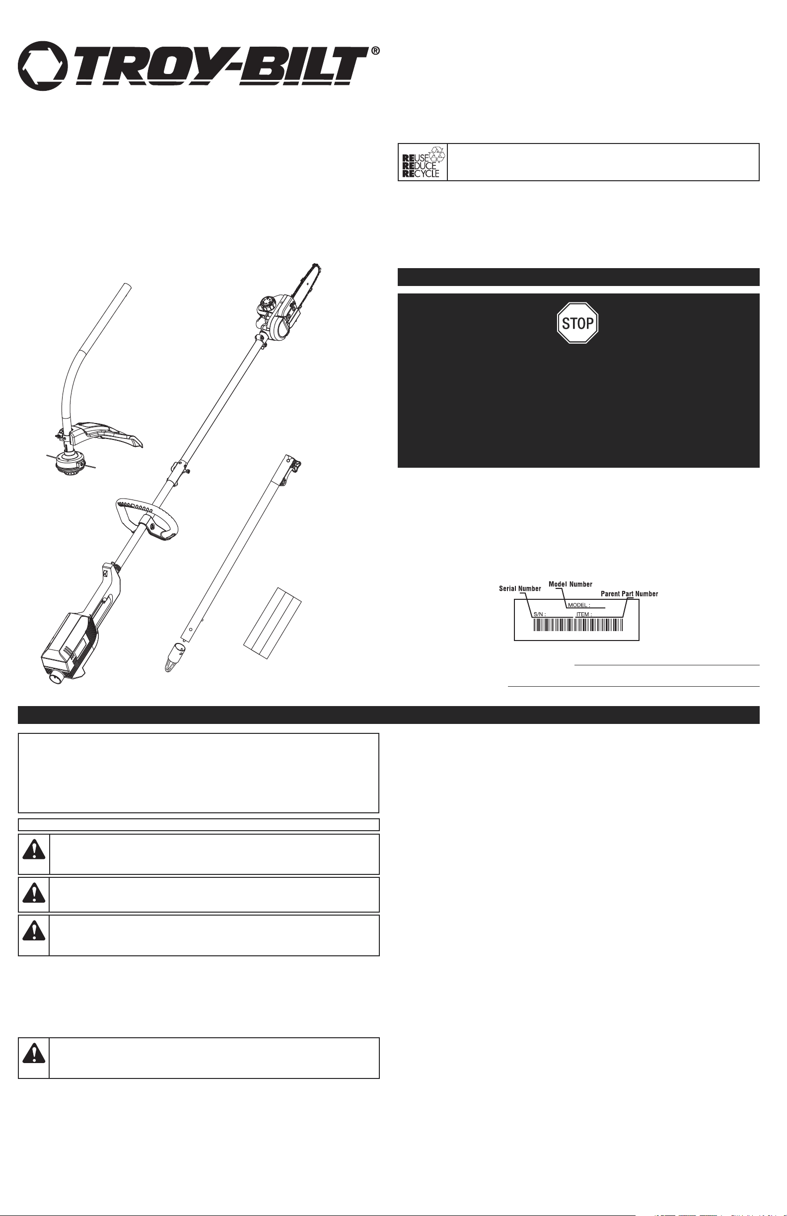
Electric Pole Saw / Trimmer
TB138PS
TABLE OF CONTENTS
Service Information . . . . . . . . . . . . . . . . . . . . . . . . . . . . . . . . . . . . . . . . . . . . . . . . . . . . . . . . . . . . . .1
Safety Information . . . . . . . . . . . . . . . . . . . . . . . . . . . . . . . . . . . . . . . . . . . . . . . . . . . . . . . . . . . . . . .1
Know Your Unit . . . . . . . . . . . . . . . . . . . . . . . . . . . . . . . . . . . . . . . . . . . . . . . . . . . . . . . . . . . . . . . . .3
Assembly Instructions . . . . . . . . . . . . . . . . . . . . . . . . . . . . . . . . . . . . . . . . . . . . . . . . . . . . . . . . . . . .4
Starting and Stopping Instructions . . . . . . . . . . . . . . . . . . . . . . . . . . . . . . . . . . . . . . . . . . . . . . . . . .4
Operating Instructions . . . . . . . . . . . . . . . . . . . . . . . . . . . . . . . . . . . . . . . . . . . . . . . . . . . . . . . . . . .4
Maintenance and Repair Instructions . . . . . . . . . . . . . . . . . . . . . . . . . . . . . . . . . . . . . . . . . . . . . . . .5
Cleaning and Storage . . . . . . . . . . . . . . . . . . . . . . . . . . . . . . . . . . . . . . . . . . . . . . . . . . . . . . . . . . . .7
Troubleshooting . . . . . . . . . . . . . . . . . . . . . . . . . . . . . . . . . . . . . . . . . . . . . . . . . . . . . . . . . . . . . . . .7
Specifications . . . . . . . . . . . . . . . . . . . . . . . . . . . . . . . . . . . . . . . . . . . . . . . . . . . . . . . . . . . . . . . . . .7
Warranty Information . . . . . . . . . . . . . . . . . . . . . . . . . . . . . . . . . . . . . . . . . . . . . . . . . . . . . . . . . . .E8
DO NOT RETURN THIS UNIT TO THE RETAILER. PROOF OF PURCHASE WILL BE REQUIRED
FOR WARRANTY SERVICE.
THIS PRODUCT IS COVERED BY ONE OR MORE U.S. PATENTS. OTHER PATENTS PENDING.
For assistance regarding the assembly, controls, operation or maintenance of the unit, please call the
Customer Support Department. Additional information about the unit can be found on our website.
For service, please call the Customer Support Department to obtain a list of authorized service dealers near
you. Service on this unit, both within and after the warranty period, should only be performed by an
authorized and approved service dealer. When servicing, use only identical replacement parts.
Before beginning, locate the unit’s model plate, which lists the model and serial numbers of your unit.
Refer to the sample plate below and copy the information for future reference.
Copy the serial number here:
Copy the model and parent part numbers here:
DO NOT RETURN THIS
PRODUCT
Please call the Customer Support Department
or visit our website for assistance:
or
DANGER:Signals an EXTREME hazard.
Failure to obey a safety DANGER signal WILL result in serious injury or death to yourself or
to others.
WARNING:Signals a SERIOUS hazard.
Failure to obey a safety WARNING signal CAN result in serious injury to yourself or to others.
CAUTION:Signals a MODERATE hazard.
Failure to obey a safety CAUTION signal MAY result in property damage or injury to
yourself or to others.
IMPORTANT! Signals special mechanical information.
NOTE: Signals additional important general information.
SYMBOL MEANING
SAFETY INFORMATION
• SAFETY ALERT SYMBOLS •
Safety alert symbols are used to draw your attention to possible dangers. These symbols, and their
explanations, deserve your careful attention and understanding. The safety warnings do not by
themselves eliminate any danger. The instructions or warnings they give are not substitutes for
proper accident prevention measures. These safety instructions are not meant to cover every
possible condition that may occur. If questions arise, please call the Customer Support
Department at 1-800-828-5500 (U.S.) or 1-800-668-1238 (Canada).
SAVE THESE INSTRUCTIONS
All information, illustrations and specifications in this manual are based on the latest product information
available at the time of printing. We reserve the right to make changes at any time without notice.
Copyright© 2009 MTD SOUTHWEST INC, All Rights Reserved.
In an effort to reduce the impact on forests, and reduce carbon and greenhouse
gas emissions, MTD is using less paper by reducing the text size of this manual.
SERVICE INFORMATION
• Never allow children to operate the unit. Never allow adults to operate the unit without proper instruction.
• Make sure that all guards and safety attachments are properly installed before operating the unit.
• Keep these instructions. Refer to them often and use them to instruct other users. If loaning
someone this unit, also loan them these instructions.
• Keep bystanders, especially children and pets, at least 50 feet (15 m) away. If anyone enters the
work area, stop the unit!
• Keep the work area clean. Cluttered areas invite injuries. Do not start the operation until the work
area is clear and free from obstructions, there is secure footing and a planned retreat path from falling
branches.
• Always wear appropriate eye and ear/hearing protection when operating this unit. Wear safety
goggles, or safety glasses with side shields, that are marked as meeting ANSI Z87.1-1989
standards. Failure to do so could result in serious eye injury caused by thrown objects. If the
operation is dusty, wear a facemask or dust mask. When operating the unit over the head as a pole
saw, use a hardhat or other type of safety helmet.
• Dress appropriately. Wear non-slip protective gloves and boots. Do not wear loose clothing, jewelry,
short pants, sandals or go barefoot. Secure hair above shoulder level to prevent entanglement in
moving parts.
• Only use the unit in daylight or good artificial light.
• Only use the unit for its intended purpose. Only use the unit as described in this manual.
• Only use the manufacturer’s recommended attachments with this unit. The curved shaft trimmer
and pole saw Add-Ons have been evaluated by Underwriters Laboratories Inc. for use with this
unit; the use of any other accessory or attachment may increase the risk of injury.
TRIMMER SAFETY PRECAUTIONS
• Inspect the work area before using the unit. Remove any hard and/or sharp objects, such as metal,
glass, wire, etc. If thrown, such objects could cause property damage or injury to the operator or
bystanders.
• Only use 0.080 inch (2.03 mm) diameter original equipment manufacturer replacement line. Never
use metal-reinforced line, wire or rope. These can break off and become dangerous projectiles.
• This unit was not designed to be used as a brushcutter. Do not attach or operate this unit with any
type of brushcutting blade or brushcutting attachment.
• Keep the unit clean of vegetation and other materials. They may become lodged between the
cutting attachment and the shield.
• The cutting attachment shield must always be in place while operating the unit as a trimmer. Do not
operate the unit without both trimming lines extended and the proper line installed. Do not extend
the trimming line beyond the length of the shield.
• Extra caution is required when using the unit for edging purposes. There is an increased risk of
injury or property damage caused by thrown objects when the cutting attachment shield is not held
horizontal to the ground.
READ ALL INSTRUCTIONS BEFORE OPERATING
BASIC SAFETY PRECAUTIONS
• DO NOT rely exclusively upon the safety devices built into the unit.
• DO NOT allow the unit to be used as a toy.
• Please read the entire operator’s manual carefully before attempting to assemble, operate or
maintain the unit.
• Follow all safety instructions. Failure to do so can result in property damage or serious injury to
yourself and/or others.
• Be thoroughly familiar with the controls and the proper use of the unit. Know how to stop the unit
and disengage the controls quickly.
• Stay alert! Do not operate the unit when tired, ill or under the influence of alcohol, drugs or medication.
WARNING:
When using an electric unit, basic safety precautions should
always be followed to reduce the risk of fire, electric shock and injury to persons, including
the following.
U.S.
1-800-828-5500
www.troybilt.com
Canada
1-800-668-1238
www.troybilt.ca
Page 2
SAFETY INFORMATION
2
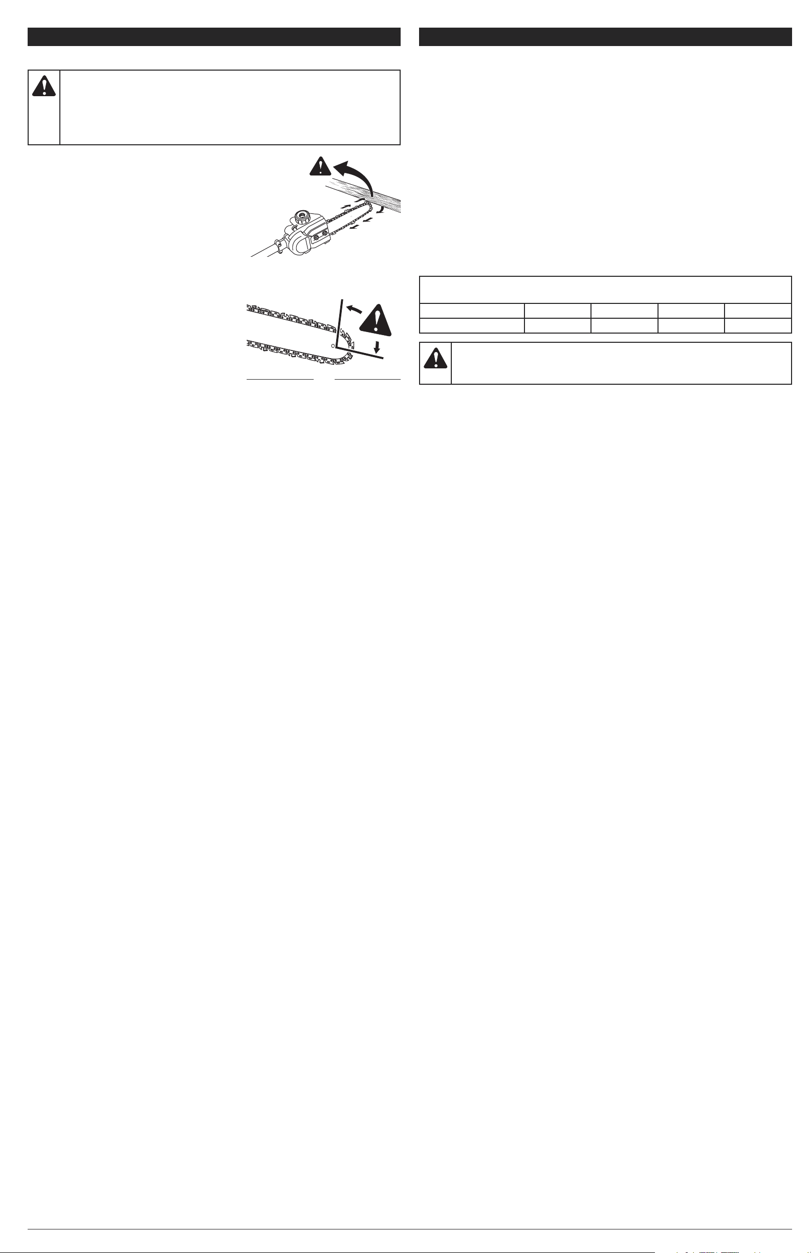
UNDERSTANDING KICKBACK
• Rotational Kickback can happen when the upper tip of
the guide bar contacts an object while the chain is
moving (Fig. 1 & 2). This can cause the chain to dig into
the object and momentarily stop moving. The guide bar
is then kicked up and back toward the operator in a
lightning-fast reverse reaction.
• Pinch Kickback can happen when the wood on either
side of a cut closes in and pinches the moving saw chain
along the top of the guide bar. This can cause the chain
to instantly stop. The chain force is then reversed,
causing the saw to move in the opposite direction,
sending the saw straight back toward the operator.
• Pull-In can happen when the moving chain on the bottom
of the guide bar hits a foreign object inside the wood. This
can cause the chain to suddenly stop. The saw is then
pulled forward and away from the operator, which could
potentially result in the loss of control of the saw.
KICKBACK SAFETY PRECAUTIONS
• DO NOT make cuts with the tip of the guide bar (Fig. 1).
• DO NOT let the tip of the guide bar contact any object,
such as a log, branch, ground or other obstruction.
Remove or avoid any obstructions that might impact the
tip of the guide bar while cutting.
• DO NOT cut more than one branch at a time.
• DO NOT twist the saw when removing the guide bar
from an undercut.
• Stand slightly to the left of the unit to avoid being in the direct line of the saw chain. Follow all the
Proper Grip on Handles instructions in the Operating Instructions section.
• Never start the saw when the guide bar is inside an existing cut. Be extremely careful when reentering a cut.
• Always begin a cut with the motor running at full speed. Fully squeeze the switch trigger and
maintain a steady cutting speed. Slower speeds increase the chance of kickback. Keep the saw
housing pressed firmly against the wood.
• Watch for shifting logs, branches, or other objects that might pinch, or fall onto, the chain while cutting.
• If using wedges, only use wedges made of plastic or wood. Do not use metal to hold a cut open.
• Follow the manufacturer’s sharpening and maintenance instructions for the saw chain.
• Only use replacement bars and chains specified by the manufacturer or the equivalent. These are
available from authorized service dealers. Use of any unauthorized parts or accessories could lead
to serious injury to the operator or damage to the unit and will void the warranty.
• Use devices, such as low-kickback chains, guide bar nose guards, chain brakes and special guide
bars, which reduce the risks associated with kickback. There are no other replacement
components for achieving kickback protection in accordance with CSA Z62.3.
•
Low-kickback saw chain is chain that has met the kickback performance requirements of ANSI
B175.1-1991 and is in accordance with CSA Z62.3. Do not use a replacement chain unless it has met
these requirements for the specific model. As saw chains are sharpened, some of the low kickback
qualities are lost and extra caution should be used.
POLE SAW SAFETY PRECAUTIONS
• DO NOT cut near electrical cables or power lines.
• DO NOT use a pole saw to fell a tree. Use a standard chain saw for this application.
• When cutting a limb that is under tension, be alert for spring back, which may cause the operator to
be struck when the tension of the wood fibers is released.
• Use extreme caution when cutting small-sized brush and saplings, as slender material may catch
the saw chain and be whipped toward the operator or pull the operator off balance.
• This saw is classified by UL as a Class 2C saw. It is intended for infrequent use by homeowners,
cottagers and campers, and for general applications such as clearing, pruning, cutting firewood,
etc. It is not intended for prolonged use. If the intended use involves prolonged periods of
operation, this may cause circulatory problems in the user’s hands due to vibration. It may be
appropriate to use a saw having an anti-vibration feature.
GENERAL SAFETY PRECAUTIONS
• DO NOT handle the unit, plug or cord with wet hands.
• DO NOT over reach.
• DO NOT
operate the unit on unstable surfaces, such as in trees or on ladders, slopes or rooftops.
Be very careful when using the unit on stairs.
• DO NOT expose the unit to rain. Do not use the unit in damp or wet locations or conditions.
• DO NOT
operate the unit on wet surfaces.
• DO NOT use the unit in the presence of flammable liquids or gases.
• DO NOT operate a unit that is damaged, improperly adjusted or not completely and securely
assembled. Be sure that the unit stops when the trigger is released. Do not use the unit if the
trigger does not turn the unit on and off properly. Have defective triggers replaced by an authorized
service center.
• DO NOT attempt operations beyond the operator’s capacity or experience.
• DO NOT operate the unit with one hand! Serious injury to the operator, helpers or bystanders may
result from one-handed operation. This unit is intended for two-handed use. Grip the unit firmly with
both hands when the motor is running. Keep the left hand on the D-handle and the right hand on
the shaft grip. Use a firm grip with thumbs and fingers encircling the handles. Do not let go!
• DO NOT force the unit. It will do a better, safer job when used at the intended rate.
• DO NOT leave the unit unattended while the unit is connected to the power source. Unplug the unit
from the power source when not in use.
• Adjust the D-handle to provide the best grip.
• Keep hair, loose clothing, fingers and all other body parts away from moving parts. Do not try to
touch or stop moving parts (cutting attachment or pole saw chain) when they rotate.
• Keep proper footing and balance at all times.
• Make sure the cutting attachment/pole saw chain is not in contact with anything before starting the unit.
• Always stop the motor when operation is delayed, before setting down the unit or when walking
from one location to another. Make sure the unit comes to a complete stop.
•
To avoid accidental starting, never carry the unit with fingers on the trigger.
• Always make sure the trigger is released before connecting or disconnecting the unit from the
power source.
•
Always carry the unit with both hands, with the unit disconnected from the power source and finger off
the trigger. When used as a pole saw, always carry the unit with the guide bar and chain sheathed in the
scabbard and positioned to the rear.
• If the unit strikes or becomes entangled with a foreign object, stop the motor immediately,
disconnect the unit from the power source and check for damage. Do not restart or operate the unit
before repairing damage.
SAFETY INFORMATION
ELECTRICAL SAFETY PRECAUTIONS
• DO NOT abuse the extension cord. Never pull or carry the unit by the cord, use the cord as a
handle, close a door on a cord, pull the cord around sharp edges or corners or yank the cord to
disconnect the unit. Grasp the plug, not the cord, to disconnect the unit.
• DO NOT modify the extension cord, plug or wall outlet in any way.
• DO NOT use multiple extension cords.
• Keep the cord away from oil, water, sharp objects and heated surfaces.
• Keep the cord away from the cutting area and position the cord so that it will not be caught on
branches or other obstacles that may bind or entangle the cord during operation.
• Keep the cord away from the operator’s feet to prevent tripping.
• Make sure the cord is in good condition. Inspect the extension cord periodically. Look closely for
deterioration, cuts or cracks in the insulation. If the extension cord is damaged, replace it. Do not
use a damaged cord or plug.
• If the extension cord is damaged in any manner while plugged in, disconnect the extension cord
from the receptacle.
• Since the unit is double-insulated, a 2-wire extension cord (one without a ground) may be used.
However, a 3-wire extension cord (one with a ground) that uses a NEMA-type connector (parallel
blade, U ground) is recommended. Extension cords are available from local retailers. Use only
round-jacketed extension cords approved for outdoor use.
• Make sure the extension cord is heavy enough to carry the current drawn by the unit. An
undersized cord will cause a drop in line voltage resulting in loss of power and overheating. If in
doubt, use the next heavier gauge cord. The smaller the gauge number, the heavier the cord.
• To reduce the risk of electrical shock, this unit has a polarized plug (one blade is wider than the
other) and will require the use of a polarized extension cord. The recessed plug will fit into a
polarized extension cord only one way. If the plug does not fit fully into the extension cord, reverse
the plug. If the plug still does not fit, obtain another polarized extension cord. A polarized extension
cord will require the use of a polarized wall outlet. This plug will fit into the polarized wall outlet only
one way. If the plug does not fit fully into the wall outlet, reverse the plug. If the plug still does not
fit, contact a qualified electrician to install the proper wall outlet.
• A nameplate on your unit indicates the voltage used. Never connect the unit to an AC voltage that
differs from this voltage.
• Ground Fault Circuit Interrupter (GFCI) protection should be provided on the circuit(s) or outlet(s) that
will be used with the unit. For an extra measure of safety, use receptacles with built-in GFCI protection.
• To reduce the likelihood of disconnecting the extension cord from the unit, be sure to use the cord
retainer provided.
• To reduce the risk of electric shock, avoid body contact with grounded conductors, such as metal
pipes or wire fences.
SERVICING A DOUBLE-INSULATED UNIT
• This is a double-insulated unit. Two systems of insulation are provided instead of grounding. There is
no grounding provided and no means of grounding should be added to the unit. Servicing a doubleinsulated unit requires extreme care and knowledge of the system and should only be done by
qualified service personnel. Replacement parts for a double-insulated unit must be identical to the
parts they replace. Failure to have a double-insulated unit repaired by an authorized service
technician with identical replacement parts could result in serious injury.
MAINTENANCE AND STORAGE SAFETY
• If the unit is not working as it should, has been dropped, damaged, left outdoors or dropped into
water, do not use the unit. Have the unit serviced by an authorized service center.
• All service, other than the maintenance procedures described in this manual, should be performed
by an authorized service center. Do not attempt to repair; there are no user serviceable parts inside.
• Follow all maintenance instructions in this manual.
• Before inspecting, servicing, cleaning, storing, transporting, replacing parts or changing
accessories on the unit:
1. Stop the motor. Make sure the trigger is released.
2. Make sure all moving parts have stopped.
3. Disconnect the unit from the power source.
4. Allow the unit to cool.
• Never remove, modify or make inoperative any safety device furnished with the unit.
• For safer, more effective performance, make sure the bar and chain are properly cleaned, lubricated,
tightened and sharpened. Check the bar and chain at frequent intervals for proper adjustment.
• Frequently inspect the unit for damage. Before further use, any damaged part should be carefully
checked to determine that it will operate properly and perform its intended function. Check for
alignment of moving parts, binding of moving parts, breakage of parts and any other conditions
that may affect its operation. Damaged parts should be properly repaired or replaced by an
authorized service center, unless otherwise indicated in this manual.
• If the unit starts to vibrate abnormally, stop the motor, disconnect the unit from the power source and
allow the unit to cool. Then inspect the unit for the cause of the vibration. Vibration is generally an
indicator of trouble.
• Use only original manufacturer replacement parts and accessories, which are designed specifically to
enhance the performance and maximize the safe operation of the product. Failure to do so may cause
poor performance and possible injury. Use only the chain and guide bar supplied with this product.
• Be sure to secure the unit while transporting.
• Always use the scabbard on the bar and chain during transportation and storage.
• When not in use, store the unit indoors in a locked-up and dry, or high and dry, place to prevent
unauthorized use or damage. Keep out of the reach of children.
•
Keep the handles dry, clean and free from debris, oil and grease. Clean the unit after each use. Never
douse or spray the unit with water or any other liquid. Do not wash the unit with a hose; avoid getting
water in the motor and electrical connections.
Do not use solvents or strong detergents.
Fig. 2
Kickback Danger Zone
Fig. 1
Rotational
Kickback
MINIMUM WIRE SIZE FOR EXTENSION CORDS
FOR 120 VOLT APPLIANCES USING 0-12 AMPS
CORD LENGTH (FEET) 25 50 100 150
WIRE SIZE (AWG) 16 16 14 12
WARNING:To reduce the risk of electric shock, only use extension cords
suitable for outdoor use, such as SW-A, SOW-A, STW-A, STOW-A, SJW-A, SJOW-A,
SJTW-A or SJTOW-A cord types.
DANGER:Kickback may occur when the nose or tip of the guide bar touches
an object, or when the wood closes in and pinches the saw chain in the cut. In some cases,
tip contact may cause a lightening-fast reverse action, kicking the guide bar rapidly back
towards the operator. Pinching the saw chain along the top of the guide bar may push the
guide bar rapidly back towards the operator. Either of these reactions may cause a loss of
control over the saw, which could result in serious injury to the user. Contact with foreign
objects within the wood can also induce a loss of chain saw control.
Page 3
3
• SAFETY AND INTERNATIONAL SYMBOLS •
This operator's manual describes safety and international symbols and pictographs that may appear
on this product. Read the operator's manual for complete safety, assembly, operating, maintenance
and repair information.
• SAFETY ALERT SYMBOL
Indicates danger, warning or caution. May be used in conjunction with other symbols
or pictographs.
• READ OPERATOR'S MANUAL
WARNING:
Read the operator’s manual(s) and follow all warnings and
safety instructions. Failure to do so can result in serious injury to the operator and/or
bystanders.
• WEAR HEAD, EYE AND HEARING PROTECTION
WARNING:
Thrown objects and loud noise can cause severe eye injury
and hearing loss. Wear eye protection meeting ANSI Z87.1-1989 standards and ear
protection when operating this unit. Wear head protection when operating this unit;
falling objects can cause severe head injury. Use a full face shield when needed.
SYMBOL MEANING
• DO NOT USE IN THE RAIN
WARNING:
Avoid dangerous environments. Never operate your unit in
the rain, or in damp or wet conditions. Moisture is a shock hazard.
SAVE THESE INSTRUCTIONS
• THROWN OBJECTS AND ROTATING CUTTER CAN CAUSE SEVERE INJURY
WARNING:
Small objects can be propelled at high speed, causing
injury. Keep away from the rotating cutter.
• WEAR SAFETY FOOTWEAR
Wear non-slip safety footwear when using this equipment.
• WEAR SAFETY GLOVES
Wear non-slip, heavy-duty protective gloves when handling the unit.
• DOUBLE INSULATED
Two systems of insulation are provided instead of grounding. There is no grounding
provided and no means of grounding should be added to the unit.
• SHARP BLADE
WARNING:
There is a sharp blade on the cutting attachment shield. To
prevent serious injury, do not touch the line cutting blade.
SAFETY INFORMATION
• KEEP BYSTANDERS AWAY
WARNING:
Keep all bystanders, especially children and pets, at least
50 feet (15 m) from the operating area. If anyone enters the work area, stop the unit!
• POWER LINES CAN CAUSE SEVERE INJURY
DANGER:
Do not operate this unit near power lines. Contact with a
power line may cause serious injury or damage to the unit. Maintain a clearance of at
least 50 feet (15 m) between the pole saw (including any branches it is contacting) and
any electrical line.
WARNING:Always keep a clear work area and retreat path. Be aware
of the location of limbs/branches to avoid falling limbs and debris.
• KICKBACK WARNING
Contact of the guide bar tip with any object should be avoided. Tip contact may cause
the guide bar to move suddenly upward and backward, which may cause serious injury.
• USE BOTH HANDS
Always use both hands while operating the pole saw. Never use only one hand to
operate the unit.
• THROTTLE CONTROL
Indicates “IDLE,” “LOW” or “SLOWEST” speed.
• THROTTLE CONTROL
Indicates “HIGH” or “FASTEST” speed.
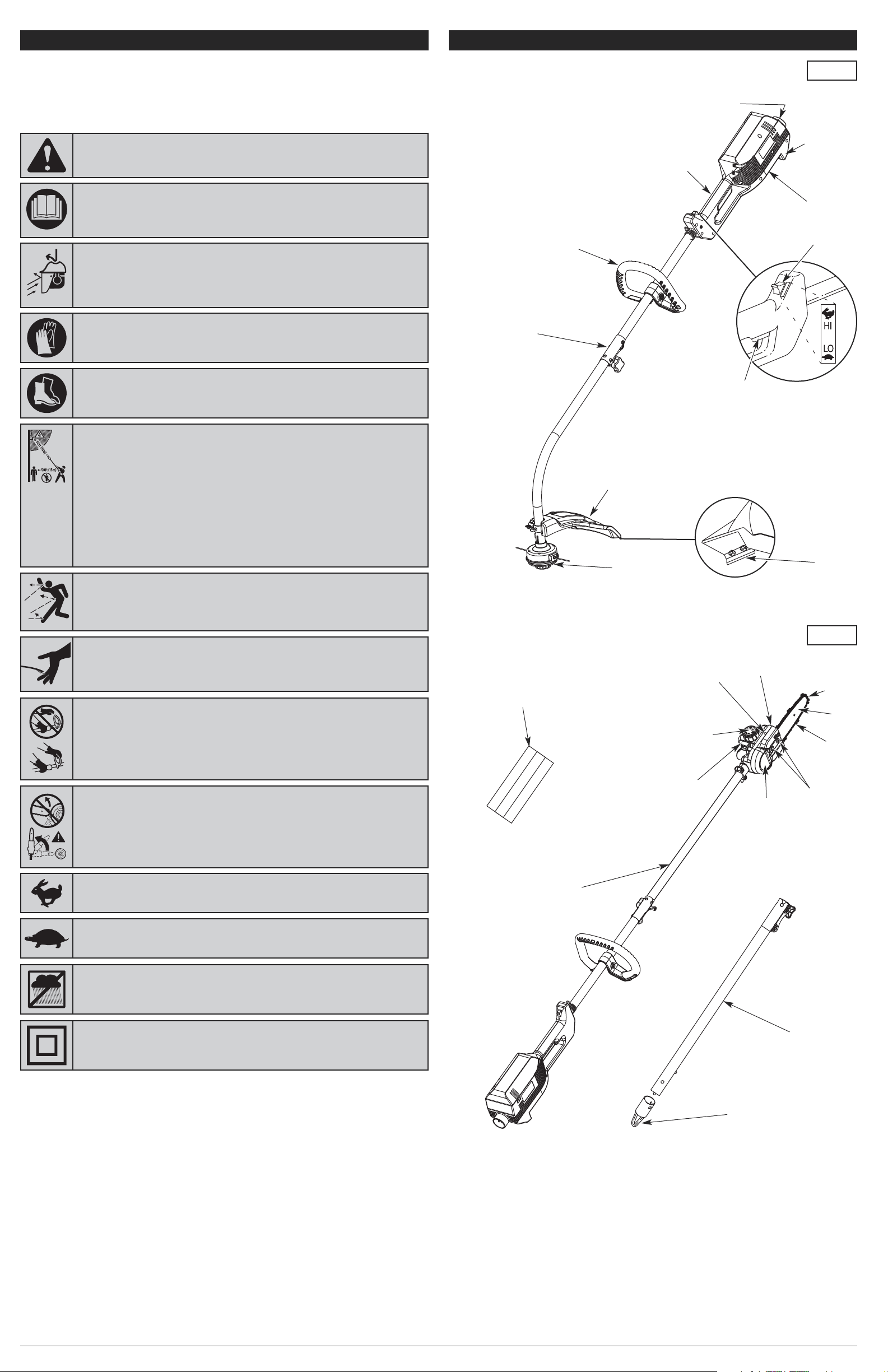
KNOW YOUR UNIT
Cutting
Attachment
Shield
Motor
Housing
APPLICATIONS
This unit may be used for the purposes listed below:
As a trimmer:
• Cutting grass and light weeds
• Decorative trimming around trees, fences, etc.
As a pole saw:
• Cutting small limbs
• General tree pruning
Other optional accessories, which have not been
evaluated by Underwriters Laboratories Inc., may be
used with this unit, as specified in this manual. Refer
to The EZ-Link
TM
System for a list of Add-Ons.
D-Handle
Trigger
Low Kickback
Saw Chain
Guide
Bar Tip
Guide
Bar
Cutting
Line Blade
Scabbard
Trimmer
Conversion
Pole Saw
Conversion
Shaft
Grip
Two-speed Switch
Cord Retainer
(not shown)
Cutting
Attachment
Recessed Plug
Bar
Cover
Bar
Retaining
Nuts
Bar Lube
Reservoir Cap
Bar Lube
Adjustment Screw
Drive Shaft
Extension Boom
EZ-Link
TM
Coupler
Hanger
Bar Lube
Reservoir
Chain-tensioning
Screw
Page 4
Testing the EZ-LinkTMCoupler Connection
After assembling an Add-On, always test the unit:
1. Start the motor. See Starting and Stopping Instructions.
2. Briefly engage and release the trigger.
3. Make sure the Add-On operates. If not, remove and reinstall the Add-On (and extension boom, if
used).
4. Repeat these instructions until the Add-On operates.
CONNECTING AND DISCONNECTING THE POWER SOURCE
Follow these instructions in order to avoid injury and to reduce the risk of electric shock or fire:
• Verify that the trigger is released and the motor is off before connecting or disconnecting the power
source. Refer to Starting and Stopping Instructions.
• Verify that the motor is off and the unit is disconnected from the power source before inspecting,
adjusting or performing maintenance on any part of the unit.
Only use outdoor-approved extension cords. Cord sets are specified in the Important Safety
Information section.
Connecting the Power Source
1. Make a narrow loop with the extension cord and push
the loop through the lower opening in the cord retainer
(Fig. 12).
2. Move the loop onto the cord hook and pull the cord
gently to secure the loop over the hook (Fig. 12). This
helps prevent accidental disconnection.
3. Connect the extension cord to the recessed plug on the
unit (Fig. 12)
4. Connect the extension cord plug to the outlet.
Disconnecting the Power Source
1. Disconnect the extension cord plug from the outlet.
2. Remove the loop in the extension cord from the cord hook.
3. Disconnect the extension cord from the recessed plug on the unit (Fig. 12).
4
This unit requires assembly.
UNPACKING
• Carefully remove the product and any accessories from
the box.
• Inspect the product carefully to make sure no breakage
or damage occurred during shipping.
• Do not discard the packing material until you have carefully
inspected and satisfactorily operated the product.
• If any parts are damaged or missing, please call 1-800-828-
5500 (U.S.) or 1-800-668-1238 (Canada) for assistance.
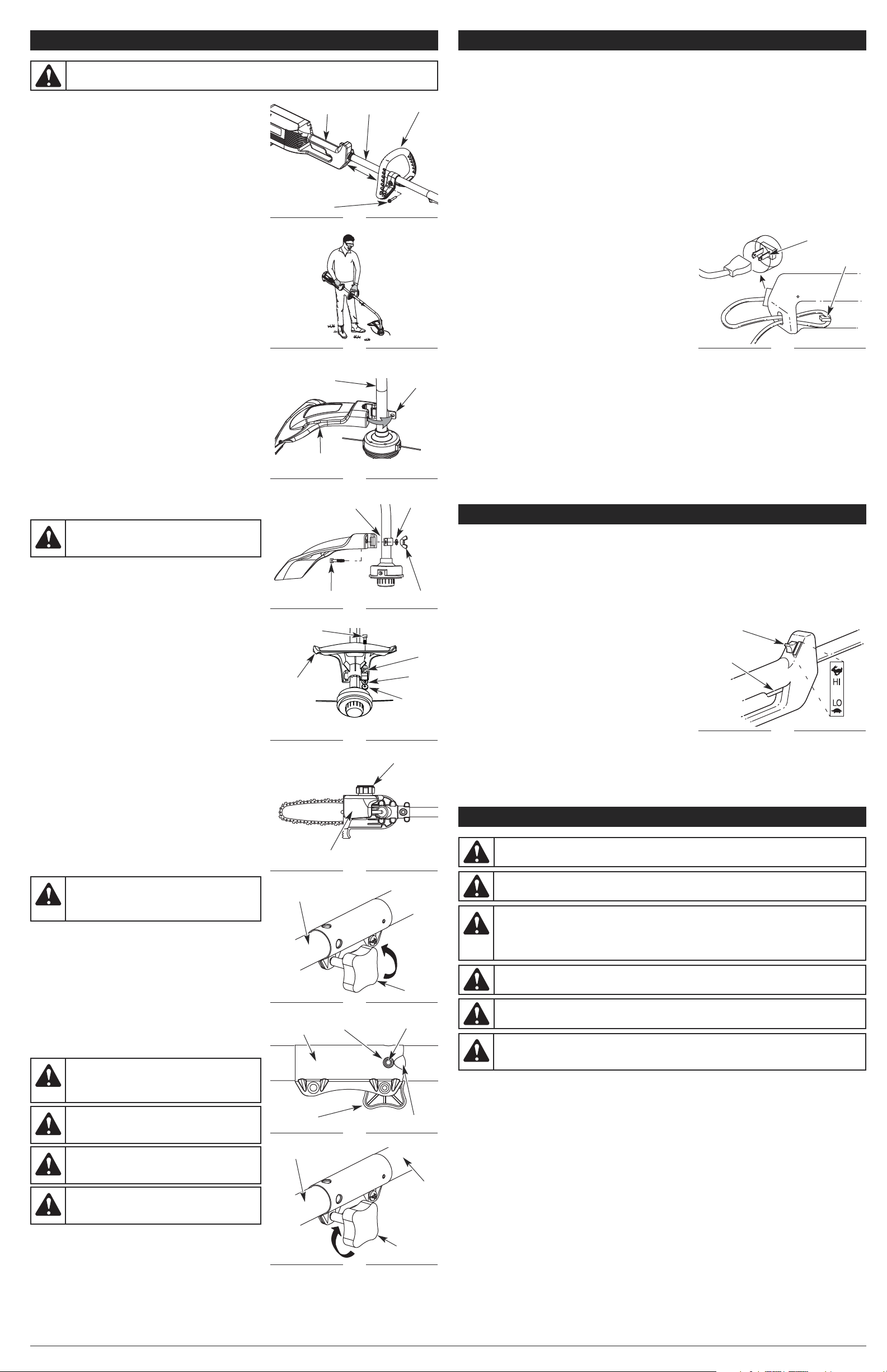
INSTALLING AND ADJUSTING THE D-HANDLE
1. Push the D-handle down onto the shaft (Fig. 3). The
clamp bolt hole in the D-handle is to the right.
2. Insert the clamp bolt into the hole in the D-handle and
partially tighten the clamp bolt. Do not tighten the clamp
bolt completely until you make the D-handle adjustment.
3. While holding the unit in the operating position (Fig. 4),
move the D-handle to the location that provides you the
best grip. Place it a minimum of 6 inches (15.24 cm)
from the base of the shaft grip.
4. Tighten the clamp bolt until the D-handle is secure.
TRIMMER ASSEMBLY: INSTALLING THE CUTTING
ATTACHMENT SHIELD
Use the following instructions if the cutting attachment
shield is not installed on the unit:
1. Place the cutting attachment shield onto the shaft
housing. Be sure the guard mounting bracket slides into
the slot on the edge of the cutting shield. Rotate the
shield into place, counterclockwise. The holes in the
guard mounting bracket and cutting attachment shield
will line up (Fig. 5).
2. From inside the cutting attachment shield, push the
square bolt through the hole until the threaded end
protrudes through the guard mounting bracket (Fig. 6).
3. Put the washer on the bolt, then screw the wing nut onto
the bolt and tighten. Figure 7 shows the installation
process from underneath the unit.
POLE SAW ASSEMBLY: ADDING BAR AND CHAIN
LUBRICANT
Only use bar and chain oil that is formulated to perform
over a wide range of temperatures with no diluting required
in the oil reservoir. Do not use motor oil or any other
petroleum-based oil.
NOTE: This pole saw comes from the factory with the
bar lube reservoir empty. Use the bottle of bar
and chain oil that is included with the unit.
1. Remove the bar lube reservoir cap (Fig. 8).
2. Carefully pour the bar and chain oil into the bar lube
reservoir until the reservoir is filled.
3. Replace the bar lube reservoir cap and tighten securely.
4. Wipe off excess oil.
5. The unit is ready for use.
NOTE: Because bar lube reservoirs are designed to keep
oil slowly flowing onto the chain, be sure to check
the oil level after every 15 minutes of operation
and refill the bar lube reservoir as needed. Also
see the Chain Lubrication instructions in the
Maintenance and Repair Instructions section.
NOTE: Do not use dirty, used or otherwise contaminated
oils. Damage may occur to the guide bar or chain.
NOTE: The bar lube reservoir can be filled to the lip of the
fill opening without damaging the unit.
IMPORTANT! Please dispose of oil properly. Consult your
local waste authority for information regarding
available disposal options.
EZ-LINK
TM
COUPLER ASSEMBLY
The EZ-Link
TM
coupler allows the unit to use various Add-
Ons. Refer to The EZ-Link
TM
System.
Installing the Add-Ons or Extension Boom
NOTE: To make installation easier, place the unit on the
ground or on a workbench.
1. Turn the knob counterclockwise to loosen the EZ-Link
TM
coupler (Fig. 9).
2. While firmly holding the Add-On or extension boom, align
the release button with the guide recess (Fig. 10) and push
the Add-On or extension boom straight into the EZ-Link
TM
coupler until the release button (Fig. 10) snaps into the
primary hole (Fig. 10). The primary hole is on the opposite
side of the coupler from the knob (Fig. 10).
3. Turn the knob clockwise to tighten (Fig. 11).
Removing the Attachments or Extension Boom
1. Turn the knob counterclockwise to loosen the EZ-Link
TM
coupler (Fig. 9).
2. Press and hold the release button.
3. While firmly holding the upper shaft boom (Fig. 11), pull the Add-On or extension boom out of the
EZ-Link
TM
coupler.
Fig. 3
Shaft Grip
D-Handle
STARTING AND STOPPING INSTRUCTIONS
This unit is equipped with a two-speed switch. The switch has a powerful high speed for demanding
yard work and a precision low speed for light-duty yard work.
STARTING THE MOTOR
When used as a pole saw, make sure the chain tension is at the desired setting prior to starting the
motor. Refer to Adjusting the Chain Tension in the Maintenance and Repair section. Also make sure
the bar retaining nuts are tight to the bar cover.
Make sure the immediate area is clear of any objects or obstructions that could come in contact with
the cutting attachment or guide bar and chain.
1. Connect the unit to the power source. Refer to
Connecting and Disconnecting the Power Source.
2. Squeeze the trigger to start the unit (Fig. 13).
3. Push the two-speed switch up to the “HI” position for
high speed or push the switch down to the “LO” position
for low speed (Fig. 13).
STOPPING THE MOTOR
1. Release the trigger (Fig. 13).
NOTE: When used as a pole saw, it is normal for the chain
to coast to a stop once the trigger is released.
Fig. 13
WARNING:
Make sure the motor is off and the unit is disconnected from the power
source before assembling or disassembling any components.
Fig. 5
Shaft
Housing
Guard
Mounting
Bracket
PROPER GRIP ON HANDLE
• Always maintain a proper grip on the handles whenever the motor is running. Grip the unit firmly
with both hands. Keep the left hand on the D-handle and the right hand on the shaft grip. The
fingers should encircle the handle(s) and the thumb(s) should wrap under the handle(s). The left arm
should be straight and the right arm slightly bent.
PROPER STANCE
• Balance body weight securely, with both feet on solid ground.
• When used as a pole saw, keep the left arm locked in a “straight arm” position to withstand any
kickback force.
WORK AREA PRECAUTIONS
• Keep everyone – helpers, bystanders, children and animals – at least 50 feet (15 m) away from the
work area. If anyone enters the work area, stop the unit!
• Only operate the unit when visibility and light are adequate to see clearly.
• Remove stones, nails, glass and wire from the area before operating the unit.
• To reduce noise levels, operate the unit at the lowest speed needed to do the job.
• Only operate the unit during reasonable hours. Comply with times listed in local ordinances.
OPERATING INSTRUCTIONS
WARNING:
Do not allow familiarity with this unit to promote carelessness. Remember
that a careless fraction of a second is enough to inflict serious injury.
WARNING:
Always wear appropriate eye and ear/hearing protection when operating this
unit. Wear safety goggles, or safety glasses with side shields, that are marked as meeting
ANSI Z87.1-1989 standards. Failure to do so could result in serious eye injury caused by
thrown objects. If the operation is dusty, wear a facemask or dust mask. When operating
the unit as a pole saw over the head, use a hardhat or other type of safety helmet.
WARNING:
If any parts are damaged or missing, do not operate the unit until the parts
are replaced. Failure to heed this warning could result in serious personal injury.
WARNING:
Wear non-slip gloves for maximum grip and protection. Refer to the Safety
Information section for appropriate safety equipment.
WARNING:
Do not expose the unit to rain. Do not use the unit in damp or wet locations
or conditions.
Two-speed
Switch
Shaft
Clamp Bolt
Minimum
6 inches
(15.24 cm)
Fig. 8
Fig. 6
Guard Mounting
Bracket
Washer
Fig. 7
Square Bolt
Washer
Cutting Attachment
Shield
Square Bolt
Wing Nut
Cutting
Attachment
Shield
Wing Nut
Hole
Cutting Attachment: Underside View
WARNING:
Make sure the bar lube reservoir
is always filled. Failure to fill the bar lube reservoir
will cause irreparable damage to the unit.
Fig. 4
Fig. 12
Bar Lube Reservoir
Bar Lube Reservoir Cap
CAUTION:
Before operating the unit, make
sure the release button is fully snapped into the
primary hole (Fig. 10) and the knob is securely
tightened.
CAUTION:
Only snap Add-Ons into the
primary hole. Using other holes could result in
personal injury or damage to the unit.
Fig. 9
Fig. 10
Primary Hole
Knob
Fig. 11
Upper
Shaft
Boom
EZ-Link
TM
Coupler
EZ-Link
TM
Coupler
Release Button
Guide Recess
Attachment
Knob
WARNING:
To avoid serious personal injury
and damage to the unit, never install more than
one extension boom to this unit.
WARNING:
The extension boom is for pole
saw operation only. Do not install the extension
boom when the unit is used as a trimmer.
Trigger
ASSEMBLY INSTRUCTIONS ASSEMBLY INSTRUCTIONS
EZ-Link
TM
Coupler
Attachment
Knob
WARNING:
To avoid serious injury, do not wear loose fitting garments, such as scarves,
strings, chains or ties, which could be drawn into the air intake. Long hair must be pulled
back and secured at the shoulders and neck.
WARNING:
Before using any attachment,
read and understand the manual that came
with the attachment. Follow all safety
instructions contained within.
Cord Hook
Recessed Plug
Page 5
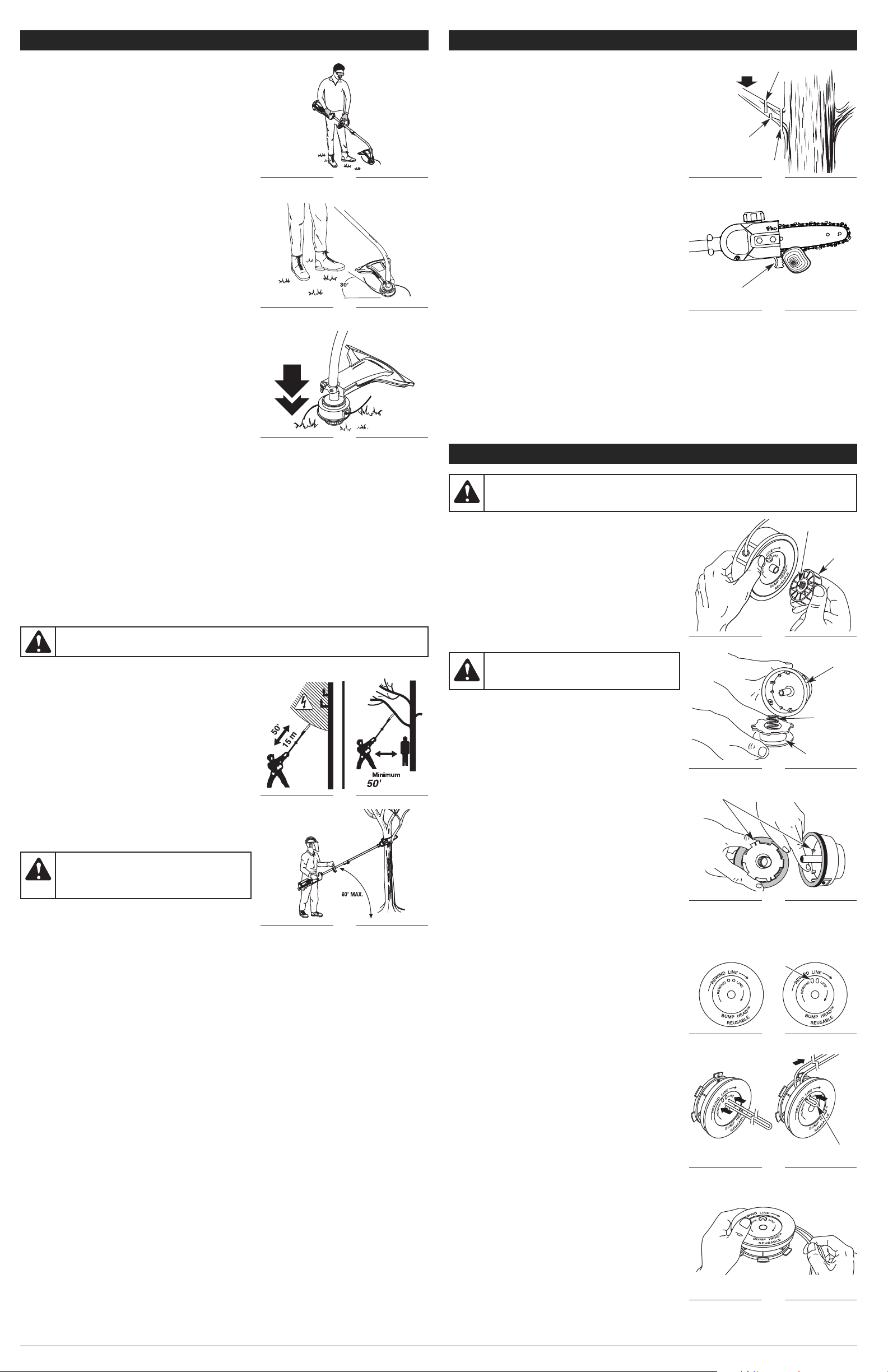
OPERATING THE UNIT AS A TRIMMER
1. Hold the unit at waist level with the cutting attachment
parallel to the ground so that it easily contacts the grass
without the need to bend over (Fig. 14).
2. Start the motor. Refer to Starting and Stopping Instructions.
3. Slowly move the cutting attachment into and out of the
cutting area at the desired height.
• Move either in a forward-backward or side-to-side
motion. When cutting from side-to-side, cut from right to
left whenever possible. This improves the unit’s cutting
efficiency and directs clippings away from the operator.
• Cutting shorter lengths produces the best results.
• Cut grass over 8 inches (200 mm) by working from top
to bottom in small increments to avoid premature line
wear or motor drag.
• Do not force the cutting attachment. Allow the tip of the
line to do the cutting, especially along walls. Cutting
with more than the tip will reduce cutting efficiency and
may overload the motor.
• Only trim when grass or weeds are dry.
4. Dispose of debris appropriately.
Decorative Trimming
Decorative trimming is the act of removing all vegetation
from around trees, posts, fences, etc. To accomplish it,
rotate the whole unit so that the cutting attachment is at a
30˚ angle to the ground (Fig. 15).
Adjusting the Trimming Line Length
The Bump Head
TM
cutting attachment allows the release of
trimming line without having to stop the motor. To release
more line, lightly tap the cutting attachment to the ground
(Fig. 16) while operating the unit at high speed.
NOTE: Always keep the trimming line fully extended.
Line release becomes more difficult when the
cutting line gets shorter.
Each time the head is bumped, about 1 inch (25.4 mm) of
trimming line releases. A blade in the cutting attachment
shield will cut the line to the proper length if any excess line
is released.
For best results, tap the bump knob on bare ground or hard soil. If you attempt a line release in tall
grass, the motor may stall.
NOTE: Do not rest the Bump Head
TM
on the ground while the unit is running.
Some line breakage will occur from:
• Entanglement with foreign matter
• Normal line fatigue
• Attempting to cut thick, stalky weeds
• Forcing the line into objects such as walls or fence posts
The life of the cutting line is dependent upon:
• Following these trimming instructions
• What vegetation is being cut
• Where vegetation is being cut
For example, the line will wear faster when trimming against a foundation wall than when trimming
around a tree.
OPERATING THE UNIT AS A POLE SAW
Preparation for Cutting
• To prevent electrocution, do not operate within 50 feet
(15 m) of overhead electrical lines (Fig. 17).
• Keep everyone – helpers, bystanders, children and
animals – at least 50 feet (15 m) away from the work area
(Fig. 17). If anyone enters the work area, stop the unit!
• Wear non-slip gloves for maximum grip and protection.
• Maintain a proper grip on the unit whenever the motor is
running. Hold the unit firmly with both hands. Firmly grip
the shaft grip with the right hand and the D-handle with
the left hand (Fig. 18).
• The operator should be to the left of the chain line. Never
use a left-handed (cross-handed) grip, or any stance that
places any body part across the chain line (Fig. 18).
• Never stand directly under the limb being cut.
Pruning
This unit is designed for trimming small branches and limbs
up to 4 inches (10 cm) in diameter. For best results, observe
the following precautions.
• Do not use the pole saw for cutting down trees.
• Plan the cut carefully. Be aware of the direction in which the branch will fall.
• Branches may fall in unexpected directions. Do not stand directly under the branch being cut (Fig. 18).
• Do not cut from a ladder; this is extremely dangerous. Leave this operation for professionals.
• The most typical cutting application is to position the unit at an angle of 60° or less, depending on
the specific situation (Fig. 18). As the angle of the pole saw shaft to the ground increases, the
difficulty of making the first cut (from the underside of the limb) increases.
• Remove long branches in several stages.
• Do not make the flush cut next to the main limb or trunk until the limb has been cut further out to
reduce the weight.
• Cut lower branches first to allow the top branches more room to fall.
• Work slowly, keeping both hands on the unit with a firm grip. Maintain secure footing and balance.
• Avoid kickback. Kickback can result in severe injury or death. See Understanding Kickback and
Kickback Safety Precautions in the Safety Instructions section.
• Keep the unit running the entire time while cutting, making sure to maintain a steady speed.
• Allow the chain to do the cutting; exert only light downward pressure. Forcing the cut could result in
damage to the guide bar, chain or motor.
• Release the trigger as soon as the cut is completed. Allow the chain to come to a complete stop.
Unnecessary wear may occur to the chain, bar and unit if the saw is run without a cutting load.
• Do not put pressure on the saw at the end of the cut.
5
Fig. 15
Fig. 17
OPERATING INSTRUCTIONS
Fig. 14
Fig. 16
WARNING:
Do not remove or alter the line cutting blade assembly. Excessive line length
will make the motor overheat. This may lead to serious personal injury or damage to the unit.
OPERATING INSTRUCTIONS
Basic Cutting Procedure
Follow the steps below to prevent stripping the bark from
the main member of the tree or shrub. Do not use a back-
and-forth sawing motion.
1. Start the motor and let the chain accelerate to full speed
before starting the cut. Refer to Starting and Stopping
Instructions.
2. Make a shallow first cut (1/4 of the limb’s diameter) on
the underside of the limb close to the main limb or trunk
(Fig. 19).
3. Make a second cut from the top side of the limb
outboard from the first cut. Continue the cut through the
limb until the limb separates from the tree. Be prepared
to balance the weight of the tool when the limb falls.
4. Make a final cut close to main limb or trunk.
NOTE: For second and final cuts (from the top of the
limb or branch), hold the front cutting guide
against the limb being cut (Fig. 20). This will help
steady the limb and make it easier to cut. Allow
the chain to do the cutting; only exert light
downward pressure. If the cut is forced, damage
to the bar, chain or motor may result.
5. Release the trigger as soon as the cut is completed.
Failure to follow proper cutting procedures will result in
the bar and chain binding and becoming pinched or
trapped in the limb. If this should happen:
• Stop the motor and disconnect the unit from the power source.
• If the limb can be reached from the ground, lift the limb while holding the saw. This should release
the “pinch” and free the saw.
• If the saw is still trapped, call a professional for assistance.
Fig. 18
Fig. 19
Fig. 20
Load
First Cut
1/4 Diameter
Cutting
Guide
Final Cut
Second Cut
WARNING:
Use caution when pruning heavy
branches. Falling branches can cause serious
injury. Always wear head protection, plan a safe
exit from the path of falling limbs and stay alert.
MAINTENANCE AND REPAIR INSTRUCTIONS
NOTE: If it is necessary to replace damaged or missing
parts, use only manufacturer suggested
replacement parts. The use of any other parts
may create a hazard or cause product damage
and will VOID the warranty.
TRIMMER MAINTENANCE AND REPAIR
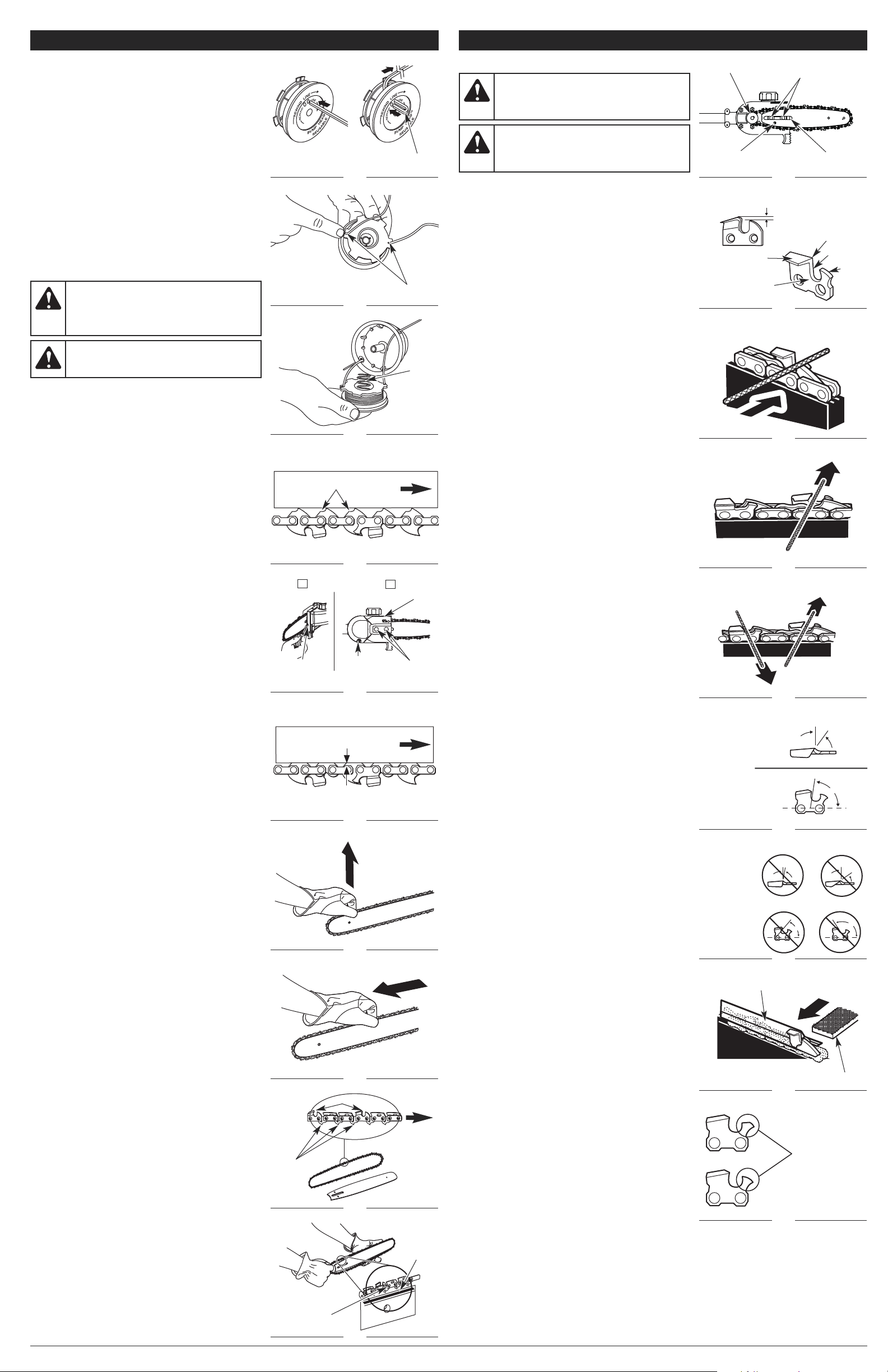
Line Installation
This section covers both SplitLine
TM
and standard single
line installation.
Always use original equipment manufacturer 0.080 in. (2.03
mm) replacement line. Line other than the specified may
make the motor overheat or fail.
There are two methods for replacing the trimming line:
• Wind the inner reel with new line
• Install a prewound inner reel
Winding New Line on the Existing Inner Reel
1. Hold the outer spool with one hand and unscrew the
bump knob counterclockwise (Fig. 21). Inspect the bolt
inside the bump knob to make sure it moves freely.
Replace the bump knob if damaged.
2. Remove the inner reel from the outer spool (Fig. 22).
3. Remove spring from the inner reel (Fig. 22).
4. Use a clean cloth to clean the inner reel, spring, shaft
and inner surface of the outer spool.
5. Check the indexing teeth on the inner reel and outer
spool for wear (Fig. 23). If necessary, remove burrs or
replace the reel and spool.
NOTE: SplitLine™ can only be used with the inner reel
with the slotted holes. Single line can be used on
either type of inner reel. Use Figure 24 to identify
the inner reel you have.
NOTE: Always use the correct line length when installing
trimming line on the unit. The line may not release
properly if the line is too long.
Single Line Installation
Go To Step 8 for SplitLine™ Installation
6. Take approximately 20 feet (6 m) of new trimming line,
loop it into two equal lengths. Insert each end of the line
through one of the two holes in the inner reel (Fig. 25).
Pull the line through the inner reel so that the loop is as
small as possible.
7. Wind the lines in tight even layers, onto the reel (Fig. 26).
Wind the line in the direction indicated on the inner reel.
Place your index finger between the two lines to stop
the lines from overlapping. Do not overlap the ends of
the line. Proceed to step 11.
SplitLine™ Installation
8. Take approximately 10 feet (3 m) of new trimming line.
Insert one end of the line through one of the two holes in
the inner reel (Fig. 27). Pull the line through the inner reel
until only about 4 inches is left out.
9. Insert the end of the line into the open hole in the inner
reel and pull the line tight to make the loop as small as
possible(Fig. 27).
10. Before winding, split the line back about 6 inches.
11. Wind the line in tight even layers in the direction
indicated on the inner reel.
NOTE: Failure to wind the line in the direction indicated
will cause the cutting attachment to operate
incorrectly.
12. Insert the ends of the line into the two holding slots (Fig. 28).
13. Insert the ends of the line through the eyelets in the
outer spool and place inner reel with spring inside the
outer spool(Fig. 29). Push the inner reel and outer spool
together. While holding the inner reel and outer spool,
grasp the ends and pull firmly to release the line from the
holding slots in the reel.
NOTE: The spring must be assembled on the inner reel
before reassembling the cutting attachment.
14. Hold the inner reel in place and install the bump knob
by turning clockwise. Tighten securely.
WARNING:
Before inspecting, cleaning or servicing the unit, stop the motor, wait for all
moving parts to stop, disconnect the unit from the power source and allow the unit to cool.
Failure to follow these instructions can result in serious injury or property damage.
Fig. 21
Bolt
Fig. 22
Outer Spool
Fig. 23
Indexing Teeth
Fig. 24
For Use with
SingleLine
ONLY
Fig. 25
Loop
WARNING:
Never use metal-reinforced line,
wire, chain or rope. These can break off and
become dangerous projectiles.
Bump Knob
Spring
Inner Reel
For Use with
SplitLine
TM
or
Single Line
Slotted
Holes
Fig. 26
(15 m)
Page 6
6
MAINTENANCE AND REPAIR INSTRUCTIONS
INSTALLING A PREWOUND REEL
1. Hold the outer spool with one hand and unscrew the
bump knob counterclockwise (Fig. 21). Inspect the bolt
inside the bump knob to make sure it moves freely.
Replace the bump knob if damaged.
2. Remove the old inner reel from the outer spool (Fig. 22).
3. Remove the spring from the old inner reel (Fig. 22).
4. Place the spring in the new inner reel.
NOTE: The spring must be assembled on the inner reel
before reassembling the cutting attachment.
5. Insert the ends of the line through the eyelets in the
outer spool (Fig. 29).
6. Place the new inner reel inside the outer spool. Push the
inner reel and outer spool together. While holding the
inner reel and outer spool, grasp the ends and pull firmly
to release the line from the holding slots in the spool.
7. Hold the inner reel in place and install the bump knob by
turning clockwise. Tighten securely.
POLE SAW MAINTENANCE AND REPAIR
ADJUSTING THE CHAIN TENSION
The chain must be tensioned whenever the flats on the
drive links hang out of the bar groove (Fig. 30). Check for
proper chain tension before starting the unit and
periodically during operation.
NOTE: A new chain tends to stretch. Check the chain
tension frequently and tighten as required.
1. Stop the motor and disconnect the unit from the power
source. Refer to Disconnecting the Power Source in the
Assembly Instructions section.
2. Slightly loosen the bar retaining nuts (Fig. 31 B).
3. Rotate the chain-tensioning screw (Fig. 31 A) clockwise
with a standard screwdriver to tension the chain. The
desired tension depends on the temperature of the chain:
• Cold Chain Tensioning - A cold chain is correctly
tensioned when there is no sag on the underside of the
guide bar and the chain seats snugly against the guide
bar with the drive links in the bar groove.
• Warm Chain Tensioning - During normal operation, the
temperature of the chain will increase. The drive links of a
correctly tensioned warm chain will hang approximately
1/16 inch (1.3 mm) out of the bar groove (Fig.
32
).
4. Once adjusted, lift the tip of the guide bar up to check
for proper tension (Fig. 33). If the chain is still too loose,
release the tip of the guide bar and turn the chaintensioning screw 1/2 turn clockwise. Repeat this
process until the desired tension is achieved.
NOTE: If the chain is too tight, it will not rotate. To loosen
the chain, turn the chain tensioning screw 1/4
turn counterclockwise. Ensure that the chain can
be turned by hand without binding (Fig. 34). Also
note that the chain will not rotate if the chain
brake is engaged.
5. Hold the tip of the guide bar up and securely tighten the
bar retaining nuts.
REMOVING/REPLACING THE GUIDE BAR AND CHAIN
Use only a low-kickback saw chain that has met kickback
performance per ANSI B175.1 for this saw. This fast-cutting
chain provides kickback reduction when properly maintained.
NOTE: When replacing the guide bar and chain, use only
manufacturer suggested replacement parts. The
use of any other parts may create a hazard or
cause product damage and will VOID the warranty.
Removing the Old Guide Bar and Chain
1. Make sure the motor is OFF and disconnect the unit
from the power source.
2. Rotate the bar retaining nuts counterclockwise and
remove the bar retaining nuts. Using a standard
screwdriver, rotate the bar cover screw counterclockwise
(Fig. 31). Remove the bar cover screw and bar cover.
3. Using a standard screwdriver, rotate the chaintensioning screw counterclockwise 4 turns to loosen the
chain. See Adjusting the Chain Tension instructions.
4. Remove the guide bar and chain from the mounting surface.
5. Remove the old chain from the guide bar.
Installing the New Guide Bar and Chain
1. Lay out the new saw chain in a loop and straighten any
kinks. The cutters on the top of the guide bar should face
toward the guide bar tip in the direction of chain rotation
(Fig. 35). If they face backward, turn the loop over.
2. Place the chain drive links into the bar groove as shown
(Fig. 36).
NOTE: Make sure the chain is correctly installed and the
cutters are facing in the correct direction (Fig. 35).
3. Position the chain so there is a loop at the back of the
guide bar.
4. Hold the chain in position on the guide bar and place the
loop around the drive sprocket.
5. Fit the guide bar flush against the mounting surface so
that the bar retaining bolts are in the slot (Fig. 37).
6. Adjust the chain tension. Refer to the Adjusting the
Chain Tension instructions above.
7. Replace the bar cover and bar retaining nuts. To tighten,
rotate the bar retaining nuts clockwise.
NOTE: When replacing the bar cover and bar retaining
nuts, ensure that the chain-tensioning pin is in
the chain-tensioning pin hole (Fig. 37).
Fig. 27
Loop
Fig. 28
Holding Slots
Fig. 29
Spring
MAINTENANCE AND REPAIR INSTRUCTIONS
CHAIN MAINTENANCE
For smooth and fast cutting, the chain needs to be
maintained properly. The following conditions indicate that
the chain requires sharpening:
• Wood chips are small and powdery.
• The chain must be forced through the wood during cutting.
• The chain cuts to one side.
During maintenance of the chain, consider the following:
• The depth gauge (or raker clearance) setting determines
the height at which the cutter enters the wood and the
size of the wood chip that is removed (Fig. 38). Too much
clearance increases the potential for kickback. Too little
clearance decreases the size of the wood chip, thus
decreasing the chain's cutting ability.
• If the cutter teeth have hit hard objects, such as nails and
stones, or were abraded by mud or sand on the wood,
have a service dealer sharpen the chain.
NOTE: Inspect the drive sprocket for wear or damage
when replacing the chain. If signs of wear or
damage are present in the areas indicated, have
the drive sprocket replaced by an authorized
service center.
NOTE: If you do not fully understand the correct
procedure for sharpening the cutters after
reading the instructions that follow, have the saw
chain sharpened by an authorized service center
or replace the chain with a recommended lowkickback chain.
SHARPENING THE CUTTERS
Be careful to file all cutters to the specified angles and to
the same length. Fast cutting can be obtained only when all
cutters are uniform.
• Tighten the chain tension enough so that the chain does
not wobble. Do all of the filing at the midpoint of the
guide bar. Wear gloves for protection.
• Use a round file and holder.
• Keep the file level with the top plate of the tooth (Fig. 39).
Do not let the file dip or rock.
• Using light but firm pressure, stroke towards the front
corner of the tooth (Fig. 40). Lift the file away from the
cutter before returning the file to the beginning of the
sharpening stroke.
• Put a few firm strokes on every tooth. File all left hand
cutters in one direction (Fig. 41). Then move to the other
side and file the right hand cutters in the opposite
direction (Fig. 41). Occasionally remove filings from the
file with a wire brush.
Top Plate Filing Angle
• CORRECT (30°) – File holders are marked with guide
marks to align the file properly and produce the correct
top plate angle (Fig. 42).
• INCORRECT (LESS THAN 30°) – For cross cutting (Fig. 43).
• INCORRECT (MORE THAN 30°) – This creates a
feathered edge that dulls quickly.
Side Plate Filing Angle
• CORRECT (80°) – This is produced automatically if the
correct diameter file is used in the file holder (Fig. 42).
• INCORRECT (HOOK) – This causes the chain to “grab”
and dull quickly, increasing the potential for kickback. A
hook is caused by using a file with too small a diameter
or a file held too low (Fig. 43).
• INCORRECT (BACKWARD SLOPE) – This causes a need
for too much feed pressure, producing excessive wear to
the bar and chain. A backward slope is caused by using
a file with too large a diameter or a file held too high.
MAINTAINING DEPTH GAUGE CLEARANCE
• Maintain the depth gauge at a clearance of 1/32" (0.6
mm). Use a depth gauge tool for checking the depth
gauge clearances. (Fig. 38)
• Every time the chain is filed, check the depth gauge
clearance.
• Use a flat file and a depth gauge jointer to lower all
gauges uniformly (Fig. 44). Use a 1/32 inch (0.6 mm)
depth gauge jointer. After lowering each depth gauge,
restore the original shape by rounding the front (Fig. 45).
Be careful not to damage adjoining drive links with the
edge of the file.
• Depth gauges must be adjusted with the flat file in the
same direction the adjoining cutter was filed with the
round file.
• Use care not to contact the cutter face with the flat file
when adjusting depth gauges.
WARNING:
To avoid possible serious injury,
never touch or adjust the chain while the motor
is running. The saw chain is very sharp; always
wear protective gloves when performing
maintenance on the chain.
WARNING:
A chain tensioned while warm,
may be too tight upon cooling. Check the
“cold tension” before next use.
Fig. 30
Flats
Fig. 31
Bar
Cover
Fig. 32
Approx 1/16”
(1.3 mm)
Fig. 33
Fig. 34
Fig. 35
Chain
Rotation
Fig. 36
Bar Groove
Fig. 37
Slot
Fig. 38
Raker Clearance
1/32” (0.6 mm)
Fig. 39
Filing Height
Fig. 40
Filing Angle
Fig. 41
Right Hand
Cutters
Fig. 42
Fig. 43
Fig. 44
Depth Gauge Jointer
Fig. 45
Restore Original
Shape by Rounding
the Front
Bar Tip
Chain-
Tensioning
Screw
Bar
Cover
Screw
Bar
Retaining
Nuts
A
B
Chain Drive
Links
Cutters
Chain
Drive Links
Chain-Tensioning
Pin Hole
WARNING:
A dull or improperly sharpened
chain can cause excessive motor speed during
cutting, which may result in severe motor
damage.
WARNING:
Improper chain sharpening
increases the potential of kickback. Failure to
replace or repair a damaged chain can cause
serious injury.
Cutting Corner
Side Plate
Depth
Gauge
Top Plate
Gullet
Left Hand
Cutters
Correct
Filing Angles
Top Plate
Side Plate
30˚
80˚
Incorrect
Filing Angles
Top Plate
Side Plate
Less Than 30˚
More Than 30˚
Hook
Backward Slope
Flat File
Bar Tip
Drive Sprocket
Bar Retaining Bolts
Page 7
CAUSE SOLUTION
The chain tension is too tight Adjust the chain tension
The bar lube reservoir is empty Refill the bar lube reservoir
CAUSE SOLUTION
The chain tension is too tight Adjust the chain tension
The guide bar and chain are assembled incorrectly Refer to Removing/Replacing the Guide Bar and
Chain
The guide bar and chain are damaged Inspect the guide bar and chain for damage
The drive assembly is damaged Refer to Service Information
CAUSE SOLUTION
The chain is dull Sharpen the chain
The chain is on backwards Reverse the direction of the chain
CAUSE SOLUTION
Oil, cleaner or lubricant is in the cutting head Clean and thoroughly dry the cutting head
CAUSE SOLUTION
The cutting attachment is bound with grass Stop the motor, disconnect the unit from the
power source and clean the cutting attachment
The cutting attachment is out of line Refill the cutting attachment with new line
The inner reel is bound up Replace the inner reel
The cutting head is dirty Clean the inner reel and outer spool
The line is welded Disassemble, remove the welded section and
rewind the line
The line twisted when it was refilled Disassemble and rewind the line
Not enough line is exposed Push the bump knob and pull out the line until 4
inches (102 mm) of line is outside the cutting
attachment
7
MAINTENANCE AND REPAIR INSTRUCTIONS
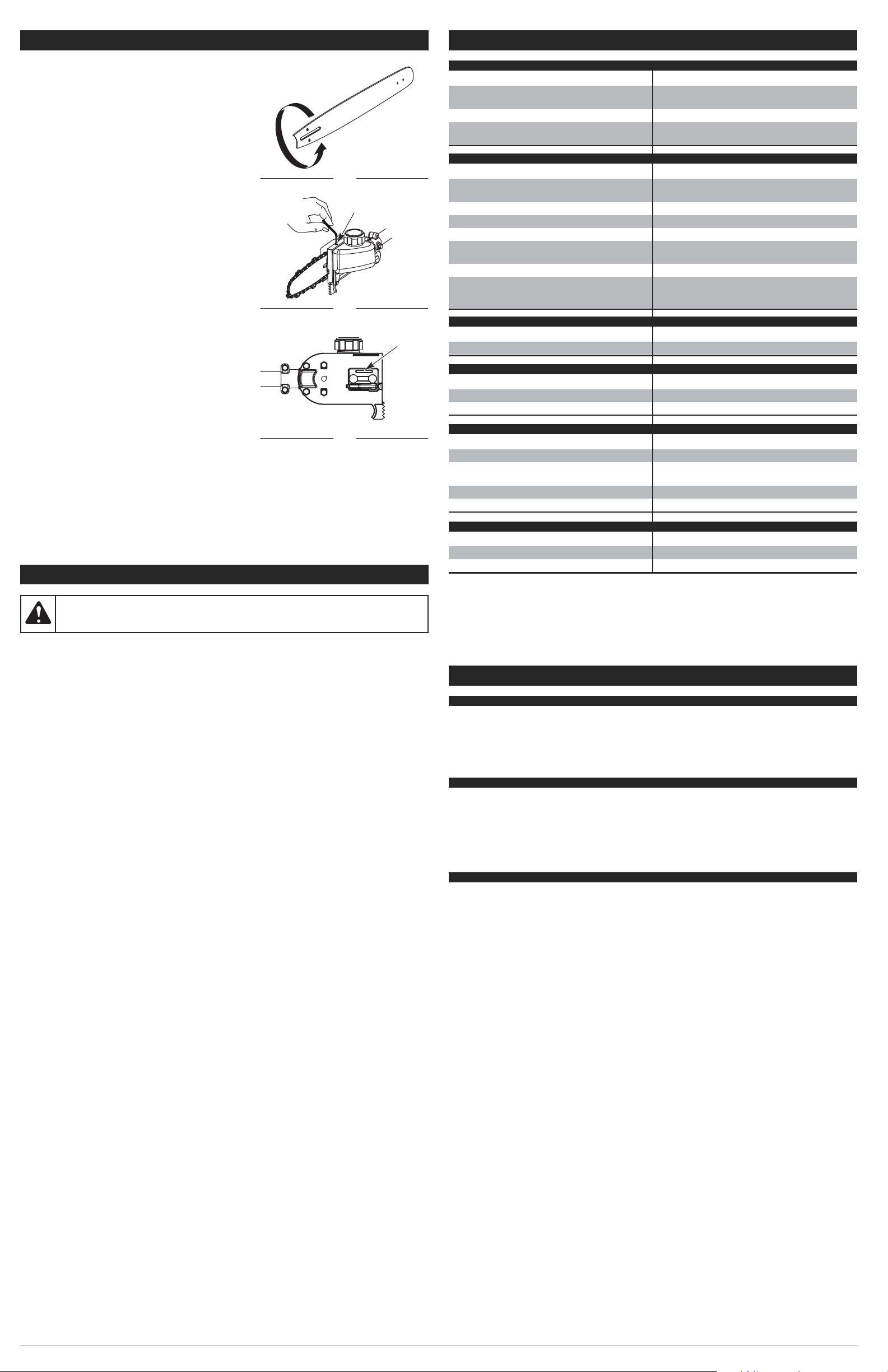
MAINTAINING THE GUIDE BAR
Clean the bar grooves after heavy use, when the saw chain
appears dirty and whenever the saw chain is removed.
Refer to Cleaning and Storage instructions. This will help
keep the oil passages open to provide proper lubrication to
the bar and chain.
After every week of use, rotate the guide bar on the saw to
distribute the wear for maximum guide bar life (Fig. 46).
Frequently check the guide bar for damage. Feathering and
burring of the guide bar rails (the ridges on either side of
the bar groove) is a normal process of guide bar wear. Such
faults should be smoothed with a file as soon as they occur.
A guide bar with the following faults should be replaced:
• Wear inside the guide bar rails that permits the chain to
lay sideways.
• Bent guide bar.
• Cracked or broken rails.
• Spread rails.
MAINTAINING THE BAR AND CHAIN LUBRICATION
Setting the Bar Lube Adjustment Screw
Oil is dispersed automatically onto the saw chain as the
unit is used. To adjust the rate of flow:
1. Insert a 3/32-inch Allen wrench into the bar lube
adjustment screw (Fig. 47).
2. Rotate the screw counterclockwise to increase the flow
of oil to the chain.
3. Rotate the screw clockwise to decrease the flow of oil to
the chain.
NOTE: Always keep an adequate amount of bar and
chain oil in the bar lube reservoir. Check the oil
level frequently and refill the reservoir as needed.
Oil Passages
The oil passages in the bar mount (Fig. 48) should be
cleared to ensure proper lubrication of the bar and chain
during operation. This can be done using a soft wire small
enough to insert into the oil discharge hole.
Fig. 46
Fig. 47
Bar Lube
Adjustment Screw
Fig. 48
Oil Discharge
Hole
CAUSE SOLUTION
The cord is not securely connected to the unit or
power source
Make sure each plug is securely connected
The GFCI in the outlet has tripped (if used) Reset the GFCI
The breaker switch has tripped
Reset the breaker switch in the home electrical
panel
CLEANING INSTRUCTIONS
1. Stop the motor and wait for all moving parts to stop.
2. Disconnect the unit from the power source and allow the unit to cool. Refer to Connecting and
Disconnecting the Power Source.
3. Slacken the pole saw chain if it was retensioned at operating temperature during cutting work. The
chain contracts as it cools down. If it is not slackened, it may damage the gearbox and bearings.
4. Wipe the unit down with a damp cloth. Do not douse the unit with water. Do not use solvents or
strong detergents. If preparing the unit for long-term storage (three months or more), remove the
chain and guide bar, then clean the unit thoroughly with a damp cloth. A firm-bristled, non-wire,
brush can be used to remove debris from the bar groove and assembly. When finished, reassemble
the unit. Refer to Removing/Replacing the Guide Bar and Chain.
5. Spray the guide bar and chain with corrosion inhibiting oil.
STORAGE INSTRUCTIONS
NOTE: It is normal for oil to seep from the pole saw Add-On when it is not in use. Please take this
into consideration when storing the unit.
1. Follow the Cleaning Instructions listed above.
2. Attach the scabbard to the guide bar and chain on the pole saw Add-On.
3. Store the unit indoors in a dry, high and/or locked location, out of the reach of children and other
unauthorized persons.
WARNING:
Do not let brake fluids, gasoline, petroleum-based products, penetrating oils,
etc., come in contact with plastic parts. These chemicals may damage, weaken and
destroy plastic, which may result in serious personal injury.
SPECIFICATIONS
MOTOR*
* All specifications are based on the latest product information available at the time of printing. We
reserve the right to make changes at any time without notice.
Motor Type . . . . . . . . . . . . . . . . . . . . . . . . . . . . . . . . . . . . . . . . . . . . . . . . . . . . . . . . . . . Electric, Corded
Motor Voltage . . . . . . . . . . . . . . . . . . . . . . . . . . . . . . . . . . . . . . . . . . . . . . . . . . . . . . . . . . . . . . . 120 VAC
Motor Amperage . . . . . . . . . . . . . . . . . . . . . . . . . . . . . . . . . . . . . . . . . . . . . . . . . . . . . . . . . . . . . 7 Amps
Operating RPM . . . . . . . . . . . . . . . . . . . . . . . . . . . . . . . . . . . . . . . . . . . . . . . . . . . . . . . up to 7,400 RPM
On/Off Switch. . . . . . . . . . . . . . . . . . . . . . . . . . . . . . . . . . . . . . . . . . . . . . . . . . . . . . . . . . . . . . . . . Trigger
CLEANING AND STORAGE
TROUBLESHOOTING
NOTE: For maintenance beyond the minor adjustments listed above, or for replacement parts, please
call the Customer Support Department at 1-800-828-5500 (U.S.) or 1-800-668-1238 (Canada).
THE MOTOR WILL NOT RUN
THE CUTTING ATTACHMENT WILL NOT ADVANCE LINE
REPLACEMENT PARTS
Description
Guide Bar
Saw Chain
Part #
753-05594
. . . . . . .
753-05592 . . . . . . .
THE CUTTING LINE ADVANCES UNCONTROLLABLY
THE BAR AND CHAIN ARE RUNNING HOT AND SMOKING OR STUCK
THE CHAIN DOES NOT ROTATE WHILE THE MOTOR IS RUNNING
THE CHAIN ROTATES, BUT DOES NOT CUT
DRIVE SHAFT AND CUTTING HEAD*
Drive Shaft . . . . . . . . . . . . . . . . . . . . . . . . . . . . . . . . . . . . . . . . . . . . . . . . . . . . . . . Steel T
ube (EZ-LinkTM)
Cutting Mechanism . . . . . . . . . . . . . . . . . . . . . . . . . . . . . . . . . . . . . . . . . . . . . . . . . . . . . . Bump Head
TM
Line Spool Diameter . . . . . . . . . . . . . . . . . . . . . . . . . . . . . . . . . . . . . . . . . . . . . . . . . 3 inches (76.2 mm)
Trimming Line Diameter. . . . . . . . . . . . . . . . . . . . . . . . . . . . . . . . . . . . . . . . . . . . 0.080 inches (2.03 mm)
Cutting Path Diameter . . . . . . . . . . . . . . . . . . . . . . . . . . . . . . . . . . . . . . . . . . . . . . 17 inches (43.18 mm)
Approximate Unit Weight (with cutting attachment, shield and D-handle) . . . . . . . . . . . . . . 9 lb (4.1 kg)
POLE SAW ADD-ON*
Drive Shaft Length . . . . . . . . . . . . . . . . . . . . . . . . . . . . . . . . . . . . . . . . . . . . . . . . . . . . 26 inches (66 cm)
Cutting Width
. . . . . . . . . . . . . . . . . . . . . . . . . . . . . . . . . . . . . . . . . . . . . . . . . . . . . . . . 8 inches (20.3 cm)
Approximate Weight of the Add-On. . . . . . . . . . . . . . . . . . . . . . . . . . . . . . . . . . . . . . . . 3 lb 5 oz (1.5 kg)
THE EZ-LINK
TM
SYSTEM
The EZ-Link
TM
system enables the use of these optional Add-Ons, which have not been evaluated for
Listing by Underwriters Laboratories Inc.:
Cultivator . . . . . . . . . . . . . . . . . . . . . . . . . . . . . . . . . . . . . . . . . . . . . . . . . . . . . . . . . . . . . . . . . . . . GC720
Edger. . . . . . . . . . . . . . . . . . . . . . . . . . . . . . . . . . . . . . . . . . . . . . . . . . . . . . . . . . . . . . . . . . . . . . . . LE720
Straight Shaft Trimmer . . . . . . . . . . . . . . . . . . . . . . . . . . . . . . . . . . . . . . . . . . . . . . . . . . . . . . . . . . SS725
Turbo Blower . . . . . . . . . . . . . . . . . . . . . . . . . . . . . . . . . . . . . . . . . . . . . . . . . . . . . . . . . . . . . . . . . TB720
Pole Saw . . . . . . . . . . . . . . . . . . . . . . . . . . . . . . . . . . . . . . . . . . . . . . . . . . . . . . . . . . . . . . . . . . . . PS720
Page 8

8
NOTES
Page 9

• CONSIGNES DE SÉCURITÉ IMPORTANTES •
PART NO. 769-05201 P00 (08/09)
Manuel de l’utilisateur
Scie à long manche / coupe-bordure électrique
TB138PS
TABLE DES MATIÈRES
Informations sur l’entretien et le service après-vente . . . . . . . . . . . . . . . . . . . . . . . . . . . . . . . . . . .F1
Informations sur la sécurité . . . . . . . . . . . . . . . . . . . . . . . . . . . . . . . . . . . . . . . . . . . . . . . . . . . . . .F1
Familiarisez-vous avec votre outil . . . . . . . . . . . . . . . . . . . . . . . . . . . . . . . . . . . . . . . . . . . . . . . . . .F3
Instructions de montage . . . . . . . . . . . . . . . . . . . . . . . . . . . . . . . . . . . . . . . . . . . . . . . . . . . . . . . . .F4
Instructions de démarrage et d’arrêt . . . . . . . . . . . . . . . . . . . . . . . . . . . . . . . . . . . . . . . . . . . . . . .F4
Instructions d’utilisation . . . . . . . . . . . . . . . . . . . . . . . . . . . . . . . . . . . . . . . . . . . . . . . . . . . . . . . . .F4
Entretien et réparations . . . . . . . . . . . . . . . . . . . . . . . . . . . . . . . . . . . . . . . . . . . . . . . . . . . . . . . . . .F5
Nettoyage et rangement . . . . . . . . . . . . . . . . . . . . . . . . . . . . . . . . . . . . . . . . . . . . . . . . . . . . . . . . .F7
Résolution des problèmes . . . . . . . . . . . . . . . . . . . . . . . . . . . . . . . . . . . . . . . . . . . . . . . . . . . . . . .F7
Spécifications . . . . . . . . . . . . . . . . . . . . . . . . . . . . . . . . . . . . . . . . . . . . . . . . . . . . . . . . . . . . . . . . .F7
Garantie . . . . . . . . . . . . . . . . . . . . . . . . . . . . . . . . . . . . . . . . . . . . . . . . . . . . . . . . . . . . . . . . . . . . .E8
NE RAMENEZ PAS CET APPAREIL CHEZ LE DÉTAILLANT. UNE PREUVE D’ACHAT SERA EXIGÉE
POUR TOUTE PRISE EN CHARGE DANS LE CADRE DE LA GARANTIE.
CE PRODUIT EST COUVERT PAR UN OU PLUSIEURS BREVETS AUX ÉTATS UNIS. AUTRES BREVETS
EN INSTANCE.
Si vous éprouvez des difficultés à assembler ce produit ou si vous avez des questions sur les
commandes, l'utilisation ou l'entretien de cet appareil, veuillez contacter le service à la clientèle. Des
informations supplémentaires sont disponibles sur notre site web.
Pour un entretien ou une réparation, veuillez appeler le service à la clientèle pour obtenir une liste complète
des concessionnaires agrées près de chez vous. L’entretien de cet appareil doit être confié exclusivement à
un concessionnaire agrée pendant et après la période de garantie. Lors de l’entretien, utilisez uniquement des
pièces de rechange identiques.
Avant de commencer, cherchez la plaque mentionnant le modèle et le numéro de série de votre appareil.
Reportez-vous à l’exemple ci-dessous et notez-y les informations pour pouvoir vous y référer ultérieurement.
Copiez ici le nº de série :
Copiez ici le modèle ainsi que le nº de l’article :
NE RAMENEZ PAS CET
APPAREIL AU MAGASIN
Pour obtenir de l’aide, veuillez appeler le service à la clientèle
ou visitez notre site web :
ou
DANGER :Signale un risque EXTREME.
Le non respect d’une consigne de sécurité relative à un signal de DANGER entraînera des
blessures graves ou mortelles pour vous-même ou pour les autres.
AVERTISSEMENT :Signale un risque GRAVE.
Le non respect d’un AVERTISSEMENT de sécurité PEUT entraîner des blessures graves
pour vous-même ou pour les autres.
ATTENTION :Signale un risque MOYEN.
Le non respect d’une consigne de signal d’ATTENTION PEUT entraîner des dégâts
matériels ou des blessures graves pour vous-même ou pour les autres.
IMPORTANT ! Signale une information technique spécifique.
REMARQUE : Signale une information générale importante supplémentaire.
SYMBOLE SIGNIFICATION
INFORMATIONS SUR LA SECURITÉ
• SYMBOLE D’ALERTE DE SECURITÉ •
L’objectif de ces symboles d’alerte de sécurité est d’attirer votre attention sur les dangers possibles.
Vous devez être attentifs aux symboles de sécurité, et à leurs explications. Les avertissements de
sécurité en eux-mêmes n’éliminent pas le danger. Les consignes ou avertissements de sécurité ne
se substituent pas aux mesures appropriées de prévention des accidents. Ces consignes de sécurité
ne sauraient couvrir toutes les éventualités susceptibles de se produire. Si vous avez des questions,
veuillez appeler le service à la clientèle au 1-800-828-5500 (E.U.) ou 1-800-668-1238 (Canada).
CONSERVEZ CES INSTRUCTIONS
L’ensemble des informations, illustrations et caractéristiques sont basées sur les toutes dernières
informations disponibles sur le produit à l’impression de ce guide. Nous nous réservons le droit
d’effectuer des modifications à tout moment sans notification préalable.
Copyright© 2009 MTD SOUTHWEST INC, Tous droits réservés.
Pour réduire l’impact sur les forêts et réduire les émissions de gaz carbonique et de
gaz à effet de serre, MTD utilise moins de papier en réduisant la taille du texte de ce
manuel.
INFORMATIONS SUR L’ENTRETIEN ET LE SERVICE APRÈS-VENTE
• Restez attentif. N’utilisez pas cet appareil lorsque vous êtes fatigué, malade, ou sous l’influence de
l’alcool, de drogues, ou de médicaments.
• Ne laissez jamais les enfants utiliser cet appareil. Ne laissez jamais des adultes utiliser cet appareil
sans qu’ils aient reçu une formation appropriée.
• Assurez-vous que toutes les protections et tous les dispositifs de sécurité ont été correctement
installés avant d’utiliser l’appareil.
• Conservez ces instructions. Consultez-les régulièrement et utilisez-les pour donner des consignes
aux autres utilisateurs. Si vous prêtez cet appareil à quelqu’un, prêtez-lui également ces instructions.
• Faites reculer les personnes se trouvant à proximité, en particulier les enfants et les animaux, d’au
moins 15 meters (50 pieds). Si quelqu’un s’approche de la zone de travail, arrêtez l’appareil !
• Veillez à ce que la zone de travail soit dégagée. Les zones encombrées favorisent les accidents. Ne
commencez pas à couper avant d’avoir éliminé tous les obstacles de la zone d’utilisation, d’avoir
une position parfaitement stable, et de vous être assuré qu’il y a suffisamment d’espace pour
reculer en cas de chute de branches.
• Portez toujours des protections oculaires et auditives lorsque vous utilisez cet appareil. Portez des
lunettes de sécurité ou un masque doté de protections latérales conformes aux normes ANSI
Z87.1-1989. Le non-port de ces protections peut entraîner de graves lésions oculaires suite à la
projection d’objets ou de débris. Si la tâche est poussiéreuse, portez un masque anti-poussière.
Lorsque vous utilisez l'appareil au-dessus de votre tête en tant que scie à long manche, portez un
casque de chantier ou un autre type de casque de sécurité.
• Habillez-vous de manière adéquate. Portez des gants et des bottes de travail antidérapants. Ne
portez pas de vêtements amples, de bijoux, de pantalons courts, de sandales et ne soyez pas
pieds nus. Attachez-vous les cheveux au dessus du niveau des épaules pour éviter qu’ils ne se
prennent dans les parties en mouvement de l’appareil.
• Utilisez l’appareil uniquement à la lumière du jour ou sous un éclairage artificiel satisfaisant.
• N’utilisez pas cet appareil pour des fonctions pour lesquelles il n’a pas été prévu. Utilisez l’appareil
uniquement tel qu’indiqué dans ce manuel.
• Utilisez uniquement les accessoires recommandés par le fabricant avec cet appareil. L’utilisation
avec cet appareil des accessoires scie à long manche / coupe-bordure à arbre courbé a été
approuvée par Underwriters Laboratories Inc. ; l’utilisation de tout autre accessoire est susceptible
d’augmenter le risque de blessure.
MESURES DE SÉCURITÉ POUR LE COUPE-BORDURE
• Inspectez attentivement la zone d’utilisation avant de démarrer l’outil. Retirez tous les débris et objets
durs et/ou tranchants tels que du métal, du verre, des câbles, etc. Si de tels objets sont projetés, ils
peuvent causer des dégâts matériels ou blesser l’utilisateur ou les personnes se trouvant à proximité.
• Utilisez uniquement un fil de coupe de rechange de 2,03 mm (0,080 pouces) de diamètre fourni par
le fabricant de l’équipement d’origine. N’utilisez jamais de fil, de câble ou de cordon à renfort
métallique. Ces derniers peuvent céder et devenir des projectiles dangereux.
• Cet appareil n’a pas été conçu pour être utilisé en tant que débroussailleuse. N’utilisez cet appareil
avec aucun type de lame ou d’accessoire de débroussaillage.
• Nettoyez bien l’appareil de tous végétaux ou autres matériaux. Ceux-ci peuvent se coincer entre
l’accessoire de coupe et l’écran.
• L’écran de l’accessoire de coupe doit toujours être en place lorsque vous vous servez de cet
appareil comme coupe-bordure. N'utilisez pas l’appareil sans une longueur suffisante des deux fils
de coupe, ces derniers devant être ceux recommandés par le fabricant. La longueur du fil de coupe
ne doit jamais aller au-delà de celle de l’écran.
• Une vigilance accrue est requise lors de l’utilisation de l’appareil à des fins de taille de bordure. Il
existe un risque accru de blessure ou de dommage matériel causé par des objets projetés lorsque
l’écran de l’accessoire de coupe n’est pas maintenu horizontal par rapport au sol.
LIRE TOUTES LES INSTRUCTIONS AVANT UTILISATION
PRECAUTIONS DE SECURITE ELEMENTAIRES
• NE vous fiez PAS exclusivement aux protections de sécurité incorporées dans l’appareil.
• NE PAS laisser l'unité à être utilisé comme un jouet.
• Veuillez lire ce manuel de l’utilisateur attentivement et dans sa totalité avant d’essayer de monter,
d’utiliser ou d’entretenir l’appareil.
• Conformez-vous à toutes les consignes de sécurité. Le non respect de ces consignes peut
entraîner des dégâts matériels ou des blessures graves pour vous-même et/ou pour les autres.
• Familiarisez-vous avec les commandes et la marche à suivre pour une utilisation correcte de cet appareil.
Apprenez à rapidement couper le moteur de l’appareil et à mettre les commandes en position neutre.
AVERTISSEMENT :Lors de l’utilisation d'outils électriques,
respectez toujours les précautions de sécurité élémentaires afin de réduire les risques
d’incendie, de décharges électriques et de blessures graves :
aux États Unis
1-800-828-5500
www.troybilt.com
au Canada
1-800-668-1238
www.troybilt.ca
S/N :
MODEL :
ITEM :
Page 10

F2
INFORMATIONS SUR LA SECURITÉ
COMPRENDRE L’EFFET DE REBOND
•Un rebond rotatif peut se produire lorsque la partie
supérieure de la pointe du guide heurte un objet alors
que la chaîne est en mouvement (Fig. 1 & 2). La chaîne
peut en conséquence s’enfoncer dans l'objet et s’arrêter
momentanément de tourner. Le guide est alors propulsé
vers le haut à toute vitesse et se retourne vers
l'utilisateur dans un mouvement inverse ultra-rapide.
•Un effet de rebond par coincement peut se produire
lorsque le bois se referme de chaque côté d'une coupe et
coince la chaîne en mouvement au niveau du haut du
guide. Ceci peut caler la chaîne net. La force de la chaîne
est ainsi renversée, ce qui provoque un retour instantané
et soudain de la tronçonneuse vers l’utilisateur.
•Un effet de calage peut se produire lorsque la chaîne en
mouvement sur la partie inférieure du guide heurte un objet
étranger dans le bois. Ceci peut caler la chaîne net. La
tronçonneuse est alors propulsée en avant et s’écarte de
l’utilisateur, qui pourrait potentiellement en perdre le contrôle.
PRÉCAUTIONS DE SECURITÉ POUR ÉVITER L’EFFET
DE REBOND
• N’effectuez PAS de coupes avec la pointe du guide (Fig. 1).
• Veillez à ce que la pointe du guide n’heurte aucun objet tel
qu’une bûche, une branche, le sol ou tout autre élément
gênant. Retirez ou évitez les éléments gênants susceptibles
de butter contre l'extrémité du guide lors de la coupe.
• NE coupez PAS plus d’une branche à la fois.
• NE tordez PAS la tronçonneuse lorsque vous retirez le guide d’une entaille.
• Tenez-vous un peu sur la gauche de l’appareil pour éviter d’être dans la ligne directe de la chaîne
coupante. Suivez toutes les instructions de Prise correcte sur les poignées dans la section
Instructions d’utilisation.
• Ne démarrez jamais la tronçonneuse lorsque le guide se trouve dans une entaille. Soyez
extrêmement prudent lorsque vous recoupez dans une entaille.
• Commencez toujours une coupe avec le moteur à plein régime. Enfoncez complètement l’interrupteur
à gâchette et maintenez une vitesse de coupe constante. Les vitesses réduites sont plus propices
aux effets de rebond. Maintenez le corps de la tronçonneuse fermement appuyé contre le bois.
• Veillez à ce qu’aucune bûche, branche instables, ou autre objet ne se coince ou heurte la chaîne
lors de la coupe.
• Si vous utilisez des coins d’abattage, utilisez uniquement des modèles en plastique ou en bois.
N’utilisez jamais d’objet métallique pour maintenir une coupe ouverte.
• Suivez les instructions du fabriquant concernant l’affûtage et l’entretien de la chaîne coupante.
• N’utilisez que des guides et chaînes de remplacement recommandés par le fabricant ou de qualité
équivalente. Ils sont disponibles auprès d’un distributeur officiel. L’utilisation de pièces ou
accessoires non agréés pourrait entraîner de graves blessures pour l'utilisateur, ou endommager
l'appareil et annuler votre garantie.
• Utilisez des dispositifs tels que des chaînes à faible rebond, des protections pour nez de guide, des
freins de chaîne et des guides spécifiques, qui permettent de réduire les risques associés aux
effets de rebond. Il n'existe pas d'autres composants de remplacement conformes à la norme CSA
Z62.3 permettant de se prémunir des rebonds.
• Une chaîne coupante à faible rebond est une chaîne qui répond aux exigences de performance de
la norme ANSI B175.1-1991 et qui est conforme à la norme CSA Z62.3. N’utilisez une chaîne de
remplacement que si celle-ci est conforme aux exigences s’appliquant au modèle concerné.
Certaines des qualités de faible rebond pouvant disparaître avec l’affûtage des chaînes, il est
recommandé de redoubler de prudence.
MESURES DE SÉCURITÉ POUR LA SCIE À LONG MANCHE
• NE coupez PAS à proximité de câbles électriques.
• N’utilisez PAS la scie à long manche pour abattre un arbre. Pour ceci, utilisez une tronçonneuse ordinaire.
• Lorsque vous coupez une branche maîtresse sous tension, faites attention au risque de rebond. La
branche peut en effet frapper l’utilisateur lorsque la tension des fibres du bois se relâche.
• Faites attention lorsque vous coupez des petits taillis ou de jeunes arbres car les branches fines
peuvent se prendre dans la chaîne coupante et se projeter vers l’utilisateur ou le déséquilibrer.
• Cette tronçonneuse appartient à la classe 2C définie par l’UL. Elle est destinée à un usage domestique
et peu fréquent pour l’entretien du jardin d’une maison, d’un chalet ou d’un mobile-home et pour des
tâches générales telles que le défrichage, l’élagage, la coupe de bois à brûler, etc. Elle n’est pas
conçue pour être utilisée pendant des périodes prolongées. En cas d'utilisation prolongée, des
problèmes circulatoires peuvent survenir au niveau des mains de l'utilisateur en raison des vibrations.
Dans ce cas, il peut s’avérer opportun d'utiliser une tronçonneuse munie d'une fonction anti-vibration.
PRECAUTIONS DE SECURITE D’ORDRE GENERAL
• NE manipulez PAS l’appareil, la prise ou le cordon avec des mains mouillées.
• N’essayez PAS d’atteindre des espaces trop éloignés.
• N’utilisez PAS cet appareil sur des surfaces instables telles que des arbres, des échelles, des talus
ou des toits. Faites très attention si vous utilisez cet appareil sur un escalier.
• NE laissez PAS l’appareil sous la pluie. N’utilisez pas l'appareil dans des conditions ou des
endroits humides ou mouillés.
• N’utilisez PAS l'appareil sur des surfaces mouillées.
• N’utilisez PAS l'appareil en présence de liquides inflammables ou de gaz.
• N’utilisez PAS cet appareil lorsqu’il est endommagé, mal réglé, ou mal assemblé. Assurez-vous
que l’appareil se coupe lorsque l’interrupteur est en position ARRÊT. N’utilisez PAS l’appareil si
l’interrupteur ne parvient pas à démarrer ni à arrêter correctement l’appareil. Faites remplacer les
interrupteurs défectueux par un professionnel agréé.
• N’effectuez PAS de tâches qui vont au delà des capacités ou de l’expérience de l’utilisateur.
• N’utilisez PAS l’appareil d’une seule main. Cela pourrait entraîner des blessures sérieuses pour
l’utilisateur, ses assistants, ou les personnes se trouvant à proximité. Cet appareil est conçu pour
être utilisé avec les deux mains. Tenez l’appareil fermement des deux mains lorsque le moteur
tourne. Gardez la main gauche sur la poignée en D et la main droite sur la prise de l’arbre. Gardez
une prise ferme avec les doigts et les pouces bien placés autour des poignées. Ne lâchez pas !
• NE forcez PA
S l’appareil. L’outil sera plus efficace et plus sûr si vous l’utilisez à la vitesse pour
laquelle il a été conçu.
• NE laissez PAS l’appareil sans surveillance lorsqu’il est branché sur la prise électrique.
Débranchez l’appareil de la prise électrique lorsque vous ne l’utilisez pas.
• Réglez la poignée en D de manière à avoir la meilleure prise possible.
• Garder les cheveux, les vêtements amples, les doigts et toutes les parties du corps à l'écart des
parties en mouvement. N’essayez pas de touchez ou d’arrêter les parties en mouvement
(accessoire de coupe ou chaîne de la scie à long manche) lorsque celles-ci sont en rotation.
• Assurez-vous de toujours garder une position stable et un bon équilibre.
• Assurez-vous que l’accessoire de coupe/la chaîne de la scie à long manche ne sont pas en contact
avec quoi que ce soit avant de démarrer l’appareil.
• Arrêtez toujours le moteur lorsque le fonctionnement est interrompu, avant de déposer l’appareil ou
lorsque vous vous déplacez vers une autre aire de coupe. Assurez-vous que l’appareil s’arrête
complètement.
• Pour éviter les démarrages accidentels, ne portez jamais l’appareil avec vos doigts sur l’interrupteur.
• Vérifiez toujours que la gâchette est relâchée avant de brancher l’appareil à la prise électrique ou
de le débrancher de celle-ci.
• Portez toujours l’appareil à deux mains et assurez-vous qu’il est débranché de la prise électrique et
que vos doigts n’appuient pas sur l’interrupteur. Lorsque vous utilisez l’appareil en tant que scie à
long manche, portez-le toujours avec la barre de guidage et la chaîne rangées dans le fourreau et
positionnées à l’arrière.
• Si l’appareil heurte un objet étranger ou s’emmêle avec celui-ci, arrêtez le moteur immédiatement,
débranchez l’appareil de la prise électrique et vérifiez que l’appareil n’a pas été endommagé. Ne
redémarrez ni n'utilisez l’appareil avant d’avoir réparé les dégâts.
INFORMATIONS SUR LA SECURITÉ
PRECAUTIONS DE SECURITE CONCERNANT L’ELECTRICITE
• Ménagez la rallonge. Vous ne devez jamais tirer ou porter l’appareil par le cordon, utiliser le cordon
en guide de poignée, refermer une porte sur le cordon, tirer le cordon autour de rebords ou de
coins coupants, ni tirer le cordon d’un coup sec pour débrancher l’appareil. Saisissez la prise, et
non le cordon, pour débrancher l’appareil.
• NE modifiez en aucune façon le cordon électrique, la rallonge, la prise du cordon électrique ou de
la rallonge ou la prise murale.
• N’utilisez PAS plusieurs rallonges.
• Gardez les cordon à l’écart de matières telles que l’essence ou l’eau, et d’objets pointus et de
sources de chaleur.
• Maintenez le cordon à l’écart de la zone de coupe et placez-le de manière à ce qu’il ne se prenne
pas dans les branches ou d’autres obstacles susceptibles de coincer ou d’emmêler le cordon lors
de l’utilisation.
• Maintenez les cordon à l’écart des pieds de l’utilisateur pour éviter de le faire trébucher.
• Assurez-vous que le cordon est en bon état. Inspectez régulièrement le cordon électrique et la rallonge.
Faites attention aux éventuelles détériorations, coupures ou déchirures au niveau de l’isolation. Si le
cordon électrique est endommagé, faites-le réparer par un professionnel agrée. Si la rallonge est
endommagée, remplacez-la. N’utilisez jamais l’appareil avec une prise ou un cordon endommagé(e).
• Si la rallonge est endommagée lorsqu’elle est branchée, retirez-la de la prise.
• Cet appareil étant équipé d’une double isolation, une rallonge à deux conducteurs (une rallonge sans
mise à la terre) peut être utilisée. L’utilisation d’une rallonge à trois conducteurs (une rallonge avec
mise à la terre) disposant d’un connecteur de type NEMA (broche parallèle, mise à la terre U) est
toutefois recommandée. Vous pouvez vous procurer des rallonges auprès des revendeurs locaux.
Utilisez uniquement les rallonges à gaine ronde homologuées pour une utilisation à l’extérieur.
• Assurez-vous que votre rallonge est suffisamment résistante pour supporter le courant requis par
l’appareil. Un câble de calibre trop petit entraînera une baisse de tension, une perte de puissance,
ainsi qu’une surchauffe. En cas de doute, utilisez une rallonge de calibre plus élevé. Plus la valeur
de la jauge est petite, plus le câble est résistant.
• Pour réduire les risques de décharges électriques, cet appareil dispose d’une prise polarisée (une
broche est plus large que l’autre) et nécessite l’utilisation d’une rallonge polarisée. La prise du
cordon électrique de l’appareil ne peut s’insérer dans une rallonge polarisée que dans un sens. Si la
prise ne correspond pas exactement à la rallonge, inversez le branchement. Si la fiche ne
correspond toujours pas, procurez-vous une autre rallonge polarisée. Une rallonge polarisée
nécessitera l’utilisation d’une prise murale polarisée. Cette prise ne peut s’insérer dans une prise
murale polarisée que dans un sens. Si la prise ne correspond pas exactement à la prise murale,
inversez le branchement. Si la fiche ne correspond pas exactement à la prise murale, appelez un
électricien qualifié pour installer une prise adéquate dans le mur.
• La tension utilisée est indiquée sur une plaque signalétique située sur votre appareil. Ne jamais
brancher l’appareil à une tension CA différente de cette tension.
• Une protection GFCI (Ground Fault Circuit Interrupter- défaillance de terre, coupe-circuit) devrait
être fournie sur le(s) circuit(s) ou la(les) prise(s) utilisé(e)s pour l’appareil. Pour plus de sécurité,
utilisez des prises disposant d’une protection GFCI intégrée.
• Pour réduire le risque de débranchement de la rallonge de l’appareil, utilisez le dispositif de retenue
de rallonge fourni.
• Pour réduire le risque d’électrocution, évitez tout contact avec des conducteurs de mise à la terre,
tels que des tuyaux métalliques ou des grillages.
ENTRETIEN ET REPARATION D’UN APPAREIL A DOUBLE ISOLATION
• Cet appareil est équipé d’une double isolation. Deux systèmes d’isolation sont fournis à défaut
d’une mise à la terre. Aucune mise à la terre n’est fournie et aucun dispositif de mise à la terre ne
devrait être ajouté sur l’appareil. Les réparations sur un appareil à double isolation exigent une
attention extrême et une connaissance approfondie du système et devraient être effectuées
exclusivement par des professionnels qualifiés. Les pièces de rechange utilisées sur un appareil à
double isolation doivent être identiques à celles d’origine. À défaut de confier la réparation d’un
appareil à double isolation à un technicien agrée utilisant des pièces de rechange identiques,
l’appareil peut provoquer des blessures graves.
PRÉCAUTIONS CONCERNANT L’ENTRETIEN ET LE RANGEMENT
• Si l’appareil ne fonctionne pas normalement, s’il est tombé, a été endommagé, a été laissé dehors ou
est tombé dans l’eau, ne l’utilisez pas. Confiez l’entretien et la réparation à un professionnel agrée.
• Toutes réparations autres que les procédures d’entretien décrites dans ce manuel devraient être
effectuées par un professionnel agrée. N’essayez pas de réparer vous-même l’appareil ; il ne
contient aucune pièce remplaçable par l’utilisateur.
• Suivez toutes les instructions d’entretien décrites dans ce manuel.
• Avant la vérification, l’entretien, le nettoyage, le rangement, le transport, le remplacement de pièces
ou le changement d’accessoires de l'appareil :
1. Arrêtez le moteur. Vérifiez que la gâchette est relâchée.
2. Assurez-vous que toutes les pièces mobiles se sont arrêtées.
3. Débranchez l’appareil de la prise électrique.
4. Laissez refroidir l’appareil.
• N’enlevez, ne modifiez ou ne désactivez jamais un dispositif de sécurité qui est fourni avec l’appareil.
• Pour renforcer la sécurité et obtenir des performances optimales, assurez-vous que le guide et la
chaîne sont parfaitement propres, graissés, resserrés et affûtés. Vérifiez régulièrement que le guide
et la chaîne sont correctement ajustés.
• Vérifiez régulièrement l’appareil pour vous assurer qu’il n’est pas endommagé. Avant d’utiliser
l’appareil, toute pièce endommagée devrait être inspectée pour déterminer si elle fonctionnera
correctement et remplira sa fonction comme il se doit. Vérifiez l’alignement et la fixation de toutes
les pièces mobiles, assurez-vous qu’aucune pièce n’est brisée et qu’aucun autre problème n’est
susceptible d'affecter le fonctionnement de l’appareil. Toute pièce endommagée devrait être
réparée ou remplacée par un professionnel agrée, sauf indication contraire dans ce manuel.
• Si l’appareil commence à vibrer de façon anormale, arrêtez le moteur, débranchez l’appareil de la
prise électrique et laissez l’appareil refroidir. Inspectez ensuite l’appareil à la recherche de l’origine
de la vibration. Une vibration indique généralement un problème.
• N’utilisez que des pièces de rechange et accessoires de la marque du fabriquant qui sont
spécifiquement conçus pour améliorer les performances et maximiser la sûreté de fonctionnement de
l’appareil. À défaut, l’appareil risque de produire des performances médiocres et même des blessures.
Utilisez exclusivement la chaîne et le guide fournis avec le produit.
• Assurez-vous que l’appareil est sécurisé pour les transports.
• Utilisez toujours le fourreau sur le guide et la chaîne pendant le transport et lors du rangement.
• Quand l’appareil n’est pas utilisé, rangez-le à l’intérieur, dans un endroit sec et sous clé ou sec et
en hauteur pour éviter un usage non autorisé ou des dommages. Gardez toujours l’appareil hors de
la portée des enfants.
• Veillez à ce que les poignées restent sèches, propres et dépourvues d’huile et de graisse. Nettoyez
l’appareil après chaque utilisation. Ne jamais tremper ou vaporiser l’appareil avec de l’eau ou tout
autre liquide. Ne nettoyez pas l’appareil avec un tuyau d’arrosage, évitez la pénétration d’eau dans
le moteur et les branchements électriques. N’utilisez pas de solvants ou de détergents agressifs.
DANGER :
Un effet de rebond peut se produire lorsque le nez ou la pointe du
guide touche un objet, ou lorsque le bois se referme et coince la chaîne lors de la coupe.
Dans certains cas, un contact avec l'extrémité de l’outil peut causer un effet de rebond
extrêmement rapide, retournant ainsi le guide instantanément vers l'utilisateur. Coincer la
chaîne coupante sur le haut du guide risque de retourner rapidement le guide vers
l'utilisateur. L’une et l’autre de ces réactions peuvent provoquer une perte de contrôle de la
tronçonneuse, ce qui peut entraîner des blessures graves pour l'utilisateur. Si la
tronçonneuse heurte ou se prend dans un objet étranger dans le bois, cela peut également
provoquer une perte de contrôle de la chaîne coupante.
Fig. 2
Zone de danger présentant
un risque de rebond
Fig. 1
Rebond
rotatif
TAILLE MINIMUM DE FIL POUR LES RALLONGES
DES APPAREILS DE 120 VOLTS ET 0-12 AMPÈRES
LONGUEUR DU FIL (PIEDS) 25 50 100 150
CALIBRE DU CÂBLE (AWG) 16 16 14 12
AVERTISSEMENT :Pour réduire les risques de décharges
électriques, utilisez uniquement une rallonge pour usage extérieur, telle que les rallonges de
type SW-A, SOW-A, STW-A, STOW-A, SJW-A, SJOW-A, SJTW-A, ou SJTOW-A.
Page 11

F3
• SYMBOLES INTERNATIONAUX ET DE SECURITÉ •
Ce manuel de l’utilisateur décrit les symboles et pictogrammes de sécurité et internationaux qui
peuvent apparaître sur ce produit. Lisez ce manuel de l’utilisateur pour une information complète sur
la sécurité, l’assemblage, l’utilisation l’entretien et les réparations.
• SYMBOLE D’ALERTE DE SECURITÉ
Indique le danger, l’avertissement ou la prudence. Peut être utilisé conjointement avec
d’autres symboles ou pictogrammes.
• LISEZ LE MANUEL DE L’UTILISATEUR
AVERTISSEMENT :Lisez le(s) manuel(s) de l’utilisateur et
suivez toutes les consignes de sécurité et de prévention. Tout manquement peut
entraîner des blessures graves pour les utilisateurs et/ou pour les personnes à
proximité de l’appareil.
• N’UTILISEZ PAS CET APPAREIL SOUS LA PLUIE
AVERTISSEMENT :Évitez les environnements dangereux.
N’utilisez jamais cet appareil sous la pluie ou dans des conditions atmosphériques
humides. L’humidité est un risque d’électrocution.
CONSERVEZ CES INSTRUCTIONS
• DOUBLE ISOLATION
Deux systèmes d’isolation sont fournis à défaut d’une mise à la terre. Aucune mise à
la terre n’est fournie et aucun dispositif de mise à la terre ne devrait être ajouté sur
l’appareil.
FAMILIARISEZ-VOUS AVEC VOTRE OUTILINFORMATIONS SUR LA SECURITÉ
• PORTEZ UN CASQUE, DES LUNETTES DE SECURITÉ ET DES BOUCHONS ANTIBRUITS
AVERTISSEMENT :
Les objets projetés et le bruit peuvent
entraîner des lésions oculaires et des pertes auditives. Portez des protections oculaires
conformes aux normes ANSI Z87.1-1989 et des protections auditives lorsque vous
utilisez cet outil. Le port du casque est obligatoire lors de l’utilisation de cet appareil ; la
chute d'objets peut entraîner de graves blessures à la tête. Utilisez une protection pour
le visage si nécessaire.
SYMBOLE SIGNIFICATION
• LES OBJETS PROJETÉS ET LA TÊTE DE COUPE PEUVENT CAUSER DES
BLESSURES GRAVES
AVERTISSEMENT :
De petits objets peuvent être projetés à
grande vitesse, causant des blessures. Tenez-vous à l’écart du couteau rotatif.
• PORTEZ DES CHAUSSURES DE TRAVAIL
Portez des chaussures de travail antidérapantes lorsque vous utilisez cet appareil.
• PORTEZ DES GANTS DE TRAVAIL
Portez des gants de protection antidérapants lorsque vous manipulez l’appareil.
• LAME AIGUISÉE
AVERTISSEMENT :
L’écran de l’accessoire de coupe
comporte une lame aiguisée. Afin d’éviter les blessures graves, ne touchez pas la lame
de coupe sur l’écran de sécurité.
• ÉLOIGNEZ LES PERSONNES SE TROUVANT À PROXIMITÉ
AVERTISSEMENT :
Faites reculer les personnes se trouvant
à proximité, en particulier les enfants et les animaux, d’au moins 50 pieds (15 m) de la
zone de travail. Si quelqu’un s’approche de la zone de travail, arrêtez l’appareil !
• LES LIGNES ÉLECTRIQUES PEUVENT CAUSER DES BLESSURES GRAVES
DANGER :
N’utilisez pas cet appareil à proximité de lignes électriques.
Tout contact avec une ligne électrique peut provoquer des blessures graves ou
endommager l’appareil. Maintenez une distance d'au moins 50 pieds (15 m) entre la
tronçonneuse sur perche (y compris les branches avec lesquelles l’outil est en
contact) et toute ligne électrique.
AVERTISSEMENT :Assurez-vous que la zone de travail est
parfaitement dégagée et que vous disposez de suffisamment d’espace pour reculer.
Soyez attentif à l’emplacement des branches pour éviter de vous blesser avec des
débris ou lors de la chute de branches.
• AVERTISSEMENT RELATIF A L’EFFET DE REBOND
Il faut absolument éviter que le bout du guide entre en contact avec tout autre objet.
Si le bout du guide heurte un objet, le guide peut brusquement être propulsé vers le
haut ou vers l'arrière et causer des blessures graves.
• UTILISEZ VOS DEUX MAINS
Utilisez toujours vos deux mains pour travailler avec la tronçonneuse sur perche.
N’utilisez jamais l’appareil d’une seule main.
• COMMANDE DES GAZ
Indique « RALENTI », « VITESSE LENTE » ou « VITESSE MINIMALE »
• COMMANDE DES GAZ
Indique « VITESSE RAPIDE » ou « VITESSE MAXIMALE ».
Écran de
l’accessoire
de coupe
Logement
du moteur
APPLICATIONS
Cet appareil peut être utilisé pour les tâches suivantes :
En tant que coupe-bordure :
• Coupe d’herbe et de mauvaises herbes légères
• Taille décorative autour des arbres, des clôtures, etc.
En tant que scie à long manche :
• Coupe de branches maîtresses de petite taille
• Taille et élagage général des arbres
Comme spécifié dans le présent manuel, d’autres
accessoires optionnels, qui n’ont pas été évalués
par Underwriters Laboratories Inc., peuvent être
utilisés avec cet appareil. Consultez le système EZ-
Link
TM
pour une liste d’accessoires.
Poignée en D
Gâchette
Chaîne
coupante à
faible rebond
Extrémité
de la
barre de
guidage
Guide
Lame du
fil de
coupe
Fourreau
Conversion en
coupe-bordure
Transformation de la
tronçonneuse sur perche
Prise de
l’arbre
Interrupteur 2 vitesses
Dispositif de
retenue de
cordon (non
représenté)
Accessoire
de coupe
Fiche à
empreinte carrée
Couvre-barre
Écrous de
blocage de
la barre
Bouchon du réservoir d’huile
pour la lubrification de la chaîne
Vis de réglage de
lubrification de la barre
Arbre d’entraînement
Rallonge
télescopique
Coupleur
EZ-Link
TM
Crochet de suspension
Réservoir de
lubrifiant
Vis de réglage de
tension de la chaîne
Page 12

Retrait des accessoires ou de la rallonge télescopique
1. Tournez le bouton dans le sens inverse à celui des aiguilles d’une montre pour desserrer le
coupleur EZ-Link
TM
(Fig. 9).
2. Appuyez sur le bouton-ressort et maintenez-le enfoncé.
3. Tout en maintenant fermement le corps de l’arbre supérieur (Fig. 11), retirez l’accessoire ou la
rallonge télescopique du coupleur EZ-Link
TM
.
Test de la connexion du coupleur EZ-Link
TM
Après avoir monté un accessoire, testez toujours l’appareil :
1. Démarrez le moteur. Consultez les Instructions de
démarrage et d’arrêt.
2. Enfoncez la gâchette un court moment, puis relâchez-la.
3. Vérifiez que l’accessoire fonctionne. Si ce n’est pas le
cas, retirez puis réinstallez l’accessoire (et la rallonge
télescopique, si vous en utilisez une).
4. Répétez ces étapes jusqu’à ce que l’accessoire fonctionne.
BRANCHER ET DÉBRANCHER LA SOURCE
D’ALIMENTATION
Observez ces instructions pour éviter des blessures et
réduire le risque d’électrocution ou d’incendie :
• Vérifiez que la gâchette est relâchée et que le moteur est
éteint avant de brancher l’appareil à la prise électrique ou de le débrancher de celle-ci. Consultez
les Instructions de démarrage et d’arrêt.
• Assurez-vous que le moteur est éteint et que l’appareil est débranché de la prise électrique avant
de vérifier, d’ajuster ou de réaliser l’entretien d’une partie quelconque de l’appareil.
N’utilisez que des rallonges prévues pour être utilisées en extérieur. Les cordons amovibles sont
spécifiés dans la section Informations importantes sur la sécurité.
Brancher l'alimentation
1. Faites une boucle étroite avec la rallonge et faites-la passer à travers l’ouverture inférieure du
dispositif de retenue de cordon (Fig. 12).
2. Déplacez la boucle sur le crochet d'enroulement du cordon et tirez délicatement sur le cordon pour
la fixer dessus (Fig. 12). Cela permet d’éviter de débrancher accidentellement le cordon.
3. Branchez la rallonge dans la fiche à empreinte carrée de l’appareil (Fig. 12).
4. Branchez la prise de la rallonge sur la prise électrique.
Débrancher l'alimentation
1. Débranchez la prise de la rallonge de la prise électrique.
2. Retirez la boucle de la rallonge du crochet d'enroulement du cordon.
3. Débranchez la rallonge de la fiche à empreinte carrée de l’appareil (Fig. 12).
F4
AVERTISSEMENT :
Pour éviter des blessures graves, ne portez pas de vêtements
amples, tels que des foulards, cordons, chaînes ou cravates susceptibles d’être aspirés
dans l’entrée d’air. Les cheveux longs doivent être tirés vers l'arrière et attachés à hauteur
des épaules et du cou.
AVERTISSEMENT :
Restez vigilent et concentré même lorsque vous êtes parfaitement
familiarisé avec l’appareil. N’oubliez pas qu’une fraction de seconde d’inattention suffit pour
causer une blessure importante.
AVERTISSEMENT :
Portez toujours des protections oculaires et auditives adaptées
lorsque vous utilisez cet appareil. Portez des lunettes de sécurité ou un masque doté de
protections latérales conformes aux normes ANSI Z87.1-1989. Le non-port de ces
protections peut entraîner de graves lésions oculaires suite à la projection d’objets ou de
débris. Si la tâche est poussiéreuse, portez un masque anti-poussière. Lorsque vous utilisez
l'appareil au-dessus de votre tête en tant que scie à long manche, portez un casque de
chantier ou un autre type de casque de sécurité.
AVERTISSEMENT :
Si des pièces sont endommagées ou manquantes, n’utilisez pas
l’appareil avant de les avoir remplacées. Le non respect de cet avertissement peut entraîner
des blessures graves.
AVERTISSEMENT :
Portez des gants antidérapants pour garantir une prise parfaite et
votre sécurité. Consultez la section Informations sur la sécurité pour en savoir plus sur les
équipements de sécurité adéquats.
AVERTISSEMENT :
Ne laissez pas l’appareil sous la pluie. N’utilisez pas l'appareil
dans des conditions ou des endroits humides ou mouillés.
INSTRUCTIONS D’ASSEMBLAGEINSTRUCTIONS D’ASSEMBLAGE
Cet appareil doit être assemblé.
DÉBALLER
• Retirez soigneusement l’appareil et ses accessoires de la
boîte.
• Inspectez soigneusement l’appareil pour vous assurer qu’il
n’a pas été endommagé pendant le transport.
• Ne jetez pas l’emballage tant que vous n’avez pas
inspecté et testé l’appareil de façon satisfaisante.
• Si des pièces sont endommagées ou manquantes,
veuillez appeler le 1-800-828-5500 (E.U.) ou le 1-800-
668-1238 (Canada) pour obtenir de l’aide.
INSTALLATION ET AJUSTEMENT DE LA POIGNÉE EN D
1. Poussez la poignée en D vers le bas sur l’arbre (Fig. 3).
Le trou pour boulon de fixation de la poignée en D se
trouve sur la droite.
2. Insérez le boulon de fixation dans le trou de la poignée
en D et serrez-le partiellement. Ne serrez pas
complètement le boulon de fixation avant d’avoir
effectué le réglage de la poignée en D.
3. Tout en tenant l’appareil en position d’utilisation (Fig. 4),
positionnez la poignée en D de manière à assurer une
prise idéale. Placez-la à au moins 15,24 cm (6 pouces)
de l’extrémité de la prise de l’arbre.
4. Serrez le boulon de fixation jusqu’à ce que la poignée en
D soit bien fixée.
MONTAGE DU COUPE-BORDURE INSTALLATION DE
L’ÉCRAN DE L’ACCESSOIRE DE COUPE
Respectez les instructions suivantes si l’écran de
l’accessoire de coupe n’est pas installé sur l’appareil :
1. Placez l’écran de l’accessoire de coupe dans le corps
de l’arbre. Assurez-vous que le support de fixation du
dispositif de protection coulisse dans la rainure sur le
bord de l’écran de coupe. Faites tourner l’écran dans le
sens inverse de celui des aiguilles d’une montre pour le
mettre en place. Les trous du support de fixation du
dispositif de protection et de l’écran de l’accessoire de
coupe vont s’aligner (Fig. 5).
2. Depuis l’intérieur de l’écran de l’accessoire de coupe,
poussez le boulon à tête carrée jusqu’à ce que
l’extrémité filetée dépasse à travers le support de
fixation du dispositif de protection (Fig. 6).
3. Poussez la rondelle sur le boulon, puis vissez l’écrou
papillon sur le boulon et serrez. La figure 7 représente le
processus d’installation vu de sous l’appareil.
MONTAGE DE LA SCIE A LONG MANCHE : RAJOUTER
DU LUBRIFIANT POUR LA CHAÎNE ET LE GUIDE
N’utilisez que de l’huile pour la chaîne et le guide qui résiste
à une large plage de températures et qu’il ne faut pas diluer
dans le réservoir d’huile. N’utilisez pas d'huile pour moteur
ou toute autre huile à base de pétrole.
REMARQUE : Cette tronçonneuse sur perche est vendue
avec le réservoir de lubrifiant vide. Utilisez le
flacon d’huile de lubrification pour la chaîne qui
est livré avec l’appareil.
1. Retirez le bouchon du réservoir de lubrifiant (Fig. 8).
2. Versez soigneusement l’huile pour barre et chaîne dans le
réservoir de lubrifiant jusqu’à ce que le réservoir soit rempli.
3. Remettez le bouchon du réservoir de lubrifiant en place
et serrez bien.
4. Essuyez l'excès d'huile.
5. L’appareil est prêt à être utilisé.
REMARQUE : Le réservoir d’huile de lubrifiant pour chaîne
est conçu de façon à ce que l’huile coule
lentement mais continuellement sur la chaîne, il
est donc important de vérifier le niveau d’huile
toutes les 15 minutes d’utilisation et de remplir le
réservoir si nécessaire. Consultez également les
instructions de Lubrification de la chaîne dans la
section Instructions d’entretien et de réparation.
REMARQUE : N’utilisez jamais d’huile sale, usagée ou
contaminée de quelque sorte que ce soit. Cela
risque d’endommager le guide ou la chaîne.
REMARQUE : Le réservoir de lubrifiant pour la barre peut
être rempli jusqu’au bord de l’orifice de
remplissage sans endommager l’appareil.
IMPORTANT ! Jetez votre huile usagée conformément à la
réglementation. Consultez l’organisme local
chargé des déchets pour obtenir des informations
sur les options d'élimination disponibles.
MONTAGE DU COUPLEUR EZ-LINK
TM
Le coupleur EZ-LinkTMpermet à l’appareil d’utiliser divers
accessoires. Consultez le système EZ-Link
TM
.
Installation des accessoires ou de la rallonge télescopique
REMARQUE : Pour faciliter l’installation, placez l’appareil
par terre ou sur un établi.
1. Tournez le bouton dans le sens inverse à celui des aiguilles
d’une montre pour desserrer le coupleur EZ-Link
TM
(Fig. 9).
2. Tout en maintenant fermement l’accessoire ou la
rallonge télescopique, alignez le bouton-ressort avec le
renfoncement de guidage (Fig. 10) et poussez
l’accessoire ou la rallonge télescopique directement
dans le coupleur EZ-Link
TM
jusqu'à ce que le bouton-
ressort (Fig. 10) s'enclenche dans le trou principal (Fig.
10). Le trou principal se trouve du côté opposé du
coupleur par rapport au bouton (Fig. 10).
3. Serrez le bouton en le tournant dans le sens des
aiguilles d’une montre (Fig. 11).
Fig. 3
Prise de
l’arbre
Poignée
en D
AVERTISSEMENT :
Vérifiez que le moteur est éteint et que l’appareil est débranché
de la prise électrique avant de monter ou démonter tout composant.
Fig. 5
Corps de
l’arbre
Support de
fixation du
dispositif de
protection
Arbre
Boulon de fixation
Minimum
15,24 cm
(6 pouces)
Fig. 8
Fig. 6
Support de fixation du
dispositif de protection
Rondelle
Fig. 7
Boulon à
tête carrée
Rondelle
Écran de l’accessoire
de coupe
Boulon à tête carrée
Écrou papillon
Écran de
l’accessoire
de coupe
Écrou
papillon
Tro u
Accessoire de coupe : vue de dessous
AVERTISSEMENT :
Assurez-vous que le
réservoir de lubrifiant pour la barre est toujours
bien rempli. Si vous ne le remplissez pas, vous
risquez de causer des dommages irréparables
à l’appareil.
Fig. 4
Réservoir de lubrifiant
Bouchon du réservoir d’huile
pour la lubrification de la chaîne
ATTENTION :
Avant d’utiliser l’appareil,
assurez-vous que le bouton-ressort est
complètement enclenché dans le trou principal
(fig. 10), et que le bouton est bien serré.
ATTENTION :
Only snap Add-Ons into the primary hole. Using other holes could result in
personal injury or damage to the unit.
Fig. 9
Fig. 10
Tro u
principal
Bouton
Fig. 11
Corps de
l’arbre
supérieur
Coupleur
EZ-Link
TM
Coupleur
EZ-Link
TM
Bouton-ressort
Renfoncement-guide
Accessoire
Bouton
Coupleur
EZ-Link
TM
Accessoire
Bouton
AVERTISSEMENT :
Avant d’utiliser tout
accessoire, veuillez lire et comprendre le manuel
accompagnant l’accessoire. Suivez toutes les
consignes de sécurité qui y figurent.
Fig. 12
Crochet d’enroulement
du cordon
Fiche à empreinte
carrée
INSTRUCTIONS DE DÉMARRAGE ET D’ARRÊT
L’appareil est équipé d’un interrupteur deux vitesses. L’interrupteur comporte une vitesse rapide qui
procure la puissance pour des travaux de jardinage intenses et une vitesse lente, de précision, pour
des travaux plus légers.
DÉMARRER LE MOTEUR
Lors de l’utilisation en tant que scie à long manche, vérifiez que la tension de la chaîne est réglée au niveau
souhaité avant de démarrer le moteur. Consultez Régler la tension de la chaîne dans la section Entretien et
réparations. Vérifiez également que les écrous retenant la barre sont serrés contre le couvre-barre.
Assurez-vous que la zone est dégagée de tout objet ou obstacle qui pourrait entrer en contact avec
l’accessoire de coupe ou la barre de guidage et la chaîne.
1. Branchez l’appareil sur la prise électrique. Consultez la
section Brancher et débrancher la source d’alimentation.
2. Pressez la gâchette pour démarrer l’appareil (Fig. 13).
3. Enfoncez l’interrupteur deux vitesses vers le haut jusqu’à
la position « HI » pour une vitesse rapide ou vers le bas
jusqu'à la position « LO » pour une vitesse lente (Fig. 13).
ARRÊTER LE MOTEUR
1. Relâchez la gâchette (Fig. 13).
REMARQUE : Lors de l’utilisation en tant que scie à long
manche, il est normal que la chaîne atteigne son
seuil de commutation d'un arrêt une fois que la
gâchette est relâchée.
Fig. 13
Interrupteur
2 vitesses
Gâchette
SAISIE CORRECTE DE LA POIGNÉE
• Tenez toujours fermement les poignées lorsque le moteur tourne. Tenez fermement l’appareil à
deux mains. Gardez la main gauche sur la poignée en D et la main droite sur la prise de l’arbre. Les
doigts doivent encercler la (les) poignée(s) avec le(s) pouce(s) calé(s) en dessous de la (des)
poignée(s). Le bras gauche doit être tendu et le bras droit légèrement plié.
APLOMB CORRECT
• Positionnez votre corps bien en équilibre avec vos pieds fermement sur le sol.
• Lors de l’utilisation en tant que scie à long manche, gardez votre bras gauche toujours bien tendu
afin de pouvoir encaisser la force d’un rebond.
PRÉCAUTIONS CONCERNANT LA ZONE DE TRAVAIL
• Faites reculer toutes les personnes se trouvant à proximité (assistants, enfants, animaux ou autres)
d’au moins 50 pieds (15 m) de la zone de travail. Si quelqu’un s’approche de la zone de travail,
arrêtez l’appareil !
• N’utilisez l’appareil que lorsque la lumière du jour ou l’éclairage vous permettent une visibilité suffisante.
INSTRUCTIONS D’UTILISATION
AVERTISSEMENT :
Afin d’éviter toute blessure grave ou tout dommage à l’appareil,
n’installez jamais plus d’une rallonge télescopique sur celui-ci.
AVERTISSEMENT :
La rallonge télescopique ne convient que pour l’utilisation en tant que
scie à long manche. N’installez pas la rallonge télescopique lorsque cet appareil est utilisé en
tant que coupe-bordure.
Page 13

F5
AVERTISSEMENT :
Avant de vérifier, de nettoyer ou d'entretenir l’appareil, arrêtez le
moteur, attendez que toutes les parties en mouvement se soient arrêtées, débranchez
l’appareil de la prise électrique et laissez-le refroidir. Le non respect de ces instructions
peut entraîner des dégâts matériels ou des blessures graves.
• Retirez les pierres, les clous, les morceaux de verre et de fil présents sur la zone de travail avant
d'utiliser l'appareil.
• Pour réduire le niveau sonore, utilisez l’appareil à la vitesse la plus basse possible pour effectuer le travail.
• N’utilisez l’appareil qu’à des heures raisonnables. Conformez-vous aux heures indiquées par les
autorités locales.
UTILISATION DE L'APPAREIL EN TANT QUE COUPE-BORDURE
1. Tenez l’appareil à hauteur de votre taille avec
l’accessoire de coupe parallèle au sol, de manière à ce
qu’il entre facilement en contact avec l’herbe sans que
vous ayez besoin de vous pencher en avant (Fig. 14).
2. Démarrez le moteur. Consultez les Instructions de
démarrage et d’arrêt.
3. Déplacez lentement l’accessoire de coupe à l’intérieur et
hors de l'espace de coupe à la hauteur désirée.
• Déplacez-vous d’avant en arrière ou d’un côté à l’autre.
Lorsque vous coupez d’un côté à l’autre, tâchez, dans
la mesure du possible, de couper de droite à gauche.
Ceci améliore l’efficacité de coupe de l’appareil et les
résidus de coupe sont projetés loin de l’utilisateur.
• Couper des herbes basses donne les meilleurs résultats.
• Pour couper des herbes plus hautes que 200 mm (8
pouces), commencez par le haut et travaillez petit à
petit vers le bas afin d’éviter une usure prématurée du
fil ou une surcharge du moteur.
• Ne forcez pas l’accessoire de coupe. Coupez avec le
bout du fil, notamment le long des murs. Si vous
utilisez plus que le bout du fil, cela diminue l’efficacité
de la coupe et peut surcharger le moteur.
• Ne coupez que quand l’herbe ou les mauvaises herbes
sont sèches.
4. Éliminez les débris de façon appropriée.
Coupe décorative
La coupe décorative est l’action qui consiste à éliminer
toute végétation qui se trouve autour des arbres, des
piquets, des clôtures, etc. Pour cela, faites pivoter
l’ensemble de l’appareil de telle sorte que l’accessoire de
coupe se trouve à 30 degrés du sol (Fig. 15).
Réglage de la longueur du fil de coupe
L’accessoire de coupe Bump Head
TM
permet de libérer le fil
de coupe sans avoir à arrêter le moteur. Pour donner plus
de fil, tapez légèrement l’accessoire de coupe par terre
(Fig. 16) tout en faisant tourner l’appareil à vitesse rapide.
REMARQUE : Gardez toujours le fil de coupe bien déroulé.
Il devient plus difficile de donner du fil à mesure que le fil de coupe se raccourcit.
Chaque fois que la tête de coupe est cognée, environ 1 pouce (25,4 mm) de fil de coupe est ressorti.
Une lame de l’accessoire de coupe va couper le fil à la bonne longueur si le fil ressorti est trop long.
Pour de meilleurs résultats, tapotez le bouton de butée sur un sol nu ou sur un sol dur. Si vous
essayez de donner du fil dans l’herbe haute, le moteur risque de caler.
REMARQUE : Ne posez pas la tête de coupe Bump Head
TM
par terre pendant que l’appareil est en
fonctionnement.
Le fil peut se rompre :
• S’il se prend dans des corps étrangers
• A la suite d’une usure normale du fil
• Si vous essayez de couper des herbes épaisses ou ligneuses
• Si vous forcez le fil contre des objets tels que des murs ou des piquets de clôture
La durée de vie du fil de coupe dépend :
• du respect des instructions de coupe présentes
• du type de végétation coupé
• de l’endroit où la végétation est coupée
Par exemple, le fil s’usera plus vite quand vous coupez contre un mur de fondation que lorsque vous
coupez autour d’un arbre.
UTILISATION DE L'APPAREIL EN TANT QUE SCIE À LONG MANCHE
Préparation de la coupe
• Pour éviter l'électrocution, n’utilisez pas l’outil à moins de 50 pieds (15 m) de lignes électriques
aériennes (Fig. 17).
• Faites reculer toutes les personnes se trouvant à proximité (assistants, enfants, animaux ou autres)
d’au moins 50 pieds (15 m) de la zone de travail (Fig. 17). Si quelqu’un s’approche de la zone de
travail, arrêtez l’appareil !
• Portez des gants antidérapants pour garantir une prise
parfaite et votre sécurité.
• Tenez toujours fermement l’appareil lorsque le moteur
tourne. Tenez fermement l’appareil des deux mains.
Saisissez fermement la prise de l'arbre de la main droite
et la poignée en D de la main gauche (Fig. 18).
• L’utilisateur doit se tenir à gauche de la ligne de coupe
de la chaîne. Ne jamais tenir la poignée de la main
gauche (en traverse) ou adopter une autre position
susceptible de mettre une quelconque partie du corps à
travers la ligne de coupe de la chaîne (Fig. 18).
• Ne vous tenez jamais directement sous la branche que
vous coupez.
Élagage
Cette tronçonneuse est conçue pour la coupe de petites
branches et branches maîtresses de moins de 4 pouces (10
cm) de diamètre. Pour un résultat optimal, observez les
précautions suivantes :
• N’utilisez pas la tronçonneuse sur perche pour abattre des arbres.
• Préparez soigneusement la coupe avant de l’effectuer. Soyez attentif à la direction vers laquelle la
branche va tomber.
• Les branches peuvent chuter dans des directions inattendues. Ne vous tenez jamais directement sous
la branche que vous coupez (Fig. 18).
• Ne coupez pas à partir d’une échelle, c’est très dangereux. Laissez cette tâche aux professionnels.
• La méthode de coupe la plus courante consiste à positionner l’appareil à un angle de 60° ou moins,
en fonction de la situation spécifique (Fig. 18). Plus l'angle du manche de la tronçonneuse sur
perche par rapport au sol augmente, plus la première coupe est difficile (à partir du dessous de la
branche).
• Coupez les grandes branches en plusieurs étapes.
• Ne faites pas de coupe à ras à proximité de la branche maîtresse ou du tronc avant d’avoir coupé
davantage la branche pour en réduire le poids.
• Coupez d’abord les branches basses pour laisser davantage d’espace pour la chute des branches
supérieures.
• Travaillez lentement, en tenant l’appareil fermement avec les deux mains. Gardez une position
stable et un bon équilibre.
• Évitez le rebond. Le rebond peut causer des blessures graves ou la mort. Consultez Comprendre le
rebond et Mesures de sécurité anti-rebond dans la section Instructions de sécurité.
• Gardez l’appareil en marche pendant toute la durée de la coupe, en vous assurant de maintenir une
vitesse constante.
Fig. 15
Fig. 17
INSTRUCTIONS D’UTILISATION
Fig. 14
Fig. 16
AVERTISSEMENT :
N’enlevez pas ni ne modifiez l’ensemble lame coupe fil. Une
longueur excessive de fil provoquera une surchauffe du moteur. Ceci peut causer des
blessures graves ou endommager l’appareil.
INSTRUCTIONS D’UTILISATION
• Laissez la chaîne effectuer la coupe ; exercez seulement une légère pression vers le bas. Si la
coupe est forcée, le guide, la chaîne ou le moteur peuvent être endommagés.
• Relâchez la gâchette dès que la coupe est terminée. Laissez la chaîne coupante s’arrêter complètement.
Laisser tourner la tronçonneuse librement usera inutilement la chaîne, le guide, voire tout l’appareil.
• Ne poussez pas sur la tronçonneuse à la fin de la coupe.
Procédure de coupe de base
Suivez les étapes ci-dessous pour éviter de retirer l'écorce
du membre principal de l'arbre ou de l’arbuste. Ne sciez
pas en effectuant un mouvement de va-et-vient.
1. Démarrez le moteur et attendez que la chaîne ait atteint
sa vitesse maximale avant de commencer à couper.
Consultez les Instructions de démarrage et d’arrêt.
2. Faites une première entaille peu profonde (1/4 du
diamètre de la branche) sur le dessous de la branche à
proximité de la branche maîtresse ou du tronc (Fig. 19).
3. Effectuez une deuxième entaille sur le dessus de la
branche à l’extérieur de la première coupe. Poursuivez la
coupe à travers la branche, jusqu'à ce qu’elle se
détache de l'arbre. Soyez prêt à compenser le poids de
l'outil lorsque la branche tombe.
4. Faites une dernière entaille à proximité de la branche
maîtresse ou du tronc.
REMARQUE : Pour la première entaille et l’entaille finale
(sur le dessus de la branche), dirigez le guide
coupe avant contre la branche à couper (Fig. 20).
Cela permettra de stabiliser la branche et d’en
faciliter la coupe. Laissez la chaîne effectuer la
coupe ; exercez seulement une légère pression
vers le bas. Si la coupe est forcée, le guide, la
chaîne ou le moteur peuvent être endommagés.
5. Relâchez la gâchette aussitôt que la coupe est terminée. Le non respect de ces procédures de
coupe risque de gripper le guide et la chaîne qui peuvent se coincer ou rester bloqués dans la
branche. Si cela se produit :
• Arrêtez le moteur et débranchez l’appareil de la prise électrique.
• Si vous pouvez atteindre la branche du sol, soulevez-la tout en tenant la tronçonneuse. Cela
devrait relâcher la branche qui coince la scie et la libérer.
• Si la tronçonneuse est toujours bloquée, faites appel à un professionnel pour obtenir de l’aide.
Fig. 18
Fig. 19
Fig. 20
Charge
Première entaille
d’1/4 de diamètre
Guide de
coupe
Entaille finale
Deuxième entaille
AVERTISSEMENT :
Soyez prudent lors
de l'élagage des branches lourdes. La chute de
branches peut entraîner de graves blessures.
Portez toujours un casque, prévoyez une voie
de repli pour évacuer l'aire de chute des
branches et restez vigilent.
INSTRUCTIONS D’ENTRETIEN ET RÉPARATIONS
REMARQUE : S’il est nécessaire de remplacer des pièces
endommagées ou manquantes, n'utilisez que des
pièces de rechange recommandées par le
fabricant. L'utilisation d’autres pièces peut se
révéler dangereuse ou endommager le produit et
ANNULERA la garantie.
ENTRETIEN ET RÉPARATION DU COUPE-BORDURE
Installation du fil de coupe
Cette section couvre l’installation du fil SplitLine
TM
et
l’installation de fil simple standard.
Utilisez toujours un fil de coupe de rechange d’un diamètre
de 2,03 mm (0,080 pouces), fourni par le fabricant de
l’équipement d’origine. Un fil autre que celui spécifié peut
entraîner une surchauffe ou une défaillance du moteur.
Il existe deux méthodes pour remplacer la ligne de coupe :
• Enroulez du fil neuf autour du moulinet intérieur
• Installez un moulinet intérieur pré-enroulé
Enroulement du fil neuf sur le moulinet intérieur existant
1. Tenez la bobine extérieure d’une main et dévissez le bouton
de butée dans le sens inverse de celui des aiguilles d’une
montre (Fig. 21). Vérifiez le boulon à l’intérieur du bouton de
butée pour vous assurer qu’il se déplace librement.
Remplacez le bouton de butée s’il est endommagé.
2. Retirez le moulinet intérieur de la bobine extérieure (Fig. 22).
3. Retirez le ressort du moulinet intérieur (Fig. 22).
4. Avec un linge propre, nettoyez le moulinet intérieur, le
ressort, l’axe et la surface intérieure de la bobine extérieure.
5. Vérifiez l’état d’usure des dents de positionnement sur le
moulinet intérieur et la bobine extérieure (Fig. 23). Si
nécessaire, enlevez les ébarbures ou remplacez le
moulinet et la bobine.
REMARQUE : SplitLine
TM
ne peut être utilisé qu’avec le
moulinet intérieur à fentes. Le fil simple peut être
utilisé avec les deux types de moulinet intérieur.
Utilisez la figure 24 pour identifier votre type de
moulinet intérieur.
REMARQUE : Utilisez toujours la bonne longueur de fil
lorsque vous installez le fil de coupe sur
l’appareil. Le fil risque de ne pas se dérouler
correctement s’il est trop long.
Installation du fil simple
Passez à l’étape 8 pour l’installation du SplitLine
TM
6. Prenez environ 6 mètres (20 pieds) de fil de coupe neuf et
faites-en deux boucles de longueurs égales. Insérez chaque
extrémité du fil à travers l’un des deux trous du moulinet
intérieur (Fig. 25). Tirez le fil à travers le moulinet intérieur de
manière à ce que la boucle soit aussi petite que possible.
7. Enroulez les fils en couches uniformes serrées sur le
moulinet (Fig. 26). Enroulez le fil dans la direction indiquée
sur le moulinet intérieur. Placez votre index entre les deux
fils pour les empêcher de se superposer. Ne superposez
pas les extrémités du fil. Passez à l’étape 11.
Installation du SplitLine
TM
8. Prenez environ 3 mètres (10 pieds) de fil de coupe neuf.
Insérez une extrémité du fil à travers l’un des deux trous
du moulinet intérieur (Fig. 27). Tirez le fil à travers le
moulinet intérieur jusqu’à ne laisser qu’environ 10
centimètres (4 pouces) dehors.
9. Insérez l’extrémité du fil dans le trou ouvert du moulinet
intérieur et tirez sur le fil pour que la boucle soit aussi
petite que possible (Fig. 27).
10. Avant d’enrouler le fil, séparez-le en deux sur environ 15
cm (6 pouces).
11. Enroulez le fil en couches uniformes serrées dans la
direction indiquée sur le moulinet intérieur.
REMARQUE : Ne pas enrouler le fil dans la direction
indiquée entraînera un mauvais fonctionnement
de l’accessoire de coupe.
Fig. 21
Boulon
Fig. 22
Bobine
extérieure
Fig. 23
Dents de positionnement
Fig. 24
Pour utilisation
avec fil unique
UNIQUEMENT
Fig. 25
Boucle
AVERTISSEMENT :
N’utilisez jamais de
fil, de câble, de chaîne ou de cordon à renfort
métallique. Ces derniers peuvent céder et
devenir des projectiles dangereux.
Bouton
de butée
Ressort
Moulinet
intérieur
Pour utilisation
avec SplitLine
TM
ou fil simple
Fentes
Fig. 26
(15 m)
Page 14

F6
INSTRUCTIONS D’ENTRETIEN ET RÉPARATIONS
12. Insérez les extrémités du fil dans les deux fentes de
retenue (Fig. 28).
13. Insérez les extrémités du fil dans les œillets de la
bobine extérieure et placez le moulinet intérieur et le
ressort dans le moulinet extérieur (Fig. 29). Enfoncez le
moulinet intérieur et la bobine extérieure ensemble. Tout
en tenant le moulinet intérieur et la bobine extérieure,
saisissez les extrémités et tirez fermement pour libérer le
fil des fentes de retenue du moulinet.
REMARQUE : Le ressort doit être monté sur le moulinet
intérieur avant le remontage de l’accessoire de
coupe.
14. Maintenez le moulinet intérieur en place et installez le
bouton de butée en le tournant dans le sens des
aiguilles d'une montre. Serrez bien.
INSTALLATION D’UN MOULINET PRÉ-ENROULÉ
1. Tenez la bobine extérieure d’une main et dévissez le bouton
de butée dans le sens inverse de celui des aiguilles d’une
montre (Fig. 21). Vérifiez le boulon à l’intérieur du bouton de
butée pour vous assurer qu’il se déplace librement.
Remplacez le bouton de butée s’il est endommagé.
2. Retirez l‘ancien moulinet intérieur de la bobine extérieure
(Fig. 22).
3. Retirez le ressort de l’ancien moulinet intérieur (Fig. 22).
4. Placez le ressort dans le moulinet intérieur neuf.
REMARQUE : Le ressort doit être monté sur le moulinet
intérieur avant le remontage de l’accessoire de
coupe.
5. Insérez les extrémités du fil dans les œillets de la bobine
extérieure (Fig. 29).
6. Placez le moulinet intérieur neuf dans la bobine extérieure.
Enfoncez le moulinet intérieur et la bobine extérieure
ensemble. Tout en tenant le moulinet intérieur et la bobine
extérieure, saisissez les extrémités et tirez fermement pour
libérer le fil des fentes de retenue de la bobine.
7. Maintenez le moulinet intérieur en place et installez le
bouton de butée en le tournant dans le sens des
aiguilles d'une montre. Serrez bien.
ENTRETIEN ET RÉPARATION DE LA SCIE À LONG
MANCHE
AJUSTER LA TENSION DE LA CHAINE
La chaîne doit être retendue chaque fois que les faces des
maillon-guides retombent de la rainure du guide (Fig. 30).
Vérifiez la tension de la chaîne avant chaque utilisation et
régulièrement en cours d’utilisation.
REMARQUE : Les chaînes neuves ont tendance à s'étirer.
Vérifiez régulièrement la tension de la chaîne et
resserrez-la si nécessaire.
1. Arrêtez le moteur et débranchez l’appareil de la prise
électrique. Consultez Débranchement de la prise
électrique dans la section Instructions de montage.
2. Desserrez légèrement les écrous de blocage de la barre
(Fig. 31 B).
3. Tournez la vis de réglage de tension de la chaîne (Fig. 31
A) dans le sens des aiguilles d’une montre à l’aide d’un
tournevis standard pour tendre la chaîne. La tension
souhaitée dépend de la température de la chaîne:
• Tension d’une chaîne froide - Une chaîne froide est
correctement tendue lorsqu'il n’y a pas de
fléchissement sur le dessous du guide et qu’elle est
parfaitement ajustée contre le guide avec les maillonguides insérés dans la rainure du guide.
• Tension d’une chaîne chaude - Lors d’une utilisation
normale, la température de la chaîne augmente. Les
maillon-guides d’une chaîne chaude correctement
tendue retombent de la rainure du guide d’environ 1/16
pouce (1,3 mm) (Fig. 32).
4. Une fois la chaîne ajustée, soulevez l’extrémité du guide
pour vérifier qu’elle est correctement tendue (Fig. 33). Si
la chaîne est toujours trop détendue, relâchez l’extrémité
de la barre et tournez la vis de réglage de tension de la
chaîne d’1/2 tour dans le sens des aiguilles d’une
montre. Répétez ce processus jusqu'à ce que la tension
souhaitée soit obtenue.
REMARQUE : Si la chaîne est trop tendue, elle ne tournera
pas. Pour détendre la chaîne, tournez la vis de
réglage de tension de la chaîne d’1/4 de tour
dans le sens inverse à celui des aiguilles d’une
montre. Assurez-vous que la chaîne peut être
tournée à la main sans accrocs (Fig. 34). Notez
en outre que la chaîne ne tournera pas si le frein
de chaîne est enclenché.
5. Tenez l’extrémité de la barre de guidage vers le haut et
serrez bien les écrous de blocage de la barre.
RETIRER/REMPLACER LE GUIDE ET LA CHAÎNE
Pour cette scie, utilisez uniquement une chaîne coupante à
faible rebond qui est en conformité avec les exigences de
performance de rebond de la norme ANSI B175.1. Cette
chaîne à coupe rapide réduit le risque d’effet de rebond
lorsqu'elle est correctement entretenue.
REMARQUE : Lorsque vous remplacez le guide et la chaîne
n'utilisez que des pièces de rechange
recommandées par le fabriquant. L'utilisation
d’autres pièces peut se révéler dangereuse ou
endommager le produit et ANNULERA la garantie.
Retrait du guide et de la chaîne usagés
1. Assurez-vous que le moteur est éteint (position OFF) et
débranchez l’appareil de la prise électrique.
2. Tournez les écrous de blocage de la barre dans le sens
inverse de celui des aiguilles d’une montre et retirez-les.
À l’aide d’un tournevis standard, tournez la vis du
couvre-barre dans le sens inverse de celui des aiguilles
d’une montre (fig. 31). Retirez la vis du couvre-barre et le
couvre-barre.
3. À l’aide d’un tournevis standard, tournez la vis de
réglage de tension de la chaîne de 4 tours dans le sens
inverse de celui des aiguilles d’une montre afin de
détendre la chaîne. Consultez les instructions Réglage
de la tension de la chaîne.
4. Retirez le guide et la chaîne de la surface de montage.
5. Retirez la chaîne usagée du guide.
Fig. 27
Boucle
Fig. 28
Fentes de retenue
Fig. 29
Ressort
INSTRUCTIONS D’ENTRETIEN ET RÉPARATIONS
Installer le nouveau guide et la chaîne
1. Étalez la nouvelle chaîne coupante en la disposant en
boucle et redressez les éventuels nœuds. Les gouges sur
le dessus du guide doivent faire face à l’extrémité du
guide, dans le sens de la rotation de la chaîne (Fig. 35).
S’ils sont dirigés dans le sens inverse, retournez la boucle.
2. Placez les maillon-guides de la chaîne dans la rainure du
guide tel qu’indiqué (Fig. 36).
REMARQUE : Assurez-vous que la chaîne est
correctement installée et que les gouges sont
orientées dans la bonne direction (Fig. 35).
3. Positionnez la chaîne de sorte qu’une boucle se forme à
l’arrière du guide.
4. Maintenez la chaîne en position sur le guide et placez la
boucle autour du pignon d’entraînement.
5. Ajustez la barre de guidage au ras de la surface de
montage de telle sorte que les écrous de blocage de la
barre s’insèrent dans la fente (Fig. 37).
6. Ajustez la tension de la chaîne. Consultez Régler la
tension de la chaîne ci-dessus.
7. Remettez le couvre-barre et les écrous de blocage de la
barre en place. Pour serrer, tournez les écrous de blocage
de la barre dans le sens des aiguilles d’une montre.
REMARQUE : Lorsque vous remettez la barre de guidage et
les écrous de blocage de la barre en place, assurezvous que la broche de réglage de tension de la
chaîne s’insère dans l’orifice correspondant (Fig. 37).
ENTRETIEN DE LA CHAÎNE
Pour une coupe rapide et homogène, il est essentiel
d’entretenir la chaîne correctement. Les conditions
suivantes indiquent que la chaîne a besoin d’être affûtée :
• Les copeaux de bois sont petits et poudreux.
• Il faut pousser sur la tronçonneuse pour traverser le bois
lors de la coupe.
• La chaîne ne coupe que d’un côté.
Lors de l’entretien de la chaîne, tenez compte de ce qui suit :
• Le réglage du limiteur de profondeur (ou épaisseur du
copeau) détermine la hauteur à laquelle les gouges
pénètrent le bois et la taille des copeaux de bois
découpés (Fig. 38). Une épaisseur de copeaux trop
importante accroît le risque de rebond. Une épaisseur de
copeaux trop faible diminue la taille des copeaux, et par
conséquent la capacité de coupe de la chaîne.
• Si les dents de la chaîne ont heurté des objets durs, tels
que des clous ou des pierres, ou qu’elles ont été abrasées
par de la boue ou du sable recouvrant le bois, confiez
l’affûtage de la chaîne à un concessionnaire agréé.
REMARQUE : Vérifiez l’usure ou les dommages éventuels du
pignon d'entraînement lors du remplacement de la
chaîne. Si vous constatez des signes d’usure dans
les zones indiquées, faites remplacer le pignon
d’entraînement dans un centre de services autorisé.
REMARQUE : Si vous n'avez pas bien compris la procédure
à suivre pour l'affûtage des gouges après avoir lu
les instructions ci-dessous, confiez l’affûtage de la
chaîne à un concessionnaire agréé ou remplacez
la chaîne par une chaîne à faible rebond.
AFFÛTER LES GOUGES
Prenez soin de limer toutes les gouges aux angles spécifiés
et à la même longueur. Une coupe rapide ne peut être
obtenue que lorsque toutes les gouges sont uniformes.
• La chaîne doit être suffisamment tendue pour ne pas
avoir de jeu. Limez toujours au milieu du guide. Portez
des gants pour votre sécurité.
• Utilisez une lime ronde et un porte-lime.
• Maintenez le niveau de la lime à celui de la plaque
supérieure de la dent (Fig. 39). Ne laissez pas la lime
plonger ou se balancer.
• Avec une pression légère mais ferme, limez vers le coin
avant de la dent (Fig. 40). Enlevez la lime de la gouge
avant de revenir au début du limage d’affûtage.
• Donnez quelques coups de lime sur chaque dent. Limez
tous les couteaux de gauche dans un sens (Fig. 41). Puis
déplacez-vous de l’autre côté et limez les dents de droite
dans le sens opposé (Fig. 41). Nettoyez régulièrement votre
lime avec une brosse métallique pour en retirer les limailles.
Angle de limage de la plaque supérieure
• CORRECT (30°) – Les porte-limes sont munis de repères
pour aligner correctement la lime et produire l’angle
parfait pour la plaque supérieure (Fig. 42).
• INCORRECT (MOINS DE 30°) – Pour couper en biais
(Fig. 43).
• INCORRECT (PLUS DE 30°) – Ceci créé un bord plumeté
que émousse rapidement.
Angle de limage de la plaque latérale
• CORRECT (80°) – Cela se produit automatiquement
lorsque le diamètre correct de lime est utilisé dans le
porte-lime (Fig. 42).
• INCORRECT (CROCHET) – Ceci provoque «
l’accrochage » de la chaîne, qui émousse alors
rapidement, ce qui augmente le risque de rebond. Un
crochet se forme lorsqu'une lime de trop faible diamètre
est utilisée ou si la lime est tenue trop bas (Fig. 43).
• INCORRECT (INCLINAISON ARRIÈRE) – Ceci provoque
un effort d’avancement trop important, dont résulte une
usure excessive de la chaîne et du guide. Une inclinaison
arrière est causée par une lime d'un trop gros diamètre
ou qui est tenue trop haute.
MAINTENIR UNE PROFONDEUR DE JAUGE UNIFORME
• Maintenez la profondeur des jauges à 1/32 pouce (0,6
mm). Utilisez un gabarit d’affûtage pour vérifier la
profondeur des jauges. (Fig. 38)
• Vérifiez à chaque affûtage la profondeur des jauges.
• Utilisez une lime plate et une rainureuse pour diminuer l’épaisseur uniformément (Fig. 44). Utilisez
une rainureuse de 1/32 pouce (0,6 mm). Après avoir abaissé chaque profondeur de jauge,
rétablissez la forme d’origine en arrondissant l'avant (Fig. 45). Faites attention de ne pas
endommager les maillon-guides adjacents avec le bord de la lime.
• Les limiteurs de profondeur doivent être ajustés avec la lime plate dans la même direction que celle
dans laquelle la gouge adjacente a été limée avec la lime ronde.
• Faites attention de ne pas toucher la face de la gouge avec la lime plate lorsque vous ajustez les
limiteurs de profondeur.
AVERTISSEMENT :
Pour éviter des
blessures éventuelles, ne touchez ou n’ajustez
jamais la chaîne quand le moteur tourne. La
chaîne coupante est extrêmement tranchante ;
portez toujours des gants de protection quand
vous entretenez la chaîne.
ATTENTION :
Une chaîne tendue
lorsqu’elle est chaude peut s’avérer trop
tendue une fois refroidie. Consultez la “tension
à froid” avant la prochaine utilisation.
Fig. 30
Faces
Fig. 31
Couvre
-barre
Fig. 32
Environ 1/16
pouce (1,3 mm)
Fig. 33
Fig. 34
Fig. 35
Rotation
de la
chaîne
Fig. 36
Rainure
du guide
Fig. 37
Fente
Fig. 38
Profondeur de jauge
1/32 pouce (0,6 mm)
Fig. 39
Hauteur de limage
Fig. 40
Angle de limage
Fig. 41
Gouges de
droite
Fig. 42
Fig. 43
Fig. 44
Rainureuse
Fig. 45
Rétablissez la
forme d’origine en
arrondissant
l'avant
Extrémité
du guide
Vis de réglage
de tension de
la chaîne
Vis du
couvre
-barre
Écrous de
blocage de
la barre
A
B
Maillon-
guides de
la chaîne
Gouges
Maillon-guides
de la chaîne
Orifice de la broche
de réglage de
tension de la chaîne
AVERTISSEMENT :
Une chaîne
émoussée ou mal affûtée peut provoquer une
vitesse excessive du moteur lors de la coupe,
ce qui peut l’endommager sérieusement.
AVERTISSEMENT :
Une chaîne mal
affûtée accroît le risque de rebond. Une chaîne
endommagée qui n’est pas remplacée ou
réparée peut causer de graves blessures.
Coin de coupe
Plaque
latérale
Limiteur
de
profondeur
Plaque
supérieure
Entaille
Gouges
de
gauche
Angles de
limage corrects
Plaque
supérieure
Plaque
latérale
30˚
80˚
Angles de
limage
incorrects
Plaque
supérieure
Plaque
latérale
Moins de 30˚
Plus de 30˚
Crochet
Inclinaison arrière
Lime plate
Extrémité
du guide
Pignon
d’entraînement
Écrous de blocage
de la barre
Page 15

F7
* L’ensemble des caractéristiques sont basées sur les toutes dernières informations disponibles sur
le produit à l’impression de ce guide. Nous nous réservons le droit d’effectuer des modifications à
tout moment sans notification préalable.
REMARQUE : Pour un entretien au-delà des petits réglages mentionnés ci-dessus, ou pour obtenir
des informations sur les pièces de rechange, veuillez appeler le service à la clientèle au
1-800-828-5500 (E.U.) ou 1-800-668-1238 (Canada).
AVERTISSEMENT :
Ne laissez pas du liquide de frein, de l’essence, des produits à
base de pétrole, de l’huile pénétrante, etc. entrer en contact avec des pièces en plastique.
Ces produits chimiques peuvent endommager, affaiblir ou détruire le plastique, ce qui peut
entraîner des blessures graves.
INSTRUCTIONS D’ENTRETIEN ET RÉPARATIONS
ENTRETENIR LE GUIDE
Nettoyez les rainures de la barre après une utilisation
intensive, lorsque la chaîne coupante est sale et chaque
fois que vous retirez la chaîne coupante. Consultez les
instructions de Nettoyage et rangement. Ceci permettra de
maintenir les passages d’huile ouverts afin de fournir une
lubrification adéquate à la barre et à la chaîne.
Après chaque semaine d’utilisation, retournez le guide sur la
tronçonneuse pour répartir l’usure et assurer une durée de
vie maximale (Fig. 46). Vérifiez régulièrement que le guide
n’est pas endommagé. L’amincissement et l’ébarbage des
rails du guide (les rebords de chaque côté de la rainure du
guide) font partie de l’usure normale du guide. Ces défauts
devraient être limés aussitôt qu’ils apparaissent.
Un guide présentant les défauts suivants devrait être remplacé :
• Une usure à l’intérieur des rails du guide qui laisse la
chaîne s’écarter sur les côtés.
• Un guide tordu.
• Des rails fissurés ou cassés.
• Des rails écartés.
MAINTIEN DE LA LUBRIFICATION DE LA BARRE ET DE
LA CHAINE
Réglage de la vis d’ajustement de lubrification de la barre
De l’huile est automatiquement répartie sur la chaîne
coupante lors de l’utilisation de l’appareil. Pour régler la
vitesse de l’écoulement :
1. Insérez une clé Allen de 3/32 pouces dans la vis de
réglage de lubrification de la barre (Fig. 47).
2. Tournez la vis dans le sens inverse de celui des aiguilles
d’une montre pour augmenter l’écoulement d’huile sur la
chaîne.
3. Tournez la vis dans le sens des aiguilles d’une montre
pour réduire l’écoulement d’huile sur la chaîne.
REMARQUE : Gardez toujours une quantité adéquate
d’huile pour barre et chaîne dans le réservoir de
lubrifiant pour la barre. Vérifiez le niveau d’huile
régulièrement et remplissez le réservoir aussi
souvent que nécessaire.
Passages d’huile
Les passages d’huile du support de la barre (Fig. 48) doivent être dégagés afin de permettre une
lubrification adéquate de la barre et de la chaîne lors du fonctionnement. Pour cela, insérez un fil de
fer souple assez fin dans l’orifice de décharge d’huile.
Fig. 46
Fig. 47
Vis de réglage de
lubrification de la barre
Fig. 48
Orifice de
vidange d’huile
INSTRUCTIONS DE NETTOYAGE
1. Arrêtez le moteur et attendez que toutes les parties en mouvement se soient arrêtées.
2. Débranchez l’appareil de la prise électrique et laissez-le refroidir. Consultez la section
Branchement et débranchement de la source d’alimentation.
3. Desserrez la chaîne de la scie à long manche si elle a été retendue à la température de
fonctionnement au cours des travaux de coupe. La chaîne se contracte en refroidissant. Si elle
n'est pas desserrée, elle peut endommager la transmission et les roulements.
4. Frottez l’extérieur de l’appareil avec un linge humide. N’éclaboussez pas l’appareil avec de l’eau.
N’utilisez pas de solvants ou de détergents agressifs. Si vous préparez l'appareil pour un stockage
à long terme (trois mois ou plus), retirez la chaîne et le guide, puis nettoyez soigneusement
l'appareil avec un chiffon humide. Utilisez une brosse à poils durs, non métallique, pour enlever les
débris de la rainure du guide et de la chaîne. Lorsque vous avez terminé, remontez l’appareil.
Consultez la section Retrait/Remplacement du guide et de la chaîne.
5. Vaporisez le guide et la chaîne avec une huile antirouille.
INSTRUCTIONS POUR LE RANGEMENT
REMARQUE : Il est normal que de l’huile suinte de l’accessoire scie à long manche lorsque celui-ci
n'est pas en fonctionnement. Tenez-en compte lors du rangement de l’appareil.
1. Suivez les Instructions de nettoyage mentionnées ci-dessus.
2. Attachez le fourreau à la barre de guidage et à la chaîne de l’accessoire scie à long manche.
3. Rangez l’appareil dans un endroit sec et en hauteur et/ou sous clé, hors de la portée des enfants
et des personnes non autorisées.
NETTOYAGE ET RANGEMENT
CAUSE SOLUTION
La chaîne est trop tendue Ajustez la tension de la chaîne
Le réservoir de lubrifiant est vide Remplissez le réservoir de lubrifiant
CAUSE SOLUTION
La chaîne est trop tendue Ajustez la tension de la chaîne
Le guide et la chaîne sont mal assemblés Consultez la section Retrait/Remplacement du
guide et de la chaîne
Le guide et la chaîne sont endommagés Examinez le guide et la chaîne pour voir s’ils
sont endommagés
Le mécanisme d'entraînement est endommagé
Consultez la section Information sur l’entretien
et le service après-vente
CAUSE SOLUTION
La chaîne est émoussée Affûtez la chaîne
La chaîne est montée à l’envers Inversez le sens de la chaîne
CAUSE SOLUTION
Il y a de l’huile, du détergent ou du lubrifiant
dans la tête de coupe
Nettoyez et essuyez soigneusement la tête de
coupe
CAUSE SOLUTION
L’accessoire de coupe est engorgé d’herbes Arrêtez le moteur, débranchez l’appareil de la
prise électrique et nettoyez l’accessoire de coupe
Il n’y a plus de fil dans l’accessoire de coupe Rechargez l’accessoire de coupe avec du fil neuf
Le moulinet intérieur est bloqué Remplacez le moulinet intérieur
La tête de coupe est sale Nettoyez le moulinet intérieur et la bobine
extérieure
Le fil est soudé Démontez, retirez la partie soudée et
rembobinez le fil
Le fil s’est emmêlé lors du remplissage Démontez et rembobinez
La quantité de fil sortie est insuffisante Enfoncez le bouton de butée et tirez sur le fil
jusqu’à faire sortir 102 mm (4 pouces) de fil de
l’accessoire de coupe
CAUSE SOLUTION
Le cordon n’est pas correctement branché à
l’appareil ou à la prise électrique
Assurez-vous que chaque prise est
correctement branchée
La protection GFCI de la prise a sauté
(si elle est utilisée)
Réinitialisez la protection GFCI
Le disjoncteur s'est déclenché
Réarmez le disjoncteur du tableau de
distribution de la maison
RÉSOLUTION DES PROBLÈMES
LE MOTEUR NE TOURNE PAS
L’ACCESSOIRE DE COUPE NE FAIT PAS AVANCER LE FIL
LE FIL DE COUPE AVANCE DE MANIÈRE INCONTRÔLÉE
LE GUIDE ET LA CHAÎNE CHAUFFENT ET ÉMETTENT DE LA FUMÉE OU SONT COINCÉS
LA CHAINE NE TOURNE PAS ALORS QUE LE MOTEUR EST EN MARCHE
LA CHAÎNE TOURNE MAIS NE COUPE PAS
SPÉCIFICATIONS
MOTEUR*
Type de moteur. . . . . . . . . . . . . . . . . . . . . . . . . . . . . . . . . . . . . . . . . . . . . . . . . . . . . . . . Électrique, filair
e
Tension d’alimentation. . . . . . . . . . . . . . . . . . . . . . . . . . . . . . . . . . . . . . . . . . . . . . . . . . . . . . . . 120 V CA
Ampérage du moteur . . . . . . . . . . . . . . . . . . . . . . . . . . . . . . . . . . . . . . . . . . . . . . . . . . . . . . . 7 Ampères
Régime de fonctionnement . . . . . . . . . . . . . . . . . . . . . . . . . . . . . . . . . . . . . . . . . . . . jusqu’à 7400 tr/min
Bouton On/Off . . . . . . . . . . . . . . . . . . . . . . . . . . . . . . . . . . . . . . . . . . . . . . . . . . . . . . . . . . . . . . Gâchette
ARBRE D’ENTRAÎNEMENT ET TÊTE DE COUPE*
Arbre d’entraînement . . . . . . . . . . . . . . . . . . . . . . . . . . . . . . . . . . . . . . . . . . . . Tube en acier (EZ-Link
TM
)
Mécanisme de coupe . . . . . . . . . . . . . . . . . . . . . . . . . . . . . . . . . . . . . . . . . . . . . . . . . . . . . Bump Head
TM
Diamètre de la bobine de fil . . . . . . . . . . . . . . . . . . . . . . . . . . . . . . . . . . . . . . . . . . . 76,2 mm (3 pouces)
Diamètre de la ligne de coupe . . . . . . . . . . . . . . . . . . . . . . . . . . . . . . . . . . . . . . 2,03 mm (0,080 pouces)
Diamètre du chemin de coupe . . . . . . . . . . . . . . . . . . . . . . . . . . . . . . . . . . . . . . . 43,18 mm (17 pouces)
Poids approximatif de l’appareil (avec accessoire de coupe, écran et poignée en D) . . . . . . . . . 4,1 kg (9 lb)
ACCESSOIRE SCIE À LONG MANCHE*
Longueur de l’arbre d’entraînement . . . . . . . . . . . . . . . . . . . . . . . . . . . . . . . . . . . . . . 66 cm (26 pouces)
Lar
geur de coupe . . . . . . . . . . . . . . . . . . . . . . . . . . . . . . . . . . . . . . . . . . . . . . . . . . . 20,32 cm (8 pouces)
Poids approximatif de l’accessoire . . . . . . . . . . . . . . . . . . . . . . . . . . . . . . . . . . . . . . . . 1,5 kg (3 lb 5 oz)
PIÈCES DE RECHANGE
Description
Guide
Chaîne coupante
Nº de pièce
753-05594 . . . . . . .
753-05592 . . . . . . .
SYSTÈME EZ-LINK
TM
Le système EZ-linkTMpermet d'utiliser ces accessoires optionnels, qui n'ont pas été évalués à des fins
d’homologation par Underwriters Laboratories Inc. :
Chisel. . . . . . . . . . . . . . . . . . . . . . . . . . . . . . . . . . . . . . . . . . . . . . . . . . . . . . . . . . . . . . . . . . . . . . . GC720
Taille-bordure . . . . . . . . . . . . . . . . . . . . . . . . . . . . . . . . . . . . . . . . . . . . . . . . . . . . . . . . . . . . . . . . . LE720
Coupe-bordure à arbre droit . . . . . . . . . . . . . . . . . . . . . . . . . . . . . . . . . . . . . . . . . . . . . . . . . . . . . SS725
Turbosoufflante. . . . . . . . . . . . . . . . . . . . . . . . . . . . . . . . . . . . . . . . . . . . . . . . . . . . . . . . . . . . . . . . TB720
Scie à long manche . . . . . . . . . . . . . . . . . . . . . . . . . . . . . . . . . . . . . . . . . . . . . . . . . . . . . . . . . . . . PS720
Page 16

F8
REMARQUE
Page 17

• INSTRUCCIONES DE SEGURIDAD IMPORTANTES •
PART NO. 769-05201 P00 (08/09)
Manual del Operador
Sierra de Pértiga / Recortador Eléctrico
TB138PS
TABLA DE CONTENIDO
Información sobre servicio . . . . . . . . . . . . . . . . . . . . . . . . . . . . . . . . . . . . . . . . . . . . . . . . . . . . . . .E1
Información sobre seguridad . . . . . . . . . . . . . . . . . . . . . . . . . . . . . . . . . . . . . . . . . . . . . . . . . . . . .E1
Conozca su unidad . . . . . . . . . . . . . . . . . . . . . . . . . . . . . . . . . . . . . . . . . . . . . . . . . . . . . . . . . . . . .E3
Instrucciones de ensamblaje . . . . . . . . . . . . . . . . . . . . . . . . . . . . . . . . . . . . . . . . . . . . . . . . . . . . .E4
Instrucciones de Arranque y Parada . . . . . . . . . . . . . . . . . . . . . . . . . . . . . . . . . . . . . . . . . . . . . . .E4
Instrucciones de operación . . . . . . . . . . . . . . . . . . . . . . . . . . . . . . . . . . . . . . . . . . . . . . . . . . . . . .E4
Instrucciones de mantenimiento y reparación . . . . . . . . . . . . . . . . . . . . . . . . . . . . . . . . . . . . . . . .E5
Limpieza y almacenamiento . . . . . . . . . . . . . . . . . . . . . . . . . . . . . . . . . . . . . . . . . . . . . . . . . . . . . .E7
Localización y solución de problemas . . . . . . . . . . . . . . . . . . . . . . . . . . . . . . . . . . . . . . . . . . . . .E7
Especificaciones . . . . . . . . . . . . . . . . . . . . . . . . . . . . . . . . . . . . . . . . . . . . . . . . . . . . . . . . . . . . . . .E7
Información sobre garantía . . . . . . . . . . . . . . . . . . . . . . . . . . . . . . . . . . . . . . . . . . . . . . . . . . . . . . .E8
NO DEVUELVA ESTA UNIDAD AL VENDEDOR. PARA SOLICITAR SERVICIO POR LA GARANTÍA,
DEBERÁ PRESENTAR PRUEBA DE SU COMPRA.
ESTE PRODUCTO ESTÁ CUBIERTO POR UNA O MÁS PATENTES DE EE.UU., OTRAS PATENTES
ESTÁN PENDIENTES.
Para solicitar asistencia en relación con el ensamblaje, los controles, la operación o el mantenimiento
de la unidad, llame al Departamento de Atención al Cliente. Puede encontrar más información sobre
la unidad en nuestro sitio Web.
Para mantenimiento, llame al Departamento de Apoyo al Cliente para obtener una lista de distribuidores de
servicio autorizados de su localidad. El mantenimiento y reparación de este equipo, ya sea durante o después
del período cubierto por la garantía, deben ser realizados solamente por un proveedor de servicios autorizado
y aprobado. Cuando vaya a dar mantenimiento al equipo, utilice solo piezas de repuesto originales.
Antes de comenzar, localice la placa correspondiente al modelo de la unidad, la cual indica el modelo
y los números de serie de la misma. Vea la placa de muestra debajo y copie la información para
consultarla en el futuro.
Copie el número de serie aquí:
Copie el modelo y los números de piezas del fabricante aquí:
NO DEVUELVA ESTE
PRODUCTO
Llame al Departamento de Atención al Cliente
o visite nuestro sitio Web para solicitar asistencia:
o
PELIGRO:
Indica un peligro EXTREMO.
El no obedecer una señal de seguridad de PELIGRO RESULTARÁ en que usted u otras
personas puedan sufrir lesiones graves o la muerte.
ADVERTENCIA:
Indica un peligro GRAVE.
El no obedecer una señal de ADVERTENCIA de seguridad PUEDE conducir a que usted u
otras personas sufran graves lesiones.
PRECAUCIÓN:
Indica un peligro MODERADO.
El no obedecer una señal de PRECAUCIÓN de seguridad PUEDE conducir a daños a la
propiedad o a que usted u otras personas se lesionen.
¡IMPORTANTE! Indica información mecánica especial.
NOTA: Indica información general importante adicional.
SÍMBOLO SIGNIFICADO
INFORMACIÓN SOBRE SEGURIDAD
• SÍMBOLOS DE ALERTA DE SEGURIDAD •
Los símbolos de alerta de seguridad se utilizan para llamar su atención sobre posibles peligros.
Estos símbolos y sus explicaciones merecen toda su atención y comprensión. Las advertencias de
seguridad no eliminan ningún peligro por sí mismas. Las instrucciones o advertencias que ofrecen
no sustituyen a las medidas adecuadas de prevención de accidentes. El objetivo de estas
instrucciones de seguridad no consiste en abarcar cada una de las posibles situaciones que pueden
ocurrir. Si surgen preguntas, llame al Departamento de Atención al Cliente al 1-800-828-5500
(EE.UU.) o al 1-800-668-1238 (Canadá).
GUARDE ESTAS INSTRUCCIONES
Toda la información, las ilustraciones y especificaciones que contiene este manual se basan en la
información más reciente disponible en el momento de impresión del manual. Nos reservamos el
derecho de hacer cambios en cualquier momento sin previo aviso.
Copyright© 2009 MTD SOUTHWEST INC. Todos los derechos reservados.
En un esfuerzo por reducir el impacto en los bosques y reducir las emisiones de
carbono y de gas de efecto invernadero, MTD está utilizando menos papel reduciendo
el tamaño del texto de este manual.
INFORMACIÓN SOBRE SERVICIO
• ¡Manténgase alerta! No opere esta unidad si está cansado, enfermo, o bajo los efectos del alcohol,
drogas o medicamentos.
• No permita nunca que los niños operen la unidad. No permita nunca que operen la unidad adultos
sin los debidos conocimientos.
• Antes de comenzar a utilizar el equipo, asegúrese de que todos los accesorios de protección y
seguridad estén correctamente montados.
• Conserve estas instrucciones. Consúltelas con frecuencia y utilícelas para enseñar a otros
usuarios. Si le presta esta unidad a alguna otra persona, préstele también estas instrucciones.
• Mantenga a los espectadores, especialmente a los niños y animales domésticos, a una distancia
de al menos 50 pies (15 m). Si alguien entra al área en la que se está trabajando, ¡apague la unidad!
• Mantenga limpia el área de trabajo. Las áreas de trabajo sucias pueden provocar lesiones. No
comience a cortar hasta que el área de trabajo esté despejada y libre de obstrucciones, pueda
caminar con seguridad y tenga una senda prevista para apartarse de las ramas que caen.
• Utilice protección de los ojos y los oídos siempre que opere la unidad. Lleve puestas gafas o lentes de
seguridad protegidas a ambos lados que estén marcados como que cumplen con las normas ANSI
Z87.1-1989. Si no lo hace así, los objetos despedidos podrían ocasionarse lesiones graves a los ojos.
Si la operación levanta polvo, lleve puesta una máscara facial o para protegerse contra el polvo.
Cuando opere la unidad por encima de la cabeza como pértiga, póngase un casco protector u otro
tipo de casco de seguridad.
• Vístase correctamente. Lleve guantes protectores antideslizantes y botas. No use ropa holgada,
alhajas, pantalones cortos, sandalias ni esté descalzo. Asegure su cabello por encima de los
hombros para evitar que se enrede con las piezas en movimiento.
• Use la unidad únicamente con la luz del día o con buena luz artificial.
• Use la unidad solamente con el propósito para el que fue diseñada. Use el equipo solamente como
se describe en este manual.
• Use con este equipo exclusivamente los accesorios recomendados por el fabricante. Los
accesorios adicionales del recortador de eje curvo y la sierra de pértiga han sido evaluados por
Underwriters Laboratories Inc. para ser usados con esta unidad; el uso de cualquier otro accesorio
o aditamento puede incrementar el riesgo de lesiones.
PRECAUCIONES DE SEGURIDAD DEL RECORTADOR
• Inspeccione el área de trabajo antes de utilizar la unidad. Elimine todos los objetos duros y/o
cortantes como pedazos de metal, cristales, alambres, etc. Si fueran soplados, dichos objetos
podrían ocasionar daños a la propiedad o lesiones al operador o a los transeúntes.
• Use sólo línea de reemplazo del fabricante original del equipo con un diámetro de 0.080 pulg (2.03
mm). Nunca use línea reforzada con metal, alambre o soga. Estas pueden desprenderse y
convertirse en proyectiles peligrosos.
• Esta unidad no fue diseñada para ser usada como cortamalezas. No conecte ni opere esta unidad
con ningún tipo de cuchilla ni accesorio para cortar malezas.
• Mantenga la unidad limpia de restos de vegetación y otros materiales. Pudieran quedar trabados
entre el accesorio de corte y el protector.
• El protector del accesorio de corte debe estar siempre colocado en su lugar mientras opere la
unidad como recortador. No opere la unidad sin las dos líneas de corte extendidas, y la línea
correcta instalada. No extienda la línea de corte más allá de la longitud del protector.
• Se requiere tomar precaución adicional al utilizar la unidad como recortador de bordes. Hay un
mayor riesgo de lesiones o daño a la propiedad a causa de objetos lanzados cuando el protector
del accesorio de corte no se mantiene en posición horizontal con el terreno.
LEA TODAS LAS INSTRUCCIONES ANTES DE OPERAR LA UNIDAD
PRECAUCIONES BÁSICAS DE SEGURIDAD
• NO se confíe exclusivamente en los dispositivos de seguridad incorporados en la unidad.
• NO permita que la unidad para ser utilizado como un juguete.
• Lea cuidadosamente todo el manual del operador antes de intentar armar, operar o dar
mantenimiento al equipo
• Siga todas las instrucciones de seguridad. De lo contrario, podrían producirse daños a la
propiedad o lesiones de gravedad a usted y/o a otras personas.
• Familiarícese completamente con los controles y el uso apropiado de la unidad. Sepa cómo apagar
la unidad y desactivar los controles con rapidez.
ADVERTENCIA:
Al usar un equipo eléctrico, se deben tomar siempre
precauciones básicas de seguridad para reducir el riesgo de incendio, descargas eléctricas
y lesiones personales, incluyendo las siguientes.
EE.UU.
1-800-828-5500
www.troybilt.com
Canadá
1-800-668-1238
www.troybilt.ca
S/N :
MODEL :
ITEM :
Page 18

E2
INFORMACIÓN SOBRE SEGURIDAD
COMPRENDER EL CONTRAGOLPE
• El contragolpe de giro puede ocurrir cuando la punta
superior de la barra guía se pone en contacto con un
objeto mientras la cadena se está moviendo (Fig. 1 y 2).
Esto puede hacer que la cadena perfore el objeto y se
detenga momentáneamente. La barra guía entonces
salta y se da vuelta, veloz como un rayo, retrocediendo
en dirección al operador.
• El contragolpe de pellizco puede ocurrir cuando el leño
a cualquier lado de un corte cerca y pellizca la cadena
de la sierra que se mueve a lo largo de la parte superior
de la barra guía. Esto puede provocar el paro
instantáneo de la cadena. La fuerza que actúa sobre la
cadena se invierte e induce en la sierra un movimiento
contrario que la lanza directamente hacia el operador.
• La succión puede ocurrir cuando la cadena que se
mueve por debajo de la barra guía hala un objeto
extraño y lo introduce dentro del leño. Esto puede hacer
que la cadena se pare de repente. La fuerza contraria
hala entonces la sierra y la aleja del operador, lo que
puede dar lugar a la pérdida del control sobre la sierra.
PRECAUCIONES DE SEGURIDAD PARA EVITAR EL
CONTRAGOLPE
• NO haga cortes con la punta de la barra guía (Fig. 1).
• NO deje nunca que la punta de la barra guía se ponga
en contacto con ningún objeto como un tronco, rama, el
terreno ni cualquier otra obstrucción. Al cortar, quite o
evada cualquier obstrucción que pudiera impactar la punta de la barra guía.
• NO corte más de una rama a la vez.
• NO retuerza la sierra al retirar la barra guía de un corte bajo.
• Párese ligeramente a la izquierda de la unidad para evitar estar en línea recta con la cadena de la
sierra. Siga todas las instrucciones de Agarre Adecuado de las Empuñaduras que se describen en
la sección Instrucciones de Operación.
• No arranque nunca la sierra cuando la barra guía esté dentro de un corte ya hecho. Sea
extremadamente cuidadoso cuando vuelva a entrar la sierra en un corte.
• Empiece siempre el corte cuando el motor esté funcionando a plena velocidad. Oprima
completamente el gatillo del interruptor y mantenga una velocidad de corte estable. Las
velocidades más lentas aumentan el chance de contragolpe. Sostenga el chasis de la sierra firme
contra el leño o madero.
• Esté pendiente de los troncos, ramas u otros objetos que cambian de lugar y pudieran pellizcar la
cadena, o caerle encima, durante el corte.
• Si usa calzos, use solo cuñas de plástico o madera. No use ningún metal para mantener abierto un corte.
• Siga las instrucciones del fabricante para afilar y dar mantenimiento a la cadena de la sierra.
• Utilice solamente guías y cadenas de repuesto especificadas por el fabricante o sus equivalentes. Se
encuentran disponibles en el distribuidor de servicio autorizado. El uso de piezas o accesorios que no
sean genuinos puede ocasionarle lesiones graves al usuario o dañar la unidad y anular la garantía.
• Utilice dispositivos como cadenas de bajo contragolpe, protectores de la punta de la barra guía,
frenos de cadena y barras guía especiales, los que reducen los riesgos relacionados con el
contragolpe. Conforme a la CSA Z62.3, no hay otros componentes de repuesto para lograr
protección para el contragolpe.
• La cadena de sierra de bajo contragolpe es la que satisface los requisitos de funcionamiento ANSI
B175.1-1991 y está de acuerdo con la CSA Z62.3. No utilice una cadena de reemplazo a menos que
la misma cumpla estos requisitos para el modelo específico. A medida que las cadenas de sierra se
afilan, se pierde parte de la calidad de contragolpe y es recomendable poner más cuidado.
PRECAUCIONES DE SEGURIDAD PARA PODAR CON LA SIERRA DE PÉRTIGA
• NO corte NUNCA cerca de cables eléctricos ni líneas de alta tensión.
• NO utilice la sierra de pértiga para talar un árbol. Use una sierra de cadenas estándar para esta tarea.
• Al cortar una rama que está bajo tensión, manténgase alerta del retorno elástico ya que, al liberarse
la tensión de las fibras de la madera, el operador podría ser golpeado.
• Ponga cuidado extremo al cortar matorrales de menor tamaño y retoños de árboles, ya que los
tallos y ramas más finos pueden engancharse en la cadena de la sierra y golpear al operador o
hacerle perder el equilibrio.
• Esta sierra está clasificada por la UL como una sierra de Categoría 2C. Está diseñada para que los
propietarios de viviendas, labradores y campistas la usen con poca frecuencia, así como para
aplicaciones generales como despejar un sitio, podar, cortar leña, etc. No está diseñada para uso
prolongado. Si se piensa utilizar durante prolongados períodos de operación, puede ocasionar
problemas circulatorios en las manos del usuario debido a la vibración. Es posible que sea
conveniente utilizar una sierra con características antivibratorias.
PRECAUCIONES GENERALES DE SEGURIDAD
• NO manipule la unidad, el enchufe ni el cable con las manos mojadas.
• NO intente alcanzar demasiado lejos.
• NO la ponga a funcionar estando en superficies inestables como árboles, escalerillas, declives o
techos. Tenga mucho cuidado cuando la use en escaleras de edificaciones.
• NO exponga la unidad a la lluvia. No utilice la unidad en lugares húmedos ni mojados ni en esas
condiciones.
• NO haga funcionar la unidad sobre superficies mojadas.
• NO utilice la unidad en presencia de líquidos o gases inflamables.
• NO ponga a funcionar una unidad que esté dañada, incorrectamente ajustada o que no esté
completamente ensamblada con seguridad. Asegúrese de que la unidad se detenga cuando el
interruptor esté en APAGADO. No use la unidad si el interruptor no enciende y apaga la unidad
adecuadamente. Haga reemplazar los interruptores defectuosos por un centro de servicio autorizado.
• NO intente NUNCA realizar operaciones más allá de la capacidad o experiencia del operador.
• ¡NO utilice nunca la unidad con una sola mano! Si la unidad se opera con una sola mano, pueden
ocurrir lesiones graves al operador, los ayudantes o espectadores. Esta unidad está diseñada para
ser operada con ambas manos. Agarre la unidad firmemente con las dos manos cuando el motor
esté funcionando. Mantenga la mano izquierda en la manija en D y la derecha, en la empuñadura del
eje. Sujete las empuñaduras firmemente, rodeándolas con el pulgar y los otros dedos. No la suelte.
• NO fuerce el equipo. El mismo trabajará mejor y con mayor seguridad si lo utiliza a la velocidad
para la que ha sido diseñado.
• NO pierda de vista el equipo mientras el mismo esté conectado a la corriente. Desenchufe el
equipo de la fuente de alimentación eléctrica cuando no lo esté usando.
•
Ajuste la manija en D para proporcionar el mejor agarre.
• Mantenga el cabello, la ropa suelta, los dedos y las demás partes del cuerpo lejos de las piezas en
movimiento. No trate de tocar o detener las piezas en movimiento (el accesorio de corte o la
cadena de la sierra de pértiga) cuando giran.
• Mantenga una posición y un equilibrio adecuados en todo momento.
• Antes de arrancar la unidad, asegúrese de que la cadena del accesorio de corte/sierra de pértiga
no toque ningún objeto.
• Apague siempre el motor cuando la operación se demore, al colocar la unidad en el piso o al
caminar de un lugar a otro. Esté seguro que la unidad se detuvo por completo.
• Para evitar un arranque accidental, no transporte nunca la unidad con los dedos colocados sobre
interruptor.
• Asegúrese siempre de haber soltado el gatillo antes de conectar o desconectar la unidad de la
fuente de alimentación eléctrica.
• Lleve siempre la unidad con ambas manos, con la unidad desconectada de la fuente de
alimentación y con el dedo alejado del gatillo. Cuando se utilice como sierra de pértiga, transporte
siempre la unidad con la barra de guía y la cadena enfundadas en la vaina y mirando hacia atrás.
• Si la unidad golpea o se enreda con un objeto extraño, detenga el motor inmediatamente,
desconecte la unidad de la fuente de alimentación y revise si está dañada. No vuelva a arrancar ni
hacer funcionar la unidad sin haber reparado el daño.
INFORMACIÓN SOBRE SEGURIDAD
PRECAUCIONES ELÉCTRICAS DE SEGURIDAD
• NO use inadecuadamente el cable de extensión. Nunca tire del equipo ni lo agarre por el cable, ni
use el cable como asa, ni aplaste el cable al cerrar una puerta, ni hale el cable por bordes o
esquinas cortantes, ni tire del cable para desconectar el equipo. Tire del enchufe y no del cable
para desconectar la unidad.
• NO modifique el cable eléctrico, el cable de extensión, el enchufe del cable eléctrico, el enchufe
del cable de extensión ni el tomacorriente de pared, de forma alguna.
• NO use cables de extensión de múltiples tomas.
• Mantenga los cable alejados del aceite, agua, objetos cortantes y superficies calientes.
• Mantenga el cable alejado del área de corte y colóquelo de manera que no se enganche con ramas
u otros obstáculos que puedan atrapar o enredar el mismo mientras esté utilizando la unidad.
• Mantenga los cable alejados de los pies para evitar tropezar.
• Asegúrese de que el cable esté en buen estado. Inspeccione periódicamente el cable eléctrico y el
cable de extensión. Revise el cable con cuidado para ver si hay deterioro, cortes o grietas en el
aislamiento. Si el cable eléctrico está dañado, hágalo reparar en un centro de servicio autorizado.
Si el cable de extensión está dañado, reemplácelo. No use ningún cable ni enchufe dañado.
• Si el cable de extensión se daña de alguna manera mientras esté conectado, desenchúfelo del
tomacorriente.
• Como el equipo tiene doble aislamiento, se puede utilizar un cable de extensión de 2 conductores
(cable sin conexión a tierra). Sin embargo, se recomienda utilizar un cable de extensión de 3
conductores (cable con conexión a tierra) que utilice un conector tipo NEMA (espigas en paralelo y
conexión de tierra en U). Los cables de extensión se pueden adquirir en los establecimientos
minoristas de su localidad. Use solamente cables de extensión con forro redondo aprobados para
uso en exteriores.
• Asegúrese de que el cable de extensión tenga el calibre suficiente para transportar la corriente que
consume el equipo. Si utiliza un cable de menor calibre, esto ocasionará una caída de voltaje de la
línea y, por consiguiente, se producirá una pérdida de potencia y un sobrecalentamiento. Si tiene
duda, use un cable del calibre inmediato superior. Cuanto menor es el número del calibre, más
grueso es el mismo.
• Para reducir el riesgo de descargas eléctricas, este equipo tiene un enchufe polarizado (una espiga
es más ancha que la otra) y será necesario utilizar un cable de extensión polarizado. El enchufe del
cable eléctrico podrá enchufarse en un cable de extensión polarizado solamente de una posición.
Si el enchufe no entra completamente en el cable de extensión, invierta el enchufe. Si el enchufe
todavía no entra, busque otro cable de extensión polarizado. Un cable de extensión polarizado
requerirá que se use un tomacorriente polarizado. Este enchufe encajará en el tomacorriente
polarizado solamente en una posición. Si el enchufe no entra completamente en el tomacorriente,
invierta el enchufe. Si aún así el enchufe no encaja, llame a un electricista calificado para que
instale un tomacorriente de pared adecuado.
• La placa de datos de su equipo indica qué voltaje utiliza el mismo. Nunca conecte el equipo a un
voltaje de CA diferente a ese voltaje.
• Debe proveerse protección mediante un interruptor de circuito de falla a tierra (GFCI) para el (los)
circuito(s) o toma(s) a los que se conectará este equipo. Como medida de seguridad adicional,
utilice tomacorrientes con protección GFCI incorporada.
• Para reducir la posibilidad de que el cable de extensión se desconecte del equipo, asegúrese de
usar el retén de cable que se suministra.
• Para disminuir el riesgo de descarga eléctrica, evite el contacto con conductores conectados a
tierra, por ejemplo, tuberías de metal o cercas de alambre.
MANTENIMIENTO DE UN EQUIPO CON DOBLE AISLAMIENTO
• Este equipo tiene doble aislamiento. El mismo está dotado de dos sistemas de aislamiento, en
lugar de conexión a tierra. El equipo no dispone de ningún medio de conexión a tierra y no se debe
añadir al mismo ningún medio de conexión a tierra. El mantenimiento de un equipo con doble
aislamiento requiere de un cuidado extremo y de un gran conocimiento del sistema, y debe ser
realizado únicamente por personal de servicio calificado. Las piezas de repuesto para un equipo
con doble aislamiento deben ser idénticas a las piezas que se reemplazan. Si el equipo con doble
aislamiento no es reparado por un técnico de servicio autorizado, con piezas de repuesto
originales, se podrían producir lesiones personales graves.
SEGURIDAD DEL MANTENIMIENTO Y ALMACENAMIENTO
• Si el equipo no está funcionando correctamente, se ha caído, dañado, se ha quedado a la
intemperie o se ha caído en el agua, no lo utilice. Lleve el equipo a un centro de servicio autorizado
para que lo reparen.
• Todos los servicios de mantenimiento, que no sean los procedimientos de mantenimiento descritos
en este manual, deben ser realizados por un centro de servicio autorizado. No trate de repararla; la
unidad no tiene piezas dentro que puedan ser reparadas por el usuario.
• Siga todas las instrucciones de mantenimiento de este manual.
• Antes de inspeccionar, dar mantenimiento, limpiar, guardar, transportar, reemplazar piezas o
cambiar accesorios de la unidad:
1. Pare el motor. Asegúrese de haber soltado el gatillo.
2. Asegúrese de que todas las partes en movimiento se hayan detenido.
3. Desconecte el equipo de la fuente de alimentación eléctrica.
4. Deje que el motor se enfríe.
• Nunca quite, modifique o haga que no funcione ningún dispositivo provisto con la unidad.
• Para un trabajo más efectivo y seguro, cerciórese de que la barra guía y la cadena estén
adecuadamente limpias, lubricadas, apretadas y afiladas. Compruebe frecuentemente la
adecuación del ajuste de la barra guía y la cadena.
• Inspeccione frecuentemente la unidad para ver si ha sufrido daños. Antes de volverla a utilizar, se
revisará cuidadosamente cualquier pieza dañada para determinar que trabajará adecuadamente y
que realizará la función debida. Compruebe la alineación de las partes en movimiento, el atasco
de las partes en movimiento, la rotura de piezas y cualquier otra condición que pueda afectar su
operación. Las piezas dañadas deberán ser debidamente reparadas o reemplazadas por un centro
de servicio autorizado, a menos que se indique lo contrario en este manual.
• Si la unidad comienza a vibrar de manera anormal, detenga el motor, desconecte la unidad de la
fuente de alimentación eléctrica y deje que se enfríe. Luego, inspeccione la unidad para encontrar la
causa de la vibración. Generalmente, la vibración es una advertencia de problemas.
• Utilice solamente piezas de repuesto y accesorios del fabricante original, las que están
específicamente diseñadas para mejorar el rendimiento y maximizar la operación segura del
producto. No hacerlo puede ocasionar un mal funcionamiento y posibles lesiones. Utilice solamente
la cadena y la barra guía que se suministran con el producto.
• Cerciórese de asegurar la unidad al transportarla.
• Póngale siempre la funda a la barra guía y a la cadena durante el transporte y el almacenamiento.
• Cuando no lo esté utilizando, guarde el equipo bajo techo y bajo llave, o en un lugar adecuado alto
y seco, para evitar que sea usado por personas no autorizadas o que se dañe. Manténgala fuera
del alcance de los niños.
• Mantenga las empuñaduras secas, limpias y libres de residuos, aceites y grasas. Limpie la unidad
después de usarla. No moje nunca ni rocíe el equipo con agua ni con ningún otro líquido. No lave la
unidad con una manguera; evite que el agua penetre en el motor y en las conexiones eléctricas. No
utilice solventes ni detergentes fuertes.
PELIGRO:
El contragolpe se puede producir cuando la nariz o punta de la
barra guía toca un objeto o cuando el leño cerca y pellizca la cadena de la sierra durante el
corte. En algunos casos, el contacto de la punta puede producir una reacción de retroceso
veloz como un rayo y empujar aceleradamente la barra guía hacia atrás, en dirección al
operador. El pellizco de la cadena de la sierra a lo largo de la parte superior de la barra guía
puede empujar aceleradamente esta última hacia atrás, en dirección al operador.
Cualquiera de estas reacciones puede dar lugar a la pérdida del control sobre la sierra, lo
que podría traer como consecuencia graves lesiones al operador. El contacto con objetos
extraños en el interior del leño también puede provocar una pérdida del control sobre la
sierra de cadena.
Fig. 2
Zona peligrosa de
contragolpe
Fig. 1
Contragolpe
de giro
TAMAÑO DE CONDUCTOR MÍNIMO PARA LOS CABLES DE EXTENSIÓN PARA
HERRAMIENTAS DE 120 VOLTIOS QUE CONSUMAN DE 0 A 12 AMPERIOS
LONGITUD DEL CABLE (PIES) 25 50 100 150
CALIBRE DEL CONDUCTOR (AWG) 16 16 14 12
ADVERTENCIA:
Para reducir el riesgo de descargas eléctricas, use
sólo cables de extensión diseñados para uso en exteriores, tales como los del tipo SW-A,
SOW-A, STW-A, STOW-A, SJW-A, SJOW-A, SJTW-A ó SJTOW-A.
Page 19

E3
• SÍMBOLOS INTERNACIONALES Y DE SEGURIDAD •
Este manual del operador describe símbolos y figuras internacionales y de seguridad que pueden
aparecer en este producto. Lea el manual del operador para obtener información completa acerca de
la seguridad, el ensamblaje, la operación, el mantenimiento y la reparación.
• SÍMBOLO DE ALERTA DE SEGURIDAD
Indica peligro, advertencia o precaución. Puede ser utilizado junto con otros símbolos
o pictografías.
• LEA EL MANUAL DEL OPERADOR
ADVERTENCIA:Lea el(los) manual(es) del operador y siga todas
las advertencias e instrucciones de seguridad. No hacerlo puede ocasionar lesiones
graves al operador y/o a los espectadores.
• NO LA USE CUANDO LLUEVA
ADVERTENCIA:Evite ambientes peligrosos. No opere nunca la
unidad bajo la lluvia ni en lugares húmedos ni mojados. La humedad puede ocasionar
peligro de descarga eléctrica.
GUARDE ESTAS INSTRUCCIONES
• DOBLE AISLAMIENTO
El equipo está dotado de dos sistemas de aislamiento, en lugar de conexión a tierra.
El equipo no dispone de ningún medio de conexión a tierra y no se debe añadir al
mismo ningún medio de conexión a tierra.
CONOZCA SU UNIDADINFORMACIÓN SOBRE SEGURIDAD
• USE PROTECCIÓN PARA LA CABEZA, OJOS Y OÍDOS
ADVERTENCIA:
Los objetos que salen despedidos y el ruido
fuerte pueden ocasionar lesiones oculares severas y pérdida de la audición. Póngase
gafas o lentes de protección que cumplan las normas ANSI Z87.1-1989 y protección
de los oídos cuando opere esta unidad. Protéjase la cabeza al operar la unidad; los
objetos caídos pueden ocasionar lesiones graves en la cabeza. Use una pantalla que
le cubra el rostro por completo cuando sea necesario.
SÍMBOLO SIGNIFICADO
• LOS OBJETOS QUE SALEN DESPEDIDOS Y LA CUCHILLA GIRATORIA PUEDEN
OCASIONAR LESIONES GRAVES
ADVERTENCIA:
Los objetos pequeños pueden ser impulsados a
gran velocidad y ocasionar lesiones. Manténgase alejado de la cuchilla giratoria.
• LLEVE PUESTOS ZAPATOS DE SEGURIDAD
Póngase zapatos de seguridad antideslizantes al utilizar este equipo.
• PÓNGASE GUANTES DE SEGURIDAD
Póngase guantes protectores antideslizantes para trabajo pesado al manipular la
unidad.
• CUCHILLA AFILADA
ADVERTENCIA:
Hay una cuchilla afilada en el protector del
accesorio de corte. A fin de evitar lesiones graves, no toque nunca la cuchilla de corte
de la línea.
• MANTENGA ALEJADOS A LOS ESPECTADORES
ADVERTENCIA:
Mantenga a todos los espectadores,
especialmente a los niños y animales domésticos, a una distancia de al menos 50
pies (15 m). Si alguien entra al área en la que se está trabajando, ¡apague la unidad!
• LAS LÍNEAS DE ALTA TENSIÓN PUEDEN OCASIONAR LESIONES GRAVES
PELIGRO:
No opere nunca la unidad en las proximidades de líneas de
alta tensión. El contacto con una línea de alta tensión puede ocasionar lesiones
graves o dañar la unidad. Aleje la sierra de pértiga (incluyendo cualquier rama en
contacto con ella) a una distancia de 50 pies (15 m) como mínimo de cualquier cable
de alta tensión.
ADVERTENCIA:
Mantenga siempre un área de trabajo despejada y
una senda de escape. Esté alerta del lugar donde caen las ramas/troncos y los residuos.
• ADVERTENCIA DE CONTRAGOLPE
Se deberá evitar el contacto de la punta de la barra guía con cualquier objeto. Este
contacto puede dar lugar a que la barra guía se eleve de repente y se mueva para
atrás, lo que podría provocar lesiones graves.
• USE AMBAS MANOS
Siempre use ambas manos al operar la sierra de pértiga. Nunca opere nunca la
unidad con una sola mano.
• CONTROL DEL REGULADOR
Indica la velocidad “EN VACÍO,” “BAJA” o “LA MÁS BAJA”.
• CONTROL DEL REGULADOR
Indica la velocidad “ALTA” o “MÁS RÁPIDA”.
Protector del
accesorio de corte
Carcasa
del motor
APLICACIONES
Esta unidad se puede utilizar con los fines que se
enumeran a continuación:
Como recortador:
• Cortando césped y malas hierbas ligeras
• Recorte decorativo alrededor de árboles, cercas, etc.
Como sierra de pértiga:
• Cortar troncos pequeños
• Poda general de árboles
Es posible que se utilicen con esta unidad otros
accesorios opcionales, que no han sido evaluados por
Underwriters Laboratories Inc., según se especifica en
este manual. Consulte el Sistema EZ-Link
TM
para ver
una lista de los accesorios opcionales.
Manija en D
Gatillo
Cadena para
sierra de bajo
contragolpe
Punta de
la barra
guía
Barra
guía
Cuchilla de la
línea de corte
Funda
Conversión del
recortador
Conversión de la
sierra de pértiga
Empuñadura
del eje
Interruptor de dos velocidades
Retén del
cable (no se
muestra)
Accesorio
de corte
Enchufe cóncavo
Cubierta
de la
barra
Tuercas de
retención
de la barra
Tapa del depósito de
aceite de la barra guía
Tornillo de ajuste de
lubricación de la barra
Eje impulsor
Brazo de
extensión
Acoplador EZ-Link
TM
Asa para colgar
Depósito de aceite
de la barra guía
Tornillo de regulación
de la cadena
Page 20

E4
ADVERTENCIA:
Para evitar lesiones personales graves, no use prendas de vestir
holgadas como, por ejemplo, bufandas, lazos, cadenas o corbatas que pudieran ser
succionadas hacia la entrada de aire. El cabello largo debe ser peinado hacia atrás y fijado
a los hombros y al cuello.
ADVERTENCIA:
No deje que la familiaridad con esta unidad propicie el descuido.
Recuerde que un descuido de fracción de segundos es suficiente para producir una lesión
grave.
ADVERTENCIA:
Utilice protección adecuada para los ojos y oídos siempre que opere
la unidad. Lleve puestas gafas o lentes de seguridad protegidas a ambos lados que estén
marcados como que cumplen con las normas ANSI Z87.1-1989. Si no lo hace así, los
objetos despedidos podrían ocasionarse lesiones graves a los ojos. Si la operación levanta
polvo, lleve puesta una máscara facial o para protegerse contra el polvo. Cuando opere la
unidad por encima de la cabeza como pértiga, póngase un casco protector u otro tipo de
casco de seguridad.
ADVERTENCIA:
Si hay alguna pieza dañada o que falta, no opere la unidad hasta que
no se reemplace la pieza. No acatar esta advertencia puede ocasionar lesiones personales
graves.
ADVERTENCIA:
Póngase guantes antideslizantes a fin de lograr el máximo agarre y
protección. Vea en la sección Información de Seguridad los medios de seguridad adecuados.
ADVERTENCIA:
No exponga la unidad a la lluvia. No utilice la unidad en lugares
húmedos ni mojados ni en esas condiciones.
INSTRUCCIONES DE ENSAMBLAJEINSTRUCCIONES DE ENSAMBLAJE
Esta unidad necesita ensamblaje.
DESEMPAQUE
• Saque con cuidado el producto y los accesorios de la caja.
• Inspeccione minuciosamente el producto para tener la
seguridad de que no se rompió ni dañó nada durante el
envío.
• No deseche los materiales de envase y embalaje hasta
tanto no haya inspeccionado minuciosamente y operado
satisfactoriamente el producto.
• Si hay alguna pieza dañada o que falta, llame al 1-800-
828-5500 (EE.UU.) o al 1-800-668-1238 (Canadá) para
solicitar ayuda.
INSTALACIÓN Y AJUSTE DE LA MANIJA EN D
1. Empuje la manija en D hacia abajo en el eje (Fig. 3). El
agujero del perno de la abrazadera en la manija en D
está a la derecha.
2. Inserte el perno de la abrazadera en el agujero en la
manija en D y apriete parcialmente el perno de la
abrazadera. No apriete completamente el perno de la
abrazadera hasta que haya ajustado la manija en D.
3. Mientras sujeta la unidad en la posición de
funcionamiento (Fig. 4), mueva la manija en D hacia el
lugar que le proporcione el mejor agarre. Colóquela a
una distancia mínima de 6 pulgadas (15.24 cm) a partir
de la base de la empuñadura del eje.
4. Apriete el perno de la abrazadera hasta que la manija en
D esté segura.
CONJUNTO DEL RECORTADOR: INSTALACIÓN DEL
PROTECTOR DEL ACCESORIO DE CORTE
Siga las instrucciones a continuación si el protector del
accesorio de corte no está instalado en la unidad:
1. Coloque el protector del accesorio de corte en la carcasa
del eje. Asegúrese de que el soporte de montaje del
protector caiga en la ranura en el borde del protector de
corte. Gire el protector en sentido contrario a las agujas
del reloj hasta que caiga en su lugar. Los agujeros en el
soporte de montaje del protector y el protector del
accesorio de corte quedarán alineados (Fig. 5).
2. Desde el interior del protector del accesorio de corte,
empuje el perno cuadrado a través del agujero hasta
que el extremo roscado salga a través del soporte de
montaje del protector (Fig. 6).
3. Coloque la arandela en el perno, luego atornille la tuerca
de mariposa en el perno y apriétela. La Figura 7 muestra
el proceso de instalación desde debajo de la unidad.
CONJUNTO DE LA SIERRA DE PÉRTIGA: LUBRICAR LA
BARRA GUÍA Y LA CADENA
Utilice solo aceite fabricado para trabajar dentro de un
amplio rango de temperaturas sin que se necesite dilución
en el depósito de aceite. No utilice aceite de motor ni
ningún otro aceite a base de petróleo.
NOTA: Esta sierra de pértiga viene de fábrica con el
depósito de aceite de la barra guía vacío. Utilice
la botella de aceite que viene con la unidad para
la lubricación de la barra guía y la cadena.
1. Quite la tapa del depósito de aceite de la barra guía (Fig. 8).
2. Vierta con cuidado el aceite de la barra y la cadena en el
depósito de aceite de la barra hasta que se llene.
3. Vuelva a colocar la tapa del depósito de aceite de la
barra y apriétala bien.
4. Limpie el exceso de aceite.
5. La unidad está lista para el uso.
NOTA: Debido a que los depósitos de aceite de las guías
están diseñados para que el aceite fluya
lentamente sobre la cadena, cuente con la
seguridad de comprobar el nivel de aceite cada 15
minutos de operación y rellene el depósito según
sea necesario. Vea también las instrucciones de
Lubricación de la Cadena en la sección
Instrucciones de Mantenimiento y Reparación.
NOTA: No utilice aceites sucios, recuperados ni
contaminados de alguna otra manera. Podrían
dañar la barra guía o la cadena.
NOTA: El tanque de lubricación de la barra se puede llenar
hasta el borde de la abertura de llenado sin dañar
la unidad.
¡IMPORTANTE! Deseche el aceite de manera adecuada.
Consulte a la autoridad local de desechos para
informarse respecto a las opciones de
eliminación disponibles.
CONJUNTO DEL ACOPLADOR EZ-LINK
TM
El acoplador EZ-LinkTMpermite utilizar varios accesorios en
la unidad. Vea el Sistema EZ-Link
TM
.
Instalación de los accesorios o brazo de extensión
NOTA: Para facilitar la instalación, coloque la unidad
sobre el suelo o sobre un banco de trabajo.
1. Para aflojar el acoplador EZ-Link
TM
, gire la perilla en
sentido contrario a las agujas del reloj (Fig. 9).
2. Mientras sujeta firmemente el accesorio opcional o el
brazo de extensión, alinee el botón de desconexión con el
agujero de guía (Fig. 10) y empuje el accesorio opcional o
el brazo de extensión recto hacia el acoplador EZ-Link
TM
hasta que el botón de desconexión (Fig. 10) encaje en el
agujero principal (Fig. 10). El agujero principal está en el
lado opuesto del acoplador desde la perilla (Fig. 10).
3. Para apretar, haga girar la perilla en sentido de las
agujas del reloj (Fig. 11).
Fig. 3
Empuñadura
del eje
Manija en D
ADVERTENCIA:
Asegúrese de que el motor esté apagado y que la unidad esté
desconectada de la fuente de alimentación eléctrica antes de ensamblar o desarmar
cualquier componente.
Fig. 5
Carcasa
del eje
Soporte de
montaje de
protección
Eje
Perno de abrazadera
Mínimo 6
pulgadas
(15.24 cm)
Fig. 8
Fig. 6
Soporte de montaje
de protección
Arandela
Fig. 7
Perno
cuadrado
Arandela
Protector del
accesorio de corte
Perno cuadrado
Tuerca de
mariposa
Protector del
accesorio de
corte
Tuerca de
mariposa
Agujero
Accesorio de corte: Vista desde abajo
ADVERTENCIA:
Compruebe que el
depósito de aceite de la barra esté siempre
lleno. No llenar el depósito de aceite de la barra
ocasionará daños irreparables a la unidad.
Fig. 4
Depósito de aceite de la barra guía
Tapa del depósito de
aceite de la barra guía
PRECAUCIÓN:
Antes de operar esta unidad,
cerciórese de que el botón de desconexión esté
completamente encajado en el agujero principal
(Figura 10) y de que la perilla esté firmemente
apretada.
PRECAUCIÓN:
Encaje solamente accesorios opcionales en el agujero principal. Si utiliza
otros agujeros se pueden producir lesiones personales o daño a la unidad.
Fig. 9
Fig. 10
Agujero
principal
Perilla
Fig. 11
Brazo
del eje
superior
Acoplador
EZ-Link
TM
Acoplador
EZ-Link
TM
Botón de
desconexión
Agujero de guía
Accesorio
Perilla
Acoplador
EZ-Link
TM
Accesorio
Perilla
ADVERTENCIA:
Antes de utilizar algún
accesorio, lea y comprenda el manual adjunto.
Siga todas las instrucciones de seguridad que
contiene el mismo.
Cómo quitar los accesorios o brazo de extensión
1. Para aflojar el acoplador EZ-Link
TM
, haga girar la perilla en sentido contrario a las agujas del reloj (Fig. 9).
2. Oprima y mantenga oprimido el botón de desconexión.
3. Mientras sostiene firmemente el brazo superior del eje (Fig. 11), saque el accesorio opcional o el
brazo de extensión del acoplador EZ-Link
TM
.
Comprobación de la conexión del acoplador EZ-Link
TM
Después de ensamblar el accesorio opcional, compruebe el funcionamiento de la unidad:
1. Arranque el motor. Vea las Instrucciones de Arranque y Parada.
2. Oprima brevemente el gatillo y suéltelo.
3. Asegúrese de que el accesorio opcional funcione. De lo contrario, quite el accesorio y vuelva a
instalarlo (y el brazo de extensión, si se utiliza).
4. Repita estas instrucciones hasta que el Accesorio opcional funcione.
CONEXIÓN Y DESCONEXIÓN DE LA FUENTE DE ALIMENTACIÓN ELÉCTRICA
Siga estas instrucciones a fin de evitar lesiones y reducir el riesgo de descargas eléctricas o incendios:
• Antes de conectar o desconectar la fuente de alimentación eléctrica, verifique que se ha soltado el
gatillo y el motor esté apagado. Consulte las Instrucciones de Arranque y Parada.
• Antes de inspeccionar, ajustar o realizar el mantenimiento de cualquier parte de la unidad, verifique
que el motor está apagado y la unidad desconectada de la fuente de alimentación eléctrica.
Utilice solamente cables de extensión aprobados para uso en exteriores. Los juegos de cables se
especifican en la sección Información Importante sobre Seguridad.
Conexión a la fuente de alimentación eléctrica
1. Haga un lazo estrecho con el cable de extensión y
empuje el lazo a través de la abertura inferior del retén
del cable (Fig. 12).
2. Acerque el lazo hacia el gancho del cable y tire del cable
suavemente para fijar el lazo al gancho (Fig. 12). Esto
ayuda a evitar que la unidad se desconecte
accidentalmente.
3. Conecte el cable de extensión en el enchufe cóncavo en
la unidad (Fig. 12).
4. Conecte el cable de extensión al tomacorriente.
Desconexión de la fuente de alimentación eléctrica
1. Desconecte el enchufe del cable de extensión, del tomacorriente.
2. Suelte el lazo del cable de extensión, del gancho del cable.
3. Desconecte el cable de extensión del enchufe cóncavo en la unidad (Fig. 12).
Fig. 12
Gancho del cable
Enchufe
cóncavo
INSTRUCCIONES DE ARRANQUE Y PARADA
Esta unidad está equipada con un interruptor de dos velocidades. El interruptor tiene una velocidad alta
poderosa para el trabajo arduo de jardín y una velocidad baja de precisión para el trabajo ligero de jardín.
ARRANQUE DEL MOTOR
Cuando se utiliza como sierra de pértiga, cerciórese de que la tensión de la cadena esté en el ajuste
deseado antes de arrancar el motor. Consulte Ajustar la Tensión de la Cadena, en la sección
Mantenimiento y Reparación. Asegúrese también de que las tuercas de retención de la barra estén
apretadas en la cubierta de la barra.
Asegúrese de que el área alrededor esté despejada de cualquier objeto u obstrucción que pudiera
ponerse en contacto con el accesorio de corte o la barra de guía y la cadena.
1. Conecte el equipo a la fuente de alimentación eléctrica.
Consulte la sección Conexión y desconexión de la
fuente de alimentación eléctrica.
2. Para arrancar la unidad, oprima el gatillo (Fig. 13).
3. Empuje el interruptor de dos velocidades hacia arriba hasta
la posición “ALTA” (“HI”) para recortar a alta velocidad o
empuje el interruptor hacia abajo hasta la posición “BAJA”
(“LO”) para recortar a baja velocidad (Fig. 13).
PARADA DEL MOTOR
1. Suelte el gatillo (Fig. 13).
NOTA: Cuando se utiliza como sierra de pértiga, es
normal que, al soltar el gatillo, la cadena siga
avanzando por inercia hasta que se detenga.
Fig. 13
Interruptor
de dos
velocidades
Gatillo
AGARRE ADECUADO DE LA MANIJA
• Cuando el motor esté funcionando, sostenga adecuadamente las manijas. Sujete la unidad firmemente
con ambas manos. Mantenga la mano izquierda en la manija en D y la derecha en la empuñadura del
eje. Los dedos deberán rodear la(s) manija(s) y el(los) pulgar(es) deberá(n) estar plegado(s) por debajo
de la(s) manija(s). El brazo izquierdo debe quedar recto y el brazo derecho ligeramente doblado.
POSTURA ADECUADA
• Equilibre bien el peso del cuerpo con ambos pies firmes sobre el piso.
• Cuando se utiliza como sierra de pértiga, sostenga el brazo izquierdo “derecho” a fin de soportar
cualquier fuerza de contragolpe.
PRECAUCIONES EN EL ÁREA DE TRABAJO
• Mantenga a todos alejados del área de trabajo, los ayudantes, espectadores, niños y animales
domésticos, a una distancia de al menos 50 pies (15 m). Si alguien entra al área en la que se está
trabajando, ¡apague la unidad!
• Solo opere la unidad cuando la visibilidad e iluminación sean las adecuadas para ver con claridad.
• Antes de operar la unidad, retire las piedras, clavos, vidrios y alambres del área.
INSTRUCCIONES DE OPERACIÓN
ADVERTENCIA:
Para evitar lesiones personales graves y daños a la unidad, nunca
instale más de un brazo de extensión a esta unidad.
ADVERTENCIA:
El brazo de extensión es solamente para utilizarla como sierra de
pértiga. No instale el brazo de extensión cuando la unidad se utilice como recortador.
Page 21

E5
ADVERTENCIA:
Antes de inspeccionar, limpiar o dar mantenimiento al equipo, apague el
motor, espere a que todos los componentes móviles se detengan, desconecte el equipo de la
fuente de alimentación y espere a que el equipo se enfríe. No seguir estas instrucciones puede
traer como consecuencia lesiones personales graves o daños a la propiedad.
• Para reducir los niveles de ruido, haga funcionar la unidad a la velocidad más baja posible en que
se pueda realizar el trabajo.
• Solo utilice la unidad en horarios razonables. Aténgase a los horarios indicados por los reglamentos
de la localidad.
UTILIZACIÓN DE LA UNIDAD COMO RECORTADOR
1. Sostenga la unidad a la altura de la cintura con el
accesorio de corte paralelo al suelo, de manera que
haga contacto fácilmente con la hierba sin que el
operador tenga necesidad de inclinarse (Fig. 14).
2. Arranque el motor. Remítase a las Instrucciones de
Arranque y Parada.
3. Mueva lentamente el accesorio de corte hacia dentro y
fuera del área de corte a la altura deseada.
• Realice movimientos ya sea de adelante hacia atrás y
viceversa, o de lado a lado. Al hacer cortes de lado a
lado, corte de derecha a izquierda siempre que sea
posible. Esto mejora la eficiencia de corte de la unidad
y lanza los recortes en sentido contrario al operador.
• El corte en longitudes más cortas produce mejores
resultados.
• Corte el césped de más de 8 pulgadas (200 mm)
trabajando de arriba hacia abajo en pequeños
incrementos para evitar el desgaste prematuro de la
línea y el arrastre del motor.
• No fuerce el accesorio de corte. Deje que la punta de la
línea realice el corte, en especial a lo largo de paredes. Si
corta con un tramo de línea mayor que la punta reducirá
la eficacia del corte y puede sobrecargar el motor.
• Recorte únicamente cuando el pasto y las hierbas
estén secas.
4. Elimine los residuos de manera apropiada.
Recorte decorativo
El recorte decorativo se realiza eliminando toda la vegetación
de alrededor de los árboles, postes, cercas, etc. Para lograrlo,
gire toda la unidad, de modo que el accesorio de corte quede
a un ángulo de 30° grados con respecto al suelo (Fig. 15).
Ajuste de la longitud de la línea de corte
El accesorio de corte Bump Head
TM
le permite soltar línea de
corte sin tener que apagar el motor. Para soltar más línea,
golpee suavemente el accesorio de corte contra el suelo
(Fig. 16) mientras opera el recortador a alta velocidad.
NOTA: Mantenga siempre la línea de corte completamente extendida. Resulta más difícil soltar
línea al acortarse la línea de corte.
Cada vez que se golpea la cabeza, se suelta alrededor de 1 pulgada (25.4 mm.) de línea de corte.
Una cuchilla en el protector del accesorio de corte cortará la línea a la longitud correcta si se suelta
demasiada línea.
Para obtener mejores resultados, golpee la perilla percusiva sobre terreno limpio o tierra dura. Si
intenta soltar línea en un césped alto, el motor podrá ahogarse.
NOTA: No apoye el Bump Head™ sobre el suelo mientras la unidad esté en funcionamiento.
La línea puede romperse debido:
• A que se enrede con un objeto extraño
• A fatiga normal de la línea
• Al intento de cortar hierbas gruesas y leñosas
• A forzar la línea en objetos como paredes o postes de cercas
La vida de su línea de corte depende de:
• Que se cumplan estas instrucciones de corte
• Qué vegetación se corta
• Dónde se corta la vegetación
Por ejemplo, la línea se desgastará más rápido cuando corte contra un muro que cuando corte
alrededor de un árbol.
FUNCIONAMIENTO DE LA UNIDAD COMO SIERRA DE
PÉRTIGA
Preparación para el corte
• Para prevenir electrocutarse, no utilice nunca la unidad a
una distancia inferior a 50 pies (15m) de cualquier línea de
alta tensión que esté por encima de su cabeza (Fig. 17).
• Mantenga a todos alejados del área de trabajo, los
ayudantes, espectadores, niños y animales domésticos,
a una distancia de al menos 50 pies (15 m) (Fig. 17). Si
alguien entra al área en la que se está trabajando,
¡apague la unidad!
• Póngase guantes antideslizantes a fin de lograr el
máximo agarre y protección.
• Siempre que el motor esté en marcha, mantenga el
agarre adecuado de la unidad. Sujete la unidad
firmemente con ambas manos. Agarre firmemente la
empuñadura del eje con la mano derecha y la manija en
D con la mano izquierda (Fig. 18).
• El operador debe estar a la izquierda para no quedar en
línea recta con la cadena. No adopte nunca un agarre
zurdo (cambio de manos) ni ninguna otra postura que
ponga cualquier parte del cuerpo en línea recta con la
cadena (Fig. 18).
• No se pare nunca directamente debajo de la rama que
está cortando.
Poda
Esta unidad está destinada al corte de ramas y troncos pequeños de hasta 4 pulgadas (10 cm.) de
diámetro. Para conseguir mejores resultados, observe las siguientes precauciones.
• No utilice la sierra de pértiga para talar árboles.
• Planee minuciosamente el corte. Tenga en cuenta la dirección en que caerá la rama.
• Las ramas pueden caer en direcciones inesperadas. No se pare directamente debajo de la rama que
esté cortando (Fig. 18).
• No corte nunca subido en una escalera; es extremadamente peligroso. Déjeles esta operación a los
profesionales.
• La forma típica de corte consiste en colocar la unidad a un ángulo de 60° o menos, según la
situación específica (Fig. 18). A medida que aumenta el ángulo entre el eje de la sierra de pértiga y
el terreno, es mayor la dificultad para hacer el primer corte (desde la parte inferior del tronco).
• Elimine las ramas mayores en varias etapas.
• No haga el corte a ras junto a la rama o tronco principal, hasta que no rebaje del todo la rama para
reducir su peso.
• Corte primero las ramas de abajo para darle a las de arriba más espacio para caer.
• Trabaje despacio, sosteniendo firmemente la unidad con ambas manos. Mantenga la pisada firme
y un buen equilibrio.
• Evite los contragolpes. Los contragolpes pueden provocar lesiones graves o la muerte. Vea en la
sección Instrucciones de Seguridad el tema Comprender el Contragolpe y Precauciones de
Seguridad por Contragolpes.
• Mantenga la unidad en funcionamiento todo el tiempo mientras corte, asegurándose de mantener
una velocidad estable.
• Deje que la cadena haga el corte; solo presione ligeramente hacia abajo. Forzar el corte podría dar
lugar a que la barra guía, la cadena o el motor se dañaran.
Fig. 15
Fig. 17
INSTRUCCIONES DE OPERACIÓN
Fig. 14
Fig. 16
ADVERTENCIA:
No quite ni altere el conjunto de la cuchilla de corte de la línea. Una
línea excesivamente larga hará que el motor se recaliente. Esto puede causar graves
lesiones personales o daño a la unidad.
INSTRUCCIONES DE OPERACIÓN
• Suelte el gatillo tan pronto como termine el corte. Deje que la cadena se detenga por completo. Se
puede producir un desgaste innecesario de la cadena, la barra guía y la unidad por tener la sierra
funcionando sin carga de corte.
• No ejerza presión sobre la sierra al finalizar el corte.
Procedimiento básico de corte
Siga los pasos a continuación para evitar desfibrar la
corteza del elemento principal del árbol o arbusto. No
utilice movimientos alternos hacia atrás y adelante.
1. Arranque el motor y deje que la cadena se acelere hasta
que alcance su velocidad máxima antes de comenzar a
cortar. Consulte las Instrucciones de Arranque y Parada.
2. Haga un primer corte poco profundo (1/4 del diámetro
de la rama) en la parte de abajo de la rama, no muy lejos
del tronco o rama principal (Fig. 19).
3. Haga un segundo corte desde la parte de arriba de la rama,
retirado del primer corte. Atraviese la rama completa, hasta
separarla del árbol. Esté listo para compensar el peso de la
herramienta cuando caiga la rama.
4. Haga un corte final lo más cerca posible del tronco o
rama principal.
NOTA: Para hacer los cortes segundo y final (desde la
parte de arriba de la rama), sujete la guía de corte
delantera frente a la rama que va a cortar (Fig.
20). Esto ayudará a estabilizar la rama y facilitará
el corte. Deje que la cadena haga el corte; solo
presione ligeramente hacia abajo. Si fuerza el
corte, es posible que se dañe la barra guía, la
cadena o el motor.
5. Suelte el gatillo tan pronto como termine el corte. No seguir los procedimientos de corte
adecuados ocasionará el atasco de la barra guía y la cadena, e incluso que los mismos pellizquen
o se enganchen en la rama. Si esto sucediera:
• Apague el motor y desconecte la unidad de la fuente de alimentación eléctrica.
• Si puede alcanzar la rama desde el piso, levántela mientras sujeta la sierra. Este movimiento
soltaría el “pellizco” y desengancharía la sierra.
• Si la sierra sigue enganchada, busque la ayuda de un profesional.
Fig. 18
Fig. 19
Fig. 20
Carga
Primer corte de
1/4 del diámetro
de la rama
Guía de
corte
Corte final
Segundo corte
ADVERTENCIA:
Sea precavido al podar ramas grandes y pesadas. Estas ramas
pueden ocasionar graves lesiones al caer. Utilice siempre alguna prenda para la protección
de la cabeza, tenga una salida segura prevista para apartarse de las ramas caídas y
manténgase alerta.
INSTRUCCIONES DE MANTENIMIENTO Y REPARACIÓN
NOTA: Si fuera necesario reemplazar piezas dañadas o
faltantes, utilice solamente las piezas de repuesto
sugeridas por el fabricante. El uso de cualquier
otra pieza de repuesto puede provocar un peligro
o dañar el producto y ANULARÁ la garantía.
MANTENIMIENTO Y REPARACIÓN DEL RECORTADOR
Instalación de la línea
Esta sección abarca tanto la instalación de la línea
SplitLine
TM
como la de una línea sola estándar.
Utilice siempre la línea de reemplazo de 0.080 pulg (2.03
mm) del fabricante de equipo original. Usar otro tipo de
línea podría causar que el motor se recaliente o falle.
Existen dos métodos para cambiar la línea de corte:
• Bobinar el carrete interior con línea nueva
• Instalar un carrete interior prebobinado
Bobinado del carrete interior en uso con línea nueva
1. Sostenga la bobina exterior con una mano y desenrosque
la perilla percusiva en sentido contrario a las agujas del
reloj (Fig. 21). Inspeccione el perno de adentro de la
perilla percusiva para verificar que se mueva con libertad.
Cambie la perilla percusiva si está dañada.
2. Saque el carrete interior de la bobina exterior (Fig. 22).
3. Saque el resorte del carrete interior (Fig. 22).
4. Use un paño limpio para limpiar el carrete interior, el
resorte, el eje y la superficie interior de la bobina exterior.
5. Cerciórese de que los dientes divisores del carrete interior y
la bobina exterior no estén desgastados (Fig. 23). Si fuera
necesario, quite las rebabas o cambie el carrete y la bobina.
NOTA: La SplitLine™ solamente puede utilizarse con el
carrete interno con los agujeros ranurados. La
línea sola puede utilizarse en cualquier tipo de
carrete interior. Use la Figura 24 para identificar el
carrete interior que usted tiene.
NOTA: Use siempre la longitud de línea correcta al instalar
línea de corte en la unidad. Es posible que la línea
no se suelte correctamente si es demasiado larga.
Instalación de una línea sola
Vaya al Paso 8 para la instalación de SplitLine™
6. Tome aproximadamente 20 pies (6 m) de línea de corte
nueva, y enlácela en dos tramos de igual longitud.
Inserte cada uno de los extremos de la línea a través de
uno de los dos agujeros del carrete interior (Fig. 25).
Pase la línea a través del carrete interior de manera que
el lazo quede lo más pequeño posible.
7. Bobine las líneas en capas uniformes y apretadas, en el
carrete (Fig. 26). Bobine la línea en el sentido indicado
en el carrete interior. Coloque el dedo índice entre las
dos líneas para evitar que las líneas se solapen. No
solape los extremos de la línea. Continúe al paso 11.
Instalación de SplitLine™
8. Tome aproximadamente 10 pies (3 m) de línea de corte
nueva. Inserte un extremo de la línea a través de uno de
los dos agujeros del carrete interior (Fig. 27). Pase la
línea a través del carrete interior hasta que queden
afuera solo aproximadamente 4 pulgadas.
9. Inserte el extremo de la línea en el agujero abierto en el
carrete interior y tense la línea para hacer el lazo lo más
pequeño posible (Fig. 27).
10. Antes de bobinar, separe la línea alrededor de 6
pulgadas (15 cm).
11. Bobine la línea en capas uniformes y apretadas en la
dirección indicada en el carrete interior.
NOTA: Si no se bobina la línea en la dirección indicada el
accesorio de corte funcionará de forma incorrecta.
12. Inserte los extremos de la línea en una de las dos
ranuras de fijación (Fig. 28).
13. Inserte los extremos de la línea por los ojetes en la
bobina exterior y coloque el carrete interior con el
resorte dentro de la bobina exterior (Fig. 29). Una el
carrete interior y la bobina exterior. Mientras sostiene el
carrete interior y la bobina exterior, sujete los extremos y tire con firmeza para liberar la línea de las
ranuras de fijación en el carrete.
Fig. 21
Perno
Fig. 22
Bobina exterior
Fig. 23
Dientes divisores
Fig. 24
Para uso con
SingleLine
SOLAMENTE
Fig. 25
Lazo
ADVERTENCIA:
Nunca use línea reforzada
con metal, alambre, cadena o soga. Estos
elementos pueden desprenderse y convertirse
en proyectiles peligrosos.
Perilla
percusiva
Resorte
Carrete
interior
Para usar con
SplitLine
TM
o
una línea sola
Agujeros
ranurados
Fig. 26
(15 m)
Page 22

E6
INSTRUCCIONES DE MANTENIMIENTO Y REPARACIÓN
NOTA: El resorte tiene que armarse en el carrete interior
antes de volver a ensamblar el accesorio de corte.
14. Sostenga el carrete interior en su lugar e instale la
perilla percusiva girándola en sentido de las agujas del
reloj. Apriete firmemente.
INSTALACIÓN DE UN CARRETE PREBOBINADO
1. Sostenga la bobina exterior con una mano y desenrosque
la perilla percusiva en sentido contrario a las agujas del
reloj (Fig. 21). Inspeccione el perno de adentro de la
perilla percusiva para verificar que se mueva libremente.
Cambie la perilla percusiva si está dañada.
2. Saque el carrete interior viejo de la bobina exterior (Fig. 22).
3. Saque el resorte del carrete interior viejo (Fig. 22).
4. Coloque el resorte en el nuevo carrete interior.
NOTA: El resorte tiene que armarse en el carrete interior
antes de volver a ensamblar el accesorio de corte.
5. Inserte los extremos de la línea a través de los ojetes en
la bobina exterior (Fig. 29).
6. Coloque el carrete interior nuevo dentro de la bobina
exterior. Una el carrete interior y la bobina exterior.
Mientras sostiene el carrete interior y la bobina exterior,
sujete los extremos y tire con firmeza para liberar la línea
de las ranuras de fijación en la bobina.
7. Sostenga el carrete interior en su lugar e instale la perilla
percusiva girando en sentido de las agujas del reloj.
Apriete firmemente.
MANTENIMIENTO Y REPARACIÓN DE LA SIERRA DE
PÉRTIGA
AJUSTAR LA TENSIÓN DE LA CADENA
La cadena se debe tensar siempre que los planos de los
dientes articulados hagan juego en la ranura de la guía (Fig.
30). Antes de arrancar la unidad y, periódicamente, durante
la operación, compruebe la tensión de la cadena.
NOTA: Una cadena nueva tiende a estirarse. Compruebe
la tensión de la cadena con frecuencia y regúlela
según sea necesario.
1. Apague el motor y desconecte la unidad de la fuente de
alimentación eléctrica. Consulte Desconexión de la
Fuente de Alimentación Eléctrica en la sección
Instrucciones de Ensamblaje.
2. Afloje ligeramente las tuercas de retención de la barra
(Fig. 31 B).
3. Para estirar la cadena, dé vueltas al tornillo de regulación
de la cadena (Fig. 31 A) en sentido de las agujas del reloj
con ayuda de un destornillador estándar. La tensión
deseada depende de la temperatura de la cadena:
• Ajustar la tensión de la cadena fría - una cadena fría
está correctamente regulada cuando no hay holgura
con la guía inferior y la cadena se asienta
cómodamente sobre ella con los dientes articulados
encajados en la ranura.
• Ajustar la tensión de la cadena caliente - durante la
operación normal, la temperatura de la cadena
aumentará. Los dientes articulados de una cadena
caliente que esté correctamente regulada tendrán una
holgura en la ranura de la guía de aproximadamente
1/16 de pulgada (1.3 mm) (Fig. 32).
4. Al terminar el ajuste, levante la punta de la guía para
comprobar si la tensión es la adecuada (Fig. 33). Si la
cadena todavía está demasiado floja, suelte la punta de
la barra de guía y dé 1/2 vuelta al tornillo de regulación
de la cadena en sentido de las agujas del reloj. Repita
esta operación hasta que consiga la tensión deseada.
NOTA: Si la cadena está demasiado tensa, no se moverá.
Para aflojar la cadena, gire el tornillo de regulación
de la cadena 1/4 de vuelta en sentido contrario a
las agujas del reloj. Mueva la cadena con la mano
para cerciorarse de que se mueve libremente (Fig.
34). Observe también que la cadena no girará si el
freno de la cadena está activado.
5. Sostenga la punta de la barra guía hacia arriba y apriete
firmemente las tuercas de retención de la barra.
QUITAR/REEMPLAZAR LA BARRA GUÍA Y LA CADENA
Use solamente una cadena para sierra de contragolpe bajo que
satisfaga el rendimiento de contragolpe según la norma ANSI
B175.1 para esta sierra. Si se le da el mantenimiento adecuado,
esta cadena de corte rápido logra reducir el contragolpe.
NOTA: Al reemplazar la barra guía y la cadena utilice
solo piezas de repuesto recomendadas por el
fabricante. El uso de cualquier otra pieza de
repuesto puede provocar un peligro o dañar el
producto y ANULARÁ la garantía.
Sacar la barra guía y la cadena gastadas
1. Asegúrese de que el motor está apagado (OFF) y
desconecte la unidad de la fuente de alimentación eléctrica.
2. Gire las tuercas de retención de la barra en sentido
contrario a las agujas del reloj y quite las tuercas de
retención de la barra. Utilizando un destornillador
estándar gire el tornillo de cubierta de la barra en
sentido contrario a las agujas del reloj (Fig. 31). Quite el
tornillo de cubierta de la barra y la cubierta de la barra.
3. Utilizando un destornillador estándar, gire el tornillo de
regulación de la cadena en sentido contrario a las
agujas del reloj 4 vueltas para aflojar la cadena. Vea las
instrucciones Ajuste de la Tensión de la Cadena.
4. Saque la barra guía y la cadena de la placa de soporte.
5. Saque la cadena gastada de la barra guía.
Instalar la barra guía y la cadena nuevas
1. Extienda la nueva cadena en forma plana en un anillo y
enderece cualquier deformidad. Los dientes de corte
encima de la barra guía deben estar orientados hacia la
punta de la guía, en la dirección de rotación de la cadena
(Fig. 35). Si se orientan hacia atrás, invierta la cadena.
2. Coloque los eslabones impulsores de la cadena en la
ranura de la guía como se muestra (Fig. 36).
NOTA: Verifique que la cadena esté correctamente
instalada y que los dientes de corte estén
orientados en la dirección correcta (Fig. 35).
3. Coloque la cadena de modo que haya un anillo detrás
de la barra guía.
Fig. 27
Lazo
Fig. 28
Ranuras de fijación
Fig. 29
Resorte
INSTRUCCIONES DE MANTENIMIENTO Y REPARACIÓN
4. Sujete la cadena en la barra guía en esta posición y
coloque el anillo alrededor del piñón impulsor.
5. Ajuste la barra guía a ras contra la superficie de
montaje, de modo que los pernos de retención de la
barra entren en la ranura (Fig. 37).
6. Ajustar la tensión de la cadena. Para Ajustar la Tensión
de la Cadena, remítase a las instrucciones anteriores.
7. Cambie la cubierta de la barra y las tuercas de retención
de la barra. Para apretar, gire las tuercas de retención de
la barra en sentido de las agujas del reloj.
NOTA: Al colocar la cubierta de la barra y las tuercas de
retención de la barra, compruebe que la clavija
reguladora de la cadena esté en el orificio de la
clavija correspondiente (Fig. 37).
MANTENIMIENTO DE LA CADENA
Para un corte rápido y sin complicaciones es necesario
mantener adecuadamente la cadena. Las siguientes
condiciones indican que la cadena necesita afilarse:
• Las virutas son pequeñas y pulverulentas.
• Hay que forzar la cadena para introducirla en la madera
durante el corte.
• La cadena corta a un lado.
Al dar mantenimiento a la cadena, considere lo siguiente:
• La medida del calibre de profundidad (o espacio del
ángulo de inclinación) determina la profundidad con que
penetran los dientes de corte en la madera y el tamaño de
las virutas que se desprenden (Fig. 38). Demasiado
espacio aumenta la posibilidad del contragolpe. Un
espacio muy reducido disminuye el tamaño de las virutas,
mermando así la capacidad de corte de la cadena.
• Si los dientes de corte golpearon objetos duros como
clavos y piedras o fueron carcomidos por el fango o la
arena que estaba en la madera, solicite el afilado a un
agente de servicios.
NOTA: Al reemplazar la cadena, inspeccione el piñón
impulsor en busca de desgaste o daño. Si hay
indicios de desgaste o daño en las áreas
indicadas, haga que un centro de servicio
autorizado cambie el piñón impulsor.
NOTA: Si después de leer las siguientes instrucciones,
no comprende a cabalidad el procedimiento
correcto para afilar los dientes de corte, solicite
el afilado a un centro de servicios autorizados o
reemplácela por una de las cadenas
recomendadas de bajo contragolpe.
AFILADO DE LOS DIENTES DE CORTE
Tenga cuidado de afilar todos los dientes de corte en los
ángulos indicados y a la misma medida. El corte rápido
solo es posible cuando los dientes de corte son uniformes.
• Ajuste la tensión de la cadena lo suficiente como para
que la cadena no cabecee. Lime siempre en el centro de
la barra guía. Póngase guantes de protección.
• Utilice una escofina redonda y una guía de escofina.
• Sostenga la escofina a ras con la placa superior del diente
(Fig. 39). No deje que la escofina se hunda ni se meza.
• Con una presión ligera, pero firme, haga una pasada
hacia la esquina delantera del diente (Fig. 40). Levante y
aleje la escofina del diente de corte antes de regresarla
al principio de la pasada afilada.
• Aplique una cuantas pasadas firmes en cada diente.
Lime todos los dientes de corte a mano izquierda en una
dirección (Fig. 41). Muévase al otro lado entonces y lime
los dientes de corte a la derecha, en dirección contraria
(Fig. 41). De vez en cuando, quite las limallas de la
escofina con un cepillo de alambre.
Ángulo de limado de la placa superior
• CORRECTO (30°) – Las guías de escofina tienen marcas
para alinear adecuadamente la escofina y darle el ángulo
correcto a la placa superior (Fig. 42).
• INCORRECTO (MENOS DE 30°) – Para rozadora (Fig. 43).
• INCORRECTO (MAS DE 30°) – Esto crea un bisel que se
desgasta rápidamente.
Ángulo de limado de la placa lateral
• CORRECTO (80°) – Se produce automáticamente si se
usa el diámetro correcto de escofina sobre la guía de
escofina (Fig. 42).
• INCORRECTO (GANCHO) – Esto da lugar a que la
cadena se “agarre” y desgaste rápidamente,
aumentando la posibilidad del contragolpe. El gancho se
produce al usar una escofina de diámetro demasiado
pequeño o sostener la escofina muy abajo (Fig. 43).
• INCORRECTO (INCLINACIÓN ATRÁS) – Esto provoca la
necesidad de demasiada presión de alimentación,
produciendo un desgaste excesivo de la barra guía y la
cadena. La causa de la inclinación atrás es el uso de una
escofina con un diámetro demasiado grande o el
sostener la escofina demasiado alto.
MANTENER EL ESPACIO DEL CALIBRE DE
PROFUNDIDAD
• Mantenga el calibre de profundidad a una medida de
1/32 pulgada (0.6 mm). Use un calibrador para controlar
la medida del calibre de profundidad. (Fig. 38)
• Compruebe el espacio del calibre de profundidad cada
vez que lime la cadena.
• Use una escofina plana y un calibrador de medida de
profundidad para rebajar uniformemente todos los
calibres (Fig. 44). Use un calibrador de medida de
profundidad de 1/32 pulgada (0.6 mm). Después de
rebajar cada calibre de profundidad, restaure la forma
original redondeando el frente (Fig. 45). Tenga cuidado
de no dañar los eslabones impulsores colindantes con el
borde de la escofina.
• Los calibres de profundidad deben ajustarse con la escofina plana, en el mismo sentido en que se
limó el diente de corte colindante con la escofina redonda.
• Ponga atención a no tocar el frente del diente de corte con la lima plana al ajustar los calibres de
profundidad.
ADVERTENCIA:
Para evitar posibles
lesiones graves, nunca toque ni ajuste la
cadena de la sierra mientras el motor esté
funcionando. La cadena de la sierra es muy
afilada; póngase siempre guantes protectores
cuando le dé mantenimiento a la cadena.
ADVERTENCIA:
Una cadena tensada
cuando está caliente es posible que quede
demasiado apretada al enfriarse. Compruebe
la “tensión en frío” antes del próximo uso.
Fig. 30
Planos
Fig. 31
Cubierta
de la barra
Fig. 32
1/16” (1.3 mm)
aproximadamente
Fig. 33
Fig. 34
Fig. 35
Rotación
de la
cadena
Fig. 36
Ranura
de la
barra
guía
Fig. 37
Ranura
Fig. 38
Espacio del ángulo de
inclinación 1/32” (0.6 mm)
Fig. 39
Altura de limado
Fig. 40
Ángulo de limado
Fig. 41
Dientes de
corte a la
derecha
Fig. 42
Fig. 43
Fig. 44
Calibrador de medida de profundidad
Fig. 45
Restaure la forma
original
redondeando el
frente
Punta de
la barra
guía
Tornillo de
regulación
de la cadena
Tornillo de
cubierta de
la barra
Tuercas de
retención
de la barra
A
B
Dientes
articulados
de la
cadena
Dientes de corte
Dientes
articulados de
la cadena
Orificio de la clavija
reguladora de la cadena
ADVERTENCIA:
Una cadena desgastada
o mal afilada puede producir una aceleración
excesiva del motor durante el corte, lo que
pudiera conducir a un severo daño del motor.
ADVERTENCIA:
Un afilado incorrecto
aumenta la posibilidad del contragolpe. No
reemplazar o reparar una cadena dañada
puede ocasionar graves lesiones.
Esquina de corte
Placa lateral
Calibre de
profundidad
Placa
superior
Garganta
Dientes
de corte
a la
izquierda
Ángulos de
limado correctos
de placa
superior
de placa
lateral
30˚
80˚
Ángulos de
limado
incorrectos
de placa
superior
de placa
lateral
Menos de 30˚
Más de 30˚
Gancho
Inclinación atrás
Escofina plana
Punta de
la barra
guía
Piñón impulsor
Pernos de retención
de la barra
Page 23

E7
* Todas las especificaciones se basan en la información del producto más reciente disponible en el
momento de la impresión. Nos reservamos el derecho de hacer cambios en cualquier momento
sin previo aviso.
NOTA: Para mantenimientos más allá de los ajustes menores mencionados anteriormente o para
piezas de repuesto, llame al Departamento de Atención al Cliente al 1-800-828-5500
(EE.UU.) o al 1-800-668-1238 (Canadá).
ADVERTENCIA:
No permita que las piezas plásticas se pongan en contacto con
líquido de frenos, gasolina, productos a base de petróleo, lubricantes penetrantes, etc.
Estos productos químicos pueden dañar, debilitar y destruir el plástico y esto, a su vez,
puede provocar lesiones personales graves.
INSTRUCCIONES DE MANTENIMIENTO Y REPARACIÓN
MANTENIMIENTO DE LA BARRA GUÍA
Limpie las ranuras de la barra después de mucho uso,
cuando la cadena de sierra aparezca sucia y cada vez que
la cadena de sierra se quite. Vea las instrucciones sobre
Limpieza y Almacenamiento. Esto mantendrá los
conductos de aceite abiertos para proveer una lubricación
adecuada a la barra y la cadena.
Cada semana de uso hay que rotar la barra guía de la sierra
para distribuir el desgaste y extender al máximo la vida de
la barra guía (Fig. 46). Compruebe con frecuencia la barra
guía en busca de daño. El biselado y la formación de
rebordes en los rieles de la barra guía (las aristas a los
lados de la ranura de la guía) son procesos normales de su
desgaste. Estos defectos deberán aplanarse con ayuda de
una escofina tan pronto como aparezcan.
Es conveniente reemplazar una barra guía que presente los
siguientes defectos:
• Desgaste interior de los rieles de la barra guía que
permita que la cadena se extienda a los lados.
• Curvatura.
• Rieles rajados o rotos.
• Rieles esparcidos.
MANTENIMIENTO DE LA BARRA Y LUBRICACIÓN DE
LA CADENA
Ajuste del tornillo de ajuste de lubricación de la barra
El aceite se esparce automáticamente por la cadena de
sierra a medida que se usa la unidad. Para ajustar la
velocidad del flujo:
1. Inserte una llave Allen de 3/32 de pulgada en el tornillo
de ajuste de lubricación de la barra (Fig. 47).
2. Gire el tornillo en sentido contrario a las agujas del reloj
para aumentar el flujo de aceite a la cadena.
3. Gire el tornillo en sentido de las agujas del reloj para
disminuir el flujo de aceite a la cadena.
NOTA: Mantenga siempre una cantidad adecuada de
aceite de barra y de cadena en el depósito de
lubricación de la barra. Revise el nivel de aceite
frecuentemente y rellene el tanque según sea necesario.
Conductos de aceite
Se deberán limpiar los conductos de aceite en el soporte de la barra (Fig. 48) para garantizar una
lubricación correcta de la barra y la cadena durante el funcionamiento. Esto puede hacerse utilizando un
alambre blando lo suficientemente pequeño para insertarlo dentro del agujero de descarga de aceite.
Fig. 46
Fig. 47
Tornillo de ajuste de
lubricación de la barra
Fig. 48
Agujero de
descarga de
aceite
INSTRUCCIONES DE LIMPIEZA
1. Apague el motor y espere a que se detengan todas las piezas en movimiento.
2. Desconecte la unidad de la fuente de alimentación eléctrica y espere a que la misma se enfríe. Vea
la sección Conexión y Desconexión de la Fuente de Alimentación Eléctrica.
3. Afloje la cadena de la sierra de pértiga si se tensó nuevamente a la temperatura de operación
durante el trabajo de corte. La cadena se contrae a medida que se enfría. Si no se afloja, pudiera
dañar la caja de engranajes y los cojinetes.
4. Limpie toda la unidad con un paño seco. No la riegue con una manguera ni lave con agua. No
utilice solventes ni detergentes fuertes. Si se va a preparar la unidad para un almacenamiento
prolongado (tres meses o más), quite la cadena y la barra guía y, entonces, limpie toda la unidad
con un paño seco. Utilice un cepillo de cerdas duras, no de alambre, para limpiar la suciedad
acumulada en la ranura de la barra guía y el ensamble. Cuando termine, reensamble la unidad.
Consulte Quitar/Reemplazar la Barra Guía y la Cadena.
5. Rocíe la barra guía y la cadena con aceite inhibidor de corrosión.
INSTRUCCIONES DE ALMACENAMIENTO
NOTA: Es normal que el aceite se escurra del accesorio opcional de la sierra de pértiga cuando no
se utilice. Tenga esto presente al guardar la unidad.
1. Siga las Instrucciones de limpieza antes mencionadas..
2. Fije la vaina a la barra de guía y la cadena en el accesorio opcional de la sierra de pértiga.
3. Guarde el equipo bajo techo, en un lugar seco, alto y/o bajo llave, lejos del alcance de niños y
otras personas no autorizadas.
LIMPIEZA Y ALMACENAMIENTO
CAUSA SOLUCIÓN
La cadena está demasiado tensa Ajuste la tensión de la cadena
El depósito de aceite de la barra guía está vacío Rellene el depósito de aceite
CAUSA SOLUCIÓN
La cadena está demasiado tensa Ajuste la tensión de la cadena
La barra guía y la cadena están mal ensambladas Consulte Quitar/Reemplazar la Barra Guía y la
Cadena
La barra guía, y la cadena, están dañadas Inspeccione la barra guía y la cadena en busca
de daño
El engranaje impulsor está dañado Consulte Información sobre servicio
CAUSA SOLUCIÓN
La cadena está desgastada Afile la cadena
La cadena está en reversa Invierta la dirección de la cadena
CAUSA SOLUCIÓN
Hay aceite, limpiador o lubricante en el cabezal
de corte
Limpie y seque bien el cabezal de corte
CAUSA SOLUCIÓN
El accesorio de corte está atascado de hierba Detenga el motor, desconecte la unidad de la
fuente de alimentación eléctrica y limpie el
accesorio de corte
El accesorio de corte no tiene línea Coloque línea nueva en el accesorio de corte
El carrete interior está trabado Cambie el carrete interior
El cabezal de corte está sucio Limpie el carrete interior y la bobina exterior
La línea se ha soldado Desarme y saque la sección soldada y rebobine
la línea
La línea se retorció al reponerla Desarme y rebobine la línea
No hay suficiente línea afuera Empuje la perilla percusiva y saque la línea
hasta que haya 4 pulgadas (102 mm) de línea
fuera del accesorio de corte
CAUSA SOLUCIÓN
El cable no está bien conectado al equipo o a la
fuente de alimentación.
Asegúrese de que todos los enchufes estén
bien conectados.
El GFCI del tomacorriente se ha disparado
(si está instalado).
Restablezca el GFCI.
El interruptor se ha disparado
Restablezca el interruptor en el panel eléctrico
de la casa
LOCALIZACIÓN Y SOLUCIÓN DE FALLAS
EL MOTOR NO FUNCIONA
EL CABEZAL DE CORTE NO HACE AVANZAR LA LÍNEA
LA LINEA DE CORTE AVANZA SIN CONTROL
LA BARRA Y LA CADENA SE CALIENTAN Y HUMEAN O ATASCAN
LA CADENA NO DA VUELTAS CON EL MOTOR FUNCIONANDO
LA CADENA DA VUELTA, PERO NO CORTA
ESPECIFICACIONES
MOTOR*
Tipo de motor . . . . . . . . . . . . . . . . . . . . . . . . . . . . . . . . . . . . . . . . . . . . . . . . . . . . . . Eléctrico, con cable
V
oltaje del motor. . . . . . . . . . . . . . . . . . . . . . . . . . . . . . . . . . . . . . . . . . . . . . . . . . . . . . . . . . 120 V de CA
Amperaje del motor . . . . . . . . . . . . . . . . . . . . . . . . . . . . . . . . . . . . . . . . . . . . . . . . . . . . . . . . 7 Amperios
RPM de funcionamiento . . . . . . . . . . . . . . . . . . . . . . . . . . . . . . . . . . . . . . . . . . . . . . . . hasta 7,400 RPM
Interruptor de Encendido/Apagado . . . . . . . . . . . . . . . . . . . . . . . . . . . . . . . . . . . . . . . . . . . . . . . . Gatillo
EJE IMPULSOR Y CABEZAL DE CORTE*
Eje impulsor. . . . . . . . . . . . . . . . . . . . . . . . . . . . . . . . . . . . . . . . . . . . . . . . . . . Tubo de acero (EZ-Link
TM
)
Mecanismo de corte. . . . . . . . . . . . . . . . . . . . . . . . . . . . . . . . . . . . . . . . . . . . . . . . . . . . . . Bump Head
TM
Diámetro de la bobina de la línea . . . . . . . . . . . . . . . . . . . . . . . . . . . . . . . . . . . . . 3 pulgadas (76.2 mm)
Diámetro de la línea de corte . . . . . . . . . . . . . . . . . . . . . . . . . . . . . . . . . . . . . 0.080 pulgadas (2.03 mm)
Diámetro del área de corte. . . . . . . . . . . . . . . . . . . . . . . . . . . . . . . . . . . . . . . . . 17 pulgadas (43.18 mm)
Peso aproximado de la unidad (con accesorio de corte, protector y manija en D). . . . . . . . 9 lb (4.1 kg)
ACCESORIO OPCIONAL DE LA SIERRA DE PÉRTIGA*
Longitud del eje impulsor. . . . . . . . . . . . . . . . . . . . . . . . . . . . . . . . . . . . . . . . . . . . . 26 pulgadas (66 cm)
Ancho de corte
. . . . . . . . . . . . . . . . . . . . . . . . . . . . . . . . . . . . . . . . . . . . . . . . . . . . 8 pulgadas (20.3 cm)
Peso aproximado del accesorio opcional . . . . . . . . . . . . . . . . . . . . . . . . . . . . . . . . . . . 3 lb 5 oz (1.5 kg)
PIEZAS DE REPUESTO
Descripción
Barra guía
Cadena de la sierra
Número de pieza
753-05594 . . . . . . .
753-05592 . . . . . . .
EL SISTEMA EZ-LINK
TM
El sistema EZ-LinkTMpermite el uso de estos accesorios opcionales, que no han sido evaluados para
ser aprobados por Underwriters Laboratories Inc.:
Cultivadora. . . . . . . . . . . . . . . . . . . . . . . . . . . . . . . . . . . . . . . . . . . . . . . . . . . . . . . . . . . . . . . . . . . GC720
Recortador de bordes. . . . . . . . . . . . . . . . . . . . . . . . . . . . . . . . . . . . . . . . . . . . . . . . . . . . . . . . . . . LE720
Recortador de eje recto . . . . . . . . . . . . . . . . . . . . . . . . . . . . . . . . . . . . . . . . . . . . . . . . . . . . . . . . . SS725
Turbosoplador . . . . . . . . . . . . . . . . . . . . . . . . . . . . . . . . . . . . . . . . . . . . . . . . . . . . . . . . . . . . . . . . TB720
Sierra de pértiga. . . . . . . . . . . . . . . . . . . . . . . . . . . . . . . . . . . . . . . . . . . . . . . . . . . . . . . . . . . . . . . PS720
Page 24

Troy-Bilt LLC concede la garantía limitada establecida debajo para mercancías nuevas que sean compradas y usadas en los Estados Unidos, sus posesiones y territorios.
Troy-Bilt LLC garantiza este producto contra defectos en el material y la mano de obra durante un período de dos (2) años a partir de la fecha de compra original y a su entera discreción, arreglará o substituirá sin costo alguno cualquier pieza cuyo material o mano de obra se
considere defectuoso. Esta garantía limitada se deberá aplicar únicamente si este producto ha sido manejado y mantenido de acuerdo al Manual del Operario incluido con el producto y, si no ha sido sometido a mal uso, abuso, uso comercial, negligencia, accidente, mantenimiento
inapropiado, alteración, vandalismo, hurto, fuego, agua o daños debidos a otros riesgos o desastre natural. Los daños ocasionados por la instalación o el uso de cualquier accesorio o aditamento que no esté aprobado por Troy-Bilt y que sea usado con el (los) producto(s)
contemplados en este manual, anularán la garantía con respecto a cualquier daño resultante. Esta garantía está limitada a noventa (90) días a partir de la fecha de compra original al detalle de cualquier producto Troy-Bilt que se use para alquiler, para propósitos comerciales o
cualquier otro propósito que genere ingresos.
CÓMO OBTENER SERVICIO: El servicio de garantía está disponible A TRAVÉS DE SU DISTRIBUIDOR DE SERVICIO LOCAL AUTORIZADO, AL PRESENTAR EL COMPROBANTE DE COMPRA. Para localizar al distribuidor en su área, visite nuestro sitio en Internet en
www.troybilt.com o www.troybilt.ca, busque el aviso clasificado en las Páginas Amarillas, llame al 1-800-828-5500 en EE.UU. o al 1-800-668-1238 en Canada, o escriba a Troy-Bilt LLC, PO Box 361131, Cleveland, OH 44136-0019.
Esta garantía limitada no ofrece cobertura en los siguientes casos:
A. Sincronizaciones - bujías, ajustes de carburadores, filtros.
B. Artículos de desgaste, perillas percusivas, carretes externos, línea de corte, carretes internos, polea de arranque, cuerdas de arranque, correas motoras.
C. Troy-Bilt no le ofrece ninguna garantía a los productos que sean vendidos o exportados fuera de los Estados Unidos de América, sus posesiones y territorios, excepto aquellos que se vendan a través de los canales de distribución para exportación autorizados por Troy-Bilt.
Troy-Bilt se reserva el derecho a cambiar o mejorar el diseño de cualquier producto Troy-Bilt, sin adoptar ninguna obligación para modificar cualquier producto fabricado con anterioridad.
Ninguna garantía implícita es aplicable después del período de aplicabilidad de la garantía expresa escrita con anterioridad, incluyendo cualquier garantía implícita de comerciabilidad o idoneidad para un propósito particular con respecto a las piezas identificadas.
Exceptuando lo mencionado anteriormente, ninguna otra garantía expresa bien sea escrita o verbal con respecto a cualquier producto que sea concedida por cualquier persona o entidad, incluyendo al distribuidor o minorista, deberá comprometer a Troy-Bilt LLC
durante el período de la Garantía, el remedio exclusivo es el arreglo o la sustitución del producto según lo establecido anteriormente. (Algunos estados no permiten limitaciones en cuanto al período de duración de una garantía implícita, de manera que puede que la
limitación anterior no sea aplicable en su caso.)
Las estipulaciones establecidas en esta Garantía ofrecen la solución única y exclusiva que resulte de las ventas. Troy-Bilt no deberá ser responsable de pérdidas o daños incidentales o consecuentes que incluyan, sin limitación, gastos incurridos debido a la
sustitución de servicios de mantenimiento de prados, transporte o gastos relacionados, o gastos de alquiler para reemplazar temporalmente un producto bajo garantía. (Algunos estados no permiten limitaciones en cuanto al período de duración de una garantía implícita,
de manera que puede que la limitación anterior no sea aplicable en su caso.)
Ningún tipo de recuperación deberá ser superior al precio de compra del producto vendido, en ningún caso. La alteración de las características de seguridad del producto deberá anular esta Garantía. Usted adopta el riesgo y la obligación de la pérdida, daño o lesión en su persona o
a su propiedad y/o la de otras personas y sus propiedades, que se origine a raíz del uso o mal uso, o la incompetencia para usar el producto.
Esta garantía limitada no deberá cubrir a ninguna otra persona distinta al comprador original, arrendatario original, o la persona para la cual se compró en calidad de regalo.
Relación de las leyes estatales con esta Garantía: Esta garantía le confiere derechos legales específicos, y puede que usted también tenga otros derechos, los cuales varían en cada estado.
Para localizar al distribuidor de servicio local más cercano, marque el número 1-800-828-5500 en EE.UU. o al 1-800-668-1238 en Canada.
TROY-BILT LLC
P.O. Box 361131
Cleveland, OH 44136-0019
The limited warranty set forth below is given by Troy-Bilt LLC with respect to new merchandise purchased and used in the United States, its possessions and territories.
Troy-Bilt LLC warrants this product against defects in material and workmanship for a period of two (2) years commencing on the date of original purchase and will, at its option, repair or replace, free of charge, any part found to be defective in material or workmanship. This limited
warranty shall only apply if this product has been operated and maintained in accordance with the Operator’s Manual furnished with the product, and has not been subject to misuse, abuse, commercial use, neglect, accident, improper maintenance, alteration, vandalism, theft, fire,
water or damage because of other peril or natural disaster. Damage resulting from the installation or use of any accessory or attachment not approved by Troy-Bilt LLC for use with the product(s) covered by this manual will void your warranty as to any resulting damage. This warranty
is limited to ninety (90) days from the date of original retail purchase for any Troy-Bilt product that is used for rental or commercial purposes, or any other income-producing purpose.
HOW TO OBTAIN SERVICE: Warranty service is available, WITH PROOF OF PURCHASE THROUGH YOUR LOCAL AUTHORIZED SERVICE DEALER. To locate the dealer in your area, visit our website at www.troybilt.com or www.troybilt.ca, check for a listing in the Yellow Pages,
call 1-800-828-5500 in the United States or 1-800-668-1238 in Canada, or write to P.O. Box 361131, Cleveland, OH 44136-0019.
This limited warranty does not provide coverage in the following cases:
A. Tune-ups - Spark Plugs, Carburetor Adjustments, Filters
B. Wear items - Bump Knobs, Outer Spools, Cutting Line, Inner Reels, Starter Pulley, Starter Ropes, Drive Belts
C. Troy-Bilt LLC does not extend any warranty for products sold or exported outside of the United States of America, its possessions and territories, except those sold through Troy-Bilt’s authorized channels of export distribution.
Troy-Bilt LLC reserves the right to change or improve the design of any Troy-Bilt Product without assuming any obligation to modify any product previously manufactured.
No implied warranty, including any implied warranty of merchantability or fitness for a particular purpose, applies after the applicable period of express written warranty above as to the parts as identified. No other express warranty or guaranty, whether written or
oral, except as mentioned above, given by any person or entity, including a dealer or retailer, with respect to any product shall bind Troy-Bilt LLC. During the period of the Warranty, the exclusive remedy is repair or replacement of the product as set forth above. (Some
states do not allow limitations on how long an implied warranty lasts, so the above limitation may not apply to you.)
The provisions as set forth in this Warranty provide the sole and exclusive remedy arising from the sales. Troy-Bilt LLC shall not be liable for incidental or consequential loss or damages including, without limitation, expenses incurred for substitute or replacement
lawn care services, for transportation or for related expenses, or for rental expenses to temporarily replace a warranted product. (Some states do not allow limitations on how long an implied warranty lasts, so the above limitation may not apply to you.)
In no event shall recovery of any kind be greater than the amount of the purchase price of the product sold. Alteration of the safety features of the product shall void this Warranty. You assume the risk and liability for loss, damage, or injury to you and your property and/or to others and
their property arising out of the use or misuse or inability to use the product.
This limited warranty shall not extend to anyone other than the original purchaser, original lessee or the person for whom it was purchased as a gift.
How State Law Relates to this Warranty: This warranty gives you specific legal rights, and you may also have other rights which vary from state to state.
To locate your nearest service dealer dial 1-800-828-5500 in the United States or 1-800-668-1238 in Canada.
MANUFACTURER’S LIMITED WARRANTY FOR:
GARANTIE LIMITÉE DU FABRICANT POUR:
GARANTÍA LIMITADA DEL FABRICANTE PARA:
La garantie limitée énoncée ci-après est accordée par Troy-Bilt LLC et concerne les marchandises neuves achetées et utilisées aux États-Unis, ses possessions et territoires.
Troy-Bilt LLC garantit ce produit contre tout vice de matière ou de façon pendant une période de deux (2) les années à compter de la date d'achat initiale et elle se réserve le choix de réparer ou de remplacer, à titre gratuit, toute pièce présentant un vice de matière ou de façon. Cette
garantie limitée ne s'appliquera que dans la mesure où le produit aura été utilisé et entretenu conformément au Manuel de l'utilisateur fourni avec le produit et n'aura pas fait l'objet d'un usage inadéquat, abusif, commercial ou négligent, d'un accident, d'un entretien inadéquat, d'une
modification, de vandalisme, d'un vol, d'un incendie, de dégâts d'eau ou d'un endommagement résultant d'un autre péril ou d'un désastre naturel. Les dommages résultats de l'installation ou de l'utilisation de tout accessoire ou équipement non approuvé par Troy-Bilt pour une
utilisation avec le(s) produit(s) couvert(s) par le présent manuel annuleront la garantie en ce qui concerne les dommages qui en résulteraient éventuellement. La présente garantie est limitée à quatre-vingt-dix (90) jours à compter de la date d'achat au détail initiale pour tout produit
Troy-Bilt utilisé à des fins locatives ou commerciales, ou toute utilisation produisant des revenus.
POUR L'OBTENTION DU SERVICE DE GARANTIE: le service au titre de la garantie est disponible, SUR PRÉSENTATION D'UNE PREUVE D'ACHAT, AUPRÈS DU DISTRIBUTEUR AGRÉÉ LOCAL. Pour trouver un distributeur dans votre région, visitez notre site Web www.troybilt.com
ou www.troybilt.ca, consultez les Pages Jaunes, appelez le 1-800-828-5500 aux États-Unis ou 1-800-668-1238 au Canada, ou écrivez à l'adresse Troy-Bilt LLC, PO Box 361131, Cleveland, OH 44136-0019.
La garantie limitée n'offre aucune couverture dans les cas suivants:
A. Mises au point: bougies, réglages de carburateur, filtres
B. Éléments pouvant s'user : boutons de butée, bobines extérieures, fil de coupe, moulinets intérieurs, poulie du démarreur, cordons de démarrage, courroies d'entraînement
C. Troy-Bilt LLC n'accorde aucune garantie pour les produits vendus ou exportés des États-Unis d'Amérique, de leurs possessions et territoires, exception faite en ce qui concerne les produits vendus par l'intermédiaire de ses canaux agréés de distribution à l'exportation.
Troy-Bilt LLC se réserve le droit de modifier ou d'améliorer la conception de ses produits sans pour autant assumer l'obligation de modifier tout produit d'une fabrication plus ancienne.
Aucune garantie implicite, y compris toute garantie de valeur marchande ou d'adaptation à une fin particulière, ne s'applique après la période applicable de garantie expresse écrite ci-dessus concernant les pièces qui sont identifiées. Aucune autre garantie ou
caution expresse, écrite ou orale, à l'exception de celle mentionnée ci-dessus, accordée par toute personne ou entité, y compris tout distributeur ou détaillant, concernant tout produit n'engagera la responsabilité de Troy-Bilt LLC. Pendant la période de garantie, le
recours exclusif est la réparation ou le remplacement du produit dans les conditions énoncées ci-dessus. (Certains états ne permettent pas la limitation de la garantie implicite, il est donc possible que la limitation ci-dessus ne s'applique pas à vous.)
Les clauses énoncées dans la présente Garantie constituent le recours unique et exclusif inhérent aux ventes. Troy-Bilt LLC ne sera en aucun cas tenue pour responsable de tout dommage indirect ou consécutif ou de dommages comprenant, entre autres, les
dépenses encourues du fait du recours à des services de remplacement ou de substitution pour l'entretien des pelouses, le transport ou des frais connexes, ou les frais entraînés par une location destinée à remplacer provisoirement un produit sous garantie. (Certains
états ne permettent pas la limitation de la garantie implicite, il est donc possible que la limitation ci-dessus ne s'applique pas à vous.)
Aucun recouvrement, quel qu'il soit, ne sera d'un montant supérieur au prix du produit vendu. Toute modification des dispositifs de sécurité du produit annulera la présente Garantie. Vous assumez tout risque et toute responsabilité résultant de la perte, de l'endommagement ou du
préjudice que vous et votre propriété et/ou d'autres et leur propriété pourront encourir d'un fait de l'utilisation normale, de la mauvaise utilisation ou de l'incapacité d'utiliser le produit.
La présente garantie limitée n'est accordée qu'à l'acheteur initial, au preneur initial ou à la personne à laquelle le produit a été offert.
Le Droit des États vis à vis de la présente garantie: la présente garantie vous confère certains droits juridiques et vous pouvez bénéficier d'autres droits lesquels varient d'un état à l'autre.
Pour obtenir l'adresse du distributeur réparateur le plus proche, composez le : 1-800-828-5500 aux États-Unis ou 1-800-668-1238 au Canada.
 Loading...