

Troy-Bilt BRONCO 12209, 12217, Super BRONCO 12210, TUFFY 12217, Super TUFFY 12208 Owner's Manual
Models
12217- 3.5HPTUFFY®
12208- 4.5HPSuperTUFFY®
12209- 5.5HP BRONCOTM
12210- 6.5HP SuperBRONCOTM
GARDEN WAY INCORPORATED
Owner'sManual
TILLERS
• Safety
• Assembly
• Controls
• Operation
• Maintenance
• PartsList
Model
122O8
Model
Model
12210

DearOwner:
You now own one of thefinest standard-rotating-tine tillers
available.Your newtiller allows you to till and cultivateyour
gardenwith ease,and accomplish dozensof other property
managementprojects as well. Yourtiller is famous for its
ruggedness,performance and high-quality engineering. We
know you'll enjoy using it.
Pleasecarefully readthis Manual. It tells you how to safely
and easilyassemble,operateand maintainyour machine
(four tiller models are covered in this Manual ... be sureto
useonly the information appropriateto your tiller model).
Besure thatyou andany other operatorscarefully follow
the recommendedsafety practices at alltimes. Failure to
do so could result inpersonal injury or property damage.
Ofcourse, if you should ever haveany problems or
questions, pleasecontactyour local authorizeddealer or
callthe Factory (see backcover of this Manual). We want to
be surethat you arecompletely satisfied at all times.
NOTE: Besure to fill out and returnthe Warranty Registra-
tion Cardthat was supplied with this Manual.
See Back Cover for
Customer Service Information
Safety Alert Symbol
,_. This isa safetyalert symbol. It is used in this
manual and onthe unit to alert you to
potential hazards. When you seethis symbol,
read andobey the messagethat follows it.
Failureto obey safetymessagescould result in personal
injury or property damage.
This machine meets voluntary safety standard B71.8
- 1996, which is sponsored by the Outdoor Power
Equipment Institute, Inc., and is published by the
American National Standards Institute.
WARNING
The engine exhaust from this product contains
chemicals known to the State of California to cause
cancer, birth defects or other reproductive harm.
TableofContents
SECTION1: SAFETY........................................... 3
SafetyDecals .................................................................... 5
SECTION2: ASSEMBLY....................................... 6
AttachHandlebar............................................................... 7
Move Tiller Off Shipping Platform...................................... 7
Install ForwardClutch Cable.............................................. 8
Install ReverseClutchCable(Models 12209/12210) ......... 9
CheckLevelof Transmission GearOil................................ 9
Add Motor 0il to Engine..................................................... 9
CheckHardwarefor Tightness........................................... 9
CheckAir PressureinTires................................................ 9
SECTION3: FEATURES& CONTROLS........................ 10
WheelDrive Pins............................................................... 10
Forward Clutch Bail............................................................ 11
ReverseClutch Control (Models 12209/12210) ................. 11
Depth Regulator................................................................. 12
HandlebarHeight Adjustment............................................ 12
SECTION4: OPERATION...................................... 13
Break-in Operation............................................................. 13
Starting andStopping the Engine...................................... 13
Operatingthe Tiller ............................................................ 14
TillingTips & Techniques.................................................. 16
Power Composting ............................................................ 18
Loading and Unloadingthe Tiiier ....................................... 18
SECTION5: MAINTENANCE.................................. 19
Required MaintenanceSchedule........................................ 19
Tiller Lubrication................................................................ 20
Checkfor Oil Leaks............................................................ 20
CheckHardware................................................................. 20
CheckTire Pressure........................................................... 20
Transmission GearOilService........................................... 20
Bolo Tines.......................................................................... 21
Checkingand Adjusting Forward Drive BeltTension.......... 22
Forward ClutchBailAdjustment......................................... 22
Checkingand Adjusting ReverseDrive Belt
Tension (Models 12209/1221g)...................................... 23
Engine Cleaning................................................................. 23
Air CleanerService............................................................. 23
Engine OilService............................................................. 24
Spark Plug Service............................................................. 24
SparkArrester ScreenService........................................... 24
Carburetor/Governor Control Adjustments ........................ 24
Off SeasonStorage............................................................ 24
Troubleshooting................................................................. 25
Tiller Attachments............................................................. 25
PARTSLIST ..................................................... 26
CUSTOMERSERVICEINFORMATION.............. BackCover
SPARKARRESTERWARNINGTO RESIDENTSOFCALIFORNIAANDSEVERALOTHERSTATES
Under CaIifornialaw, and underthe laws of severalother states,you arenot permitted to operatean
internal combustion engineusing hydrocarbonfuels on anyforest, brush, hay, grain, or grass
covered land; or Iand coveredbyany flammable agricultural crop without an enginespark attester in
continuous effectiveworking order.
Theengine onthe unit is an internal combustion enginewhich burns gasoline, ahydrocarbon fuel, andmust beequippedwith a
spark arrester muffler in continuous effectiveworking order. The spark arrester must beattachedto the engineexhaust system in
such amanner that flames or heatfrom the system will not ignite flammable material. Failureof the owner/operator of the unit to
comply with this regulation is amisdemeanor underCalifornia law (and other states) andmay also be a violation of other state
and/or federal regulations,laws, ordinances or codes. Contactyour localfire marshal or forest service for specificinformation
aboutwhich regulationsapply inyour area.
Training
1. Carefully readthis
Owner's Manual,the
separateEngineOwner's
Manual,and anyother literatureyou may
receive.Bethoroughly familiar with the
controls and the proper useof the tiller
and its engine. Know how to stop the unit
and disengagethe controls quickly.
2. Never allow children to operatethe
tiller. Neverallowadults to operate the
tiller without proper instruction.
3. Keepthe areaof operationclear of all
persons, particularly children and pets.
4. Keepin mind that the operator or user
is responsible for accidents or hazards
occurring to other people,their property,
and themselves.
Preparation
1. Thoroughly inspectthe areawhere the
tiller isto be usedand remove allforeign
objects.
2. Besure all tiller controls are released
and both wheelsare in the WheelDrive
position beforestarting the engine.
3. Do not operate the tiller without
wearing adequateouter garments.Avoid
loose garments or jewelry that could get
caught inmoving parts.
4. Do not operatethe tiller when barefoot
or wearing sandals,sneakers,or light
footwear. Wear protectivefootwear that
will improve footing on slippery surfaces.
5. Donot till near undergroundelectric
cables,telephone lines, pipesor hoses. If
in doubt, contact your telephone or utility
company.
6. Warning: HandlefueI with care;it is
highly flammable and its vaporsare
explosive. Besure to take the following
precautions:
a,
b,
StorefueI in containers specifically
designedfor this purpose,
Thegascap shall neverbe removed
or fuel addedwhile the engineis
running. Allow the engineto coot
for several minutes beforeadding
fuel.
C.
Keepmatches, cigarettes, cigars,
pipes, openflames,and sparks
awayfrom the fuel tankand fuel
container.
d. Fillfuel tank outdoors with extreme
care. Neverfill fuel tank indoors.
Use afunnel or spout to prevent
spillage.
e. ReplacealI fuel tankand container
caps securely.
I. If fuel is spilled, do not attempt to
start the engine,but movethe
machine awayfrom the areaof
spillage and avoid creating any
source of ignition until fuel vapors
havedissipated.
7. Nevermakeadjustments when engine
is running (unlessrecommended by
manufacturer).
Operation
1. Do not put handsor feet near or under
rotating parts.
2. Exerciseextremecaution when on or
crossing gravel drives, walks, or roads.
Stay alertfor hidden hazardsortraffic. Do
not carry passengers.
3. After striking a foreign object, stop the
engine, remove the wire from the spark
plug wire andprevent it from touching
the spark plug. Thoroughly inspectthe
machine for any damageand repair the
damage before restartingand operating
the machine.
4. Exercisecautionto avoid slipping or
falling.
5. If the unit should start to vibrateabnor-
mally, stop the engine, disconnect the
spark plugwire and prevent it from
touching the spark plug, andcheck
immediately for the cause.Vibration is
generallya warning of trouble.
6. Stop the engine, disconnectthe spark
plug wire and prevent itfrom touching
the spark plugwheneveryou leavethe
operating position, before unclogging the
tines, or when making any repairs,adjust-
ments or inspections.

Section1: Safety
7. Takeall possible precautions when
leavingthe machine unattended.Stop the
engine. Disconnectspark plug wire and
move itawayfrom the spark plug. Be
sure both wheels are inthe Wheel Drive
position.
8. Beforecleaning, repairing, or inspect-
ing, stop the engineand makecertain all
moving partshavestopped. Disconnect
the spark plugwire and prevent it from
touching the spark plug to prevent acci-
dental starting.
9, Theflap on thetine hood must be
down when operatingthe tiller.
10. Neverusethe tiller unless proper
guards, plates,orother safetyprotective
devicesare in place.
11. Do not run engine inan enclosed
area.Engineexhaustcontains carbon
monoxide gas,a deadlypoison that is
odorless, colorless, andtasteless.
12. Keepchildren and pets away.
13. Heveroperatethe tiller under
enginepoweritthe wheels are in the
Freewheelposition.In the Freewheel
position, the wheels will not hold the tiller
back andthe revolving tines could propel
the ti!ler rapidly, possibly causing toss of
control. Alwaysengagethe wheeIswith
the wheeldrive pins inthe Wheel Drive
position beforestarting the engine or
engaging the tines/wheelswith the
Forward ClutchBail(all Models) or the
ReverseClutch control (Models
12209/12210 only).
14. Be aware that the tiller may unex-
pectedlybounceupwardorjump
forwardif the tinesshouldstrike
extremely hardpackedsoil, frozen
ground,or buriedobstacleslike large
stones,roots,or stumps.If in doubt
aboutthe tillingconditions,alwaysuse
thefollowingoperatingprecautionsto
assistyouin maintainingcontrolofthe
tiller:
a. Walk behindandto oneside ofthe
tiller, usingone handonthe han-
dlebars. Relaxyourarm, butuse a
securehandgrip.
b. Useshallowerdepthregulator
settings,workinggradually
deeperwith eachpass.
c. Useslower enginespeeds.
d. Clear thetilling area ofall large
stones, reotsand otherdebris.
e. Avoidusingdownwardpressure
onhandlebars. If needbe, use
slight upwardpressureto keepthe
tines fromdiggingtoodeeply.
f. Beforecontactinghardpackedsoil
atthe end ofa row, reduce engine
speedandlift handlebarsto raise
tines outofthe soil.
g.
In an emergency,stoptines and
wheels byreleasingwhichever
clutchcontrolis engaged.Do not
attemptto restrainthe tiller.
15. Donot overload the tiller's capacity
by attempting to till too deeplyat too fast
a rate,
16. Neveroperatethe tiller at high
transport speeds onhard or slippery
surfaces. Look behind and usecarewhen
backing up.
17. Donot operatethe tiller on a slope
that is too steepfor safety.When on
slopes, slow down and makesureyou
havegood footing, Neverpermit the tiller
te freewheel down slopes.
18. Neverallow bystanders nearthe unit.
19. Only useattachments and acces-
sories that are approved bythe manufac-
turer of the tiller.
20. Usetiller attachments andacces-
sories when recommended.
21. Neveroperatethetiller without good
visibility or light.
22. Neveroperatethe tiIIer if you are
tired, or under the influence of alcohol,
drugs or medication.
23. Operators shall not tamper with the
engine-governor settings onthe machine;
the governor controls the maximum safe
operatingspeedto protect the engineand
all moving parts from damagecausedby
overspeed. Authorized service shall be
sought if aproblem exists.
24. Do not touch engine partswhich may
be hot from operation. Let parts cool
down sufficiently.
25. Pleaseremember:You canalways
stop thetines and wheels by releasingthe
ForwardClutch Bailor on ModeIs 12209
and 12210the ReverseClutch control,
(whichevercontrol is engaged),or by
moving the ignition switch and/or throttle
control leveron the engineto "OFF"or
"STOP".
26. To loador unloadthetiller, seethe
instructions in Section4 of this Manual.
27. Useextreme caution when reversing
or pulling the machine towards you.
28. Start the engine carefully according to
instructions and withfeet well away from
the tines.
29. Never pick up or carry a machine
while theengine is running.
Maintenance and Storage
1. Keepthetiller, attachments and acces-
sories insafe working condition.
2. Checkall nuts, bolts, and screws at
frequent intervaIsfor proper tightness te
be surethe equipment is in safeworking
condition.
3. Neverstorethe tiller with fuel inthe
fuel tank inside a building where ignition
sources are presentsuch as bet water
and spaceheaters,furnaces, clothes
dryers, stoves, electric motors, etc.).
Allow engineto cool before storing in any
enclosure.
4. To reducethe chancesof afire hazard,
keepthe enginefree of grass, leaves,or
excessivegrease.
5. Store gasolinein a cool, welI-ventilated
area,safelyawayfrom any spark- er
flame-producing equipment. Store
gasoline in anapproved container, safely
away from the reach of children.
6. Referto the Maintenancesections of
this Manualandthe separateEngine
Owner'sManualfor instructions if the
tiller isto be stored for an extended
period.
7. Never performmaintenance while the
engine is running or the spark plug wire
isconnected, exceptwhen specifically
instructed to do so.
8. If the fuel tankhasto be drained, do
this outdoors.
4
Section1: Safety
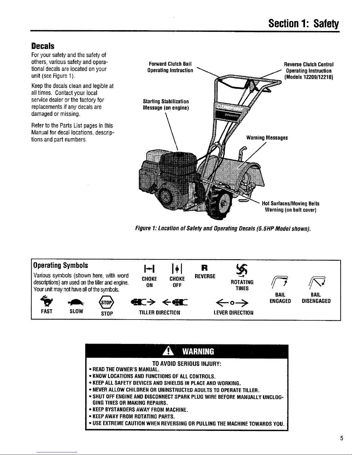
Decals
Foryour safety and the safetyof
others, various safety andopera-
tional decals arelocated on your
unit (seeFigure1).
Keepthe decals clean and legibleat
all times. Contact your local
servicedealer orthe factory for
replacementsif any decals are
damagedor missing.
Referto the Parts List pagesin this
Manualfor decallocations, descrip-
tions andpart numbers.
ForwardClutchBail
OperatingInstruction
StartingStabilization
Message (onengine)
WarningMessages
ReverseClutchControl
OperatingInstruction
(Models12209/12210)
HotSurfaces/MovingBelts
Warning(onbeltcover)
Figure1: LocationofSafetyand OperatingDecals(5.5HP Model shown),
OperatingSymbols I"1 I÷l
Various symbols (shown here,with word CHOKE CHOKE REVERSE
descriptions)areusedonthetillerandengine. ON OFF
Yourunitmaynothaveallofthesymbols.
FAST SLOW STOP TILLER DIRECTION
R
ROTATING
TINES
LEVERDIRECTION
BAIL
ENGAGED
BAIL
DISENGAGED
TO AVOID SERIOUS INJURY:
• READTHEOWNER'SMANUAL.
• KNOWLOCATIONSAND FUNCTIONSOF ALLCONTROLS,
• KEEPALLSAFETYDEVICESAND SHIELDSIN PLACEANDWORKING.
• NEVERALLOWCHILDRENOR UNINSTRUCTEDADULTSTO OPERATETILLER.
• SHUTOFFENGINEANDDISCONNECTSPARKPLUGWIRE BEFOREMANUALLYUNCLOG-
GINGTINES OR MAKINGREPAIRS.
• KEEPBYSTANDERSAWAYFROM MACHINE.
• KEEPAWAYFROM ROTATINGPARTS.
• USEEXTREMECAUTIONWHENREVERSINGORPULLINGTHEMACHINETOWARDSYOU.
Assembly
To prevent personal injury or property
damage, do not start the engine until
all assembly steps are complete and
you have read and understand the
satety andoperatinginstructionsin this
mannal.
Introduction
Carefullyfollow these assemblysteps to
correctly prepareyour tiller for use. It is
recommendedthat you read this Section
in its entirety before beginningassembly.
NOTE:Various tiller modelsare presented
in this Manual. Use only the information
appropriate for your tiller model.
Inspectunit
Inspectthe unit and cartonfor damage
immediately afterdelivery, Contactthe
carrier (trucking company) if you find or
suspect damage. Inform them of the
damageand request instructions for filing
a claim. To protect your rights, put your
claim inwriting and mail a copy to the
carrier within 15days after the unit has
beendelivered.Contact us atthe factory if
you needassistancein this matter.
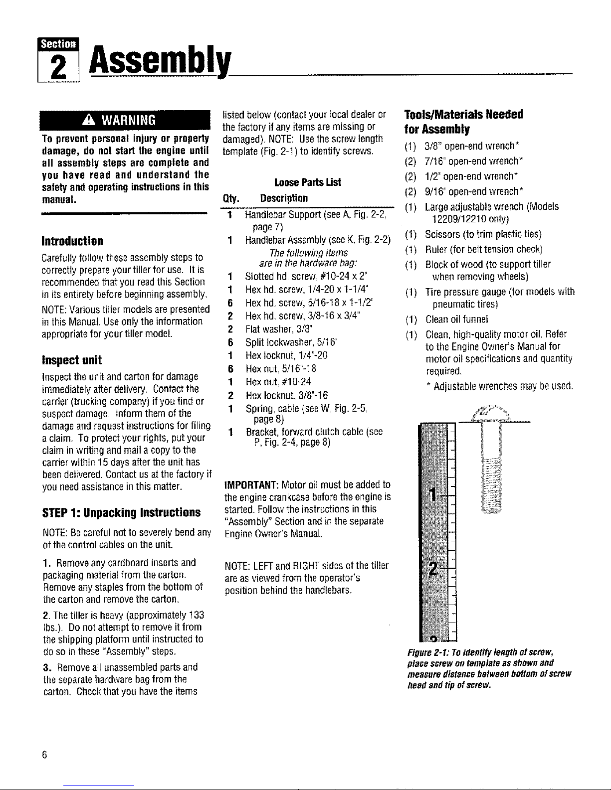
STEP1: Unpacking Instructions
NOTE:Becareful notto severely bendany
of the control cableson the unit.
1. Removeanycardboard inserts and
packagingmaterialfrom the carton.
Removeany staplesfrom the bottom of
the carton andremove the carton.
2.Thetiller is heavy(approximately 133
Ibs.). Do not attempt to remove itfrom
the shipping platform until instructed to
do so in these "Assembly" steps.
3. Remove all unassembledpartsand
theseparate hardwarebagfrom the
carton. Checkthatyou havethe items
listed below (contact your local dealeror
the factory if anyitems are missing or
damaged). NOTE: Usethe screw length
template (Fig. 2-1)to identify screws.
LooseParts List
Qty. Description
1 HandlebarSupport (seeA, Fig.2-2,
page7)
1 HandlebarAssembly(seeK, Fig.2-2)
Thefollowing items
are in the hardware bag:
1 Slotted hd. screw,#10-24 x 2"
1 Hexhd. screw, 1/4-20 x 1-1/4"
6 Hex hd.screw, 5/16-18 x 1-1/2"
2 Hex hd.screw, 3/8-16 x 3/4"
2 Flatwasher, 3/8"
6 Split Iockwasher,5/16"
1 Hexlocknut, 1/4"-20
6 Hexnut, 5/16"-18
1 Hex nut, #10-24
2 Hexlocknut, 3/8"-16
1 Spring, cable(seeW, Fig. 2-5,
page8)
1 Bracket, forward clutch cable (see
P, Fig. 2-4, page8)
IMPORTANT:Motor oil must be addedto
the engine crankcasebeforethe engineis
started. Followthe instructions in this
"Assembly" Section and in the separate
Engine Owner's Manual
NOTE:LEFTand RIGHTsidesof the tiller
are asviewed from the operator's
position behindthe handlebars.
Tools/MaterialsNeeded
for Assembly
(1) 3/8" open-end wrench*
(2) 7/16" open-end wrench*
(2) 1/2" open-end wrench*
(2) 9/16°open-end wrench*
(1) Large adjustablewrench (Models
12209/12210 only)
(1) Scissors (to trim plastic ties)
(1) Ruler (for belttension check)
(1) Block of wood (to support tiller
when removing wheels)
(1) Tire pressure gauge(for modelswith
pneumatictires)
(1) Cleanoil funnel
(1) Clean.high-quality motoroil. Refer
to the Engine Owner's Manualfor
motor oil specifications and quantity
required,
Adjustable wrenches maybe used.
Figure2-1: Toidentifylengthofscrew,
placescrewontemplateasshownand
measuredistancebetweenbottomofscrew
headandtip ofscrew,
6
Section2: Assembly
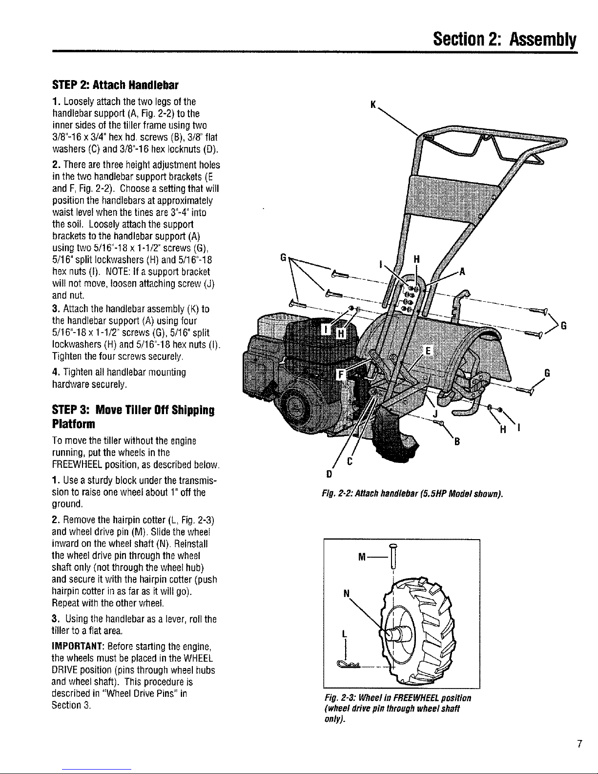
STEP2: AttachHandlebar
1. Looselyattach thetwo legs ofthe
handlebar support (A, Fig. 2-2) to the
inner sidesof the tiller frame using two
3/8"-16 x 3/4" bexhd, screws (B), 3/8"flat
washers (C)and 3/8"-16 bex Iocknuts(D).
2. Therearethree heightadjustment holes
in the two handlebar support brackets(E
and F,Fig.2-2). Chooseasetting that will
positionthe handlebarsat approximately
waist levelwhenthe tines are 3"-4"into
the soil. Loosely attachthe support
brackets to the handlebarsupport (A)
using two 5/!6"-18 x 1-1/2" screws (G),
5/16" split Iockwashers(H) and 5/16"-18
bex nuts (I). NOTE:If a support bracket
will not move,loosen attaching screw (J)
and nut.
3. Attach the handlebarassembly (K)to
the handlebar support (A) using four
5/16"-18 × 1-1/2" screws (G), 5/16" split
Iockwashers (H) and5/16"-18 hex nuts (I).
Tighten thefour screws securely.
4. Tighten all handlebarmounting
hardwaresecurely.
STEP3: Move Tiller Off Shipping
Platform
To movethe tiller without the engine
running, putthe wheels in the
FREEWHEELposition, as described below,
1. Useasturdy block under the transmis-
sion to raiseone wheel about !" off the
G
J
"'_B H
C
D
Fig.22: Attachhandlebar(5,5HPModelshown).
G
ground,
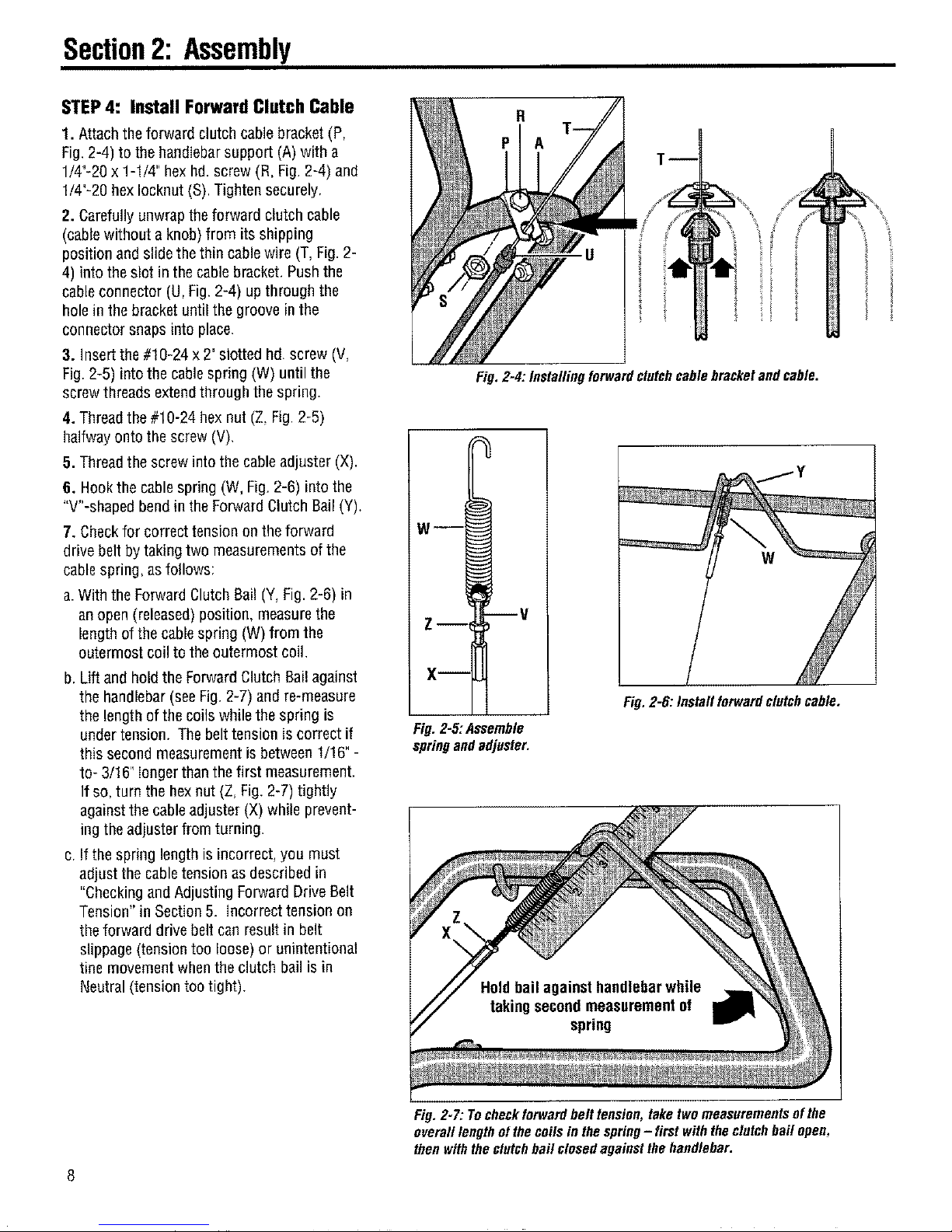
2. Removethehairpin cotter (L, Fig.2-3)
and wheeldrive pin (M). Slidethe wheel
inward on the wheel shaft (N). Reinstall
the wheel drive pin through the wheel
shaft only (not through the wheel hub)
and secureit with the hairpin cotter (push
hairpin cotter in as far as it will go).
Repeatwith the other wheel.
3. Usingthe handlebar asa lever, rollthe
tiller to afiat area.
IMPORTANT:Before starting the engine,
the wheels must be placedin the WHEEL
DRIVEposition (pins through wheel hubs
and wheel shaft). This procedure is
described in "Wheel Drive Pins" in
Section 3,
I
N0
\
L
Fig. 2-3: Wheel in FREEWHEELposition
(wheel drivepin throughwheel shaft
only).
Section2: Assembly
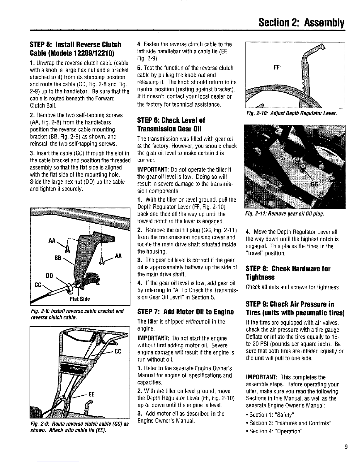
STEP4: InstallForwardClutchCable
1. Attachthe forward clutch cablebracket (P,
Fig. 2-4) to the handlebarsupport (A) with a
1/4"-20 x 1-1/4" hexhd. screw (R, Fig. 2-4) and
1/4"-20 hexIocknut (S).Tighten securely,
2. Carefully unwrapthe forward clutch cable
(cablewithout a knob) from its shipping
position andslidethe thin cablewire (T, Fig. 2-
4) into the slot inthe cable bracket, Push the
cableconnector (U, Fig. 2-4) upthrough the
hole inthe bracket until the groove in the
connector snaps into place.
3. Insert the#10-24 x 2" slotted hd. screw (V,
Fig.2-5) into the cablespring (W) until the
screwthreads extendthrough the spring.
4. Threadthe #10-24 hex nut (Z, Fig,2-5)
halfwayonto the screw (V),
5. Threadthe screw into the cableadjuster (X).
6. Hook the cablespring (W, Fig. 2-6) into the
"V"-shaped bendin the Forward Clutch Bail (Y).
7. Checkfor correct tension on the forward
drive belt by taking two measurementsof the
cablespring, asfollows:
a.With the Forward Clutch Bail (Y, Fig.2-6) in
an open(released)position, measurethe
length of the cable spring (W) from the
outermost coil to theoutermost coil,
b. Lift andhold the ForwardClutch Bail against
the handlebar(seeFig. 2-7) and re-measure
the length ofthe coilswhile the spring is
under tension. The belttension is correct if
this secondmeasurement is between 1/!6"-
to- 3/16" longerthanthe first measurement.
If so,turn the hex nut (Z, Fig.2-7) tightly
againstthe cableadjuster (X) while prevent-
ing theadjuster from turning.
c. Ifthe spring length is incorrect, you must
adjust the cabletension as describedin
"Checkingand Adjusting Forward Drive Belt
Tension" in Section 5. Incorrect tension on
the forward drive belt can result in belt
slippage(tension too loose)or un}ntentional
tine movement whenthe clutch bail is in
Neutral (tensiontoo tight).
R
Fig. 2-4: Installing forward clutchcable bracket andcable.
w--[
Z-- V
X--
Fig.2-5:Assemble
springandadjuster.
Fig.2-6. Installforwardclutchcable.
Fig. 2-7: Tocheckforward belt tension, take two measurementsofthe
overall lengthof thecoils in the spring- first with theclutchbail open,
then withtheclutchbait closedagainstthe handlebar.
Section2: Assembly
STEP5: Install ReverseClutch
Cable(Models12209/12210)
1. Unwrapthe reverse clutch cable (cable
with aknob, a largehex nut anda bracket
attachedto it) from its shipping position
and routethe cable (CC,Fig.2-8 andFig.
2-9) upto the handlebar. Besurethat the
cable is routed beneaththe Forward
Clutch Bail.
2. Removethe two self-tapping screws
(AA,Fig.2-8) from the handlebars,
position the reversecable mounting
bracket(BB,Fig. 2-8) as shown, and
reinstall thetwo self-tapping screws.
3. Insertthe cable (CC)through the slot in
the cablebracketand position thethreaded
assembly sothat the flat side is aligned
with the flatside of the mounting hole.
Slide the largehex nut (DD) up thecable
and tighten it securely.
Flat Side
Fig. 2-8: Install reverse cable bracketand
reverseclutchcable.
Fig.2-8: Routereverseclutchcable(CC)as
shown.Attachwithcabletie (EE).
4. Fastenthereverseclutch cable to the
left side handlebarwith a cabletie (EE,
Fig. 2-9).
5. Testthefunction of the reverse clutch
cableby pulling the knob out and
releasingit. Theknob should return to its
neutral position (resting against bracket).
If it doesn't, contact your local dealeror
the factory for technical assistance.
STEP6: CheckLevelof
TransmissionGearOil
Thetransmission was filled with gear oil
atthe factory, However, you should check
the gear oil level to makecertain it is
correct.
IMPORTANT:Do not operatethe tiller if
the gear oil level is low. Doing so will
result in severedamageto the transmis-
sion components.
1. With the tiller on levelground, puII the
Depth RegulatorLever (FF,Fig.2-10)
back andthen a!l the way up until the
lowest notch in the lever is engaged.
2. Removethe oil fill plug (GG,Fig, 2-11)
from the transmission housing cover and
locate the main drive shaft situated inside
the housing.
3. The gear oil levelis correct if the gear
oil isapproximately halfway upthe side of
the main drive shaft.
4. Ifthe gear oil levelis low, add gear oil
by referringto "A. To Checkthe Transmis-
sion GearOilLevel" in Section 5,
STEP7: AddMotorOilto Engine
Thetiller is shipped withoutoil in the
engine.
IMPORTANT: Donot start the engine
without first adding motoroiL Severe
engine damagewill result if the engine is
run without oil.
1. Referto the separate EngineOwner's
Manual for engine oil specificationsand
capacities,
2. With the tiller on levelground, move
the Depth RegulatorLever (FF,Fig. 2-10)
up or down until the engineis level.
3. Add motor oil as described in the
Engine Owner's Manual.
Fig. 2-10: Adjust DepthRegulator Lever.
Fig. 2-11: Removegear oil fill plug.
4. Movethe Depth Regulator Lever all
the way down until the highest notch is
engaged. This placesthe tines in the
"travel" position.
STEP8: Check Hardware for
Tightness
Checkallnutsandscrewsfortightness,
STEP9: CheckAirPressurein
Tires(unitswith pneumatictires)
If the tires are equipped with air valves,
checkthe air pressure with atire gauge.
Deflateor inflatethe tires equallyto 15-
to-20 PSI (pounds per square inch). Be
surethat both tires areinflated equally or
the unit will pull to one side.
IMPORTANT: This completesthe
assembly steps. Beforeoperating your
tiller, makesureyou readthe following
Sections in this Manual,as well as the
separateEngineOwner'sManual:
* Section 1: "Safety"
• Section 3: "Featuresand Controls"
• Section 4: "Operation"
9
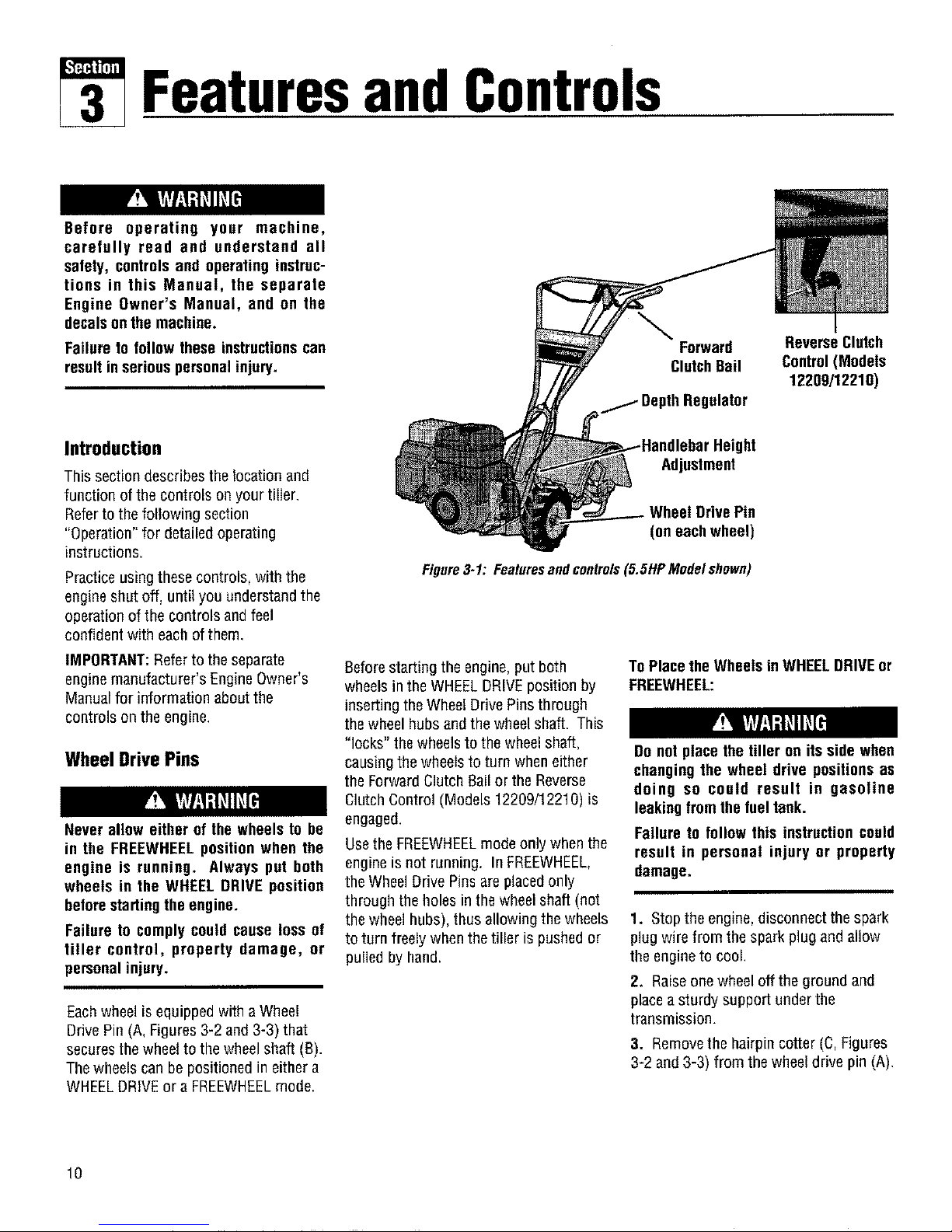
FeaturesandControls
Before operating your machine,
carefully read and understand oil
safety, controls and operating instruc-
tions in this Manual, the separate
Engine Owner's Manual, and on the
decalsonthe machine.
Failure to follow these instructionscan
resultin serious personalinjury.
Introduction
This section describes the location and
function of the controls on your tiller.
Refer to the following section
"Operation" for detailedoperating
instructions.
Practice usingthese controls, with the
engine shut off, until you understandthe
operation of the controls andfeel
confident with eachof them.
IMPORTANT:Refer to the separate
engine manufacturer's EngineOwner's
Manualfor information about the
controls on the engine.
Wheel Drive Pins
Never allow either of the wheelsto be
in the FREEWHEELposition when the
engine is running, Always put both
wheels in the WHEEL DRIVE position
beforestartingthe engine.
Failure to comply could cause loss of
tiller control, property damage, or
personalinjury.
Eachwheel is equippedwith a Wheel
Drive Pin(A, Figures 3-2 and 3-3) that
securesthe wheel to the wheel shaft (B).
Thewheels can be positionedin either a
WHEELDRIVEor aFREEWHEELmode.
\
Forward Reverse Clutch
ClutchBail Control(Models
12209/12210)
ulator
Adjustment
DrivePin
(on eachwheel)
Figure3-1: Featuresand controls(5.5HP Model shown)
Beforestarting the engine, put both
wheels inthe WHEELDRIVEposition by
inserting theWheel Drive Pins through
thewheel hubs and the wheelshaft. This
"locks" the wheels to the wheelshaft,
causing thewheelsto turn when either
the Forward Clutch Bailor the Reverse
Clutch Control (Models 12209/1221O)is
engaged.
Usethe FREEWHEELmodeonly when the
engine is not running. In FREEWHEEL,
the WheelDrive Pinsare placedonly
through the holes in the wheel shaft (not
the wheel hubs), thus allowing the wheels
to turn freely whenthe tiller is pushedor
pulled by hand,
To Place theWheels in WHEELDRIVEor
FREEWHEEL:
Do notplace the tiller on its side when
changing the wheel drive positionsas
doing so could result in gasoline
leakingfromthe fuel tank°
Failure to follow this instructioncould
result in personal injury or property
damage.
1. Stop the engine, disconnect the spark
plugwire from the spark plugand allow
the engineto cool,
2. Raiseonewheel off the ground and
placea sturdy support under the
transmission.
3. Removethe hairpin cotter (C, Figures
3-2 and3-3) from the wheeldrive pin (A).
10
Section3: FeaturesandControls
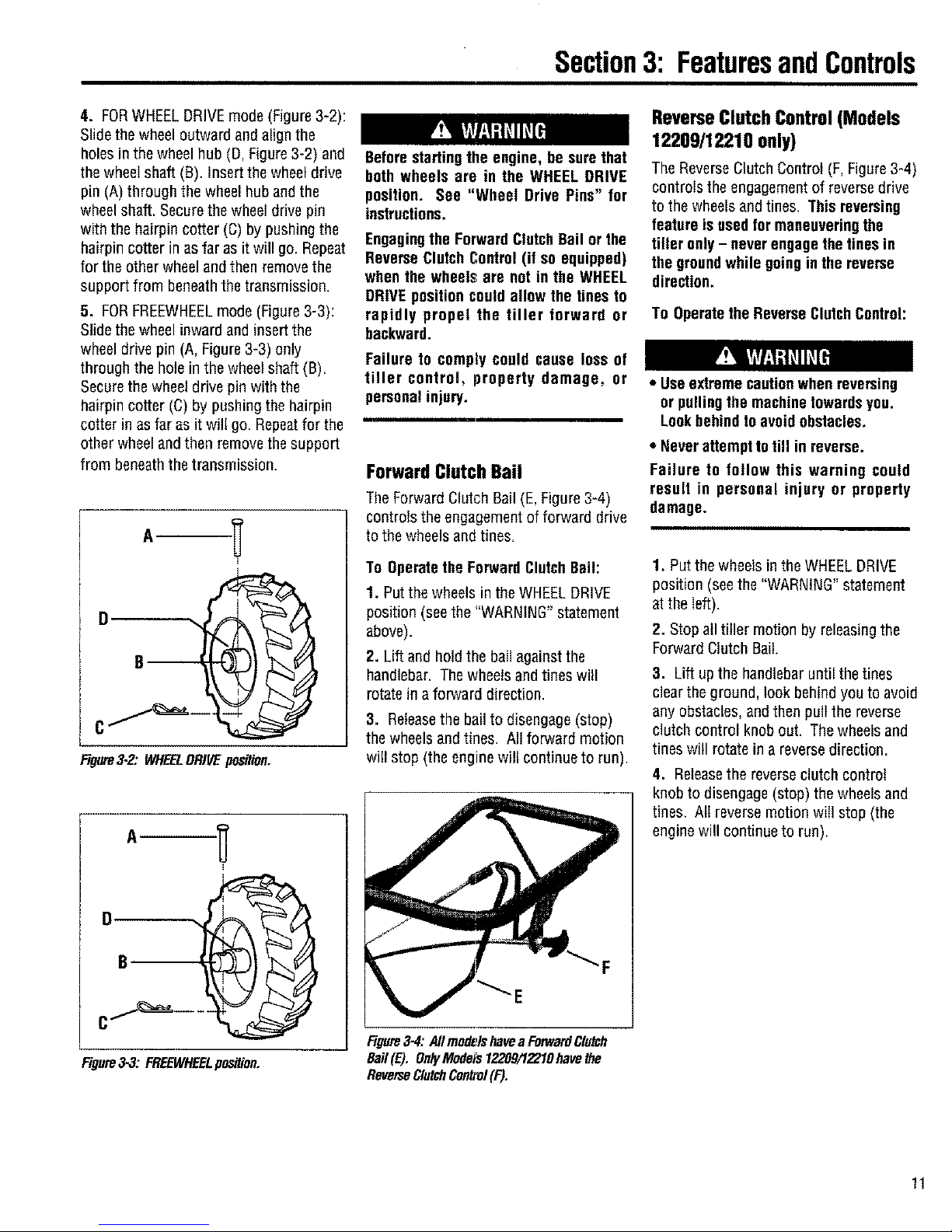
4. FORWHEELDRIVEmode (Figure3-2):
Slidethe wheeloutward andalign the
holes in the wheel hub (D,Figure 3-2) and
the wheeIshaft (B). Insert the wheel drive
pin (A)through the wheel hub andthe
wheelshaft. Securethe wheeldrive pin
with the hairpin cotter (C) by pushingthe
hairpin cotter inas far as it will go. Repeat
for the other wheel andthen removethe
support from beneaththe transmission.
5. FORFREEWHEELmode (Figure3-3):
Slide the wheelinward and insertthe
wheel drive pin (A, Figure3-3) only
through the hole in the wheelshaft (B).
Securethe wheeldrive pinwith the
hairpin cotter (C)by pushingthe hairpin
cotter in as far as it will go. Repeatfor the
other wheel andthen remove the support
from beneaththe transmission.
0 1
Figure3.2: WHEELDRIVEposiUon.
Figure3-3: FREEWHEELposition.
Beforestartingthe engine, be surethat
bothwheels are in the WHEELDRIVE
position. See "Wheel Drive Pins" for
instructions.
Engagingthe ForwardClutchBailor the
ReverseClutchControl(if so equipped)
when the wheels are notin the WHEEL
DRIVEpositioncould allew the tines to
rapidly propel the tiller forward or
backward.
Failure to comply could cause loss of
tiller control, property damage, or
personalinjury.
Forward Clutch Bail
TheForwardClutchBail(E,Figure3-4)
controlstheengagementof forwarddrive
tothewheelsandtines.
To Operatethe ForwardClutchBail:
1. Putthe wheels in the WHEELDRIVE
position(seethe "WARNING" statement
above).
2. Lift and hold the bail against the
handlebar. Thewheels and tines will
rotate ina forward direction.
3. Releasethe bailto disengage(stop)
the wheels andtines. All forward motion
will stop (the engine will continue to run).
Figure3-4:AllmodelshaveaFonverdClutch
Bail(E). OnlyModets1220971_I0havethe
ReverseClutchControl(F).
ReverseClutchControl(Models
12209/12210 only)
The ReverseClutchControl (F, Figure3-4)
controls the engagementof reversedrive
to the wheels and tines. Thisreversing
feature is usedformaneuveringthe
tiller only- neverengagethetines in
the groundwhile going inthe reverse
direction.
To Operatethe Reverse ClutchControl:
• Use extremecautionwhen reversing
or pullingthe machinetowardsyou.
Lookbehind toavoidobstacles.
• Neverattemptto till in reverse.
Failure to follow this warning could
result in personal injury or property
damage.
1. Putthe wheels in the WHEELDRIVE
position (seethe "WARNING"statement
atthe left).
2. Stop all tiller motion by releasingthe
Forward Clutch Bail.
3. Lift up the handlebaruntil the tines
clearthe ground, look behindyouto avoid
any obstacles,and then pull the reverse
clutch control knobout. The wheelsand
tines will rotatein a reversedirection.
4. Releasethe reverseclutch control
knob to disengage (stop) the wheelsand
tines. All reversemotion will stop (the
engine will continueto run).
11
 Loading...