

Page 1

GARDEN WAY
_ TRO_BILT TM
OWNER'SMANUAL
Tiller/Edger
Owner's
SAI
;T!
read this
manual
• Safety
• Assembly
• Features and Controls
• Operation
• Maintenance
• Parts List
Model
12215
GARDEN WAY INCORPORATED
Page 2
DearOwner:
Congratulationson your purchaseof a Tiller/Edgerwith
EdgerAttachment. It hasbeendesigned, engineeredand
manufactured to giveyou the best possible dependabilityand
performance.
Pleasecarefully readthis Manualwhich provides information
on howto safely and easilyset-up, operateand maintain your
machine. Besure thatyou and any other operators carefully
follow therecommendedsafety practices at all times. Failure
todo so could result in personal injury orproperty damage.
If you should ever have any problems or questions, please
contact your localauthorized service dealer or call the Factory.
Seethe backcover of this Manualfor Customer Serviceinfor-
mation.
Wewant to be sure that you arecompletely satisfied at all
times.
See Back Cover for
Customer Service Information
SafetyAlert Symbol
_ his is a safety alert symbol. It is used in this
sagescould result in personal injury or property damage.
manualand on the unit to alert youto potential haz-
ards. Whenyou seethis symbol, readand obeythe
messagethat follows it. Failureto obeysafety mes-
Table of Contents
SECTION1: SAFETY........................................... 3
Training......................................................................... 3
Preparation................................................................... 3
Operation...................................................................... 3
Maintenance/Storage.................................................... 4
SECTION2: ASSEMBLY........................................ 5
UnpackingInstructions ............................................... 5
Assembly Steps.......................................................... 5
SECTION3: FEATURESANDCONTROLS..................... 7
SECTION4: OPERATION...................................... 8
Pre-start Preparation.................................................. 8
Stopping and Startingthe Engine............................... 8
Tilling and Cultivating ................................................. 9
Using the EdgerAttachment....................................... 10
Attachments ............................................................... 10
SECTION5: MAINTENANCE.................................. 11
RequiredMaintenanceSchedule ................................ 11
EquipmentMaintenance............................................. 11
EngineMaintenance................................................... 11
TineRemovaland Installation..................................... 12
Storage....................................................................... 13
Troubleshooting.......................................................... 14
Safetyand Operating Decals....................................... 14
PARTSLIST ..................................................... 15
INDEX............................................................ 19
CUSTOMERSERVICEINFORMATION.............. BACKCOVER
This machine meets voluntary safety standard
B71.8 - 1996, which is sponsored by the Outdoor
Power Equipment Institute, Inc., and is published by
the American National Standards Institute.
WARNING
The engine exhaust from this productcontains chemi-
cals known to the State of California to cause cancer,
birth defects or other reproductive harm.
2
TOAVOIDINJURY:
• READTHEOPERATOR'SMANUAL.
• KNOWLOCATIONANDFUNCTIONOFALL CONTROLS.
• KEEPALL SAFETYDEVICESAND SHIELDS IN PLACEAND
WORKING,
• NEVERALLOWCHILDRENOR UNINSTRUCTEDADULTSTO
OPERATEMACHINE.
• SHUT OFF ENGINEAND DISCONNECTSPARKPLUG WIRE
BEFORE MANUALLY UNCLOGGING TINES OR MAKING
REPAIRS,
• KEEPBYSTANDERSAWAYFROMMACHINE.
• KEEPAWAYFROMROTATINGPARTS.
• USEEXTREMECAUTIONWHEN REVERSINGOR PULLING
THEMACHINETOWARDSYOU.
Page 3
Safety
SPARKARRESTERWARNINGTO RESIDENTSOFCALIFORNIAAND SEVERALOTHERSTATES
UnderCalifornia law, and under the laws of severalother states, you are not permitted to operatean internalcombustion engine
using hydrocarbon fuels on anyforest, brush, hay,grain, or grass covered land;or land covered by any flammable agricultural crop
without an enginespark arrester in continuous effectiveworking order.
Theengineon the unit isan internalcombustion enginewhich burns gasoline, a hydrocarbon fuel, and must be equippedwith a
spark arrester muffler in continuous effective working order. Thespark arrester must be attachedto the engine exhaust system in
such a mannerthat flames or heatfrom the system will not ignite flammable material. Failureof the owner/operator of the unit to
comply with this regulation is a misdemeanor under California law (and other states) and may also bea violation of other state
and/or federalregulations, laws,ordinances or codes. Contactyour local fire marshal or forest servicefor specific information
about which regulations apply in your area.
TRAINING
• Readthis Owner's Manual and the sep-
arateEngineOwner'sManualvery care-
fully beforeoperating this equipment. Be
completely familiar with the controls and
the proper useof the equipment. Know
how to stop the unit and disengagethe
controls quickly. A replacementManual
is availableby contacting your authorized
dealeror the Factory.
• Neverallow children or untrained
adults to usethis equipment. Let adults
operatethe unit only if instructed
properly.
• Keepthe areaof operation clear of all
persons, particularly small children and
pets. Keepbystanders at least 25 feet
from the areaof operation.
• Keepin mind that the operator or user
is responsible for accidents or hazards
occurring to other people,their property
andthemselves.
• Familiarizeyourself with all of the
safety and operatingdecals onthis equip-
ment and on anyof itsattachments or
accessories.
• Do not run engine in an enclosedarea.
Engineexhaustcontains carbon
monoxide gas, a deadlypoison that is
odorless, colorless, and tasteless. Do not
operatethis equipment near buildings,
windows, or air conditioning equipment.
• Do not allow handsor anyother part of
the bodyor clothing nearthe rotating
tines or near anyother moving part. The
tines begin to rotateforward oncethe
engine is startedand the Throttle/Tines
Leveris squeezed. The tines continue to
rotate until theoperator releasesthe
Throttle/Tines Lever.
• Before inspectingor servicing any part
of the equipment,shut off engine,make
sure all moving parts havecome to a
completestop, then disconnect spark
plug wire from spark plug and move wire
awayfrom the plug.
• Do notoperatethis equipment ifyou are
underthe influenceof alcohol, medication,
or whenyou aretired or ill.
PREPARATION
• Thoroughly inspectthe areawhere the
equipment is to be usedand removeall
foreign objects.
• Make sure that the Throttle/Tines Lever
is releasedand is in the neutral position
beforeyou begin to start the engine.
• Donot operate the machinewithout
wearingadequateouter garments. Avoid
loosegarments orjewelry that could get
caught in moving parts of the machine or
its engine.
• Donot operate the equipment when
barefoot or when wearing sandals,
sneakers,or similar lightweight footwear.
Wearprotective footwear that will protect
your feet and improve footing on all
surfaces.
• Wearapprovedsafety glasses when
operatingthis equipment. Theoperation
of any powered machine canresult in for-
eign objects being thrown by high-speed
rotating parts.
• Donot till near underground electric
cables,telephone lines, pipes, or hoses.
If in doubt, contact your utility or tele-
phone company to locate underground
services.
• Handlefuel with care. It is highly
flammable and has explosivevapors.
Takethese precautions:
a. Usean approved fuel container.
b. Addfuel before starting the engine.
Neverremovethe capof the fuel tank
or add fuel while the engine is running
or when the engine is hot. Operators
shall not smoke.
c. Keepmatches, cigarettes, cigars,
pipes, open flames, andsparks away
from the fuel tank and fuel container.
d. Fill fuel tank outdoors and with
extremecaution. Neverfill fuel tank
when indoors. Usea funnel or spout
to prevent spillage.
e. Replaceall fuel tank and fuel container
capssecurely.
f. If fuel is spilled, do not attempt to start
the engine,but movethe machineaway
from the area of spillageand avoid cre-
ating any source of ignition until fuel
vapors havedissipated.
• Nevermake adjustmentsto your equip-
ment when the engine is running or spark
plug wire is connected(unless specifically
recommendedin Owner'sManual).
OPERATION
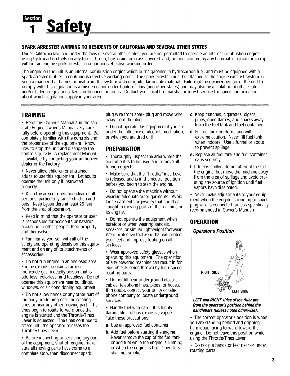
Operator's Position
LEFTand RIGHTsides of the tiller are
from the operator'spositionbehindthe
handlebars(unlessnoted otherwise).
• Thecorrect operator's position iswhen
you arestanding behind and gripping
handlebar,facing forward toward the
engine. Do not leavethis position while
using the Throttle/Tines Lever.
• Do not put handsor feet nearor under
rotating parts.
Page 4
Section1: Safety
• Exerciseextreme caution when on or
crossing gravel drives, walks or roads.
Stay alert for hidden hazardsor traffic.
Do not carry passengers.
• After striking a foreign object, stop the
engine,let all moving parts come to a
completestop, disconnectthe spark plug
wire and prevent it from touching the
spark plug, then carefully inspectthe
machinefor damage. Repairthe damage
beforerestarting andoperating the
machine.
• Exercisecaution to avoidslipping or
falling.
• If the machine should start to vibrate
abnormally,stop theengine. Disconnect
the spark plug wire and prevent it from
touching the plug. Check immediately for
the cause. Vibration is generallya
warning of trouble. Fixthe problem
beforeusing the equipment again.
• Stop the engine, disconnect thespark
plug wire and prevent it from touching the
spark plug wheneveryou leavethe equip-
ment, beforeunclogging the tines, or
when making anyrepairs, adjustments or
inspections.
• Takeall possible precautions when
leavingthe machine unattended. Always
stop the engine. Disconnect the spark
plug wire and prevent it from touching the
plug.
• Beforecleaning, repairing, or
inspecting, stop the engineand make
certain all moving parts havestopped.
Disconnectthe spark plug wire and
prevent it from touching the spark plug to
avoidaccidentalstarting.
• Neveroperate equipment without
proper guards, plates, or other protective
safety devices in place.
• Do not run the engine in an enclosed
area. The exhaust fumes from the engine
contain extremely dangerouscarbon
monoxide gas. Thisgas is colorless,
odorless,tastelessand deadlypoisonous.
• Keepchildren and pets away.
• Beawarethat theequipment may unex-
pectedlybounce upwardorjump forward
if the tines should strike extremelyhard
packedsoil, frozen ground, or buried
obstacles such as largestones,roots or
stumps. If you are in doubt about the
tilling conditions, always use the fol-
lowing operating precautionsto assist
you in maintaining control of the
equipment:
a. Standbehind the equipment, using
both handson the handlebars. Relax
your arms, but usea securehand
grip.
b. Start tilling at shallow depths, working
graduallydeeper with each pass.
c. Clearthe tilling areaof all largestones,
roots, and other debris.
d. In an emergency,stop the tines by
releasingtheThrottle/Tines Leveron
the handlebar. To stop the engine,
move the engineOn/Offswitch to OFE
• Donot overload the machine'scapacity
by attempting to till too deeplyattoo fast
a rate.
• Neveroperatethe equipment on slip-
pery surfaces. Look behind and usecare
when backing up.
• Donot operate the equipment on a
slopethat is too steep for safety. When
on slopes, slow down and makesure you
havegood footing.
• Neverallow bystandersnear the unit.
• Onlyuse attachmentsand accessories
that are factory-approved.
• Neveroperatethe equipment without
good visibility or good light.
• Neveroperatethe unit if you aretired,
or under the influence of alcohol, drugs,
or medication.
• Donot tamper with the engine gov-
ernor settings on the machine;the gov-
ernor controls the maximum safeoper-
ating speedand protects the engine and
all other moving parts from damage
causedby engine overspeed. Authorized
serviceshall be sought if a problem
exists.
• Do not touch engineparts which may
be hot from operation. Allow parts to
cool before inspecting, cleaningor
repairing.
• Remember:you can stop the tines by
releasingthe Throttle/Tines Lever. Move
theengine On/Off switch to OFFto shut
theengine off.
• Nevertransport this machinewhen the
engine is running.
• Terminalsand non-insulated electrical
parts shall be protected against shorting
during normal servicing, refueling or
lubrication.
• Useextreme caution when reversing or
pulling the machinetoward you.
• Start the engine carefully according to
instructions and with feet well awayfrom
thetines.
MAINTENANCE/STORAGE
• Keepthe tiller, attachments and acces-
sories in safeworking condition.
• Checkall nuts, bolts, and screws atfre-
quent intervalsfor proper tightness to be
sureequipment is in safeworking
condition.
• Neverstore equipment with fuel infuel
tank inside a building where fumes may
reachan open flame or spark (hot water
and spaceheaters,furnaces, clothes
dryers, stoves, electric motors, etc.).
• Allow the engineto cool beforestoring
theequipment.
• Keep the engine freeof grass, leaves,
or greaseto reducethe chance of afire
hazard.
• Store gasolinein a cool, well-ventilated
area,safely awayfrom anyspark- or
flame-producing equipment. Storegaso-
line in an approvedcontainer,safelyaway
from the reachof children.
• Neverperform maintenancewhen
engine is running or spark plug wire is
connectedunless instructed to do so.
• If fuel tank must be drained,do so
outdoors.
• Follow manufacturer's recommenda-
tions for safe loading, unloading,
transport and storageof machine.
4
Page 5
!,'£4"4U;_
2 Assembly
To prevent personal injury or property
damage, donot startthe engineuntil all
assembly steps are complete and you
haveread andunderstandthe safetyand
operatinginstructionsin this manual.
INTRODUCTION
Readthese instructions in their entirety
beforeyou attempt to assembleor
operateyour newequipment.
TheBorder/EdgerAttachment (H, Figure
5) doesnot needto be installed until you
are readyto doedging projects (refer to
instructions in this Section).
IMPORTANT:Thecorrect mixture of
unleadedautomotive gasolineand two-
cyclemotor oil (a 24:1 ratio of gasoline to
two-cycle oil) must be addedto the fuel
tank before starting theengine. See
instructions in this Section.
UNPACKINGINSTRUCTIONS
1. Inspect your machineimmediately. If
youfind or suspect damageto the carton
or contents, contact your local authorized
dealeror the Factoryfor assistance.
2. Removeany packing material. Check
for small parts beforediscarding the
packing material. Loose parts includethe
following:
(1) Wheel(for edging)
(1) EdgerTine
(2) *Long Bushings
(1) *Short Bushing
* Packedin a separateplastic bag.
3. Perform the assembly on a clean, level
surface. Becareful not to severely bend
anyof the control cables on the unit.
4. Beforestartingany assemblysteps,
disconnecttheengine sparkplugwire
from thesparkplug.
ASSEMBLYSTEPS
STEP 1: Unfold and
Adjust Handlebars
IMPORTANT: Becareful not to pinch any
wires or cables while unfolding and
adjusting the handlebars.
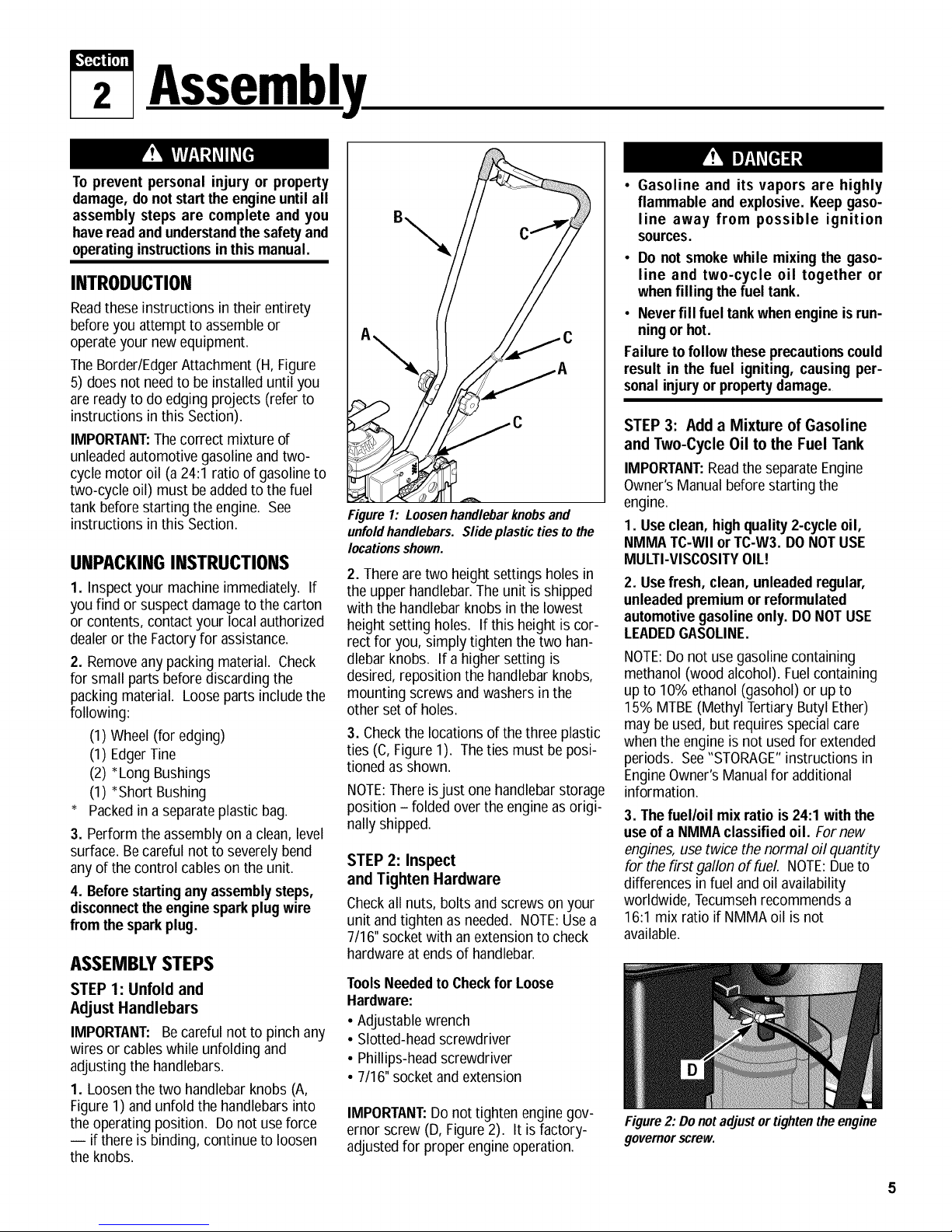
1. Loosen the two handlebarknobs (A,
Figure1) and unfold the handlebarsinto
the operatingposition. Donot useforce
-- if there is binding, continue to loosen
the knobs.
Figure 1: Loosenhandlebarknobsand
unfoldhandlebars. Slideplastic ties to the
locationsshown.
2. Thereare two height settings holes in
the upper handlebar.Theunit is shipped
with the handlebarknobs in the lowest
height setting holes. If this height is cor-
rect for you, simply tighten the two han-
dlebar knobs. If a higher setting is
desired, reposition the handlebar knobs,
mounting screws and washers in the
other set of holes.
3. Checkthe locations of thethree plastic
ties (C,Figure1). Theties must be posi-
tioned as shown.
NOTE:Thereisjust one handlebarstorage
position - folded over the engineas origi-
nally shipped.
STEP 2: Inspect
and Tighten Hardware
Checkall nuts, bolts and screws on your
unit and tighten as needed. NOTE:Usea
7/16" socketwith an extensionto check
hardwareat endsof handlebar.
ToolsNeededto Checkfor Loose
Hardware:
• Adjustable wrench
• Slotted-headscrewdriver
• Phillips-headscrewdriver
• 7/16"socket and extension
IMPORTANT:Do not tighten engine gov-
ernor screw (D, Figure 2). It isfactory-
adjustedfor proper engineoperation.
• Gasoline and its vapors are highly
flammable and explosive. Keepgaso-
line away from possible ignition
sources.
• Do not smoke while mixing the gaso-
line and two-cycle oil together or
whenfilling thefuel tank.
• Never fill fuel tankwhenengine is run-
ningor hot.
Failuretofollow theseprecautionscould
result in the fuel igniting, causing per-
sonalinjuryor propertydamage.
STEP 3: Add a Mixture of Gasoline
and Two-Cycle Oil to the Fuel Tank
IMPORTANT:Readthe separateEngine
Owner'sManual beforestarting the
engine.
1. Use clean, highquality2-cycle oil,
NMMATC-WII orTC-W3. DO NOTUSE
MULTI-VISCOSITYOIL!
2. Usefresh, clean, unleadedregular,
unleadedpremiumor reformulated
automotivegasolineonly. DONOTUSE
LEADEDGASOLINE.
NOTE:Do not usegasoline containing
methanol (wood alcohol). Fuel containing
up to 10% ethanol (gasohol) or up to
15% MTBE(Methyl Tertiary Butyl Ether)
may be used, but requires specialcare
whenthe engine is not usedfor extended
periods. See"STORAGE"instructions in
EngineOwner'sManualfor additional
information.
3. The fuel/oil mixratio is 24:1 with the
useofa NMMAclassifiedoil. Fornew
engines, use twice the normal oil quantity
for the first gallon of fuel. NOTE:Dueto
differences in fuel and oil availability
worldwide, Tecumsehrecommends a
16:1 mix ratio if NMMAoil isnot
available.
Figure2: Do not adjust or tightenthe engine
governorscrew.
Page 6

Section2: Assembly
Chart 1: FUEL MIXTURE
(Mixture Ratio is 24 parts gasolineto
1 part two-cycle oil)
U.S. Gas U.S. Oil
1 Gal. 5 oz.
2 Gal. 11 oz.
MetricPetrol Metric Oil
4 liters 167 ml
8 liters 333 ml
4. Donot mix fuel directly inenginefuel
tank. Always usea clean, safety-
approvedfuel container.
• ToMix:
A,
Fill a clean,approvedcontainer one
quarterfull with recommended
gasoline.
B.
Add recommended amount of oil per
Chart 1: FUELMIXTURE.
C.
Screw cap on container and shake
vigorously. Thenunscrew cap and
fill container with gasoline per
Chart 1: FUELMIXTURE. Screwon
capand shakeagain. Once mixed,
oil and gasoline will not separate.
Fill FuelTank:
1. Enginemustbe cool. Cleanarea
around fuel tank cap and removecap.
Inserta clean funnel into the fuel tank.
2. Slowly pour gasoline/oil mixture into
fueltank. Filltank no higher than 1/2"
from top of tank to allow for gasoline
expansion. Install fuel capand clean up
anyfuel spills.
STEP 4: To Make Borders and Edges,
Install the Edger Attachment
Tocreate borders or edges nearwalks,
driveways,flower beds, etc., you must
removethe four tine sections and install
the EdgerAttachment (this attachment
was supplied with the unit - see Page5).
To Installthe EdgerAttachment:
1. Gathertogether the following parts
(seeFigure4): (A) Border/EdgerTine; (B)
Long Bushing; (C) Border/EdgerWheel
and (D) Short Bushing.
2. Prop the machine carefullyon thefront
of thetubular carrying handle. Thework
surfaceshould befirm and flat. NOTE:
Usuallythe Border/EdgerTineis mounted
on the right-side of the unit for right-
handedpersons, and on the left-side of
the unit for left-handed persons.
3. Flip open the ring on the two ring lock
pins (E, Figures3 and 4) and remove the
ring lock pin on eachtine shaft.
IMPORTANT:The ring lock pin is under
spring tension - use carewhen removing
or replacingthe ring lock pin.
4. It is importantfor proper tilling perfor-
mancethat thetine sections be later rein-
stalled in their original patterns. Markthe
position of eachtine section(Left-Outer,
Left-Inner,etc.)beforeremovingthem.
Referto Figures3 and 9 for tine pattern
information. Seealso fine Removaland
Installation in Section 5.
5. Install the short bushing (D, Figure4)
on the right-hand or left-hand tine shaft.
Thenplacethe Border/Edgerwheel (C)on
Figure3: Removeringlockpinsandtines
frombothsidesofthetineshaft. Keepleft
andright-sidetinesseparatedandmarked
for easierreinstallation.
thesame shaft - the wheel hub should
facetoward the tiller. Insert the ring lock
pin through the rounded side of thetine
shaft and snapthe ring down overthe
shaft (seeDETAIL- RingLock Pin,
Figure4).
6. Slidethe long bushing (B)on the
opposite side shaft. Theninstall the
Border/Edgertine (A) and secure it with
the ring lock pin.
SeeSection 4 for instructions on using
the Border/EdgerAttachment.
See Tine Removaland Installation in Sec-
tion 5 for information on how to reinstall
thetines.
DETAIL- Ring Lock Pin
Thisside
out
Contact with rotating tines or other
moving parts can cause serious per-
sonalinjury.
Before installing or removing attach-
ments, or adjusting or servicing the
machine,stopthe engine, letall moving
parts come to a complete stop, discon-
nect the sparkplug wire and move the
wire away from the sparkplug.
E
Figure4: TheBorder/Edgertine (A)can be mountedon left or right
sidesofmachine(with longbushingB). The Border/Edgerwheel
(C) mountson the otherside (withshortbushingD).
Page 7
l,'t;t",gt_
3 Featuresand Controls
KNOWYOUREQUIPMENT
READ THIS OWNER'S MANUAL AND ALL SAFETY RULES BEFORE OPERATING YOUR EQUIPMENT. Know the
location and function of all features and controls on the equipment. Save this manual for future reference.
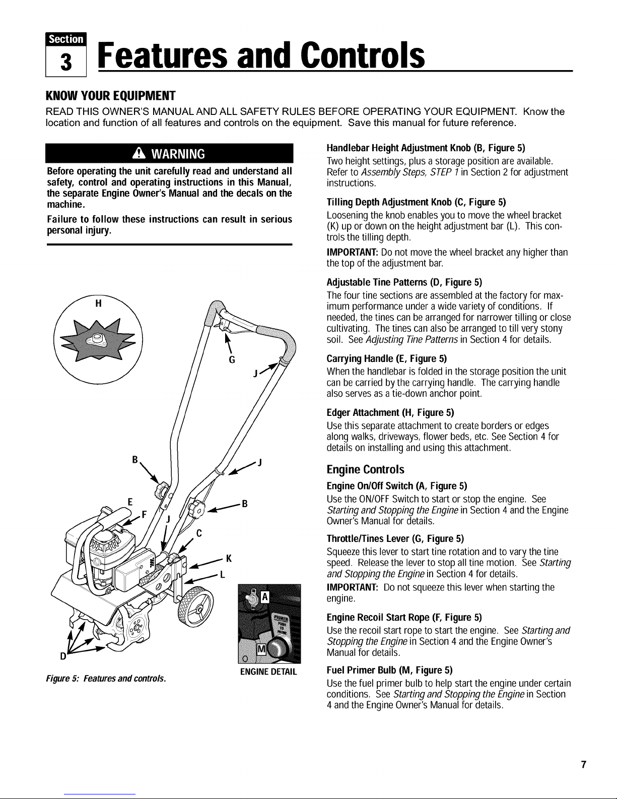
HandlebarHeightAdjustmentKnob(B, Figure 5)
Twoheight settings, plus a storage position are available.
Beforeoperatingthe unit carefully read and understandall
safety, control and operating instructionsin this Manual,
the separate EngineOwner'sManual and the decals onthe
machine.
Failure to follow these instructionscan result in serious
personalinjury.
Referto AssemblySteps,STEP1in Section2 for adjustment
instructions.
TillingDepthAdjustmentKnob(C, Figure5)
Looseningthe knob enablesyou to move the wheel bracket
(K) up or down on the heightadjustment bar (L). This con-
trols the tilling depth.
IMPORTANT:Donot movethe wheel bracket any higher than
thetop of the adjustment bar.
AdjustableTine Patterns(D, Figure5)
Thefour tine sections areassembledatthe factory for max-
imum performance under a wide variety of conditions. If
needed,the tines can bearranged for narrower tilling or close
cultivating. Thetines canalso be arrangedto till very stony
soil. SeeAdjusting TinePatternsin Section 4 for details.
D
Figure5: Featuresandcontrols.
.d......_ B
C
G
J
ENGINEDETAIL
Carrying Handle (E, Figure5)
Whenthe handlebar isfolded in the storage position the unit
canbe carried bythe carrying handle. Thecarrying handle
alsoserves asa tie-down anchor point.
EdgerAttachment (H, Figure5)
Usethis separateattachment to createborders or edges
along walks, driveways,flower beds,etc. SeeSection 4 for
details on installing and usingthis attachment.
Engine Controls
EngineOn/OffSwitch (A, Figure5)
Usethe ON/OFFSwitchto start or stop theengine. See
Starting and Stopping the Enginein Section 4 and the Engine
Owner'sManual for details.
Throttle/TinesLever(G, Figure5)
Squeezethis leverto start tine rotation and to vary the tine
speed. Releasethe leverto stop all tine motion. SeeStarting
and Stopping the Enginein Section 4 for details.
IMPORTANT:Donot squeezethis leverwhen starting the
engine.
EngineRecoil Start Rope(F, Figure5)
Usethe recoil start ropeto start the engine. SeeStarting and
Stopping the Enginein Section 4 and the EngineOwner's
Manualfor details.
FuelPrimer Bulb(M, Figure5)
Usethe fuel primer bulb to helpstart the engine under certain
conditions. See Startingand Stopping the Enginein Section
4 and the EngineOwner'sManual for details.
Page 8

4 Operation
Beforeoperatingthe unit, carefullyread
and understandall safety, control and
operating instructions in this Manual,
the separate Engine Owner's Manual
andthe decals onthe machine.
Failure to follow these instructionscan
resultin seriouspersonal injury.
PRE-START PREPARATION
Beforestarting the engine,perform the
following checks and services:
1. Disconnect the spark plug wirefrom
the spark plug.
2. Movethe engineOn/Offswitch to the
OFFposition.
3. Checkthethree plasticcable ties (J,
Figure5). Besure that cables andties are
positioned as shown. Donot kink or
pinch the control cables in the handlebar.
4. Adjust handlebar heightto desired
position (seeAssembly Steps, STEP1:in
Section 2).
5. Checkhardwarefor tightness.
GASOLINEIS HIGHLYFLAMMABLEAND
ITSVAPORSAREEXPLOSIVE.
Follow the gasoline safety rules in this
Manual (Section 1) and in the separate
EngineOwner'sManual.
Failureto follow gasolinesafety instruc-
tions can result in serious personal
injuryandpropertydamage.
6. Addthe correct fuel mixture (see
Assembly Steps, STEP3: in Section 2).
7. Adjust thetilling depth asfollows:
a.
Loosentilling depthadjustment
knob (A, Figure 6).
b.
Move wheelbracket (B, Figure6)
up in relation to the height
adjustment bar (C). Moving the
bracketupward results inshal-
lower tilling, which is recom-
mendedfor initial use.
IMPORTANT:Do not movethe
wheelbracketany higher than the
top of the adjustment bar.
C.
Retightenthe depth adjustment
knob.
8. Reconnectthe spark plug wire.
STOPPINGAND
STARTINGTHEENGINE
Stopping the Engine
Tostop the engine,move the engine
On/OffSwitch (A, Figure 5) to the OFF
position.
StartingtheEngine
Do not squeezethe Throttle/TinesLever
while startingengine.
Tines maypropel the machineforward if
the engine speed is advancedfrom idle.
Failure to complycan result in personal
injuryor propertydamage.
1. Move engineOn/Off Switchto ON.
2. Determinewhich of the nextthree
starting conditions to use:
FirstTime Starting:
Usethis starting method to start a new
engine for thefirst time, or after run-
ning out of gas, or after extended
storage. Usethumb and forefinger to
squeezethe sideof the primer bulb that
is in line with the light colored rib on
the primer body, asshown in Figure7
(High-Volume Priming Position).
Squeezethe primer bulb six (6) times.
This process removesair from the
priming system. Asfuel entersthe
priming system, the priming action will
feelmore firm.
Primii Position
Standard-Volume
Priming Position
Figure7
ColdStarting:
Usethis starting method after the unit
has beensitting or hasbeenin brief
storage,and has fuel in the tank. Use
the Standard-VolumePriming Position
(Figure7) and push in top of primer
bulb two (2) times for above550F,or
three (3) times if below 55°£
Warm Starting:
Do not use the primer to restart the
engineafter it has beenstopped after
running and has not cooledcompletely.
3. Stand with your feet posi-
tioned safelyawayfrom the
tines (Figure8). Holdthe
upper handlebar with one
hand. Usethe other hand
to pull the recoil start
rope out slowly until you
feelresistance. Let rope
rewind slowly. Then,
quickly pull the rope all
theway out. Dothis
up to ten (10) times.
Letthe start rope
rewind slowly and
completely each time.
Figure8
Figure6: Tilling depthadjustment.
Page 9
Section4: Operation
A
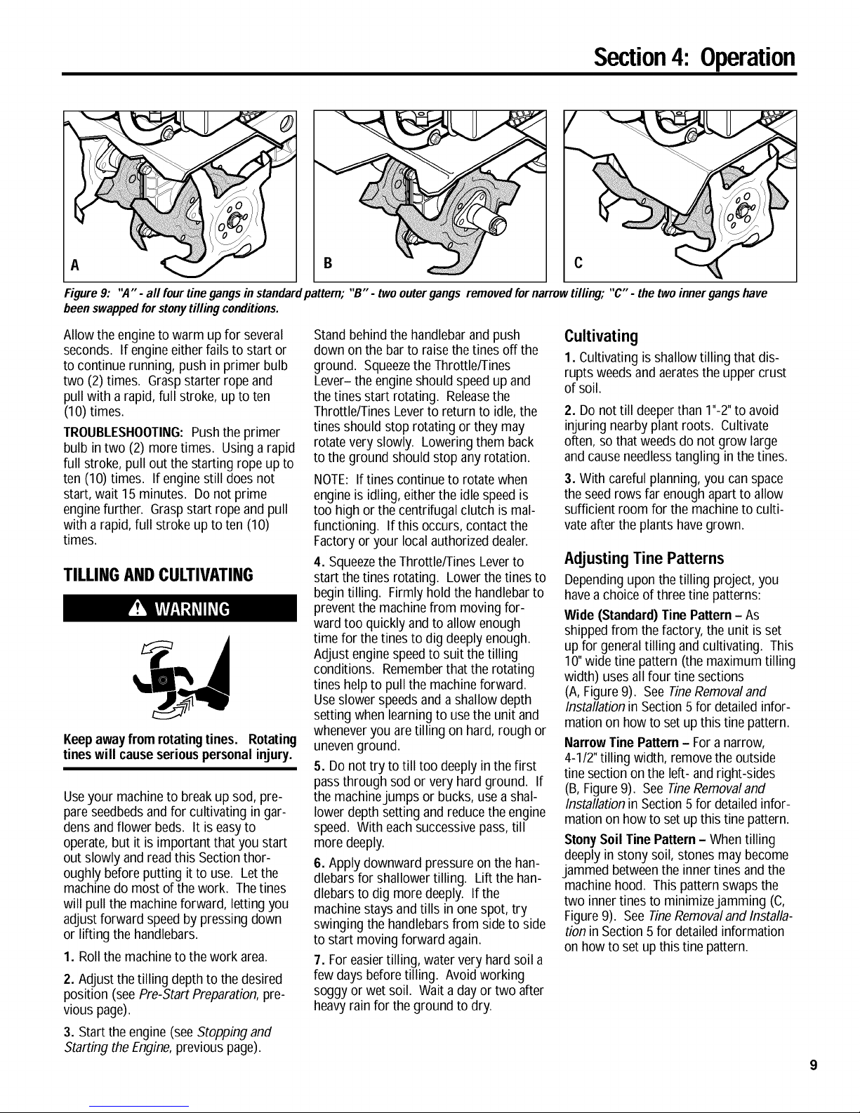
Figure 9: ",4" - all fourtine gangs in standardpattern; "B" - two outergangs removed fornarrow tilling; "C" - the two inner gangshave
beenswappedforstonytilling conditions.
Allow the engineto warm up for several
seconds. If engine eitherfails to start or
to continue running, push in primer bulb
two (2) times. Graspstarter rope and
pull with a rapid, full stroke, up to ten
(10) times.
TROUBLESHOOTING:Pushthe primer
bulb in two (2) more times. Using a rapid
full stroke, pull out the starting rope up to
ten (10) times. If enginestill does not
start, wait 15 minutes. Do not prime
enginefurther. Graspstart rope and pull
with a rapid, full stroke up to ten (10)
times.
TILLINGANDCULTIVATING
Keepawayfrom rotatingtines. Rotating
tineswill causeseriouspersonalinjury.
Useyour machineto breakup sod, pre-
pare seedbedsand for cultivating in gar-
densand flower beds. It is easyto
operate,but it is important that you start
out slowly andreadthis Section thor-
oughly before putting it to use. Letthe
machine do most of thework. Thetines
will pull the machine forward, letting you
adjust forward speed by pressing down
or lifting the handlebars.
1. Roll the machineto the work area.
2. Adjust thetilling depthto the desired
position (see Pre-Start Preparation,pre-
vious page).
3. Start the engine (seeStopping and
Starting the Engine,previous page).
Standbehind the handlebar and push
down on the barto raise the tines off the
ground. Squeezethe Throttle/Tines
Lever- the engineshould speed up and
thetines start rotating. Releasethe
Throttle/Tines Lever to return to idle,the
tines should stop rotating or they may
rotate very slowly. Loweringthem back
to the ground should stop any rotation.
NOTE: If tines continue to rotatewhen
engine is idling, either the idle speedis
too high or thecentrifugal clutch is mal-
functioning. If this occurs, contact the
Factory or your localauthorized dealer.
4. Squeezethe Throttle/Tines Leverto
start the tines rotating. Lowerthe tines to
begin tilling. Firmly hold the handlebarto
prevent the machinefrom moving for-
ward too quickly and to allow enough
time for the tines to dig deeplyenough.
Adjust enginespeedto suit the tilling
conditions. Rememberthat the rotating
tines helpto pullthe machineforward.
Useslower speedsand a shallow depth
setting when learning to usethe unit and
wheneveryou are tilling on hard, rough or
unevenground.
5. Do not try to till too deeply in the first
pass through sod or very hard ground. If
the machinejumps or bucks, usea shal-
lower depth setting and reducethe engine
speed. With eachsuccessive pass,till
more deeply.
6. Apply downward pressure on the han-
dlebarsfor shallower tilling. Liftthe han-
dlebarsto dig more deeply. Ifthe
machine stays and tills in one spot, try
swinging the handlebarsfrom sideto side
to start movingforward again.
7. For easier tilling, water very hard soil a
few days before tilling. Avoidworking
soggy or wet soil. Wait a dayor two after
heavyrain for the ground to dry.
C
Cultivating
1. Cultivating isshallow tilling that dis-
rupts weeds and aeratesthe upper crust
of soil.
2. Do not till deeperthan 1"-2"to avoid
injuring nearbyplant roots. Cultivate
often, so that weeds do not grow large
and cause needlesstangling inthe tines.
3. With careful planning, you canspace
the seedrows far enough apartto allow
sufficient room for the machineto culti-
vate after the plants havegrown.
Adjusting Tine Patterns
Dependingupon the tilling project,you
havea choice of three tine patterns:
Wide (Standard) Tine Pattern- As
shipped from the factory, the unit is set
up for generaltilling and cultivating. This
10"wide tine pattern (the maximum tilling
width) uses all four tine sections
(A,Figure9). SeeTineRemovaland
Installation in Section 5 for detailed infor-
mation on how to set up this tine pattern.
NarrowTine Pattem- Fora narrow,
4-1/2"tilling width, removethe outside
tine sectionon the left- and right-sides
(B,Figure9). See TineRemovaland
Installation in Section 5 for detailed infor-
mation on how to set up this tine pattern.
Stony Soil Tine Pattern - Whentilling
deeply in stony soil, stones may become
jammed betweenthe innertines andthe
machinehood. This pattern swaps the
two innertines to minimizejamming (C,
Figure9). See TineRemovaland Installa-
tion in Section 5 for detailedinformation
on howto set up this tine pattern.
Page 10

Section4: Operation
Tilling Patterns
1. When preparing a seedbed,go over the same pathtwice in
thefirst row, then overlap one-half the machinewidth on each
successivepass (Figure 10).
2. After going up and down the rows in one direction, make
second passesat a right angleacross the original passes
(Figure 11). Again,overlapeachpassto thoroughly pulverize
the entireseedbedarea. In very hardground, it may take three
or four passesbeforethe desireddepth isachieved.
3. If your gardenis not wide enough to till lengthwise andthen
crosswise, then first overlap byone-half the machinewidth,
followed bysuccessive passes at one-quarter machinewidth.
This overlapping method assures thorough tilling.
USINGTHEEDGERATTACHMENT
TheEdgerAttachment makesclean, sharp edgesnext to walkways, driveways,paths, plantedareas,
patios, etc. SeeAssembly Steps,STEP4: in Section 2 for instructions on attaching this attachment.
Takeyour time whenedging. Decidehow far awaythe edge isto befrom the walk or drive, then
slowly proceed using the walk or drive as your sight line.
Otherattachments arecan be purchasedseparately. SeeAttachments below for more details.
Figure10:Useanoverlap
techniqueoneverypass.
Figure 11: Make asecondset
ofpasses at a rightangle over
the first set ofpasses.
ATTACHMENTS
Thefollowing Tiller/Edger attachmentsare availablewhere the Tiller/Edgerwas purchased. Seeyour localauthorized dealeror con-
tactthe Factoryfor details.
Power Lawn Rake Attachment - Model 12575
ThePower LawnRakehelps to keep
your lawn healthy and vigorous.
Mattedgrass anddebris looks
unattractiveand stifles lawn
growth and overall health.
This attachment mounts
without tools andfeatures
dozensof tempered steel
"fingers" that penetrate
and loosen matted grass
without disturbing root
growth. An 18"-wideswath
coversa large lawn areaquickly.
10
Lawn Aerator Attachment - Model 12574
TheLawnAerator Attachmenthelpsto
promote healthy,dense lawns by
loosening andaerating the soil L,
for better root growth. Four
temperedsteel tines punc-
ture the surface of the
lawnthus allowing nutri-
ents to reachthe roots
more easily. Thisattach-
ment assembleswithout
tools.
Page 11
s Maintenance
REQUIREDMAINTENANCE
Beforeinspecting,cleaningor servicing
the machine, shut off engine, let all
movingparts come to a completestop,
disconnectthesparkplugwire and move
thewire away from the sparkplug.
Failure to follow these instructionscan
result in personal injury or property
damage.
Check Tightness of Bolts and Nuts
Clean Engine Cooling System
Check Transmission Lubricant
Service Air Filter
REQUIREDMAINTENANCESCHEDULE
Before After Every Every End
Each Each 25 75 of
Use Use Hours Hours Season
• (1)
• (2)
EQUIPMENTMAINTENANCE
Transmission Maintenance
Thetransmission was lubricated atthe
factory and should not require anyfurther
lubrication.
However,you should checkthe lubricant
levelafter the first five (5) hours of opera-
tion and every twenty-five (25) operating
hours thereafter. If needed,usea high-
quality,automotive-grade petroleum-base
grease.
Before tipping engine or equipment to
service transmission, drain fuel from
tankby runningengine until fuel tank is
empty.
Tocheckthe transmission:
1. Stop the engine, let it cool and discon-
nect the spark plug wire.
2. Placethe machine down on its left side
sothe right end of the tine shaft faces up.
3. Removethe right-side tines (see fine
Removaland Installation in this Section).
4. Cleanthe transmission housing.
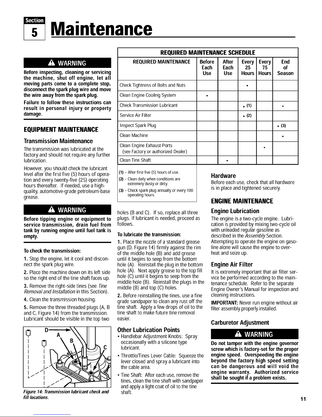
5. Removethe three threaded plugs (A, B
and C,Figure 14) from the transmission.
Lubricant should be visible inthe top two
JJJ:
Figure 14: Transmissionlubricantcheckand
fill locations.
Inspect Spark Plug
Clean Machine
Clean Engine Exhaust Ports
(seeFactory or authorized Dealer)
Clean Tine Shaft
(1) - Afterfirst five (5) hours of use.
(2) - Clean daily when conditions are
extremely dusty or dirty.
(3) - Check spark plug annually or every 100
operating hours.
holes (B and C). If so, replaceall three
plugs. If lubricant is needed,proceedas
follows.
To lubricatethe transmission:
1. Placethe nozzleof a standard grease
gun (D, Figure 14) firmly againstthe rim
of the middle hole (B) and add grease
until it beginsto seepfrom the bottom
hole (A). Reinstallthe plug in the bottom
hole (A). Nextapply greaseto the top fill
hole (C) until it beginsto seepfrom the
middle hole (B). Reinstall the plugs in the
middle (B) andtop (C) holes.
2. Before reinstalling the tines, use a fine
gradesandpaperto clean any rust off the
tine shaft. Applya few drops of oil to the
tine shaft to makefuture tine removal
easier.
Other Lubrication Points
• HandlebarAdjustment Knobs: Spray
occasionally with a silicone type
lubricant.
• Throttle/Tines LeverCable: Squeezethe
leverclosed and spray a lubricant into
the cablearea.
• TineShaft: Aftereachuse,removethe
tines,cleanthetine shaftwith sandpaper
and apply a light coatof oil to thetine
shaft.
• (3)
Hardware
Beforeeachuse,checkthat all hardware
is in placeandtightened securely.
I:Nr.INI: MAINTI:NANrI:
Engine Lubrication
Theengineis a two-cycleengine. Lubri-
cation is provided bymixing two-cycle oil
with unleadedregular gasoline as
described inthe Assembly Section.
Attempting to operatethe engineon gaso-
line alonewill causethe engineto over-
heatandseizeup.
Engine Air Filter
It is extremely important that air filter ser-
vice be performed according to the main-
tenanceschedule. Referto the separate
EngineOwner'sManualfor inspection and
cleaning instructions.
IMPORTANT:Neverrun enginewithout air
filter assemblyproperlyinstalled.
Carburetor Adjustment
Do not tamper with the engine governor
screwwhich isfactory-set for the proper
enginespeed. Overspeedingthe engine
beyond the factory high speed setting
can be dangerous and will void the
engine warranty. Authorized service
shallbe soughtif a problemexists.
11
Page 12

Section5: Maintenance
m' !_r_rl.,lq_ql_qel Beforeinspecting,cleaning orservicingthe machine, shutoff engine, wait for movingpartsto stop, dis-
t _) connectsparkplug wire and movewire awayfromsparkplug.
Failuretofollow these instructionscanresultin seriouspersonalinjuryor propertydamage.
If the engine is running poorly or has low
power whiletilling, an adjustment to the
carburetor may solvethe problem. How-
ever,first inspect and service the spark
plug andthe air filter before making a
carburetor adjustment. Ifthe enginecon-
tinues to run poorly (and the fuel mixture
is fresh), proceedto thefollowing carbu-
retor adjustment instructions.This fac-
tory-engineered instruction is designedto
provide continued optimum engine oper-
ating performance afterthe enginebreak-
in period, which is approximately 5 to 10
hours. Theadjustment, when properly
performed asdescribed below, will not
void the enginewarranty. A common
screwdriver is needed. Ifyou prefer,see
an authorizedengine dealerfor
adjustment.
Prior to CarburetorAdjustment:
Thetemperatureof the muffler and adja-
cent engine areas may exceed 150°F
(65°C). Contact maycauseburns. Avoid
these areas. Remove the spark plug
lead andgroundthelead to the engineto
preventaccidentalstarts andfires.
Failure to dothis could cause personal
injury.
1. Let enginecool for 30 minutes before
continuing.
2. From the operator's position behind the
handlebars, lay the machinedown on its
left side (muffler side).
CarburetorAdjustment:
1. Locatethe carburetor idle mixture
screw (Figure 15). It is directly underthe
air filter and is black.
Do Not AdjustSilver-ColoredScrew.
2. Turn the black idle mixture screw 1/16
of a turn clockwise.
3. Return the unit to its normal upright
operating position and reconnectthe
spark plug wire.
If the enginecontinues to run poorly, con-
tact an authorizedengine dealer.
Spark Plug
Inspectthe spark plug annually or every
100 operating hours according to the
instructions in the separateEngine
Owner's Manual.Checkthat the gap is set
at .030". ForreplacementuseChampion
RCJ-6Yor equivalent (a resistor spark
plug must be usedfor replacement).
Cooling System
It is important to frequently check and
remove grass clippings, dirt and other
debris that accumulateson the engine,
cooling fins, air intakescreen and on
leversand linkages. This helpsto ensure
adequateair cooling and correct engine
speed.
TINE REMOVAL
ANDINSTALLATION
Avoid contactwith the cutting edges on
the tines.
To avoid personal injurywhen removing
or installing tines, wear heavy work
gloves. The engine must be off, all
moving parts stopped, and the spark
plug wire disconnectedfrom the spark
plugand movedaway from the plug.
Thetines will wear with use and they
should be replacediftilling seemsto take
longerthan usualor if the soil is not
being mixed as thoroughly. Also, in addi-
tion to the standard 10"tilling width tine
configuration, the tines canbe arranged
in two other configurations: (1) A narrow,
41/2"tilling width for smaller areasand (2)
A special pattern for stony soil conditions.
Primer Line
-- Idle Speed Screw (Silver)
Idle Mixture Screw (Black)
Figure 16:Remove ring lockpin (,4)to take
off tines.
IMPORTANT:Thering lock pin (A,Figure
16) is under spring tension - wear gloves
to protect your fingers when removing or
replacingthe ring lock pin.
Arranging Tines for Narrow Tilling
1. Propthe machineforward so it rests
on the front of the tubular carrying
handle. The work surface should beflat
andfirm.
2. Flip openthe ring (A, Figure16) on the
left side ring lock pin and remove the ring
lock pin.
3. Removethe outer tine section (do not
remove inner tine section) and mark it as
to which side it is from (left or right) and
whether it's an outer or innertine section.
4. Slideone of the long bushings (B,
Figure17), providedwith the unit, onto
the shaft. Insert the ring lock pin through
the rounded side of the tine shaft and
snapthe ring down over the shaft (see
DETAIL- Ring Lock Pin, Figure4, in
Section 2).
5. Repeatthis procedure on the opposite
side.
Primer Bulb
FuelLine
12 Figure 15: Idle Mixture Screw can be adjusted.
Page 13

Section5: Maintenance
IW!_r_rl.,_:_ll_q_ Beforeinspecting,cleaning orservicingthe machine, shutoff engine, wait for movingpartsto stop, dis-
_, _ connectsparkplugwire and movewire awayfromsparkplug.
Failuretofollow theseinstructionscanresultin seriouspersonalinjuryor propertydamage.
Figure 17: Narrowtilling tine configuration.
ArrangingTines
for Stony Soil Conditions
1. Prop the machineforward so it rests
on the front of the tubular carrying
handle. The work surface should be flat
andfirm.
2. Removethe ring lock pin (A,Figure16)
from both sides of the unit. Removeboth
outer tine sections. Mark each section as
a left or right side tine andwhether it is
an inner or outer section.
Figure 18: Stonysoil tineconfiguration.
3. Removethe innertine sections and
swap their positions (the inner right-side
section goesonto the left side of the
machine,and the inner left-sidegoes onto
the right side of the machine).
4. Reinstall the two outer tine sections on
the sidesfrom which they wereremoved
(Figure 18).
5. Insert the ring lock pins through the
rounded side of thetine shaftsand snap
the rings down over the shafts (see
DETAIL- Ring Lock Pin, Figure 4,
Section2).
ToReplaceWorn TineSections:
Thetines are excessivelyworn if tilling
takes much longer than beforeand the
soil is not being mixed thoroughly
enough.
1. Prop the machineforward so it rests
on the front of the tubular carrying
handle. The work surface should be flat
and firm.
2. Removethe ring lock pin (A, Figure 16)
from both sides of the unit. Removethe
old tine sections and replacethem with
newtine sections. Referto Figure16 and
the tine patternshown in the Parts List
for tine positioning details. Insert the ring
lock pinsthrough the rounded side of the
tine shafts and snapthe ring over the
shaft (seeDETAIL- RingLock Pin,Figure
4, in Section 2).
• Never store your equipment when
there is fuel mixturein the fuel tank.
• Never place your equipmentnear any
sourceof sparksor open flame (such
as from a hot water heater, a space
heateror clothesdryer).
Failure to comply can result in serious
personalinjury or propertydamage.
STORAGE
IMPORTANT:It is important to prevent
gum depositsfrom forming in essential
fuel system parts such ascarburetor,fuel
filter, fuel hose, or tank during storage.
Also, experienceindicatesthat alcohol-
blendedfuels (calledgasoholor using
ethanolor methanol)can attract moisture
which leadsto separationand formation
of acids during storage. Acidic gas can
damagethe fuel system of an enginewhile
in storage.
Off-SeasonStorageProcedure
1. Drain the fuel tank of all of the gaso-
line/two-cycle oil mixture. NOTE:Donot
usea fuel mixture that isolder than one
season in order to avoid varnish deposits
throughout the fuel system. Dispose of
thefuel mixture properly.
2. Start engine and run until fuel mixture
is used up. This will prevent poor perfor-
mancefrom stalefuel when your equip-
ment istaken out of storage.
NOTE: If"Gasohol" has beenused, com-
pleteabove instructions and then put 1/2
pint of gasolineproperly mixed with two-
cycleoil (seeFuelMixing Chart) into fuel
tank and repeataboveinstructions.
NOTE: Fuelstabilizer (such as STA-BIL)
is an acceptablealternative in minimizing
theformation of fuel gum deposits during
storage. Add stabilizerto the fuel mixture
in the fuel tank or the fuel storage con-
tainer. Alwaysfollow the mix ratio
instructions on the stabilizer container.
Runengine at least 10 minutes after
adding stabilizer to allowthe stabilizer to
reachthe carburetor. Donot drain the
gastank and carburetor if using fuel
stabilizer.
3. Let engine cool down after fuel mixture
hasbeen used up. Cleandirt and debris
from engine cooling fins, linkage and
other enginesurfaces.
4. Pull starter handle slowly until resis-
tance is felt due to compression pressure,
thenstop. Releasestarter tension slowly
to prevent enginefrom reversing due to
compression pressure.This position will
close both the intake andexhaustports to
prevent corrosion of the piston and
cylinder bore.
5. Removetines. Cleanall soil anddebris
from dust coversand tine shaft. Lubri-
catetine shaft with light oil. Replace
tines.
6. Coverengineand store equipment in a
dry, sheltered location.
13
Page 14

Section5: Maintenance
!_W._N:_1 hq_
Beforeinspecting,cleaning orservicingthe machine, shutoff engine, wait for movingpartstostop, dis-
connectsparkplugwire and movewire awayfrom sparkplug.
Failuretofollow these instructionscanresultin seriouspersonalinjuryor propertydamage.
TROUBLESHOOTING
Beforeperforming any of the corrections in this TroubleshootingChart, refer to the appropriate information contained in this Manual
andthe EngineOwner'sManualfor thecorrect safetyprecautionsand servicing procedures. Contactyour local authorized Engine
Service Dealerfor engine service. Contact your local authorized dealerfor service problems with the machine.
Engine doesnot start. 1. Reconnect
Engine runs poorly or
has low power under
tilling conditions.
Engine overheats. 1. Engine cooling fins clogged. 1. Remove dirt and debris from fins.
I. Spark plug wire disconnected.
2. Out of gas/two-cycle oil fuel mixture.
3. Stale fuel mixture.
4. Priming procedure not correct.
5. Dirty air filter(s).
6. Worn, corroded or broken spark plug.
7. On/Off Switch in OFF position.
1. Fouled spark plug.
2. Dirty air filter(s).
3. Stale fuel mixture.
4. Carburetor out of adjustment.
2. Improper amount of oil in fuel mixture. 2. Drain tank; fill with correct mixture.
re to sparkplug.
2. Check fuel tank. Add fuel mixture.
3. Drain old mixture. Add fresh mixture.
4. Refer to starting procedure in manual.
5. Clean or replace air filters.
6. Replace spark plug.
7. Move On/Off Switch to ON.
1. Remove, inspect, clean spark plug.
2. Clean or replace dirty air filters.
3. Drain old mixture. Add fresh mixture.
4. Adjust carburetor. See Manual.
Tines stop rotating. 1. Object wedged between tines and hood. 1. Remove wedged object.
2. Internal transmission problem. 2. Authorized service dealer.
SAFETY AND OPERATING DECALS
Decalsare not shown at full size. SeeParts List pagesfor reordering information.
Ontopof handlebar
Onrear, left-side
tine shield
Ontop, left-side tine
shield
Onright-side handlebar
14
Onrear,right-sidetine
shield
Page 15

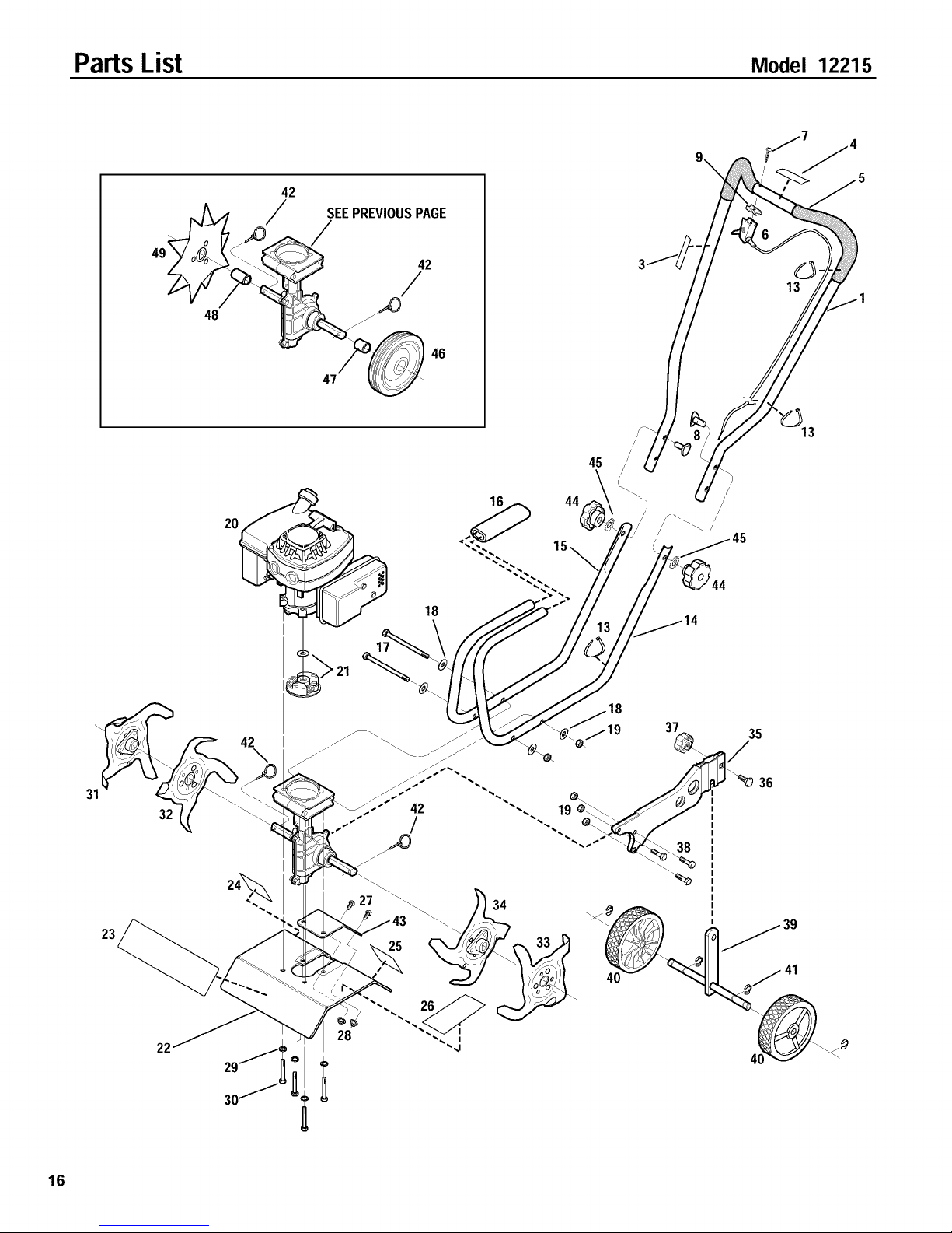
PartsList Model 12215
B
Ref# Part#
1 1915039
1915040
3
1983632
4
1918307
5
1983731
6
1983636
7
1983637
8
1904416
9 1909923
10 1185741
11 1111600
10
A
B
,/
14, 15
16,
TRANSMISSIONASSEMBLY
Description Qty.
Transmission Case- left-side.
(Incl. pressed-on bushing) ............. 1
Transmission Case- right-side.
(Incl. pressed-on bushing) ............. 1
Oil Seal .............................. 2
Worm Input Shaft Assembly ............. 1
Input Bearing ......................... 2
Thrust Bearing ........................ 1
BallBearing .......................... 1
Shaft Assembly. (Incl. pressed-on worm
gear and two ring lockpins) ............ 1
Input Oil Seal ......................... 1
Plug, 1/8 ............................ 3
HexScrew, 1/4-20 x 7/8 (five locations,
identified as"A" on transmission case) .... 5
14, 15
Ref# Part#
12 1100069
13 1817146
14 1983635
15 1983640
16 1983641
17 1983642
18 1983638
19 1107381
20 1983663
21 1909486
22 1747166
23 1915055
24 1983713
20
22
23
11, 12
22
Description Qty.
HexScrew, 1/4-20 x 1 (three locations,
identified as"B" on transmission case) .... 3
Locknut, Nyloc, 1/4-20 .................. 8
Thrust Washer,Output (.050") ............ AIR
Thrust Washer,Output (.040") ............ AIR
Thrust Washer, Input (.020") ............. AIR
Thrust Washer, Input (.035") ............. AIR
Thrust Washer ........................ 2
FlatWasher,1/4 ....................... 2
HexHal.Screw, 1/4-20 x 5 ............... 2
Clutch Drum and Hub .................. 1
Set Screw, 1/4-28 x 3/8 ................. 4
DustCover ........................... 2
FeltWasher .......................... 2
A/R - As Required
15
Page 16
PartsList Model 12215
9 _/7 /45
42
SEEPREVIOUSPAGE
48
45
31
32
23
30/
16
28
Page 17
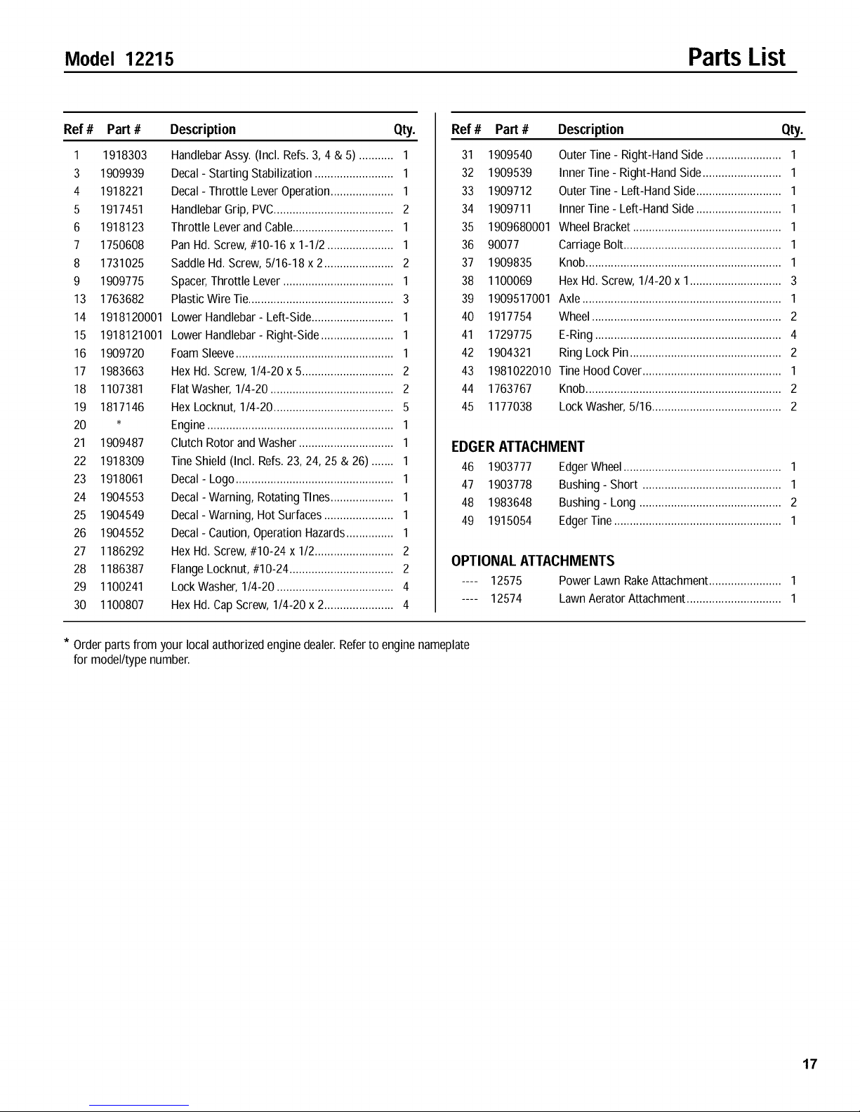
Model 12215 PartsList
Ref# Part#
1 19183O3
3 19O9939
4 1918221
5 1917451
6 1918123
7 1750608
8 1731025
9 1909775
13 1763682
14 1918120001
15 1918121001
16 1909720
17 1983663
18 1107381
19 1817146
20
21 1909487
22 1918309
23 1918061
24 1904553
25 1904549
26 1904552
27 1186292
28 1186387
29 1100241
30 1100807
Description Qty.
HandlebarAssy. (Incl. Refs.3, 4 & 5) ........... 1
Decal- Starting Stabilization ......................... 1
Decal- Throttle LeverOperation.................... 1
HandlebarGrip, PVC...................................... 2
Throttle Leverand Cable................................ 1
Pan Hd. Screw, #10-16 x 1-1/2 ..................... 1
Saddle Hd. Screw, 5/16-18 x 2 ...................... 2
Spacer,Throttle Lever ................................... 1
PlasticWire Tie.............................................. 3
Lower Handlebar- Left-Side.......................... 1
Lower Handlebar- Right-Side....................... 1
FoamSleeve.................................................. 1
Hex Hd. Screw, 1/4-20 x 5............................. 2
FlatWasher,1/4-20 ....................................... 2
Hex Locknut, 1/4-20...................................... 5
Engine........................................................... 1
Clutch Rotor and Washer .............................. 1
TineShield (Incl. Refs.23, 24, 25 & 26)....... 1
Decal- Logo.................................................. 1
Decal-Warning, Rotating Tines.................... 1
Decal- Warning, Hot Surfaces...................... 1
Decal- Caution, Operation Hazards............... 1
Hex Hd. Screw, #10-24 x 1/2......................... 2
FlangeLocknut, #10-24................................. 2
LockWasher, 1/4-20 ..................................... 4
Hex Hd. CapScrew, 1/4-20 x 2...................... 4
Ref# Part #
31 1909540
32 1909539
33 1909712
34 1909711
35 1909680001
36 90077
37 1909835
38 1100069
39 1909517001
40 1917754
41 1729775
42 1904321
43 1981022010
44 1763767
45 1177038
Description Qty.
Outer Tine - Right-HandSide ........................ 1
Inner Tine - Right-HandSide......................... 1
Outer Tine - Left-Hand Side........................... 1
Inner Tine - Left-Hand Side ........................... 1
Wheel Bracket............................................... 1
CarriageBolt .................................................. 1
Knob.............................................................. 1
Hex Hd. Screw, 1/4-20 x 1............................. 3
Axle............................................................... 1
Wheel............................................................ 2
E-Ring........................................................... 4
RingLock Pin................................................ 2
Tine Hood Cover............................................ 1
Knob.............................................................. 2
LockWasher, 5/16......................................... 2
EDGERATTACHMENT
46 1903777 EdgerWheel .................................................. 1
47 1903778 Bushing- Short ............................................ 1
48 1983648 Bushing- Long ............................................. 2
49 1915054 EdgerTine ..................................................... 1
OPTIONAL ATTACHMENTS
.... 12575 Power Lawn RakeAttachment....................... 1
.... 12574 Lawn Aerator Attachment .............................. 1
* Orderparts from your local authorized engine dealer.Referto engine nameplate
for model/typenumber.
17
Page 18

Notes
18
Page 19

Index
AccessoriesandAttachments ....................... 14
AeratorAttachment ............................... 14
Air Filter ....................................... 11
Assembly ....................................... 5
Borders......................................... 5
Border/EdgerAttachment ...................... 5, 6, 10
Carburetor.................................... 7, 12
Control Lever,Throttle/Tines ................ 3, 4, 6, 9, 11
Cultivating .................................... 9, 10
Decals .......................................... 2
Edging....................................... 5, 14
Engine
Air Filter ..................................... 11
Carburetor ................................. 7, 12
Cleaning .................................. 11, 13
FuelMixture ........................... 5, 6, 12, 13
FuelPrimer Bulb ...................... 4, 8,9, 12, 14
On/OffSwitch ........................... 4, 5, 7, 8,
Operation ..................................... 8
Recoil Start Rope ............................... 8
Spark Plug ............................. 11, 12, 14
Speed ................................... 7, 9, 12
Starting Engine................................. 8
Stopping Engine ................................ 8
Storage................................ 4, 5, 8, 13
Throttle/Tines Lever .................... 3, 4, 5, 9, 11
Features/Controls................................. 7
FuelMixture ............................. 5, 6, 12, 13
FuelPrimer Bulb ........................ 4,8,9, 12, 14
Gasoline/Two-CycleOil ..................... 5, 6, 12, 13
HandlebarHeight Adjustment ...................... 7, 8
Hardware ........................................ 5
Lubrication ..................................... 11
Maintenance.................................... 11
Model/Serial Number ....................... BackCover
Oil/GasolineMixture ....................... 5, 6, 12, 13
Off-SeasonStorage ............................... 11
Operation ....................................... 8
PartsList .................................... 15-17
Power LawnRake ................................ 10
Preparation .................................... 3, 8
RecoilStarter Rope ............................... 98
RepairParts .................................. 15-17
SafetyRules .................................... 3-4
SafetyDecals .................................... 2
Service RecommendationChecklist .................. 11
SparkPlug ............................... 11, 12, 14
Starter Rope ..................................... 8
Storage .................................. 4, 5, 8, 13
Tilling ....................................... 9, 10
Tilling Depth Adjustment ............................ 9
Tilling Widths .................................... 9
TineRemoval ................................... 12
Tips/Techniques ............................... 9, 10
Troubleshooting ............................... 9, 14
Unpacking ....................................... 5
W,X, V,Z
19
Page 20
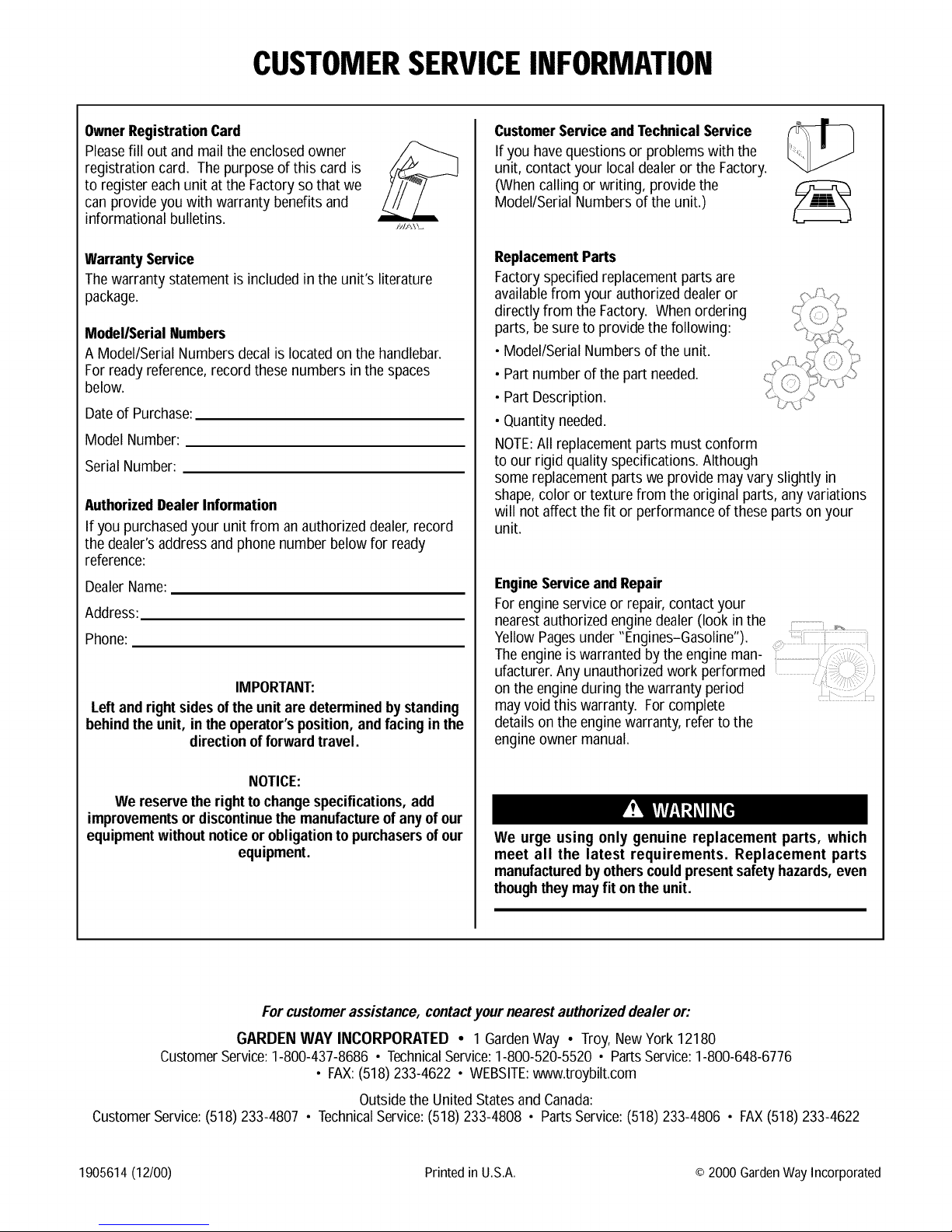
CUSTOMERSERVICEINFORMATION
OwnerRegistrationCard
Pleasefill out and mailthe enclosed owner
registration card. The purposeof this card is
to register eachunit at the Factoryso that we
can provideyou with warranty benefits and
informational bulletins.
WarrantyService
Thewarranty statement is included in the unit's literature
package.
Model/Serial Numbers
A Model/Serial Numbers decal is locatedon the handlebar.
For readyreference,recordthese numbers in the spaces
below.
Dateof Purchase:
Model Number:
Serial Number:
AuthorizedDealerInformation
If you purchasedyour unit from an authorizeddealer,record
the dealer's addressand phone number below for ready
reference:
DealerName:
Address:
Phone:
IMPORTANT:
Leftand rightsidesof the unitare determined by standing
behindthe unit, in theoperator'sposition, andfacingin the
directionofforwardtravel.
CustomerServiceandTechnicalService
If you havequestions or problems with the
unit, contact your localdealer or the Factory.
(Whencalling or writing, providethe
Model/Serial Numbers of the unit.)
ReplacementParts
Factoryspecified replacement parts are
availablefrom your authorizeddealer or
directly from the Factory. Whenordering
parts, besure to provide the following:
• Model/Serial Numbersof the unit.
• Part number of the part needed.
• Part Description.
• Quantity needed.
NOTE:All replacementparts must conform
to our rigid quality specifications.Although
some replacement parts we provide may vary slightly in
shape,color or texture from the original parts, any variations
will not affect the fit or performance of these parts on your
unit.
EngineServiceand Repair
Forengineservice or repair, contact your
nearestauthorized enginedealer (look in the
YellowPagesunder "Engines-Gasoline").
Theengine is warranted by the engine man-
ufacturer.Any unauthorized work performed
on the engineduring the warranty period
may void this warranty. For complete
details on the enginewarranty, refer to the
engineowner manual.
NOTICE:
We reservethe rightto changespecifications,add
improvementsordiscontinuethe manufactureofanyof our
equipmentwithout noticeor obligationtopurchasersofour
equipment.
Forcustomerassistance,contactyour nearestauthorizeddealer or:
GARDENWAY INCORPORATED • 1 GardenWay • Troy, NewYork12180
CustomerService:1-800-437-8686 • TechnicalService:1-800-520-5520 • PartsService:1-800-648-6776
• FAX:(518) 233-4622 • WEBSITE:www.troybilt.com
CustomerService:(518) 233-4807 • TechnicalService:(518) 233-4808 • PartsService:(518) 233-4806 • FAX(518)233-4622
1905614 (12/00) Printed in U.S.A. © 2000 Garden Way Incorporated
We urge using only genuine replacement parts, which
meet all the latest requirements. Replacement parts
manufacturedbyotherscouldpresentsafetyhazards,even
thoughthey mayfit onthe unit.
Outsidethe United Statesand Canada:
 Loading...