

GARDEN WAY
_ TRD_J_!LT"
Model
12213- 4.5HP
GARDEN WAYINCORPORATED
Owner'sManual
REAR-TINETILLER
• Safety
• Assembly
• Controls
• Operation
• Maintenance
• Parts List

DearOwner:
You now own one of the finest standard-rotating-tine tillers
available.Your new tiJJerallows you to tiJland cultivateyour
gardenwith ease,andaccomplish dozensof other property
managementprojects aswell. Your tiller is famous for its
ruggedness,performance and high-quality engineering. We
know you'll enjoyusing it.
Pleasecarefully readthis Manual. Ittells you howto safely
and easily assemble, operateand maintain your machine.
Besure that you and anyother operators carefully follow
the recommended safety practices atall times. Failureto
do so could result in personal injury or property damage.
Of course, if you should ever haveany problems or
questions, pleasecontact your local authorized dealeror
call the Factory (seehack cover of this Manual). We want to
be sore that you are completely satisfied at arttimes.
NOTE:Be sure to fill out and return the Warranty Registra-
tion Cardthat was supplied with this Manual.
See Back Cover for
Customer Service Information
Safety AlertSymbol
,_ This isa safety alert symbol. It is used in this
manualand on the unit to alertyou to
potential hazards. When you see this symbol,
readand obeythe messagethat follows it.
Failureto obeysafety messagescould result in personal
injury or property damage.
This machine meets voluntary safety standard B71.8
- 1996, which is sponsored by the Outdoor Power
Equipment Institute, Inc., and is published by the
American National Standards Institute.
WARNING
The engine exhaust from this product contains
chemicals known te the State of California to cause
cancer, birth defects or other reproductive harm.
2
Tableof Contents
SECTION1: SAFETY........................................... 3
SafetyDecals .................................................................... 5
SECTION2: ASSEMBLY....................................... 6
Attach Handlebar............................................................... 7
Move Tiller Off Shipping Platform ...................................... 7
Install Forward Clutch Cable.............................................. 8
CheckLevel ofTransmission GearOil................................ 9
Add Motor Oil to Engine..................................................... 9
CheckHardwarefor Tightness........................................... 9
CheckAir Pressure in Tires................................................ 9
SECTION3: FEATURES& CONTROLS........................ 10
Wheel Drive Pins ............................................................... 10
Forward ClutchBail............................................................ 11
Depth Regulator................................................................. 11
HandlebarHeightAdjustment ............................................ 11
SECTION4: OPERATION...................................... 12
Break-in Operation.......................................................... 12
Starting and Stoppingthe Engine...................................... 12
Operatingthe Tifler ............................................................ 13
Tilling Tips & Techniques .................................................. 15
PowerComposting ............................................................ 17
Loadingand Unloading the Tiller ....................................... 17
SECTION5: MAINTENANCE.................................. 18
RequiredMaintenance Schedule........................................ 18
Tiller Lubdcation................................................................ 19
Checkfor Oil Leaks............................................................ 19
CheckHardware................................................................. 19
CheckTire Pressure........................................................... 19
Transmission GearOil Service........................................... 19
Bold Tines.......................................................................... 20
Checkingand Adjusting Forward Drive Belt Tension.......... 21
Forward ClutchBailAdjustment ......................................... 21
EngineCleaning................................................................. 22
Air CleanerService............................................................ 22
EngineOil Service.............................................................. 22
Spark Plug Service............................................................ 22
SparkArrestor Screen Service........................................... 22
CarburetodGovernor Control Adjustments ........................ 22
Off SeasonStorage............................................................ 22
Troubleshooting................................................................. 23
PARTSLIST ..................................................... 24
CUSTOMERSERVICEINFORMATION.............. BackCover
I1
Safety
SPARKARRESTERWARNINGTO RESIDENTSOFCALIFORNIA ANDSEVERAL OTHERSTATES
UnderCalifornialaw, and under the laws of severalother states, you are not permitted to operate an
internalcombustion engine using hydrocarbon fuels on any forest, brush, hay, grain, or grass
covered land; or land covered by anyflammable agricultural crop without anengine spark arrester in
continuous effective working order.
Theengine on the unit is an internal combustion engine which burns gasoline, a hydrocarbon fuel, and must be equipped with a
spark arrester muffler in continuous effectiveworking order. The spark arrester must beattached to the engine exhaustsystem in
such a mannerthat flames or heatfrom the system will not ignite flammable material. Failureof the owner/operator of the unit to
comply with this regulation is a misdemeanor under California law (and other states) and may alsobe a violation of other state
and/or federal regulations, laws, ordinances or codes. Contactyour local fire marshal or forest servicefor specific information
about which regulations apply in your area.
Training
1. Carefully readthis
Owner'sManual, the
separateEngineOwner's
Manual,and any other literature you may
receive.Bethoroughly familiar with the
controls and the proper useof the tiller
and its engine,Know how to stop the unit
and disengagethe controls quickly.
2. Neverallow children to operatethe
tiller. Neverallow adults to operatethe
tiller without proper instruction.
3. Keepthe area of operation clearof all
persons,particularly children and pets.
4. Keepin mind that the operator or user
isresponsible for accidents or hazards
occurring to other people,their property,
andthemselves.
Preparation
1. Thoroughly inspect the areawhere the
tiller is to be used and remove all foreign
objects.
2. Be sure all tiller controls arereleased
and both wheels are in the Wheel Drive
position before starting the engine.
3. Do not operate the tiller without
wearingadequate outer garments, Avoid
loose garments or jewelry that could get
caught in moving parts.
4. Do not operate the tiller when barefoot
or wearing sandals, sneakers,or light
footwear. Wear protective footwear that
will improve footing on slippery surfaces,
5. Do nottill nearunderground electric
cables, telephone lines, pipes or hoses. If
in doubt, contact your telephone or utility
company.
6. Warning: Handlefuel with care; it is
highly flammable and its vapors are
explosive. Besure to take the following
precautions:
a. Storefuel in containers specifically
designedfor this purpose.
b. The gas cap shall never be removed
or fuel added while the engine is
running. Allow the engine to cool
for several minutes beforeadding
fuel.
c. Keepmatches, cigarettes, cigars,
pipes, openflames, and sparks
away from the fuel tank and fuel
container.
d. Fillfuel tank outdoors with extreme
care.Neverfill fuel tank indoors.
Usea funnel or spout to prevent
spillage.
e. Replaceall fuel tank and container
caps securely.
f. Iffuel is spilled, do not attempt to
start the engine, but move the
machine awayfrom the area of
spillageand avoid creating any
source of ignition until fuel vapors
havedissipated.
7. Nevermake adjustments when engine
is running (unless recommended by
manufacturer).
Operation
1. Do not put handsor feet near or under
rotating parts.
2. Exerciseextreme caution when on or
crossing gravel drives, walks, or roads.
Stay alertfor hidden hazardsor traffic. Do
not carry passengers.
3, After striking a foreign object, stop the
engine, removethe wire from the spark
plug wire and prevent it from touching
the spark plug. Thoroughly inspectthe
machinefor any damageand repairthe
damagebefore restarting and operating
the machine.
4. Exercisecaution to avoid slipping or
falling.
5. If the unit should start to vibrate abnor-
mally,stop the engine, disconnect the
spark plug wire and prevent it from
touching the spark plug, and check
immediately for the cause.Vibration is
generallya warning of trouble.
6. Stop the engine, disconnect the spark
plug wire and prevent it from touching
the spark plug whenever you leavethe
operating position, beforeunclogging the
tines, or when making any repairs, adjust-
ments or inspections.
Section1: Safety
7. Take all possible precautions when
leavingthe machine unattended.Stop the
engine. Disconnectspark plugwire and
move it awayfrom the spark plug. Be
sure both wheels are in the Wheel Drive
position.
8. Before cleaning, repairing, or inspect-
ing, stop the engineand make certain all
moving parts havestopped. Disconnect
the spark plug wire and prevent it from
touching the spark plug to prevent acci-
dental starting.
9. The flap on the tine hood must be
down when operating the tiller.
10. Never usethe tiller unless proper
guards, plates,or other safety protective
devicesare in place.
11. Do not run engine in an enclosed
area. Engineexhaust contains carbon
monoxide gas, a deadlypoison that is
odorless, colorless, and tasteless.
12. Keepchildren and pets away.
13. Never operatethe tiller under
engine powerif the wheels are in the
Freewheel position.In the Freewheel
position, the wheels will not hold the tiller
back and the revolving tines could propel
the tiller rapidly, possibly causing loss of
control. Always engagethe wheels with
the wheel drive pins in theWheel Drive
position beforestarting the engine or
engaging the tines/wheels with the
Forward Clutch Bail.
14. Be aware that the tiller may unex-
pectedlybounceupwardor jump
forwardif the tines shouldstrike
extremely hardpackedsoil, frozen
ground,or buried obstacleslike large
stones,roots, or stomps. If in doubt
aboutthe tilling conditions,alwaysuse
the following operatingprecautionsto
assistyouin maintaining controlof the
tiller:
a. Walk behindand to oneside ol the
tiller, usingone hand onthe han-
dlebars. Relaxyour arm, butusea
securehandgrip.
b. Use shallowerdepth regulator
settings,workinggradually
deeperwith each pass.
c. Useslower enginespeeds.
d. Clear thetilling area ofall large
stones,rootsand otherdebris.
e. Avoidusingdownwardpressure
on handlebars.If need be, use
slight upwardpressureto keep the
tines lrom diggingtoodeeply.
f. Beforecontactinghardpackedsoil
atthe end of a row, reduceengine
speedand lift handlebarsto raise
tines outofthe soil.
go In an emergency, stoptines and
wheels byreleasing whichever
clutchcontrol isengaged. Donot
attemptto restrainthetiller.
15. Do not overload the tiger's capacity
by attempting to till too deeplyat too fast
a rate.
16. Never operate thetiller at high
transport speeds on hard or slippery
surfaces. Look behind and usecare when
backing up.
17. Do not operate the tiller on a slope
that is too steepfor safety. When on
slopes, slow down and makesure you
havegood footing. Neverpermit the tiller
to freewheel down slopes.
18. Never allow bystanders nearthe unit.
19. Only useattachments and acces-
sories that are approvedby the manufac-
turer of the tiller.
20. Usetiller attachments and acces-
sories when recommended.
21. Neveroperate the tiller without good
visibility or lighL
22. Neveroperate the tiller ifyou are
tired, or under the influence of alcohol,
drugs or medication.
23. Operatorsshall not tamper with the
engine-governor settings on the machine;
the governor controls the maximum safe
operating speed to protect the engineand
all moving parts from damagecausedby
overspeed. Authorized service shall be
sought if a problem exists.
24. Do not touch engine partswhich may
behot from operation, Let parts cool
down sufficiently,
25. Pleaseremember: You can always
stop the tines and wheels by releasingthe
Forward Clutch Bail or by moving the
Throttle Control Lever on theengine to
"OFF"or "STOP".
26. To load or unload the tiller, see the
instructions in Section 4 of this Manual.
27. Use extreme caution when reversing
or pulling the machine towards you.
28. Start the engine carefully according to
instructions and with feet well away from
thetines.
29. Neverpick upor carry amachine
while the engine is running.
Maintenance and Storage
1. Keepthe tiller, attachments and acces-
sories in safe working condition.
2. Checkall nuts, bolts, and screws at
frequent intervals for proper tightness to
besure the equipment is in safeworking
condition.
3. Neverstore the tiller with fuel in the
fuel tank inside a building where ignition
sources are present such as hot water
and spaceheaters,furnaces, clothes
dryers, stoves, electric motors, etc.).
Allow engineto cool before storing in any
enclosure.
4. To reducethe chances of afire hazard,
keepthe engine free ofgrass, leaves,or
excessivegrease.
5. Store gasolinein a cool, welI-ventilated
area,safely away from anyspark- or
flame-producing equipment. Store
gasoline in an approved container, safely
awayfrom the reach of children.
6. Referto the Maintenance sections of
this Manual and the separateEngine
Owner's Manual for instructions if the
tiller is to be stored for an extended
period.
7. Neverperform maintenancewhile the
engine is running or the spark plug wire
is connected, except when specifically
instructed to do so.
8. If the fuel tank has to be drained, do
this outdoors,
Section1: Safety
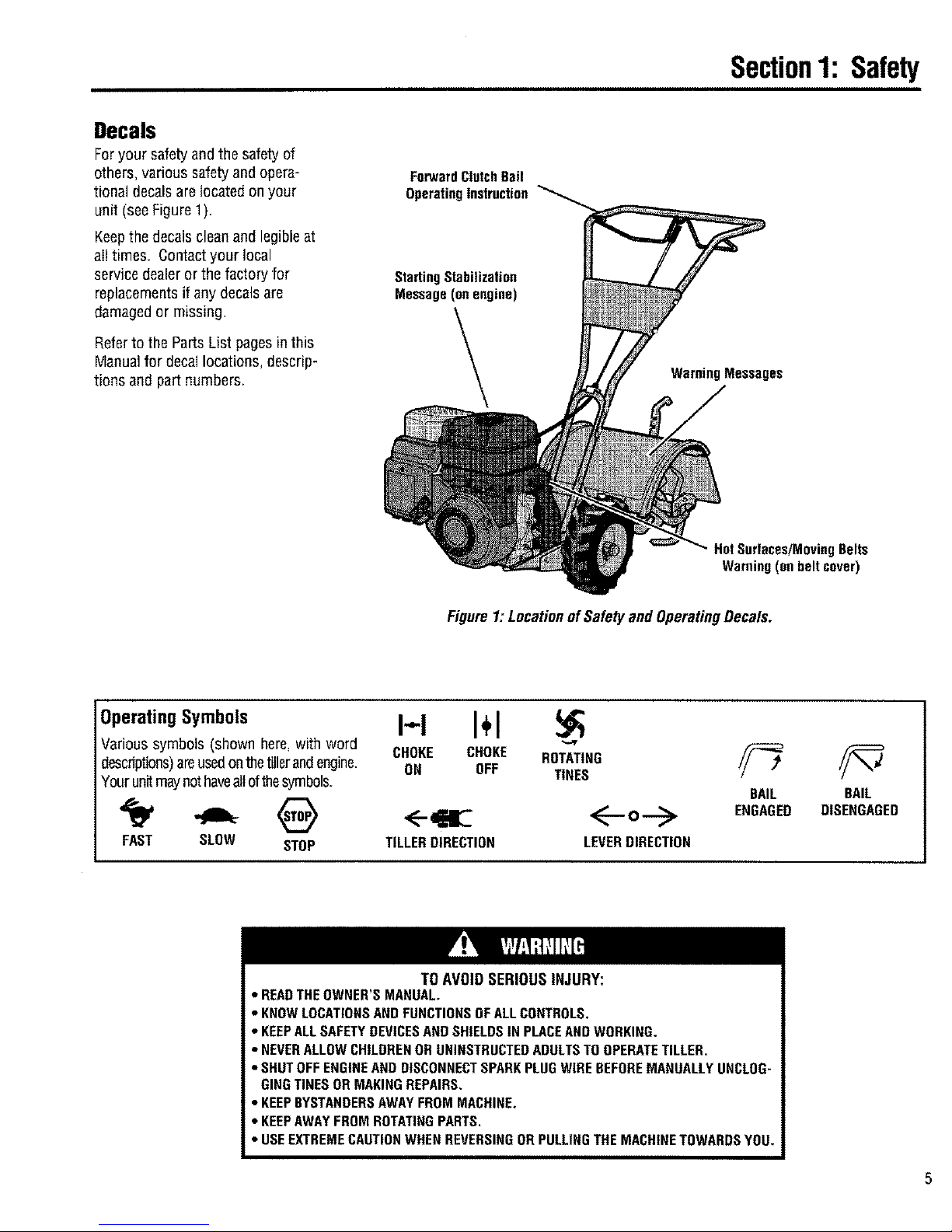
Decals
Foryour safety and the safety of
others, various safetyand opera-
tional decalsare located on your
unit (see Figure 1).
Keepthe decals clean and legible at
al!times. Contactyour local
service dealer or the factory for
replacementsif any decalsare
damaged or missing.
Referto the Parts List pagesin this
Manualfor decallocations, descrip-
tions and part numbers.
ForwardClutchBail
OperatingInstruction
Starting Stabilization
Message(on engine)
WarningMessages
HotSurfaces/MovingBelts
Warning(onbeltcover)
Figure1: LocationofSafetyand OperatingDecals.
OperatingSymbols
Various symbols (shown here, with word
desndptions)areused onthe tiller and engine.
Your unit may not haveall of the symbols.
FAST SLOW STOP
I-,,-I I+1
CHOKE CHOKE ROTATING
ON OFF TINES
TILLERDIRECTION LEVERDIRECTION
BAIL
ENGAGED
BAIL
DISENGAGED
TO AVOID SERIOUS INJURY:
• READTHEOWNER'S MANUAL,
• KNOWLOCATIONSANDFUNCTIONSOFALLCONTROLS.
• KEEPALLSAFETYDEVICESAND SHIELDSIN PLACEANDWORKING.
• NEVERALLOWCHILDRENOR UNINSTRUCTEDADULTSTOOPERATETILLER.
• SHUTOFFENGINEANDDISCONNECTSPARKPLUGWIRE BEFOREMANUALLYUNCLOG-
GINGTINES OR MAKINGREPAIRS.
• KEEPBYSTANDERSAWAYFROMMACHINE,
• KEEPAWAYFROMROTATINGPARTS,
• USEEXTREMECAUTIONWHENREVERSINGORPULLINGTHE MACHINETOWARDSYOU.
I1
Assembly
To preventpersonal injury or property
damage, do net start fhe engine until
all assembly steps are complete and
you have read and understand the
safety and operatinginstructionsinthis
manual.
Introduction
Carefullyfollow these assembly steps to
correctly prepareyour tiller for use. It is
recommendedthat you readthis Section
in its entirety before beginning assembly.
Inspectunit
Inspect the unit and carton for damage
immediately after delivery. Contactthe
carrier (trucking company) if you find or
suspect damage. Inform them of the
damageand request instructions for filing
a claim. To protect your rights, put your
claim in writing and mail acopy to the
carrier within 15 days after the unit has
been delivered.Contact us at the factory if
you needassistance in this matter.
STEP1: UnpackingInstructions
NOTE:Becareful not to severely bend any
of the control cableson the unit.
1. Removeanycardboard inserts and
packagingmaterial from the carton.
Removeany staples from the bottom of
the carton and remove the carton.
2. The tiller is heavy (approximately 133
]bs.). Oonot attempt to remove it from
the shipping platform until instructed to
do so in these Assembly steps.
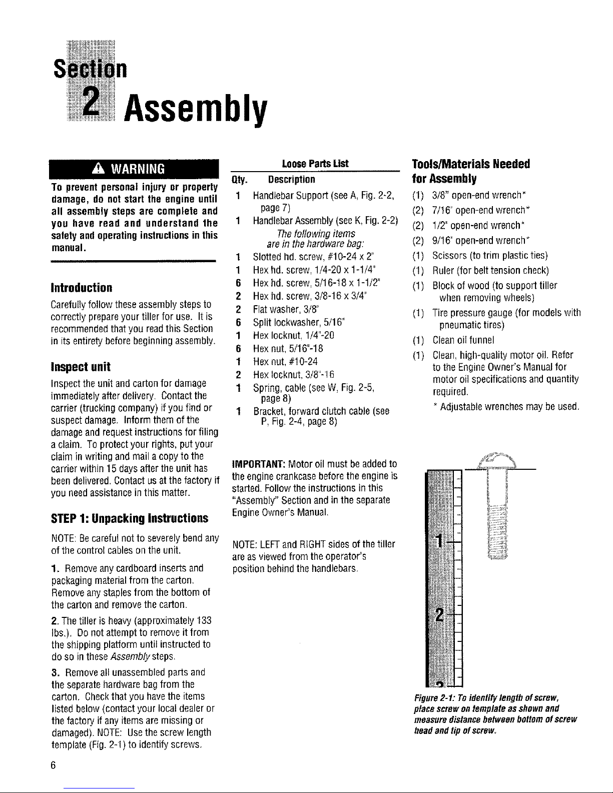
3. Removeall unassembledparts and
the separatehardware bagfrom the
carton, Checkthat you havethe items
listed below(contact your local dealeror
the factory if anyitems are missing or
damaged). NOTE: Usethe screw length
template (Fig. 2-1) to identify screws.
LooseParts List
Qty. Description
1 HandlebarSupport (seeA, Fig. 2-2,
page 7)
1 HandlebarAssembly(see K,Fig.2-2)
Thefollowing items
are in the hardware bag:
1 Slotted hd. screw, #10-24 x 2"
1 Hexhd. screw, 1/4-20 x 1-1/4"
6 Hexhd. screw, 5/16-t8 x 1-1/2"
2 Hexhd screw, 3/8-16 x 3/4"
2 Flatwasher,3/8"
6 Split Iockwasher,5/16"
1 Hex Iocknut, 1/4'-20
6 Hex nut, 5/16"-18
1 Hex nut,#10-24
2 Hexlocknut, 3/8"-16
1 Spring, cable (seeW, Fig. 2-5,
page8)
1 Bracket,forward clutch cable (see
P,Fig. 2-4, page8)
IMPORTANT:Motor oil must be addedto
the enginecrankcase before the engine is
started. Follow the instructions in this
"Assembiy" Section and in the separate
EngineOwner's Manual.
NOTE:LEFTandRIGHTsides of thetiller
are asviewed from the operator's
position behind the handlebars,
Tools/MaterialsNeeded
for Assembly
(1) 3/8" open-endwrench*
(2) 7/16"open-end wrench*
(2) 1/2" open-endwrench*
(2) 9/16" open-endwrench*
(1) Scissors (to trim plasticties)
(1) Ruler(for belt tension check)
(1) Blockof wood (to support tiller
when removing wheels)
(1) Tire pressure gauge (for models with
pneumatic tires)
(1) Cleanoil funnel
(1) Clean,high-quality motor oil. Refer
to the EngineOwner's Manual for
motor oil specifications and quantity
required.
* Adjustable wrenches may be used,
Figure2-1: Toidentifylengthofscrew,
placescrewontemplateasshownand
measuredistancebetweenbottomofscrew
headandtipofscrew
STEP2: Attach Handlebar
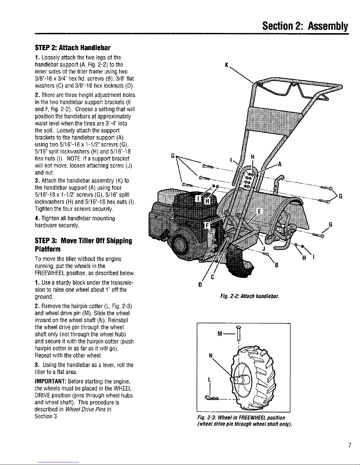
1. Looselyattach the two legs of the
handlebarsupport (A,Fig. 2-2) to the
inner sides of the tiller frame using two
3/8"-16 x3/4" hexhd, screws (B), 3/8' flat
washers (C) and 3/8"-16 hexIocknuts (D)
2. There are three height adjustment holes
in the two handlebar support brackets (E
and F,Fig. 2-2). Choosea setting that will
position the handlebars at approximately
waist level when the tines are 3"-4" into
the soil, Looselyattachthe support
bracketsto the handlebar support (A)
using two 5/16"-18 x 1-1/2' screws (G),
5/16" split Iockwashers (H) and5/16"-18
hexnuts (I) NOTE:If a support bracket
will not move, loosen attaching screw (J)
and nut.
3. Attach the handlebarassembly (K) to
the handlebar support (A) using four
5/16"-18 x 1-1/2' screws (G), 5/16" split
Iockwashers (H) and 5/16"-18 hexnuts (I).
Tighten the four screws securely
4. Tighten all handlebar mounting
hardware securely.
STEP3: MoveTiller OffShipping
Platform
To move the tiller without the engine
running, put the wheels inthe
FREEWHEELposition, as described below.
1. Use asturdy block under the transmis-
sion to raiseone wheel about 1' off the
ground.
2. Remove the hairpin cotter (L, Fig.2-3)
and wheel drive pin (M). Slide the wheel
inward on the wheel shaft (N). Reinstall
the wheel drive pin through the wheel
shaft only (not through the wheel hub)
and secure it with the hairpin cotter (push
hairpin cotter in as far as it will go).
Repeatwith the other wheel.
3. Usingthe handlebaras a lever, roll the
tiller to a flat area.
IMPORTANT:Beforestarting the engine,
the wheels must be placedin the WHEEL
DRIVEposition (pins through wheel hubs
and wheelshaft). Thisprocedure is
described in WheelDrive Pins in
Section 3.
Section2: Assembly
K
J
Fig. 2-2:A_achhnndleba_
H
L
Fig.2-3: WheelinFREEWHEELposition
(wheeldrivepinthroughwheelshaftonly).
7
Section2: Assembly
STEP4: Install ForwardClutchCable
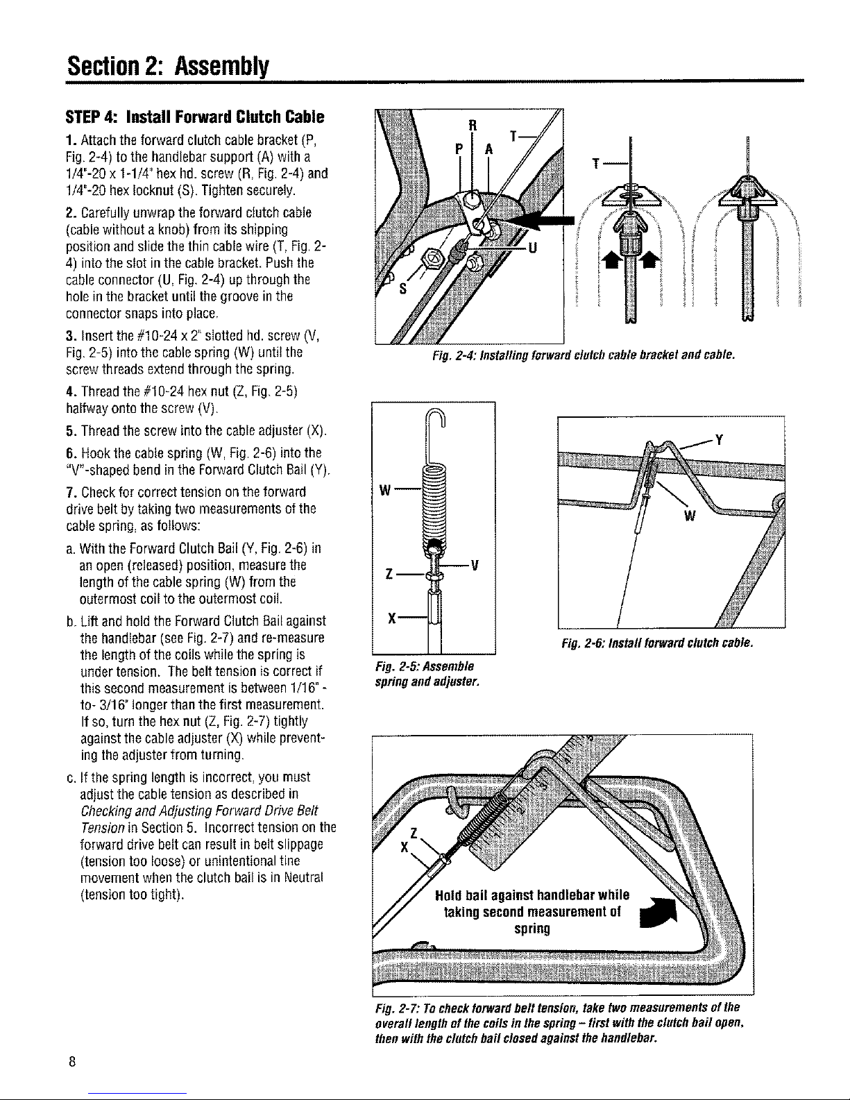
1. Attach the forward clutch cablebracket (P,
Fig. 2-4) to the handlebarsupport (A) with a
1/4"-20 x 1-1/4" hex hd. screw (R, Fig. 2-4) and
1/4"-20 hexIocknut (S). Tighten securely.
2. Carefully unwrap the forward clutch cable
(cablewithout a knob) from its shipping
position and slide the thin cable wire (T, Fig.2-
4) into the slot in the cable bracket. Pushthe
cableconnector (U, Fig,2-4) up through the
hole in the bracket until the groove in the
connector snaps into place,
3. Insert the #10-24 x 2"slotted hd.screw (V,
Fig. 2-5) intothe cablespring (W) until the
screw threads extend through the spring.
4. Thread the #10-24 hex nut (Z, Fig.2-5)
halfwayonto the screw (V).
5. Thread the screw into the cableadjuster (X).
6. Hook the cable spring (W, Fig. 2-6) into the
"W-shaped bend inthe Forward Clutch Bail(Y).
7. Checkfor correct tension on the forward
drive belt bytaking two measurements ofthe
cable spring, as follows:
a. With the Forward Clutch Sail (Y, Fig.2-6) in
an open (released) position, measurethe
length of the cable spring (W) from the
outermost coil to the outermost coi!.
b. Lift and hold the Forward Clutch Bail against
the handlebar (see Fig. 2-7) and re-measure
the length of the coils while the spring is
under tension. Thebelt tension is correct if
this second measurement is between 1/16"-
to- 3/16" longer than thefirst measurement.
If so, turn the hex nut (Z, Fig. 2-7) tightly
against thecable adjuster (X) while prevent-
ing theadjuster from turning.
c. If the spring length is incorrect, you must
adjust the cable tension asdescribed in
Checkingand Adjusting Forward Drive Belt
Tension in Section 5. Incorrect tension on the
forward drive belt can result in belt slippage
(tension too loose) or unintentional tine
movement whenthe clutch bail is in Neutral
(tension too tight),
Fig, 2-4: Installingforward clutchcable bracketand cable.
w--I
Z-- V
X--
Fig. 2-5:Assemble
springand adjuster.
w
Fig, 2-6: Install forwardclutchcable,
ii
Fig. 2-7: Tocheckforwardbelt tension, take twomeasurements ofthe
overall length of the coilsin the spring- first with the clutch bail open,
then withthe clutch bail closedagainstthe handlebar.
Section2: Assembly
STEP5: Check Level of
Transmission Gear Oil
Thetransmissionwasfilledwithgearoil
atthefactory.However,youshouldcheck
thegearoillevelto makecertainit is
correct,
IMPORTANT:Do not operate the tiller if
thegear oil level is low. Doingso will
result in severe damageto the transmis-
sion components,
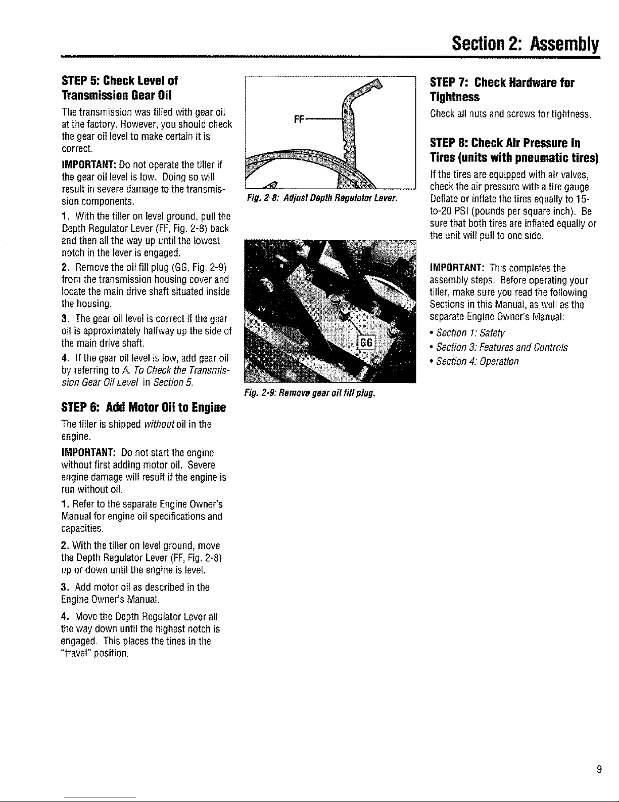
1. With the tiller on levelground, pull the
Depth Regulator Lever (FF,Fig. 2-8) back
and thenall the way up until the lowest
notch in the lever is engaged.
2. Removethe oil fill plug (GG,Fig.2-9)
from the transmission housing coverand
locate the main drive shaft situated inside
the housing.
3. Thegear oil level is correct if the gear
oil is approximately halfway up the side of
the main drive shaft.
4. If the gear oil levelis low, add gear oil
by referring to A. ToCheckthe Transmis-
sion Gear Oil Level in Section 5,
STEP6: Add Motor Oil to Engine
Thetiller is shipped withoutoil in the
engine.
IMPORTANT:Do not start the engine
without first adding motor oil Severe
engine damagewill result if the engineis
run without oil.
1. Referto the separate EngineOwner's
Manual for engine oil specifications and
capacities,
2. With the tiller on level ground, move
the Depth Regulator Lever (FF,Fig, 2-8)
up or down until the engine is level.
3. Add motor eli as described in the
EngineOwner's Manual.
4. Movethe Depth Regulator Leverall
the way down until the highest notch is
engaged. This placesthe tines in the
"travel" position.
Fig. 2-8: Adjust DepthRegulator Lever.
Fig,Z-9:Removegearoilfill plug.
STEP7: Check Hardware far
Tightness
Checkall nutsandscrewsfortightness,
STEP 8: Check Air Pressure in
Tires(unitswith pneumatictires)
If the tires areequipped with air valves,
checkthe air pressurewith a tire gauge.
Deflateor inflate the tires equallyto 15-
to-2g PSI (pounds per square inch), Be
surethat both tires are inflated equallyor
the unit will pull to oneside.
IMPORTANT: This completes the
assembly steps, Beforeoperatingyour
tiller, make sure you readthe following
Sections in this Manual, as well as the
separate Engine Owner'sManual:
• Section 1:Safety
• Section3: FeaturesandControls
• Section4: Operation
9
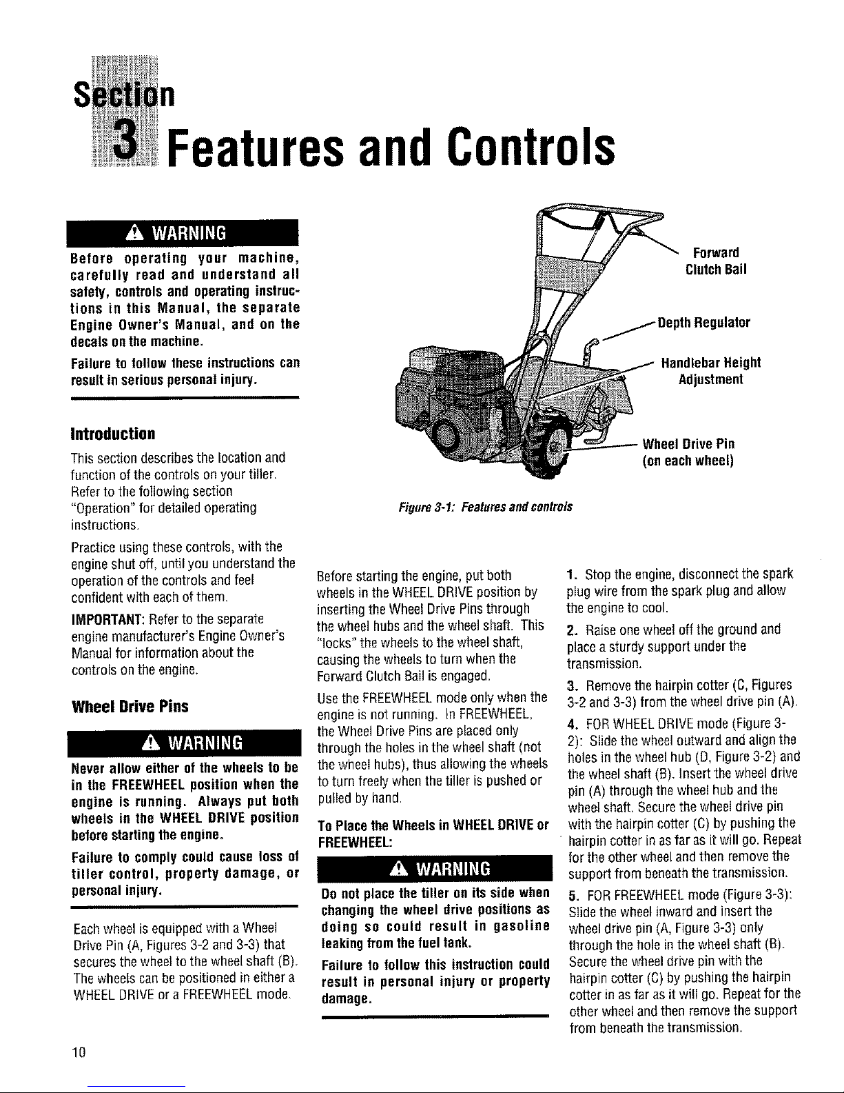
FeaturesandControls
Before operating your machine,
carefully read end understand all
safety, controls and operating instruc-
tions in this Manual, the separate
Engine Owner's Manual, and on the
decalson the machine.
Failure to follow these instructionscan
resultin seriouspersonal injury.
Forward
ClutchBail
_ DepthRegulator
HandlebarHeight
Adjustment
Introduction
This section describes the location and
function of the controls on your tiller.
Referto the following section
"Operation" for detailed operating
instructions.
Practiceusing these controls, with the
engine shut off, until you understand the
operation of the controls and feel
confident with each of them.
IMPORTANT:Refer to the separate
enginemanufacturer's EngineOwner's
Manualfor informationabout the
controls on the engine.
Wheel Drive Pins
Never allow either of the wheels to be
in the FREEWHEELposition when the
engine is running. Always put both
wheels in the WHEEL DRIVE position
beforestartingthe engine.
Failure to comply could cause loss of
tiller control, property damage, or
personalinjury.
Eachwheel is equipped with aWheel
Drive Pin (A, Figures3-2 and 3-3) that
securesthe wheelto thewheel shaft (B),
Thewheels can be positioned in either a
WHEELDRIVEor a FREEWHEELmode.
10
Figure3-1: Featuresandcontrols
Beforestarting the engine, putboth
wheels in the WHEELDRIVEposition by
inserting the Wheel Drive Pinsthrough
the wheel hubsand the wheel shaft. This
"locks" the wheelsto thewheel shaft,
causing the wheels to turn when the
Forward ClutchBail is engaged.
Use the FREEWHEELmodeonly when the
engine is not running. In FREEWHEEL,
the Wheel Drive Pinsare placed only
through the holes in the wheel shaft (not
the wheel hubs), thus allowing the wheels
to turn freely whenthe tiller is pushedor
pulled by hand.
To Place the Wheels in WHEELDRIVEor
FREEWHEEL:
Do not placethe tiller on its side when
changing the wheel drive positions as
doing so could result in gasoline
leaking fromfhefueltanko
Failure to follow this instructioncould
result in personal injury or property
damage.
Wheel Drive Pin
(on eachwheel)
1. Stop the engine,disconnect the spark
plug wire from the spark plug and allow
the engine to cool.
2. Raiseone wheel off the ground and
placea sturdy support under the
transmission,
3. Removethe hairpin cotter (C, Figures
3-2 and 3-3) from the wheel drive pin (A).
4. FORWHEELDRIVEmode (Figure 3-
2): Slide the wheel outward and align the
holes in the wheelhub (D, Figure3-2) and
thewheel shaft (B), Insert the wheel drive
pin (A) through the wheelhub and the
wheel shaft, Securethe wheel drive pin
with the hairpin cotter (C) by pushing the
hairpin cotter in as far as it will go. Repeat
for the other wheel and then removethe
support from beneaththe transmission.
5. FORFREEWHEELmode (Figure3-3):
Slide the wheel inward and insert the
wheeldrive pin (A, Figure 3-3) only
through the hole in the wheel shaft (B),
Securethe wheeldrive pin with the
hairpin cotter (C) by pushing the hairpin
cotter in as far as it will go. Repeatfor the
other wheel and then removethe support
from beneaththe transmission.

Section3: FeaturesandControls
0 1
Figure3-2: WHEELDRIVEposition.
01
B
Figure33: FREEWHEELposition.
Beforestarting the engine, be sure that
both wheels are in the WHEEL DRIVE
position. See "Wheel Drive Pins" for
instructions.
Engagingthe Forward ClutchBail when
the wheels are not in the WHEELDRIVE
positioncould allowthe tines to rapidly
propelthe tiller forward.
Failure to comply couldcause loss of
tiller control, property damage, or
personalinjury.
Forward Clutch Bail
TheForward Clutch Bail (E, Figure3-4)
controls the engagementof forward drive
to the wheels and tines.
To Operatethe ForwardClutchBail:
1. Put the wheels in the WHEELDRIVE
position (seethe "WARNING"statement
above),
2. Lift and hold the bail against the
handlebar. The wheels and tines wilt
rotate in a forward direction.
3. Releasethe bail to disengage (stop)
the wheels andtines. All forward motion
will stop (the engine will continue to run).
'E
Figure34: ForwardClutchBail(E).
DepthRegulatorLever
This lever (G, Figure 3-5) controls the
tilling depth of the tines. Pull the lever
straight back and slide it up or down to
engagethe notched height settings.
Thehighest notch (lever all the way down)
raisesthe tines approximately 1-1/2' off
the ground. This "travel" setting allows
the tiller to be moved without the tines
digging into the ground. Also usethis
setting when starting the engine.
Move the lever upwardto increasethe
tilling depth. Thelowest notch allows a
tilling depth of approximately 6",
depending on soi! conditions.
Forbest results,always begintilling at
a veryshallow depthsettingand
graduallyincreasethe tilling depth.
Travel
Position ,_ G
Deep
gs
Figure3-5,"DepthRegulatorLever (G).
• Do notattemptto till 1o0deeplytoo
quickly.Graduallyworkdownto
deepertilling depths.
• Place the Depth Regulator Lever in
the "travel" position before starting
the engine. This position prevents
the tines from touching the ground
until youare readyto begintilling.
Failure to follow this warning could
result in personal injury or property
damage.
HandlebarHeightAdjustment
The handlebar height is adjustable to
three different settings (see Figure 3-6).
As a generalrule, adjust the handlebars
so they are at waist levelwhen the tines
are 3"-4"into the soil.
To AdjusttheHandlebars:
1. Stop the engine,disconnect the spark
plug wire from the spark plug and allow
the engineto cool.
2. Removethe screws, Iockwashers and
nuts, reposition the handlebars,and
reinstall the hardware.
Figure3-6:Handlebarheightadjustment.
ENGINECONTROLS
Referto the enginemanufacturer's Engine
Owner's Manual (included in the tiller lit-
eraturepackage)to identify the controls
on your engine,
IMPORTANT:Thecontrol for stopping the
engine islocatedon the engine.
11

n
Operation
Before operating your machine,
carefully read and understandall safety
(Section 1), controls (Section 3) and
operating instructions (Section 4) in
this Manual, in the separate Engine
Owner'sManual, and on the decals on
the machine.
Failureto follow these instructionscan
resultin seriouspersona]injury.
\
ForwardClutchBail
_lator Lever
INTRODUCTION
Readthis Section of the manual thor-
oughly before you start the engine, Then,
takethe time to familiarizeyourself with
the basic operation of the tiller before
using it in the garden, Findanopen, level
areaand practice using thetiller controls
without the tines engaging the soil (put
tines in "travel" setting), Onlyafter
you've becomecompletely familiar with
the tiller should you begin using it in the
garden.
BREAK-IN OPERATION
Perform the following maintenance
during thefirst hours of new operation
(see"Maintenance" Section in this
Manualand in the Engine Owner's
Manual).
1. Changeengine oil after first 2 hours of
new engineoperation,
2. Checkfor looseor missing hardware
on unit. Tighten or replaceas needed.
3. Checktension on forward drive belt
after first 2 hours of operation.
4. Checktransmission gearoil level after
first 2 hours of operation.
Recoil Starter
Figure4-1
STARTINGANDSTOPPING
THE ENGINE
Pro-StartChecklist
Makethe following checks and perform
thefollowing services beforestarting the
engine.
1. Readthe "Safety" and "Controls"
Sections in this Manual. Readthe
separateEngineOwner's Manualprovided
bythe engine manufacturer.
2. Checkthat the wheels are in the
WHEELDRIVEposition (wheel pins must
be through the wheel hubs and thewheel
shaft holes).
3. Checkunit for looseor missing
hardware. Serviceas required.
4. Checkengine oil level. SeeEngine
Owner's Manual.
5. Checkthat all safety guards and
covers are in place,
6. Checkair cleanerandenginecooling
system. SeeEngineOwner's Manual,
7. Attach spark plug wire to spark plug.
Wheel Drive Pin
(on eachwheel)
GASOLINEIS HIGHLYFLAMMABLEAND
ITS VAPORSAREEXPLOSIVE.
Follow gasoline safety rules in this
Manual (see Section 1) and in the
separateEngineOwner'sManual.
Failure to follow gasoline safety
instructions can result in serious
personalinjury and propertydamage.
8. Fillthefuel tank with gasoline
according to the directions in the separate
EngineOwner's Manual, Follow all
instructions and safety rules carefully.
12

Section4: Operation
Starting the Engine
Thefollowing steps describe how to start
and stop the engine. Do notattempt to
engagefhe tines or wheelsuntil you
haveread all of the operatinginstruc-
tionsin this Section. Also review
the safetyrules in Section1: Safetyand
thetiller and engine controls
informaUonin Section 3: Featuresand
Controls.
To help prevent serious
personal injury or damage to
equipment:
• Before starting engine, put both
wheels in the WHEEL DRIVEposition.
Never have the wheels in the
FREEWHEEL position when the
engine is running. When the wheels
are in FREEWHEEL,they do not hold
back the tiller and the tines could
propelthe tiller rapidlyforward.
• Before starting engine, put Forward
Clutch Bail in neutral (disengaged)
positionby releasing lever.
• Never run engine indoors or ifl
enclosed, poorly ventilated areas.
Engine exhaust contains carbon
monoxide, an odorless and deadly
gas.
*Avoid engine muffler and nearby
areas. Temperatures in these areas
may exceed150°F.
1. Completethe Pre-StartCheckliston
the previous page.
2. Put the wheels in the WHEELDRIVE
position (see Wheel Drive Pinsin
Section 3).
3. Putthe DepthRegulator Leverin the
"travel" position (lever all the way down)
so that the tines are clear of the ground.
4. Releaseall controls on the tiller.
5. If engineis equipped with a fuel valve,
turn valve to open position as instructed
in the separateEngine Owner's Manual.
6. PutThrottle Control Leveron engine in
"ON", "RUN", "FAST"or "START"position
asinstructed in the separateEngine
Owner's Manual.
7. Chokeor prime engineas instructed in
the separate EngineOwner's Manual.
8. Placeone hand on the fuel tank to
stabilizethe unit when you pull the starter
handle. Usethe recoil starter rope to start
the engine as instructed in the separate
EngineOwner's Manual. When engine
starts, gradually move choke lever(on
enginesso equipped)to "NO CHOKE",
"CHOKEOFF"or "RUN" position.
9. Usethe "FAST"throttle speedsetting
when tilling.
Keepaway from rotatingtines. Rotating
tines will cause injury.
Stoppingthe Engineend Tiller
1. To stop the wheels andtines, release
the Forward Clutch Bail,
2. To stop the engine,put the Throttle
Control Leveron the engine in the "OFF"
or "STOP" position.
OPERATINGTHETILLER
The following pages provide guidelines to
using your tiller effectively and safely in
various gardening applications. Besure
to read Tilling Tips & Techniquesin this
Section beforeyou actually put the tines
into the soil,
This is a traditional "standard-rotating-
tine" (SRT)tiller with forward rotating
tines. It operates completely differently
from "counter-rotating-tine" (CRT)tillers
or from front-tine tillers.
1. Followthe Pre-StartCheckliston the
previous page. Besure that thewheels
are in the WHEELDRIVE position.
2. Putthe DepthRegulatorLever in the
"travel" position (lever all the way down)
sothat the tines are clear of the ground,
Usethis position when practicing with
your tiller or when moving to or from the
garden. When you are readyto begin
tilling, you must move the Depth
Regulator Leverto the desired depth
setting (see Tilling Tips & Techniques).
3. Startthe engineand allow itto warm
up. When warm, put throttle control in
fast speed setting,
4. For forward motion of thewheels and
tines:
Figure4-2: Useonehandtoguidetiller
whenmovingforward.
(a)
(b)
Pull the Forward Clutch Bail up and
hold it againstthe handlebar. Release
the bail to stop forward motion of the
wheels and tines.
Asthe tiller moves forward, relax and
letthe wheels pui! the unit along while
the tines dig. Walk behind and a little
to one side of the tiller. Usea light
but secure grip with one hand onthe
handlebars, but keep your arm loose,
See Figure4-2. Letthe tiller move
aheadat its own paceand do not push
down on the handlebarsto try and
force the tiller to dig deeper-this
takesweight off the wheels, reduces
traction, and causesthe tines to try
and propel thetiller.
13

Section4: Operation
Donot pushdownonthe handlebarsto
tryto make thetiller till more deeply.
Thispreventsthewheels from holding
thetiller back andcanallow thetines
to rapidly propelthe filler forward,
whichcouldresult in lossofcontrol,
properlydamage, or personal injury.
5. To move the unit rearward:
(a) Look behind and exercise caution
when moving in reverse. Do nottill
while in reverse.
(b) Releasethe Forward Clutch Bail.
(c) Tilt the handlebar slightly upward until
the tines are out of the soil.
(d) Swingthe handlebarto the left so the
right wheel takesa "step" backward.
Next movethe handlebarto the right so
the left wheel takesa "step" backward.
(e) Repeatto "walk" the tiller rearward. If
longer distances needto be covered in
reverse,shut off the engine,then place
thetwo wheels in FREEWHEEL.
6. ToTurn the Tiller Around:
(a) Practiceturning the tiller in a level,
open area. Bevery careful to keep
your feet and legs away fromthe tines.
(b) To makea turn, lift the handlebars
until the engineand tines are balanced
over the wheels (Figure4-4). The
tines must beout of the ground while
turning the tiller.
(c) With the tiller balanced,push sideways
on the handlebar to move the tiller in
the direction of the turn (Figure4-5).
After completing the turn, slowly lower
the tines into the soil to resume tilling.
Figure4-3: Raise tines offgroundand look
behind whenmoving in reverse. Unitcan be
"fishtailed" backwardmanually fora short
distance, orrolled backward whenwheels
are in FREEWHEEL.)
Steppingthe Tiller andEngine
1. To stop the wheels and tines, release
the ForwardClutch Bail.
2. To stop the engine, put theThrottle
Control Leveron the engine in the "OFF"
or "STOP" position.
Beforetilling, contactyourtelephone or
utilities companyand inquire if under-
groundequipmentor lines are used in
your area. Their representativewill be
glad to answer your questionsand tell
yon if any of their equipment or lines
are buried underground on your
property.
I Turningthe Tiller Around
Figure4-4: Tobeginturn, lift handlebars
until engineand tinesare balanced over
wheels. Besure tinesare outofground.
Figure4-5". Withtiller balancedover
wheels (andtines outof the ground),
push handlebarssideways to turn ti!ler.
14

Section4: Operation
TillingTips& Techniques
Letthe tiller dothework
• Whiletilling, relax and letthe wheels
pull the tiller along while the tines do
the digging. Walk on the sidethat is
not yet finished (to avoid making foot-
prints in the freshly tilled soil) and
lightly, but securely grip the handlebar
with just one hand.See Figure4-2.
• Avoid pushing down on the handlebars
in an attempt to force the tiller to dig
deeper. Doing so takes the weight off
the powered wheels,causing them to
lose traction. Without the wheels
helping to hold the tiller back, the tines
will attempt to propelthetiller - often
causing the tiller to skip rapidly across
the ground. (Sometimes, slight
downward pressure on the handlebars
will help get through a particularly
tough section of sod or unbroken
ground, but in most casesthis won't be
necessaryat all.)
Tilling depths
• Avoid trying to dig too deeplytoo
quickly, especially when busting sod or
tilling soil that hasn't been tilled for
some time. Use shallow depth settings
(only an inch or two deep) for the first
passesthrough the garden area. With
eachsucceeding pass,adjust the depth
regulatorto dig another inch or two
deeper, (Watering the garden area a
few days prior to tilling will make tilling
easier, aswill letting the newlyworked
soil set for a day or two before making
a final, deeptilling pass.)
• Whencultivating (breakingupthe
surfacesoil around plants to help
destroy weeds), useveryshallow depth
settings to preventinjury to plantswhose
rootsoften growcloseto the surface. If
needed,lift up on the handlebarsslightly
to preventthe tines from diggingtoo
deeply. Cultivatingon a regularbasisnot
onlyeliminatesweeds,it alsoloosens
andaeratesthesoil for bettermoisture
absorptionandfasterplant growth.)
Avoidtillingwet, soggysoil
Tilling wet soil often results in large,
hard clumps of soil that can interfere
with planting. If time permits, wait a day
or two after heavyrainsto allow the soil
to dry beforetilling. Testthe soil by
squeezingit into a ball. If it compresses
too easily, it is too wet to till.
Avoidmakingfootprints
Whenpossible,walk on the untilled side
of the unitto avoid makingfootprints in
thefreshly tilled soil. Footprintscause
soil compaction that can hamperroot
penetrationand contributeto soil erosion.
Theycanalso "plant" unwantedweed
seedsbackinto the newlytilled soil.
Choosingcorrectwheel
and tinespeeds
With experience,you will find the "just
right" tilling depth and tilling speed com-
bination that is best for your garden.
Setthe engine throttle lever ata speed to
givethe engine adequatepower and yet
allow it to operate at the slowest possible
speed...atleast until you haveachieved
the maximum tilling depth you desire.
Fasterenginespeeds may be desirable
when making final passesthrough the
seedbedor when cultivating. Selection of
the correct engine speed, in relation to
the tilling depth, witl ensure a sufficient
power level to do the job without causing
the engineto labor.
Suggestedtilling patterns
When preparing a seedbed,go over the
same pathtwice in the first row, then
overlapone-half the tiller width on the
rest of the passes(see Figure4-6).
Whenfinished in one direction, make a
second pass ata right angle as shown
in Figure4-7. Overlapeachpass for
best results (in very hardground it
may takethree or four passesto thor-
oughly pulverizethe soil).
• If the garden sizewill not permit
lengthwise and then crosswise tilling,
then overlap the first passesby one-
half a tiller width, followed by succes-
sive passesat one-quarter width (see
Figure4-8),
• With planning, you can allow enough
room betweenrows to cultivate (see
Figure4-9). Leaveroom for the hood
width, plus enough extra room for
future plant growth.
Figure4-6
Figure4.7
.d
Figure4-8
.guro,-gIOI@I®I
15

Section4: Operation
TillingTips& Techniques
Clearingthe tines
Thetines have a self-clearing action
which helps to eliminate most tangling
of debris. However, occasionally dry
grass, stringy stalks or tough vines may
become tangled. Follow these proce-
dures to help avoid tangling andto clear
the tines, if necessary.
• To reducetangling, setthe depth
regulator deepenough to get maximum
"chopping" action asthe tines chop the
material againstthe ground. Also, try
to till under crop residues or cover
crops while they are green, moist and
tender.
• While power composting, try swaying
the handlebarsfrom side to side (about
6"to 12°). This "fishtailing" action
often clears the tines of debris.
• If tangling occurs on modelsequipped
with a poweredreverse, lift the tines
out of the soil and run thetiller in
reversefor a few feet. This reversing
action should unwind a good deal of
debris.
• It may benecessaryto remove the
debris by hand (a pocket knife will help
you to cut away the material).
Beforeclearing the tines by hand, stop
the engine, allow all moving partsto
stop and disconnect the spark plug
wire.
Failure to follow this warning could
resultin personal injury.
Tilling on slopes
If you must garden on sloping ground,
deasefollow two very important guide-
lines:
1.Till only on moderate slopes, neveron
steepinclines wherefooting is difficult
(review safety rules in the "Safety"
Section of this Manual).
2. We recommend tilling up and down
slopes rather than terracing. Tilling
vertically on a slope allows maximum
planting area andalso leavesroom for
cultivating.
IMPORTANT: When tilling on slopes, be
;urethe correct oil level is maintained in
the engine (check every one-half hour of
operation). The inclineof the slopewill
causethe oil to slant awayfrom its
normal level andthis canstarve engine
_artsof required lubrication. Keepthe
engine eli levelat thefull point at all
times!
A. Tilling up and downslopes:
-To keepsoil erosion to a minimum, be
sureto add enough organic matter to
the soil so that it hasgood moisture-
holding texture and try to avoid leaving
footprints or wheel marks.
• Whentilling vertically, try to makethe
first pass uphill as the tiller digs more
deeplygoing uphill than it does
downhill. In soft soil or weeds,you
may haveto lift the handlebars slightly
while going uphill. When going
downhill, overlapthe first pass by
aboutone-half the width of thetiller.
B. TerraceGardening:
• Whena slope is too steepor too short
for vertical tilling, it maybe necessary
to till acrossthe slope and create
terraced rows. Terraces are rows that
are cut intothe side of a slope, creating
a narrow, but flat areaon which to
plant.
• Ona longslope, you can makeseveral
terraces, one below the other.
• Terracesshould beonly 2-to-3 feet
wide. Diggingtoo far into the side of
the slope will expose poor subsoil that
is unproductive for plants.
• To create a terrace,start at thetop of
the slope and work down. Go back and
forth across the first row as shown in
Figure4-10.
• Eachsucceeding lower terrace is
started by walking below the terrace
you're preparing. For added stability of
the tiller, always keepthe uphill wheel
in the soft, newly tilled soil Do not till
the last 12" or more of the downhill
outside edgeof eachterrace. This
untilled strip helps prevents the
terracesfrom breaking apart and
washing downhill. It also provides a
walking path between rows.
o::ll *
O _ _""EPEAT
Figure4.10
C.Tilling across slopeswithout using
terraces:
• Ifvertical or terracing gardening aren't
practical for you, then you cantill
laterally across a slope. We don't
reallyrecommend this method as it can
create unsurefooting and invites soil
erosion.
• As in terrace gardening, start atthe top
of the slope and overlap the first pass
by half the width of the tiller. For added
stability of the tiller, always keepthe
uphill wheel in the soft, newlytilled soil.
16

Section4: Operation
POWERCOMPOSTING
Power composting simply meanstilling
under and burying in the soil all manner
of organic matter such as crop residues,
leaves,grass clippings and cover crops.
This materialwill decompose during the
non-growing season and add important
natural nutrients to the soil.
When power composting,do not keep
the Depth Regulator Lever at a deep
settingif the tiller jumps orbucks.
Ifjumping or buckingoccurs,movethe
DepthRegulator Lever down to one of
the shallower settingsand then slowly
increase the tilling depth on later
passes.
Failure to comply could result in loss
of tiller control, property damage or
personalinjury.
The firstplaceto begin iswith crop
residues such asleftover vines, stalks,
stems and roots. Powercompost these
crop residues as soon as they finish
bearing. The sooner this is done,the
better, as tender green matter is easierto
till under. Usethe deepest depth
regulator setting possible without causing
the engineto labor or the tiller to jump
ahead.
Standing cornstalks of reasonableheight
can be power composted. Pushing over
(but not uprooting) cornstalks will often
make it easier for your tiller to chop up
the stalks. Keepthe tines clearof
excessivetangling by "fishtailing" or fre-
quently using reverse. Make several
passes,then return a few days laterto
finish off any remaining stubble.
After tilling under crop residues,add more
organic matter such as leaves,grass
clippings and even kitchen scraps. When
tilled into the soil, this organic matterwill
decompose and add even more important
nutrients to the soil.
After power composting, you may want to
plant a "green manure" cover crop to
protect the soil during the off-season.
You simply grow a crop of clover, alfalfa,
buckwheat, peas,beans, rye grass, grain,
or kaleand then till it into the soi! prior to
the planting season.
LOADINGAND UNLOADINGTHE
TILLER
Loadingand unloadingthe tiller intoa
vehicle is potentially hazardous and
we don't recommend doing so unless
absolutely necessary, as this could
result in personal injury or property
damage.
However, if you must load or unload
the tiller, to!low the guidelines given
next.
• Beforeloading or unloading, stopthe
engine,wait for all parts to stop moving,
disconnect the spark plug wire and let
the engine and muffler cool.
• The tiller is too heavyandbulky to lift
safely by one person. Two or more
people should share the load.
• Usesturdy ramps and manually (engine
shut off) roll the tiller into andout of the
vehicle. Two or more peopleare needed
to do this.
• Ramps must bestrong enoughto
support the combined weight of the tiller
and any handlers. The ramps should
provide good traction to prevent
slipping; they should haveside rails to
guide the tiller along the ramps; andthey
should have a locking device to secure
them to the vehicle.
•The handlersshould wear sturdy
footwear that will help to prevent
slipping.
• Position the loading vehicle sothat the
ramp angle is asfiat as possible (the
less incline to the ramp, the better).
Turn the vehicle's engineoff andapply
its parking brake.
• When going up ramps, stand inthe
normal operating position and push the
tiller ahead of you. Havea personat
eachside to turn the wheels.
* When going down ramps, walk
backwardwith the tiller following you.
Keepalertfor any obstacles behindyou.
Position a person at eachwheel to
control the speed of the tiller. Nevergo
down ramps tilter-first, asthe tiller could
tip forward.
• Usewooden blocks to placeon the
downhill side of the wheels if you need
to stop the tiller from rolling down the
ramp. Also, usethe blocks to temporar-
ily keep the tiller in placeon the ramps
(if necessary), and to chock the wheels
in placeafter the tiller is in the vehicle.
• Whenthe tiller is inthe vehicle, prevent
it from rolling by engaging thewheels in
the WHEELDRIVE position. Chockthe
wheels with blocks and securely tie the
tiller down.
17

n
Maintenance
Before inspecting, cleaning or
servicingthe machine, shutoffengine,
wait for all moving partsto come to e
complete stop, disconnectspark plug
wire and move wire away from spark
plug. Remove ignition key on electric
start models.
Failureto followthese instructionscan
result in serious personal injury or
propertydamage.
REQUIRED MAINTENANCE SCHEDULE
Before Eve_ Eve_ As
PROCEDURE Each 10 30 Noted
Use Hou_ Hon_
Checkengine oil level
Cleanengine
Checkdrive belttension
Checknuts and bolts
Changeengine oil
Lubricate tiller
Service engineair cleanersystem
Checkgearoil levelin
transmission
Checktines for wear
Checktire pressure
(pneumatic tires only)
Service spark plug
And every5
operating hours
-r
* Changemorefrequentlyindustyordirtyconditions. Changeafterfirst2hoursof
break-in operation,
_ Check after first 2 hours of break-in operation.
• SeeEngine Owner'sManual forservice intervalsand instructions.
18

Section5: Maintenance
WARNINGBelore inspecting, cleaning or servicing the unit, shut off engine, wait for all t =,.-.,.
partsto come to a complete stop, disconnectspark plug wire and movewire away from spark
plug. Failure to follow these instructions can result in serious personal injury or
propertydamage.
TILLER LUBRICATION
Proper lubrication of the tiller is an
essential part of your maintenance
program. After every t0 operating
hours, oil or greasethe lubrication points
shown in Figure5-1 and described
below.
Usea good quality lubricating oil (#30
weight engine oil is suitable) and agood
quality general purpose grease (grease
that has a metal lubricant is preferred, if
available).
• Removewheels, cleanwheel shaft (A,
Fig.5-1) and apply thin coating of
greaseto shaft.
• Greaseback,front and sides of depth
regulator lever (g, Fig. 5-1).
• Removetines, clean tine shafts (C, Fig.
5-1) and inspect for rust, rough spots
or burrs (especially around holes). File
or sand smooth and coat ends of shaft
with grease.
• Oilthe threads on the handlebar height
adjustment screws and the handlebar
attachingscrews (D, Fig. 5-1).
D
A
Figure5-I
CHECKFOR OILLEAKS
Beforeeach use, checkyour tiller for
signs of an oil leak - usually a dirty, oily
accumulation either on the unit or on the
floor where it has beenparked.
A little seepagearound a cover or oil sea]
is usually not a cause for alarm. However,
ifthe oil drips overnight then immediate
attention is neededas ignoring a leak can
result in severetransmission damage.
If a cover isleaking, check for loose
screws. If the screws are tight, a new
gasket or oil seal may be required. If the
leakis from around a shaft and oil seal,
the oil seal probably needs to be replaced.
Seeyour authorized dealer or contact the
factory for service or advice.
IMPORTANT:Neveroperate the tiller if the
transmission is low on oil. Checkthe oil
levelafter every30 hours of operation and
whenever there is any oil leakage.
CHECK HARDWARE
Checkfor looseor missing hardwareafter
every10 operating hours. Tighten or
replacehardware beforeusing the tiller.
Besureto checkthe screws underneath
the tiller hood (lift the hood flap) that
securethe transmission cover andthe
Depth Regulator Leverto the transmis-
sion.
CHECKTIREPRESSURE(Models
withpneumatictires)
Checkthe air pressure in both tires.
Deflateor inflate both tires evenly from
t 5-to-20 PSI (pounds per square inch).
Besure that both tires havethe same air
pressure or the unit will tend to pull to
one side.
TRANSMISSIONGEAROIL SERVICE
Checkthe transmission gear oil levei after
every 30 hours of operation or whenever
you notice any oil leak, Operatingthe
tiller when the transmission is low on oil
canresult in severe damage.
A. To Checkthe Transmission
GearOil Level:
1. Checkthe gear oil levelwhen the trans-
mission is cool. Gearoil will expandin
warm operating temperatures and this
expansion will provide an incorrect oil
levelreading.
2. With the tiiler on level ground, pull the
Depth Regulator Leverall the way up.
3. Removethe oil fill plug (A, Fig.5-2)
from the transmission housing and locate
the main drive shaft situated inside the
housing.
4. Thegear oil level is correct ifthe gear
oil is approximately halfway up the side of
the main drive shaft.
5. Ifthe gear oil levelis low, add gear oil
as described next. If the gear oil levelis
okay,securely replacethe oil fill plug.
IMPORTANT:Do not operate the tiller if
the gear oil level is Iow. Doing so will
result in severedamageto the transmis-
sion components.
8. If addingonly afew ounces of gear
oil, use API rated GL-4 or GL-5 gear oil
having a viscosity of SAE140, SAE85W-
140 or SAE80W-90. if refilling an empty
transmission, use only GL-4 gear oil
having a viscosity of SAE85W-140 or
SAE140.
IMPORTANT: Do not use automatic
transmission fluid or motor oil inthe
transmission.
7. While checking frequently to avoid
overfilling, slowly add gear oil into the oil
fill hole until it reaches the halfway point
on the drive shaft.
8. Securelyreplacethe oiI fill plug,
B. To Drainthe TransmissionGearOil:
Thetransmission gear oil does not need
to be changed unless it has been contam-
inated with dirt, sand or metal particles.
1. Drain gasoline from the fuel tank or
run the engine until the fueI tank is
empty_See"DANGER" statement that
follows.
19

Section5: Maintenance
WARNING Before inspecting,cleaning or servicingthe unit, shut off engine, wait for all i
partsto come to a completestop, disconnectsparkplug wire and movewire away fromspark
plug. Failure to foliowthese instructions can result in serious personal injury or
propertydamage.
Gasoline is highly flammable and its
vapors are explosive. Follow these
safety practices to prevent personal
injury or propertydamage from fire or
explosion.
,, Allow the engine and muffler to cool
for at leasttwo minutesbefore draining
thetiller's gasolinetank.
• Do not allow open flames, sparks,
matchesor smokingin the area.
* Wipe away spills and pushtiller away
fromspilled fuel.
• Use only an approved fuel container
and store it safely out of the reach of
children.
• Do not store gasoline in an area
where its vapors could reach an open
flame or spark, or where ignition
sourcesare present(such as hot water
and space heaters, furnaces, clothes
dryers,stoves, electricmotors,etc.)
2. Drain the oil from the engine.
3. Removefour screws (B, Figure5-2) and
removetransmission cover and gasket.
4. Remove the left-side wheel.
5. Tilt the left-side wheel shaft into a
drain pan and allow the gear oil to drain
through the top of the transmission,
6. Reinstall the wheel, install a new
gasketcover (do not reuseold gasket)
and reinstall the transmission cover.
7. Refillthe transmission using GL-4
gear oil (SAE85W-140 or SAE 140).
8. Refillthe engine with motor oil and
replenish the fuel tank with gasoline.
BOLOTINES
The bolo tines will wearwith useand they
should be inspected atthe beginning of
eachtilling seasonand after every 30
operating hours. The tines can be
replacedindividually or as a complete set.
Seethe Parts Listfor tine identification
and part numbers,
2O
Figure5-2: Remove oil fiRplug (A) to check
gear ofl level and to addgear niL Remove
fourcoverscrews(B) todrain gear oil.
A, Tine Inspection:
With use,thetines will becomeshorter,
narrowerand pointed. Badlyworn tines
will result in a loss of tilling depth and
reducedeffectiveness whenchopping up
and turning under organic matter.
B. Removinga Single Tine:
1. With the engine shot offandthe spark
plug wire disconnected, removethe two
screws (A, Figure 5-3) and Iocknuts (B)
that attach a single tine to the tine holder.
If needed,use penetrating oil on the nuts.
2. When installing a single tine, besure to
position it so that its cutting edge will
enter the soil first asthe tiller moves
forward.
C. Removinga Tine Assembly:
1. A tine assembly consists of eight tines
mounted on atine holder.
2. If removing both tine assemblies, mark
them "left" and "right" before removal.
Removethe screw (C, Figure 5-3) and
Iocknut (D)that secure the tine assembly
to the tine shaft. If necessary,use a
rubber mallet to tap the tine assembly
outward off the shaft.
3. Before reinstalling thetine assembly,
inspect the tine shaft for rust, rough
spots or burrs andfile or sand as needed.
Apply a thin coat of greaseto the shaft.
4. Install eachtine assembly so that the
cutting edge of the tines will enter the
soil first when the tiller moves forward.
Securethe tine assembly to thetine shaft
using the screw and Iocknut previously
removed.
ENGINE
C
B
Figure5-3: Install tinesso thatcutting edgeof tinesenter softfirst whentiller moves forward.

Section5: Maintenance
WARNINGBefore inspecting,cleaning or servicingthe unit, shut off engine, wait for all 1_
parts to come to a complete stop, disconnectspark plugwire and movewire away from spark _,L._/
plug. Failure to follow these instructions can result in serious personal injury or
propertydamage.
CHECKINGAND ADJUSTING
FORWARDDRIVE BELTTENSION
Maintaining correct tension on the
forward drive bett is important to good
tilling performance and Iong belt life.
A loosebelt will slip on the engine and
transmission pulleys and causethe tines
and wheels to slow down - or stop com-
pletely- eventhough the engineis
running atfull speed. A beltthat is too
tight can result in unintentional tine
movement whenthe clutch bail is in the
Neutral (released)position.
Also check the belt for cracks, cuts or
frayed edgesand replace it as soon as
possible.
• Checkbelt tension afterthe first two
hours of break-inoperation (new belt).
• Checkbelt tension after every10
operating hour.
To CheckForwardBeltTension:
1. Stop the engine,wait for al! parts to
stop moving and disconnectthe spark
plug wire.
2. With the forward clutch bail inan open
(released)position, measureand carefully
notethe overall length of the cablespring
(A, Figure 5-4) by measuringfrom the
outermost coil to the outermost coil.
3. Lift and holdthe forward clutch bail
against the handlebar (see Figure5-4) and
re-measurethe overall lengthof the coils
while the spring is under tension. The belt
tension is correct if this second measure-
ment is between1/16"-to- 3/16" longer
than the first measurement.
4. If the spring is too short (less than
1/16" greaterthan the first measurement),
the tension is too loose. If the spring is
too long (more than 3i1B"greater than the
first measurement), the tension is too
tight.
5. To adjust the length of the spring:
a. Releasethe Forward Clutch Bail.
b. Unthread the hex nut (C, Figure5-4)
about halfway up the adjustment
screw (D).
c. Unhook the top of the spring from
the forward clutch bail.
d. Use pliers to preventthe adjuster (B)
from turning and turn the slotted
screw located inside the screw
clockwise (viewed from operator's
position) to increasetension on the
spring. Turn the screw counter-
clockwise to decreasetension on the
spring. Onceadjusted, re-hookthe
top of the spring to the forward
clutch bail. (Continue to Step 5e.)
e. RepeatSteps 2 and 3 to re-measure
thelength of the spring coils. When
the second measurement(with bail
closedagainst handlebar)is between
1/16"-to- 3/16" longerthan the first
measurement,retightenthe hexnut
(C)against the top of the adjuster (B).
ReplacementBelt Information
If the drive belt needsto be replaced,see
your local authorized dealeror referto the
Parts Listfor ordering information. Use
only afactory-authorized belt asan "over
the counter" belt maynot perform satis-
factorily. Theprocedure requiresaverage
mechanicaiability and commonly
availabletools.
FORWARDCLUTCH
BAILADJUSTMENT
If the Forward Clutch Baildoes not
function properly, first check that the
forward drive belt is adjusted properly
(see Checkingand Adjusting Forward
Drive Belt Tension). If this fails to correct
the problem, contact the factory technicai
servicedepartment or your authorized
dealerfor service advice.
Figure5-4: Tocheck forwardbelt tension, take two measuremenls of
the overall length of the coilsin the spring - first withthe clutchbai!
open, thenwith the clutchbail closedagainst the handlebar.
21

Section5: Maintenance
WARNING Before inspecting,cleaning or servicingthe unit, shut off engine, wait for all 1"
pads to come to a completestop, disconnectsparkplug wire and movewire away from spark ...._.../
plug. Failure to follow these instructions can result in serious personal injury or
propertydamage.
ENGINECLEANING
Keepthe engineclean to assure smooth
operation and to preventdamagefrom
overheating. Referto the separateEngine
Owner's Manualfor specific repair and
cleaning instructions. All inspections and
services must be done with the engine
shut off and cool to the touch.
AIR CLEANERSERVICE
Theengine air cleaner filters dirt and dust
out of the air before it enters the carbure-
tor. Operatingthe engine with a dirty,
clogged air filter can cause poor perfor-
manceand damageto the engine. Never
operatethe enginewithout the air cleaner
installed. Inspect and servicethe air
cleaner more often if operating in very
dusty or dirty conditions.
Service the air cleaner asinstructed in the
separate EngineOwner's Manual.
ENGINEOIL SERVICE
Checkthe engine oil level before starting
the engine each dayand check it after
each 5 hours of continuous operation.
Runningthe enginewhen it is low on oil
will quickly ruin the engine.
It is recommended that you change the
engine oil after every 10 hours of
operation and even sooner when
operating in extremely dirty or dusty con-
ditions. Refer to the separate Engine
Owner's Manualfor detailed service
instructions.
A. To Checkthe EngineOil Level:
1. Move the tiller to a levelareaand shut
off the engine.
2. Level the engine by putting the Depth
Regulator Leverin the second notch from
the top,
3. Cleanthe areaaround the oil dipstick
or oil fill tube to prevent dirt from falling
into the crankcase.
4. On engines with an oil fill tube, remove
thefiller cap, add oil (if required) until it
reachesthe top ofthe tube and reinstall
thefiller cap.
5. On engines with a dipstick, remove it,
wipe it clean, and reinstall it finger-tight.
Removethe dipstick and checkthe
reading. Add oil (if required) to bring the
levelto the FULLmark. Do not overfill.
B. To Changethe EngineOil:
Changethe engine oil asinstructed in the
separateEngineOwner'sManual.
SPARKPLUGSERVICE
inspect and clean or replacethe spark
plug after every 100 operating hours or
annually. Cleanthe plug and set the gap
asdescribed in the separateEngine
Owner's Manual.
In some areas,local lawrequires using
resistor spark plugsto suppress ignition
signals. If the engine was originally
equipped with a resistor spark plug, use
the same type for replacement.
SPARKARRESTERSCREEN
SERVICE
If the engine muffler is equippedwith a
spark arrestor screen, removeand clean
it according to the time intervals and
instructions in the separateEngine
Owner's Manual.
Operators shall not tamper with the
engine governor settings on the
machine; the governor controls the
maximum safe operating speed to
protect the engine and all moving
parts from damage caused by
overspeed.Authorizedserviceshall he
soughtit a problemexists.
THROTTLELEVERADJUSTMENT
If the enginedoes not respond to various
throttle lever settings, refer to the
separateEngineOwner's Manualfor
serviceinformation or contact your local
authorized engine servicedealer.
CARBURETOR/GOVERNOR
CONTROLADJUSTMENTS
Thecarburetor was adjusted atthe
factory for best operating speed. Referto
the separateEngineOwner's Manualfor
anyadjustment information or seeyour
authorized engine servicedealer.
Thegovernor controls the maximum safe
operating speed and protects the engine
and all moving parts from damage
causedby overspeeding Donot tamper
with the engine governor settings.
OFF SEASONSTORAGE
Whenthe tiller won't be usedfor
extendedperiods, prepare it for storage
asfollows:
1. Cleanthe tiller and engine.
2. Do routine tiller lubrication and check
for loose parts and hardware.
3. Protect the engine and perform recom-
mended engine maintenance byfollowing
the engine storage instructions found in
the separateEngine Owner's Manual.
NOTE:Besure to protect thefuel lines,
carburetor and fuel tank from gum
deposits by removing fuel or by treating
fuel with afuel stabilizer (follow engine
manufacturer's recommendations).
4. Store unit in a clean,dry area.
5. Neverstore the tiller with fuel in the
fuel tank in an enclosedarea where gas
fumes could reachan open flame or
spark, or where ignition sources are
present (space heaters,hot water
heaters,furnaces, etc.).
22

Section5: Maintenance
TROUBLESHOOTING
Beforeperforming any corrections, refer to the appropriate information in this Manual, or in the EngineOwner's Manual, for the
correct safety precautions and operating or maintenance procedures. Contactyour local authorized EngineService Dealerfor
engine service. Contactyour localauthorized equipment dealer or the factory for all other service problems.
PROBLEM POSSIBLE CAUSE CORRECTION
Enginedoes
not start.
!. Sparkplugwire disconnected.
2. EngineThrottleControILeverincorrectlyset.
3. FueItank empty.
4. ChokecontroI (if soequipped)in incorrect position.
5. StalegasoIine.
6. Dirty air filter(s).
7. Defectiveor incorrectlygappedsparkplug.
8. Carburetorout of adjustment.
9. Misadjustedthrottle control
10.Dirt or waterinfuel tank.
1. Reconnectwire.
2. Put leverin STARTposition.
3. Addfuel
4. SeeEngineOwner's Manual.
5. Drainfuel andaddfreshfuel.
6. Cleanor replacefilter(s).
7. Inspectspark plug.
8. SeeEngineServiceDealer.
9. SeeEngineServiceDealer
10. SeeEngineServiceDealer.
j Enginerunspoorly. 1. Defectiveor ineorrectiygappedsparkplug. 1. Inspectspark plug (seeEngineOwner'sManual).
2. Dirtyair fiIter(s). 2. CIeanor repIace(seeEngineOwner'sManual).
3. Carburetorout of adjustment. 3. SeeEngineServiceDealer.
4. Stalegasoline. 4. RepIacewith fresh gasoline.
5. Dirt or waterinfuel tank. 5, SeeEngineServiceDealer,
6. Enginecooling systemclogged. 6, CIeanair cooling system(seeEngineOwner'sManual).
Engineoverheats. 1. Enginecoolingsystemclogged, 1. Cleanaircoolingarea(seeEngineOwner'sManual).
2. Carburetorout of adjustment. 2. SeeEngineServiceDeaIer.
3. Oil levelis low. 3. Checkoil level(seeEngineOwner's Manual).
Enginedoesnot
shutoff. 1. Misadjustedthrottlecontrol or ignition switch. 1. SeeEngineOwner'sManualor EngineServiceDealer.
WheelsandTines 1. Improperuseof controls. 1. ReviewSections3 and4.
will notturn. 2. Worn. broken,or misadjusteddrive belt(s). 2. See"CheckingDriveBeltTension,"Section5.
3. Internaltransmission wearor damage. 3 Contactlocaldealeror the factory.
4. BoltIoosein transmissionpulley. 4. Tightenbolt.
Tinesturn,but 1. WheelDrivePinsnot in WHEELDRIVE. 1. See"WheeiDrive Pins"in Section3.
wheelsdon't, 2. Boltlooseintransmission pulley. 2.Tightenbolt.
3. internaltransmissionwearor damage. 3. ContactlocalDealerortheFactory.
WheelsTurn,but 1.Tine holdermounting hardwaremissing. 1. Replacehardware.
TinesDon't. 2. Bolttooseintransmission pulley. 2. Tightenbolt.
3_internaltransmissionwearor damage. 3. ContactlocalDealerortheFactory.
Poortilling 1. Worntines. 1. See"BoleTines" (Section5).
performance. 2. ImproperDepthRegulatorsetting. 2. See"TilIingTips &Techniques,"Section4.
3. incorrectthrottle setting. 3. SeeSection4.
4. Forv_ardDriveBeltslipping. 4. See"CheckingForwardDrive BeltTension,"Section5.
23

PARTSLIST Model12213
TINEHOOD,DEPTHREGULATORAND DRAGBAR •
15
17\
18
i
I
REF. PART
No. NO. DESCRIPTION QTY.
1 9552 Flange Screw,Self-Tapping,
1/4-20 x !/2 ................................... 2
3 1917536 Decal, Hood ....................................... 1
5 1918155 Tine Hood (Incl. tine flapand Ref. 3) _ 1
6 1100088 Hex Screw, 5/16-18 x 1/2 ................... 2
7 1186391 FIangeLook Nut, 5/16-18 .................... 2
8 1916118001 Depth ReguIator Lever........................ 1
8A 9308 Spirol Pin ............................................ 2
9 9384 Spring, DepthRegulator ..................... 1
10 9534 Spacer ................................................ 1
11 1100069 Hex Screw, !/4-20 x 1......................... 1
12 9811 Locknut, 1/4-20 .................................. 1
REF. PART
NO. NO. DESCRIPTION QTY.
13
14
15
16
17
18
19
20
1916119001
1916120001
11000242
1186331
1186230
1100808
55088
1916121001
Hood Bracket,Right Hand................... 1
Hood Bracket,Left Hand..................... 1
Lockwaeher,5/16................................ 2
FlangeScrew, 5/16-18 x 1 ................. 2
HexNut, 5/16-18................................. 2
Hex Hal.Screw,5/16-18 x 1-1/4.......... 2
Bushing............................................... 2
DragBar.............................................. 1
24

Mo .112213 PARTSLIST
BOLOTINESANDWHEELS
HoldTine With BluntEndTowardYou
LeftHandTine
Right HandTine
NOTE:IdentifyLeftend Rightsides eftiller by standingin
operatorpositionandfacing directionof forwardtravel.
lo
7
FRONT/
FORWARD
_WHEEL
i SHAFT
FRONT/
FORWARD
10
LEFTSIDE
RIGHT SIDE
REF. PART
No. NO. DESCRIPTION QTY.
9711
50049-01
3 1733398
4 9556
.... 1901
HexScrew,3/8-16x 1, Grade5............. 16
8oloTine-RightHand.Singletineused
onleftsideo1tiller.(Incl.two each
Refs.1 & 3)....................................... 8
HexLocknut,3/8-16.............................. 18
HexScrew,3/8-16x 1-3/4.................... 2
8oloTineReplacementSet (Incl.eight
righthandtines,eightleft handtines
andrequiredhardware...................... 1
REF. PART
No, No. DESCRIPTION QTY.
5 50049-02 8oloTine- LeftHand, Singletineused
on rightsideoftifler. (IncLtwo each
Refs.1 & 3)....................................... 8
1916747001 TineHolder........................................... 2
1917486 WheeI&TireAssembly......................... 2
9380 ClevisPin,.312"x 1-3/4"....................... 2
9338 HairPinCotter....................................... 2
6
7
9
10
25

PARTSLIST Model12213
HANDLEBARS, CLUTCH CABLEAND HANDLEBAR MOUNTING HARDWARE
22_
6
24
7
11
\
9
17
14
\ _13
19
26

Modol1221a PARTSLIST
REF.
NO.
1
2
3
4
5
6
7
8
9
10
11
I2
13
HANDLEBARS, CLUTCH CABLEAND HANDLEBAR MOUNTING HARDWARE
PART
No. DESCRIPTION QTY.
1916909
1916928
1100799
1100806
55044
1916106O01
9855
1916712
1100242
1186230
9811
55048
1100068
UpperHandlebar(Incl.Ref.2) ............ 1
Decal,ForwardClutchBail.................. 1
HexHd.Screw,5/16-18x1-1/2 .......... 6
HexScrew,1/4-20x1-1/4................... I
Bracket,ForwardClutchCable............. 1
Bail,ForwardClutch............................ 1
Screw,#10-24x2............................... 1
Spring,ForwardClutch........................ 1
Lockwasher,5/16................................ 6
HexLocknut,5/16-18.......................... 6
HexLocknut,1/4-20............................ 1
CableAssy,ForwardClutch................. 1
HexScrew,3/8-16x3/4...................... 2
REF. PART
NO. No. DESCRIPTION QTY.
14 9837
15 1107383
16 1100044
17 1916107001
18 1110107
19 1916108001
20 9386
21 9856
22 9552
23 1901273010
24 1917559
27 1186227
HexLocknut,3/8-16............................ 2
FlatWasher,3/8 .................................. 2
HexScrew,5/16-18x3/4.................... 2
HandlebarSupport.............................. 2
HexLocknut,5/16-18.......................... 2
LowerHandlebar................................. 1
KlipRing.............................................. 1
ClevisPin............................................. 1
HexScrew,1/4-20x 1/2,Self-Tap....... 4
Panel...................................................1
Decal,ModelName/Logo................... 1
HexNut,#!0-24 .................................. 1
DRIVE SHAFT ASSEMBLY
1
2
3
10
REF. PART
No. No. DESCRIPTION QTY.
1 1100004
2 9944
3 1911321
4 9301
5 50027
6 9517
7 1714
B 50043
9 1904281
10 1224-1
1224-2
1224-3
1224-4
1325C
HexScrew,5/16-24x3/4,Grade5......... 1
BellevilleWasher................................... 1
TransmissionPulley............................. 1
Key,TransmissionPulley,3/16 x 1....... 1
SupportWasher,Front.......................... 1
SnapRing.............................................. 1
Bearing,TaperedRoller(with race)....... 2
SupportWasher,Rear........................... 1
DriveShaftAssy.................................... 1
Shim,RearBearingCap,.010"thick ..... NR
Shim,sameasabove,except
.030"thick.........................................A/R
Shim,sameasabove,except
.005"thick.........................................NR
Shim,sameasabove,except
.062"thick.........................................A/R
ShimSet(IncLthefollowingshims:
two#1224-1,two1224-2,
one1224-3,andone#1224-4)......... A!R
A/R- As Required
27

PARTSLIST Model12213
WHEELANDTILLERSHAFTASSEMBLIES
3
2
FRONT
[ 7
I
4
I
3
i 7
i
4
6
!
4
7
2
3
7
10
J 9
I :
2
3
REF. PART
NO, NO, DESCRIPTION QTY.
1
2
3
9512 Retainer,Snap Ring, <'E"Type........... 2
9511 Retainer,Snap Ring.......................... 4
1166-1 Shim, 0.062" thick ............................. #JR
1166-2 Shim, 0.030" thick ............................. #JR
1166-3 Shim, 0.015" thick ............................. #JR
1166-4 Shim, 0.010" thick ............................. #jR
1166-5 Shim, 0.005" thick ............................. #JR
1086 BronzeBushing ................................. 4
REF. PART
NO. NO. DESCRIPTION QTY.
5 1916741 WheelShaft ............................ 1
6 9305 Key,HiPro,1/4x 1........................... 1
7 1132-2 Spacer............................................;.. 4
8 1904278 WormGear,WheelShaft................... 1
9 1915074 TillerShaft......................................... 1
1g 1104 Woodruff Key................................... 1
11 1904279 WormGear,TillerShaft..................... 1
AtR- AsRequired
28

Model 12213 PARTSLIST
TRANSMISSIONHOUSING,COVERS,SEALS,GASKETSANDPLUG
12
11
15 /
14
REF. PART
NO. NO. DESCRIPTION QTY.
129727
1186328
5 1916641OO1
5A 50074
6 50032
7 9617
8 9621
Plug,TransmissionOilFill.................. 1
FlangeScrew,5/16-18x 5/8,
Grade5 .......................................... 8
FrontCover,Transmission.................. 1
RearCover,Transmission................... 1
Gasket,HousingCover........................ 2
OilSeal DriveShaft............................ 1
OilSeal,WheelSha_........................... 2
REF. PART
No. No. DESCRIPTION QTY.
9 1915084010
10 1909374
11 55011-1
55011-2
12 1916111001
13 1186331
14 1100044
!5 11OO242
TransmissionHousingAssy................ 1
OilSeal,TineShaft............................. 2
BearingCapGasket,.010"thick ......... 1
BearingCapGasket,.g30"thick.......... 1
RearBearingCap ............................... 1
FlangeScrew,5/16-18x 1 ................. 2
FlangeScrew,5/16-18x3/4 ............... 1
Lockwasher,5/16................................ 1
29
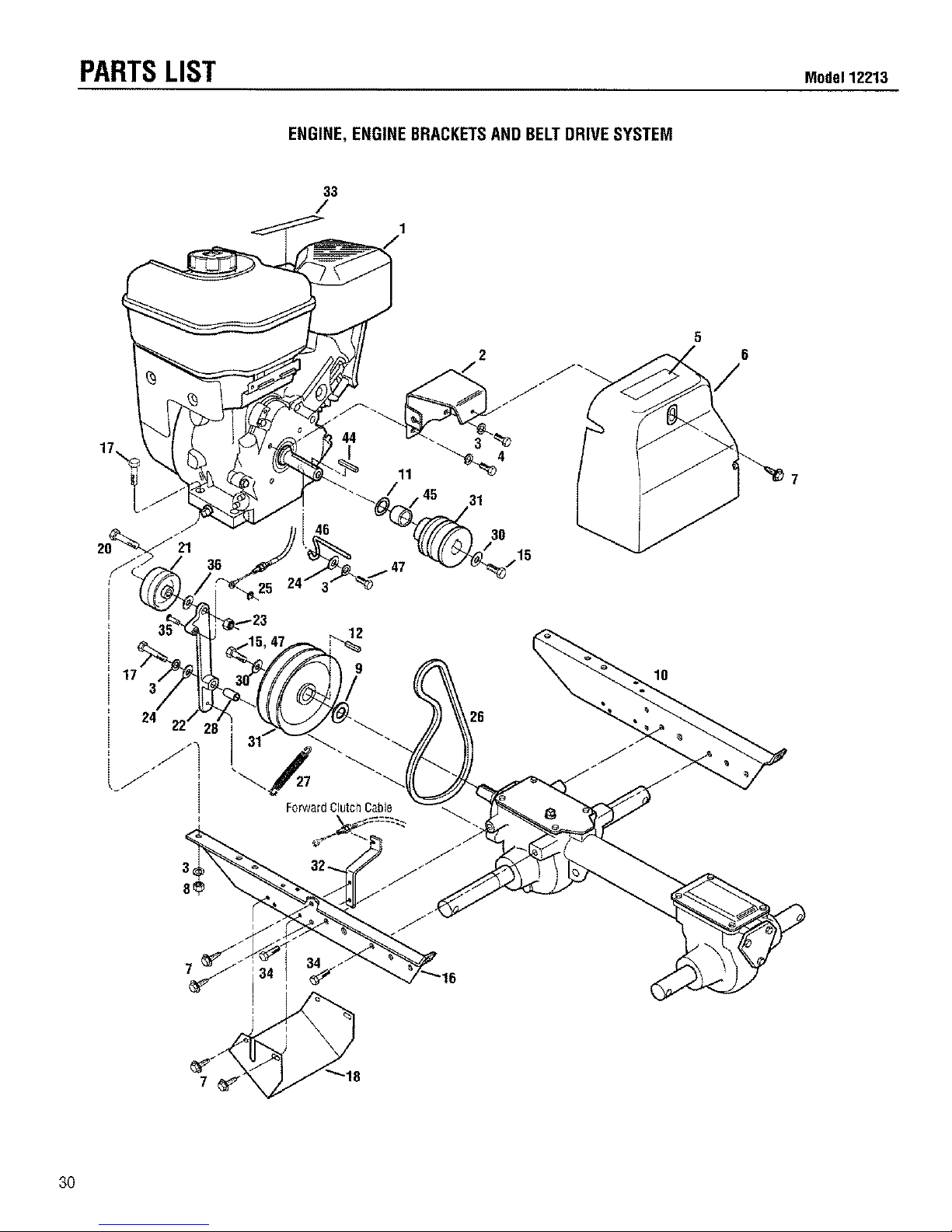
PARTSLIST Mod°112:,13
ENGINE,ENGINEBRACKETSANDBELTDRIVESYSTEM
33
/
2 6
3
24
7
12
9
ForwardClutch Cable
10
3O

Modet12213 PARTSLIST
ENGINE,ENGINEBRACKETSANDBELTDRIVESYSTEM
REF. PART
NO. NO. DESCRIPTION QTY.
1
2
3
4
5
6
7
1917326001
1100242
1111696
1904557
1917128
9552
8 1186230
9 50027
10 1916795001
11 1138_2
12 9301
13 1911322
15 1100005
16 1916794001
17 1100799
18 1916652001
20 9558
21 9090
Engine, RecoilStart............................. 1
Bracket,Belt Cover.............................. 1
Lockwasher, 5/16 ............................... 8
Hex Hd,Screw, 5/16-24 x 1/2 ............ 2
Decal,Hot SurfacesWarning ............. 1
Belt Cover (Incl. Ref. 5)....................... 1
FlangeScrew, Self-Tapping,
1/4-20 x 1/2 .................................... 7
Hex Nut,5/16-18 ................................. 4
Support Washer.................................. !
EngineBracket, Right ......................... 1
Shim ................................................... AIR
Key,3/16" x 1",.................................... 1
Putley,EngineDrive ........................... 1
Hex Screw,5/16-24 x 1....................... 3
EngineBracket, Left............................ 1
Hex Screw,5/16-1B x 1-1/2 ................ 5
Guard,Belts/Pulleys............................ 1
Hex Screw,3/8-16 x 1-!/2 .................. 1
Forwardidler Pulley ............................ 1
REF. PART
NO. NO. DESCRIPTION QTY.
22 1916116001
23 1110108
24 1107382
25 9386
26 1916657
27 55034
28 55033
30 9944
31 1911321
32 1916117001
33 1900766
34 1186328
35 9856
36 1107383
44 1108841
45 1916574
46 1916706
47 1100004
ForwardIdlerLever............................. 1
Locknut,3/8-16.................................. 1
FlatWasher......................................... 2
KlipRing............................................. 1
ForwardDriveBelt.............................. 1
ForwardReturnSpring........................ 1
Bushing,ForwardIdlerLever.............. 1
BellevgleWasher................................. 1
TransmissionPulley............................ 1
Bracket,CableMounting..................... 1
Decal,Stabilization.............................. 1
HexScrew,5/16-18x5/8 ................... 4
ClevisPin............................................ 1
FlatWasher,3/8.................................. 1
Key,3/16x !-1/2 ................................ 1
Spacer................................................ 1
ForwardBeltGuide............................. 1
HexHd.Screw,5/16-24x 3/4 ............ 2
A/R- AsRequired
* Contactyour localauthorizedengineservicedealerfor enginepartsand
service,Referto yourenginenameplatefor enginemodel/typenumber.
31

CUSTOMERSERVICEINFORMATION
OwnerRegistrationCard
Pleasefill out and mail the enclosed owner
registration card. Thepurpose of this card is
to register each unit at the factory so that we
canprovide you with warranty benefitsand
informational bulletins. ,J_;_'__
WarrantyService
Thewarranty statementis included inthe unit's literature
package.
Model/SerialNumbers
A Model/Serial Numbers decal is locatedon top of the trans-
mission. For readyreference, recordthese numbers in the
spacesbelow.
Dateof Purchase:
Model/Serial Numbers:
AuthorizedDealer Information
If you purchasedyour unit from an authorized dealer, record
the dealer'saddress and phone number below for ready
reference:
DealerName:
Address:
Phone:
IMPORTANT:
Leftandright sidesof the unit are determined bystanding
behindthe unit, in theoperator's position,andfacing in the
directionofforwardtravel.
NOTICE:
We reservethe rightto changespecifications,add
improvementsordiscontinuethe manufactureof anyof our
equipmentwithoutnotice or obligationto purchasersofour
equipment.
CustomerServiceand TechnicalService
Ifyou havequestions or problems with the
unit, contact your IocaIdealer or thefactory.
(Whencalling or writing, provide the
Model/Serial Numbers of the unit.)
ReplacementParts
Factoryspecified replacement parts are
availablefrom your authorized dealer or
directly from the factory. When ordering
parts, be sure to provide thefoliowing:
• Model/SerialNumbers of the unit,
• Part number of the part needed.
• Part Description.
• Quantity needed,
NOTE:All replacement parts must conform to our rigid quality
specifications. Although some replacementparts we provide
may vary slightly in shape, color or texture from the original
parts, any variations will not affect the fit or performanceof
these parts on your unit.
EngineService and Repair
Forengine service or repair, contact your _
nearest authorized enginedealer (look in the
Yellow Pages under "Engines-Gasoline").
Theengine is warranted bythe engine man-
ufacturer. Any unauthorized work performed
on the engineduring the warranty period
may void this warranty. Forcomplete detailsonthe engine
warranty, referto the engineowner manual.
We urge using only genuine replacement parts, which
meet all the latest requirements. Replacement parts
manufactured by others could present safety hazards,
eventhoughtheymay fit onthe unit.
Forcustomerassistance,contactyournearest authorizeddealer or:
GARDEN WAY INCORPORATED * 1 GardenWay ,, Troy, NewYork 12180
CustomerService:1-800-437-8686 • TechnicalService:1-800-520-5520 • PartsService:1-800-648-6776
• FAX:(518)391-7332 • WEBSITE:www.troybUt.com
Outsidethe United States and Canada:
CustomerService:(518) 391-7007 • TechnicalService:(518)39!-7008 • PartsService: (518) 391-7006 • FAX(518) 391-7332
1905437 (!2/99) Printed in U.S.A. © 1999GardenWay Incorporated
 Loading...