

Troy-Bilt Flurry 1400 Professional Shop Manual
For Parts Call 606-678-9623 or 606-561-4983
Professional Shop Manual
Troy-Bilt Snow Flurry 1400
NOTE: These materials are for use by trained technicians who are experien ced in th e service an d repair of outdoo r powe r
equipment of the kind described in this publication, a nd are n ot intende d for use by un trained or ine xper ien ced individu als.
These materials are intended to provide supplemental information to assist the trained technician. Untrained or inexperienced individuals should seek the assistance of an experienced and trained professional. Read, understan d, and follo w all
instructions and use common sense when working on power equipment. This includes the contents of the product’s Operators Manual, supplied with the equipment. No liability can be accepted for any inaccuracies or omission in this publication,
although care has been taken to make it as co mpl ete and accu ra te as p ossible at th e time of publica tion. However, due to
the variety of outdoor power equipment and continuing product changes that occur over time, updates will be made to these
instructions from time to time. Therefore, it may be necessary to obtain the latest materials before servic ing or repairing a
product. The company reserves the right to make changes at any time to this publication without prior notice and without
incurring an obligation to make such changes to previously published versions. Instructions, photographs and illustrations
used in this publication are for reference use only and may not depict actual model and component parts.
© Copyright 2010 MTD Products Inc. All Rights Reserved
www.mymowerparts.com

For Parts Call 606-678-9623 or 606-561-4983
www.mymowerparts.com

For Parts Call 606-678-9623 or 606-561-4983
Table of Contents
Chapter 1: Introduction
Professional Service Manual Intent. . . . . . . . . . . . . . . . . . . . . . . . . . . . . . . . 1
Safety . . . . . . . . . . . . . . . . . . . . . . . . . . . . . . . . . . . . . . . . . . . . . . . . . . . . . . . 1
Fasteners . . . . . . . . . . . . . . . . . . . . . . . . . . . . . . . . . . . . . . . . . . . . . . . . . . . . 3
Assembly instructions . . . . . . . . . . . . . . . . . . . . . . . . . . . . . . . . . . . . . . . . . . . 3
Description of the Troy-Bilt Snow Flurry . . . . . . . . . . . . . . . . . . . . . . . . . . . . 3
Understanding model and serial numbers. . . . . . . . . . . . . . . . . . . . . . . . . . . 4
Chapter 2: Electrical
Basics of electricity . . . . . . . . . . . . . . . . . . . . . . . . . . . . . . . . . . . . . . . . . . . . .5
Ohm’s law . . . . . . . . . . . . . . . . . . . . . . . . . . . . . . . . . . . . . . . . . . . . . . . . . . . . 5
Kirchhoff’s current law . . . . . . . . . . . . . . . . . . . . . . . . . . . . . . . . . . . . . . . . . . 6
Kirchhoff’s voltage law . . . . . . . . . . . . . . . . . . . . . . . . . . . . . . . . . . . . . . . . . . 6
AC electricity . . . . . . . . . . . . . . . . . . . . . . . . . . . . . . . . . . . . . . . . . . . . . . . . . . 6
Electric circuits . . . . . . . . . . . . . . . . . . . . . . . . . . . . . . . . . . . . . . . . . . . . . . . . 7
Types of circuits . . . . . . . . . . . . . . . . . . . . . . . . . . . . . . . . . . . . . . . . . . . . . . . 7
Circuit failures . . . . . . . . . . . . . . . . . . . . . . . . . . . . . . . . . . . . . . . . . . . . . . . . . 9
Tools . . . . . . . . . . . . . . . . . . . . . . . . . . . . . . . . . . . . . . . . . . . . . . . . . . . . . . . . 9
Switch . . . . . . . . . . . . . . . . . . . . . . . . . . . . . . . . . . . . . . . . . . . . . . . . . . . . . . 11
Circuit breakers . . . . . . . . . . . . . . . . . . . . . . . . . . . . . . . . . . . . . . . . . . . . . . 12
Motor . . . . . . . . . . . . . . . . . . . . . . . . . . . . . . . . . . . . . . . . . . . . . . . . . . . . . . 13
Switch box assembly . . . . . . . . . . . . . . . . . . . . . . . . . . . . . . . . . . . . . . . . . . 16
Servicing the switch box assembly . . . . . . . . . . . . . . . . . . . . . . . . . . . . . . . . 19
Returning to service . . . . . . . . . . . . . . . . . . . . . . . . . . . . . . . . . . . . . . . . . . . 21
Schematic . . . . . . . . . . . . . . . . . . . . . . . . . . . . . . . . . . . . . . . . . . . . . . . . . . . 21
Chapter 3: Belts and Pulleys
Belts . . . . . . . . . . . . . . . . . . . . . . . . . . . . . . . . . . . . . . . . . . . . . . . . . . . . . . . 23
Upper synchronous belt . . . . . . . . . . . . . . . . . . . . . . . . . . . . . . . . . . . . . . . . 24
Auger pulley . . . . . . . . . . . . . . . . . . . . . . . . . . . . . . . . . . . . . . . . . . . . . . . . . 26
Motor pulley . . . . . . . . . . . . . . . . . . . . . . . . . . . . . . . . . . . . . . . . . . . . . . . . . 27
Chapter 4: Auger Housing Components
Rubber auger spiral replacement . . . . . . . . . . . . . . . . . . . . . . . . . . . . . . . . .29
Shave plate . . . . . . . . . . . . . . . . . . . . . . . . . . . . . . . . . . . . . . . . . . . . . . . . . . 29
Lower Discharge chute . . . . . . . . . . . . . . . . . . . . . . . . . . . . . . . . . . . . . . . . . 30
Upper discharge chute . . . . . . . . . . . . . . . . . . . . . . . . . . . . . . . . . . . . . . . . . 31
Auger . . . . . . . . . . . . . . . . . . . . . . . . . . . . . . . . . . . . . . . . . . . . . . . . . . . . . . 31
Left side panel . . . . . . . . . . . . . . . . . . . . . . . . . . . . . . . . . . . . . . . . . . . . . . . 34
Right side panel . . . . . . . . . . . . . . . . . . . . . . . . . . . . . . . . . . . . . . . . . . . . . . 36
Auger housing . . . . . . . . . . . . . . . . . . . . . . . . . . . . . . . . . . . . . . . . . . . . . . . 38
Handles . . . . . . . . . . . . . . . . . . . . . . . . . . . . . . . . . . . . . . . . . . . . . . . . . . . . 39
www.mymowerparts.com
I

For Parts Call 606-678-9623 or 606-561-4983
II
www.mymowerparts.com

For Parts Call 606-678-9623 or 606-561-4983
Introduction
CHAPTER 1: INTRODUCTION
Professional Service Manual Intent
This Manual is intended to provide service dea lers with an introduction to the mechanical aspe cts of the T roy-Bilt
Snow Flurry.
Disclaimer: The information contained in this manual is correct at the time of writin g. Both the prod u ct an d th e inf or mation about the product are subject to change without notice.
About the text format:
NOTE: is used to point out information that is relevant to the procedure, but does not fit as a step in the pr ocedure.
• Bullet points: indicate sub-steps or points.
! CA UTION! CA UTION
! WA RNI NG! WA RNI NG
! DANGER! DANGER
1. Numbered steps
1a. Substeps
the actions required to complete a step.
Disclaimer: This manual is intended for use by trained, professional technicians.
• Common sense in operation and safety is assumed.
• In no event shall MTD be liable for poor text interpretation or poor execution of the pro cedures described
in the text.
Caution is used to point out potential danger to the technician, operator, bystanders, or surrounding property.
Warning indicates a potentially hazardous situation that, if not avoided, could result in death
or serious injury.
Danger indicates an imminently hazardous situation that, if not avoided, will result in death or
serious injury. This signal word is to be limited to the most extreme situations
indicate specific things that should be done, and the orde r in whic h th ey sh ou ld be do ne.
will be lettered and nested within steps. Two or more substeps may be combined to describe
• If the person using this manual is uncomfortable with any procedures they encounter, they should seek
the help of a qualified technician or MTD Technical Support.
Safety
This Service Manual is meant to be used along with the Operator’s Manual. Read the Operator’s Manual and
familiarize yourself with the safety and operational instructions for the equipment being worked on. Keep a copy of
the Operator’s Manual for quick reference. Operator’s manuals may be viewed for free at the brand support website.
It will be necessary to have the complete model and serial number for the equipment.
www.mymowerparts.com
1

For Parts Call 606-678-9623 or 606-561-4983
Snow Flurry 1400
! CAUTION! CAUTION
• Be prepared in case of emergency:
Keep a fire extinguisher nearby
Keep a first aid kit nearby
Keep emergency contact numbers handy
• Replace any missing or damaged safety labels on shop equipment.
• Replace any missing or damaged safety labels on equipment being serviced.
• Grooming and attire:
! WARNING! WARNING
! CAUTION! CAUTION
Do not wear loose fitting clothing that may become entangled in equipment.
Long hair should be secured to prevent entanglement in equipment.
Jewelry is best removed.
• Protective gear: includes, but is not limited to
Clear eye protection ................................ while working around any machinery
Protective gloves ..................................... where necessary
Armored footwear.................................... when working around any machinery
Hearing protection ................................... in noisy environments
Chemically resistant gloves..................... when working with chemicals or solvents
Respirator................................................ when working with chemical or solvents
Appropriate tinted eye protection............. when cutting or welding
Flame resistant headgear, jacket, chaps. when cutting or welding
• Remember that some hazards have a cumulative effect. A single exposure may
cause little or no harm, but continual or repeated exposure may cause very serious
harm.
• Clean spills and fix obviously dangerous conditions as soon as they are noticed.
• Lift and support heavy objects safely and securely.
• Be aware of your surroundings and potential hazards that are inherent to all power
equipment. All the labels in the world cannot protect a technician from an instant of
carelessness.
2
www.mymowerparts.com

For Parts Call 606-678-9623 or 606-561-4983
Introduction
Fasteners
• Most of the fasteners used on these snow throwers have metric thread sizes. For this reason, wrench
sizes are frequently identified in the text, and measurements are given in U.S. and metric scales.
• If a fastener has a locking feature that has worn, replace the fastener or apply a small amount of releasable thread locking compound such as Loctite® 242 (blue).
• Some fasteners, like cotter pins, are single-use items that are not to be reused. Other fasteners such as
lock washers, retaining rings, and internal cotter pins (hairpin clips) may be reused if they do not show
signs of wear or damage. This manual leaves that decision to the judgement of the technician.
Assembly instructions
• Torque specifications may be noted in the part of the text that covers assembly. They may be summa-
rized in tables along with special instructions regarding locking or lubrication. Whichever method is more
appropriate will be used. In many cases, both will be used so that the manual is handy as a quick-reference guide as well as a step-by-step procedure guide that does not require the user to hunt for information.
• Lubricant quantity and specification may be noted in the part of the text that covers maintenance, and
again in the section that covers assembly. They may also be summarized in tables along with special
instructions. Whichever method is more appropriate will be used. In many cases, the information will be
found in several places in the manual so that the manual is handy as a quick-r eference g uide as we ll as a
step-by-step procedure guide that does not require the user to hunt for information.
• The level of assembly instructions provided will be determined by the complexity of reassembly, and by
the potential for damage or unsafe conditions to arise from mistakes made in assembly.
• Some instructions may refer to other parts of the manual for subsidiary pr ocedures. Th is avoids repeating
the same procedure two or three times in the manual.
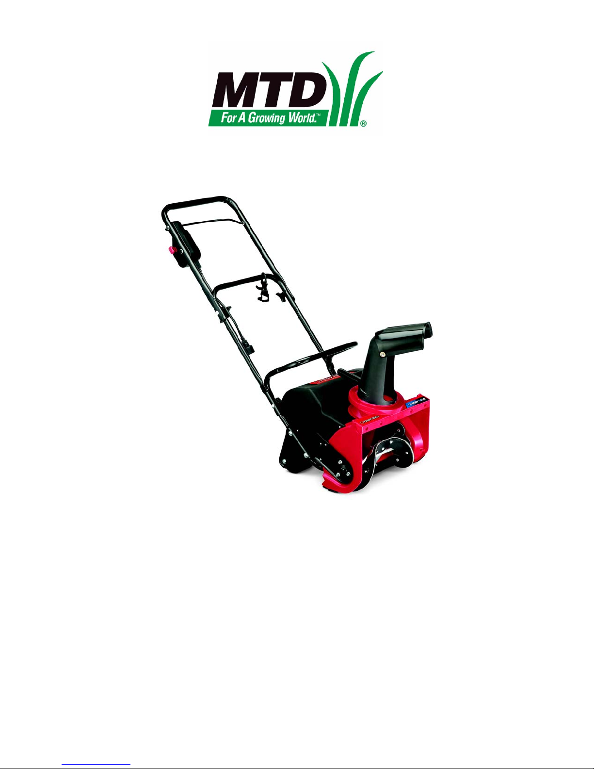
Description of the Troy-Bilt Snow Flurry
The Troy-Bilt Flurry 1400 is a compact, ele ctr ic snow
thrower that is ideal for milder winters, smaller driveways
and lighter snowfalls.
Figure 1.1
www.mymowerparts.com
3

For Parts Call 606-678-9623 or 606-561-4983
Snow Flurry 1400
Understanding model and serial numbers
The model number of a the snow thrower described in this
manual is 31A-050-711. This manual is likely to carry useful information for a range of similar snow throwers that
may carry a variety of MTD and private brand names.
Figure 1.2
The break down of what the model number
• 31 - - - - - - - - - - - - - - - - - - - - - - - - -Indicates that this is a snow thrower.
• - - A - - - - - - - - - - - - - - - - - - - - - - - -Sales level
• - - - -050 - - - - - - - - - - - - - - - - - - - - -Indicates this is a Snow Flurry
• - - - - - - - - 711- - - - - - - - - - - - - - - - -Customer number
The serial number is 1G150P00082. The serial number
• 1 - - - - - - - - - - - - - - - - - -Engineering level
• - G - - - - - - - - - - - - - - - - -Month of production (G = July)
• - - - 15- - - - - - - - - - - - - - - -Day of the month
• - - - - - 0 - - - - - - - - - - - - - - -Last digit of the year
• - - - - - - P - - - - - - - - - - - - - -Plant it was built in
• - - - - - - - - 0 - - - - - - - - - - - - -Assembly line number
• - - - - - - - - - -0082 - - - - - - - - - -Number of unit built
Additional technical and service information may also be available to our company authorized service center personnel through our company corporate offices, regional parts distributors and regional service center field support
personnel. Please contact the designated support office in your area or our corporate offices directly should further
service information be needed.
means is as follows:
reads as follows:
MTD Products LLC
P.O. Box 368022
Cleveland, OH 44136
Telephone: (800) 800-7310
www.mtdproducts.com
4
www.mymowerparts.com

For Parts Call 606-678-9623 or 606-561-4983
CHAPTER 2: ELECTRICAL
Basics of electricity
In order to diagnosis any electrical system there are few things the technician must understand:
• Basic electrical values: voltage, current and resistance
•Ohm’s law.
• Kirchhoff’s current law.
• Kirchhoff’s voltage law.
• How the system is wired together.
The first electrical value to be discussed is Voltage.
• Voltage is the “pressure” that electricity has. It is the amount of force pushing electrons through a circuit.
• This pressure is measured in volts.
Electrical
• The capital letter “V” is used to represent volts.
The second electrical value is Current:
• Current is the “flow” of electricity. It is the amount of electrons flowing in circuit.
• The flow of current is measured in Amperes or Amps for short.
• The capital letter “I” is used to represent Amps.
The third and final value is Resistance:
• Resistance is the opposition to current flow. It is a restriction that slows down the flow of current.
• Resistance is measured in Ohm’s.
• The greek letter omega “
Ohm’s law
V
Ω” or the capital letter “R” is used to represent Ohm’s.
Ohm’s law states that voltage is the product of resistance times current. It is written as V=I x R. An example of
how ohm’s law works goes like this: It takes 12 volt to push
2 amp through a resistance of 6 ohm (12=2 x 6). Ohm’s
law can be drawn in a triangle. When using the triangle,
cover the value to be found, and the two values left
exposed signify how to obtain that value. See Figure 2.1.
I
Figure 2.1
R
www.mymowerparts.com
As an example if the “R” is covered, the “V” is over the
“I” which means V is divided by I. If the “V” is covered, “I”
and “R” is exposed, meaning IxR and so on.
5
For Parts Call 606-678-9623 or 606-561-4983
Snow Flurry 1400
Kirchhoff’s current law
Kirchhoff’s current law deals with nodes. Nodes are
the junction of two or more wires or the junction of a wire to
a component. Kirchhoff’s current law st ates that what ever
current goes into a node must come out.
As an example: Three wires are connected with a wire
nut. one wire has 5 amps going into th e wire nut. Th e sum
of the current coming out of the other two wires mu st equal
5 amps. That could be 3 amps in one wire and 2 amps in
the other or it could be 2.5 amps in each wire, but the total
must be the same as the current coming in.
See Figure 2.2.
Kirchhoff’s voltage law
Kirchhoff’s voltage law deals with volta ge drops. A voltage drop is the amount of voltage used up or “dropped” by a
resistance in the circuit. Ohm’s law stated that V = IxR, every component in a circuit has resistance, even the wires.
To push current through a re sistance, it takes voltage. Kirchhoff’s voltage law states that the sum of all the voltage
drops equals the source voltage.
5 Amps
Node
3 Amps
2 Amps
Figure 2.2
An example: a circuit has a battery of 12V, a light bulb that creates 3 ohms of resistance and there is 4 amps of current in the circuit. The wires are assumed to have 0 ohms, if the proper size wir e is used and ther e is no co rrosion in
the wire, the resistance will be too small to worry about. The light bulb uses 12 volts (4 amps x 3 ohms = 12 volts).
The battery has 12 volts that equals the 12 volts used by the light bulb.
AC electricity
AC electricity is used to provide electricity to homes
and businesses because it can be easily transmitted over
long distances. Some household products can run on
straight AC power while most will convert it to a usable DC
form internally.
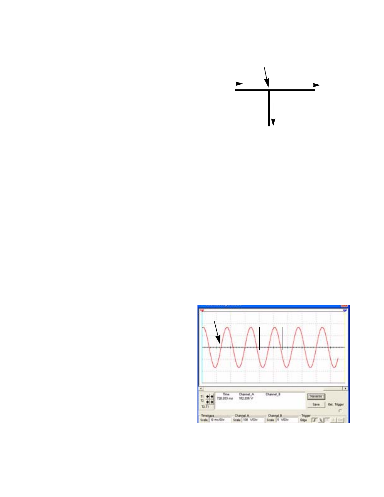
AC or alternating current is a current or voltage value
that varies with time and has an average value of zero. If
the current or voltage is observed using an oscilloscope,
the waveform will look like a sine wave. This means it will
be positive for awhile then it will be negative for awhile.
The time spent positive will equal the time spent negative.
Since it spends just as much time positive as negative, the
positive values cancel out the negative values leaving an
average value of zero. See Figure 2.3.
Since AC varies with time, the time or phase angle of
the waveform is needed to compute voltage and current.
This manual will not go into how to do this. AC is only mentioned here as a reference.
AC wave form
1 Cycle
Figure 2.3
+
-
6
www.mymowerparts.com
For Parts Call 606-678-9623 or 606-561-4983
Electrical
Electric circuits
All circuits have some basic rules that must be followed:
1. All circuits must have at least one voltage source. It could be a battery, an alternator or both.
2. All circuits must have a load. To make a circuit without a load is the same as shorting out the power source. A
load could be:
•a lamp
•a motor
• a resistor
• a starter
3. All circuits must have a complete path back to the voltage source. This is also known as having continuity.
4. Most circuits have additional components like switches and fuses.
Types of circuits
There are three ways a circuit can be wired. They are:
•Series
• Parallel
• Series/parallel
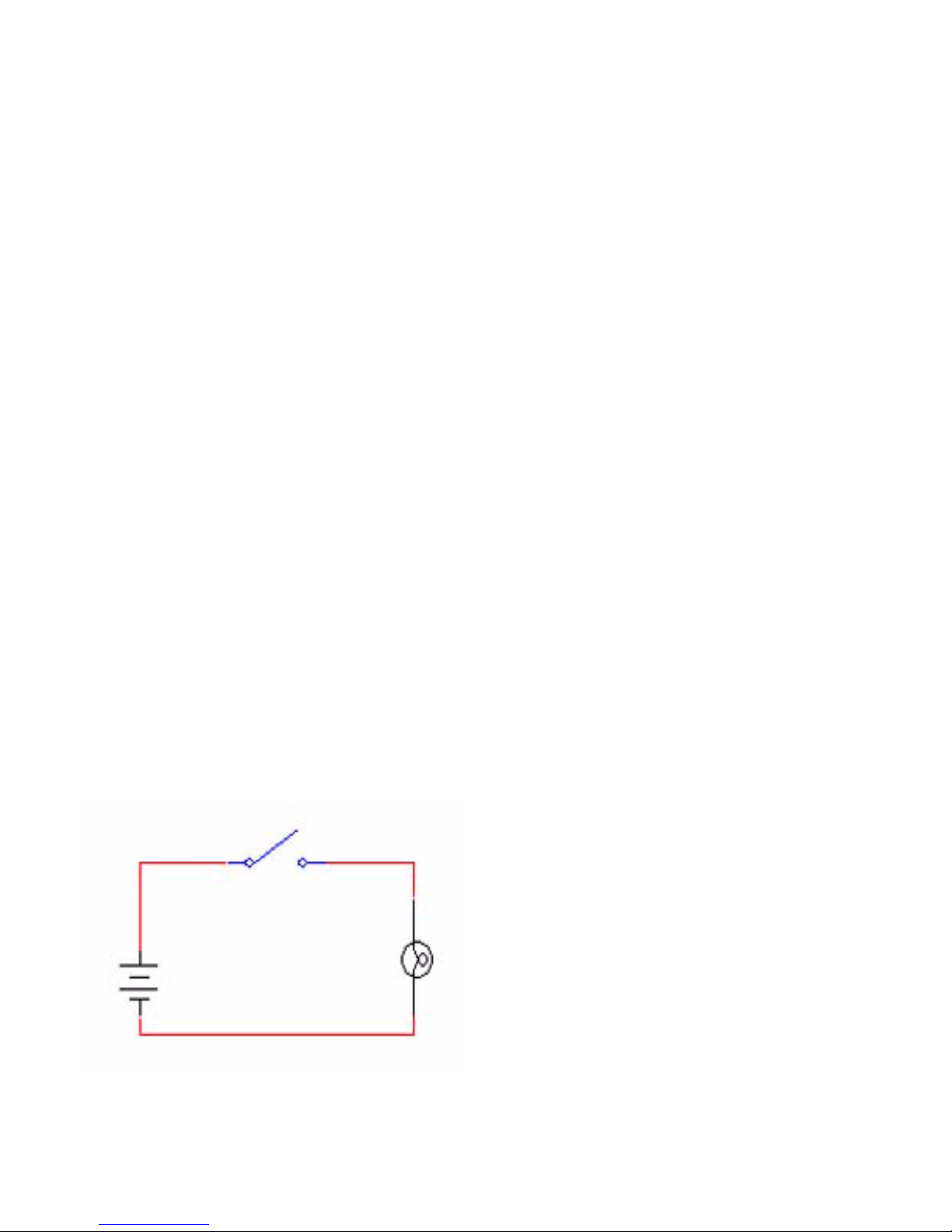
Series
Switch
Bulb
Battery
Figure 2.4
• Series circuits are wired so that the current has
only one path to follow. See Figure 2.4.
www.mymowerparts.com
7
For Parts Call 606-678-9623 or 606-561-4983
Snow Flurry 1400
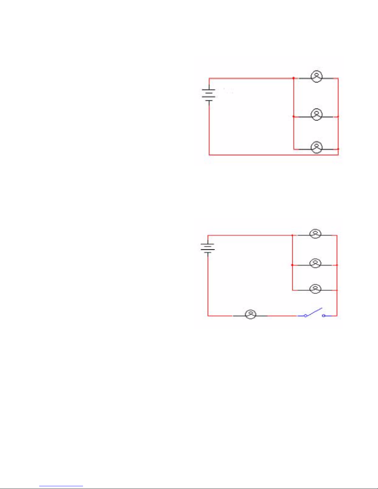
Parallel
• Parallel circuits are wired so that current has
multiple paths to follow. See Figure 2.5.
Figure 2.5
Series/parallel
• Series/parallel circuits have some sections
wired in series and some in parallel.
See Figure 2.6.
Figure 2.6
8
www.mymowerparts.com

For Parts Call 606-678-9623 or 606-561-4983
Circuit failures
There are three types of failures that can occur in an electrical circuit:
1. Shorts
2. Opens
3. Increased resistance
Shorts
A short is when electricity takes a path that it was not designed to take bypassing a component in the circuit.
A common example of a short is the wire that chafed through. The bare copper will short the circuit when it
touches a ground source.
Opens
An open is when current can not complete its path back to the power source.
A common example of this is a blown fuse.
Increased resistance
Increased resistance is as the name implies, an increase in resistance.
Electrical
Arguably the most common electrical failure, and the hardest to find, is when there is a loose connection or corrosion. It is not an open because there is some current that can get through, but the increase in resist ance is enough
to affect the circuit
Tools
• Digital volt ohm meter
• Wiring or a schematic diagram.
Equipment that may be useful:
• Fused jumper wires.
• Hand tools to gain access to components.
• Flash light.
www.mymowerparts.com
9
For Parts Call 606-678-9623 or 606-561-4983
Snow Flurry 1400
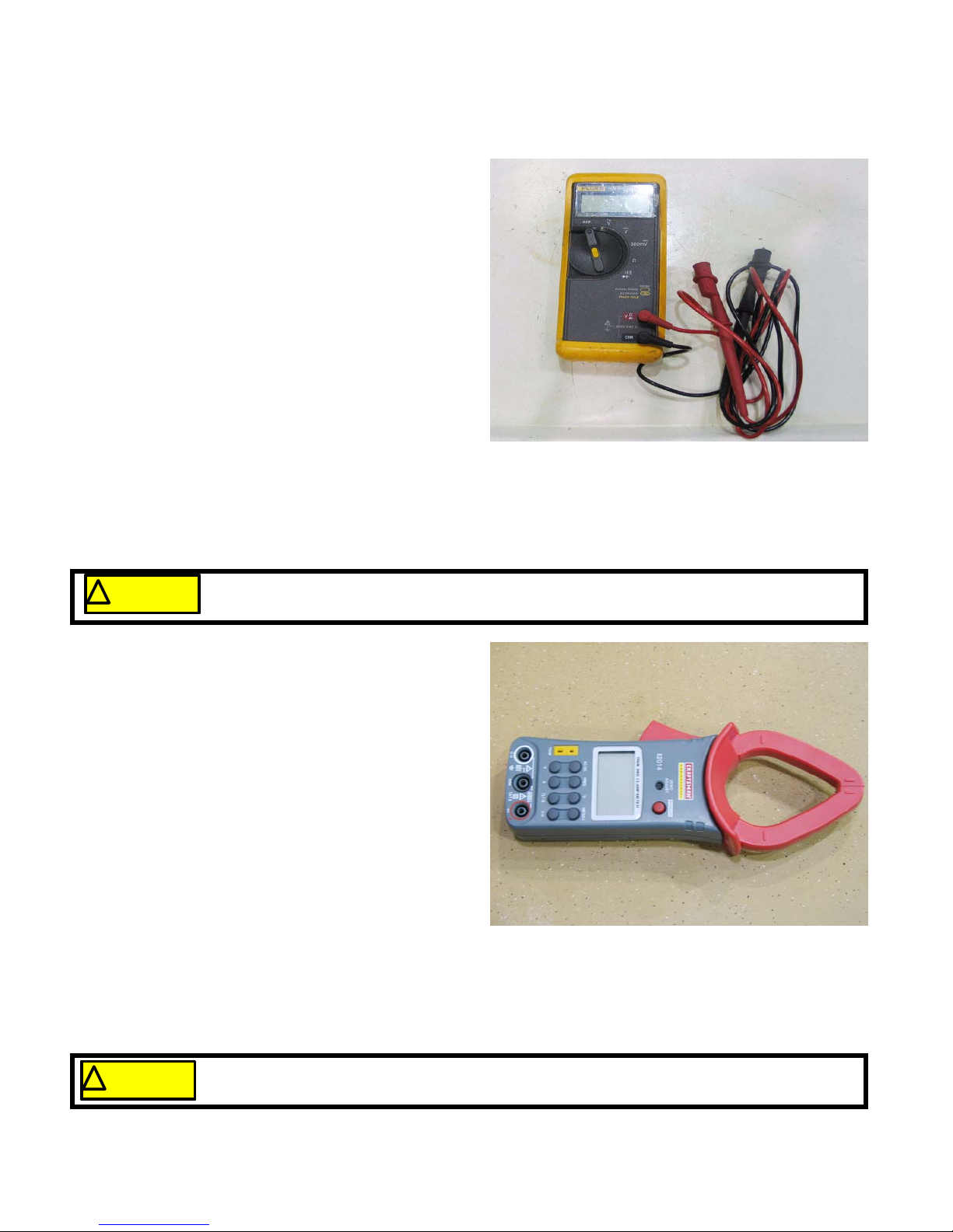
Digital multimeter
Digital Multi Meters or DMMs are the most useful tool
to trouble shoot any electrical system. Depending on the
model of DMM used, DMMs can measure Volts, Amps,
Ohms and more. DMMs are a must when working on circuits with solid state components (microchips). They have
very high impedance, that means they have very high
resistance and pull very little current from the circuit. Use
of analog equipment or test lights will pull enough current
to damage the microchips in the circuit. See Figure 2.7.
When measuring volts, always hook the meter in parallel with the circuit. That means do not disconnect the
component where measuring voltage.
When measuring current, the meter must be connected in series with the component to be measured. That
means opening the circuit and having the circuit go
through the meter.
NOTE: When measuring current, exceeding the
meters rating will damage the meter.
Figure 2.7
NOTE: The only exception to this is when using an inductive amp clamp.
NOTE: When measuring resistance, the component must be isolated from the circuit.
! CAUTION! CAUTION
Inductive amp meter
An inductive amp meter, sometimes referred to as an
“amp clamp” or clamp meter, measures current following
through a wire by the magnetic field created around the
wire. Clamp meters are very important when dealing with
currents over 10 amps. A DMM typically can not measure
current over 10 amps. Clamp meters are also helpful
because they can read current in a circuit without opening
it up to hook the meter into the circuit. See Figure 2.8.
Wiring or a schematic diagram
A wiring or a schematic diagram is very important in
troubleshooting a circuit. The diagram shows how the circuit was designed and what paths the electricity is suppose to flow.
The meter has its own power source to measure resistance. Conn ecting the meter to a component that has current going through it will damage the meter (usually beyond repair).
Figure 2.8
Fused jumper wires
Fused jumper wires are handy to help find bad grounds or to jump across switches for testing purposes.
! CA UTION! CA UTION
10
Only use fused jumper wires. If there is a short in the circuit, using an unfused jump could damage components in the circuit further.
www.mymowerparts.com
 Loading...