

Page 1
$7.50
Owner/Operator
Manual
ECONO·HORSETM
PONY
Model
- Safety
- Assembly
- Controls
- Operation
-
Maintenance
®&
Tillers
JUNIOR
®
Page 2

TABLE
OF
CONTENTS
SECTION 1: SAFETY INSTRUCTIONS .4
Safety Alert Symbol .4
Training .4
Preparation .4
Operation .4
Maintenance and Storage 6
Decals 6
SECTION 2: EASY ASSEMBLY 7
SECTION 3: TILLER AND
ENGINE
Tiller Controls 18
Engine Controls 22
SECTIO N 4: OPERATION OF TILLER 24
Be
To Begin Tilling 25
Turning Around 25
Stopping the Tiller and Engine 25
Changing Speeds (Econo-Horss only) 26
Tilling in the Garden 27
CONTROLS
Wheel Gear Lever (Econo-Horse
Wheel Drive Pins (Junior only) 19
Forw
ard
Clutch 20
Maneuvering Clutch 20
Depth Regulator 21
Handlebar Height Adjustment 21
Starting Your Engine 22
Starting the Electric Start Engine
With the Recoil Starter Rope 23
Stopping the Engine 23
for
e Starting 25
Change
To
To Change from HIGH Speed to LOW 27
Guiding Your Tiller. 27
Tilling Depths 27
Tilling Patterns 28
Choosing Wheel and Tine Speeds 29
Avoid Making Footprints 29
Clearing Debris from the Tine Area 29
Power
Use Reverse to Turn in Tight Areas 30
Tilling Near Obstacles 30
Tilling Up and Down Slopes 31
Tilling Across Slopes Using Terraces 31
Tilling Across Slopes Without Terraces 32
Loading and Unloading the Tiller 32
from LOW Speed to HIGH 26
Comp
osting 30
& Pony) 18
18
SECTION 5: TILLER AND
ENGINE MAINTEN ANCE.
Lubrication , 33
Check for Oil Leaks 34
Tightening Nuts and Bolts , 34
Checking, Adding or Chang ing
Gear
Transmission
To Check the Transmission
Gear Oil Level 34
To Add Gear Oil to the
Transmission 35
To Drain and Refill the
Transmission 35
Checking Engine Oil Level 35
Changing Engine Oil 36
Air Cleaner Service 36
Spark Plug Maintenance 37
Ignition System Maintenance 37
Air Cooling System Maintenance 37
Bolo Tines 37
Removing Bolo Tine Assemblies 38
Removing Individu al Bolo Tines 38
Checking Tension on the Drive Belts 38
Forward Drive Belt Tension 39
Reverse Drive Belt Tension 39
Adjusting Forward Drive Belt Tension 39
Removing Forward Drive Bel
Installing Forward Drive Belt .. .41
Removing Reverse Drive Belt.. .42
Installing Reverse Drive
Adjusting Reverse Drive Belt Tension .43
Wheel Gear Cable Adjustment .43
Engine Throttle Cable Adjustment .44
Off-Season Storage .44
Troubleshoot Electric Start System .45
Starter Motor Won't
Ignition Switch Doesn't Stop Engine 46
Battery Care and Maintenance .47
Care in Service .47
Battery Storage .47
Carburetor Adjustment .47
Specifications .48
Recommended Maintenance Intervals .49
INDEX REFERENCE 52
Oil 34
t..
BelL
Turn Over .45
33
.41
.42
Page 3
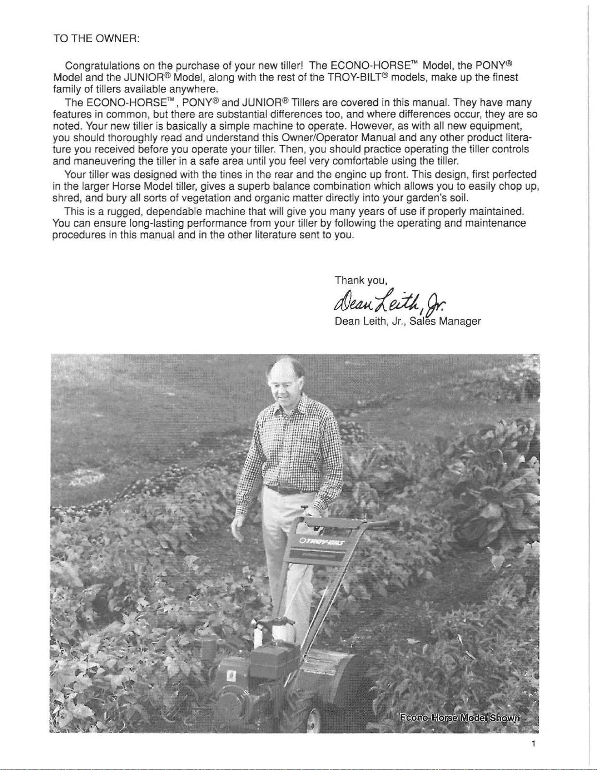
TO THE OWNER:
Congratulations on the purchase of your new tiller! The ECONO-HORSE'" Model, the PONY®
Model and the JUNIOR ® Model, along with the rest of the TROY-BILT®models, make up the finest
family of tillers available anywhere.
The ECONO-HORSE'" , PONY® and JUNIOR®Tillers are covered in this manual. They have many
features in common, but there are substant ial differences too, and where differences occur, they are so
noted. Your new tiller is basically a simple machine to operate. However, as with all new equipment,
you should thoroughly read and understand this Owner/Operator Manual and any other product literature you received before you operate your tiller. Then,you should practice operating the tiller controls
and maneuvering the tiller in a safe area until you feel very comfortable using the tiller.
Your tiller was designed with the tines in the rear and the engine up front. This design, first perfected
in the larger Horse Model tiller, gives a superb balance combination which allows you to easily chop up,
shred, and bury all sorts of vegetation and organic matter directly into your garden's soil.
This is a rugged, dependable machine that will give you many years of use if properly maintained.
You can ensure long-lasting performance from your tiller by following the operating and maintenance
procedures in this manual and in the other literature sent to you.
Thank you,
afJ
UK
'/
edJ.
Dean Leith, Jr., Sales Manager
,
~
Page 4
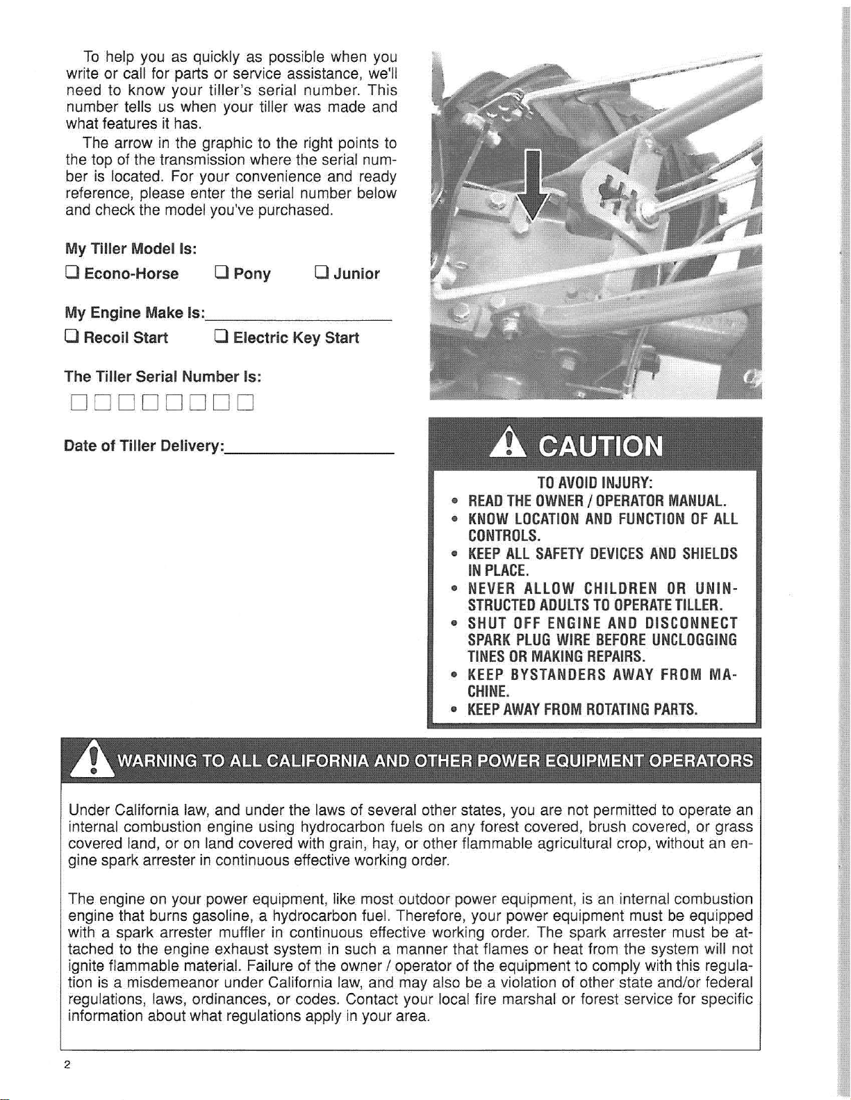
To help you as quickly as possible when you
write or call for parts or service assistance, we'll
need to know your tiller's serial number. This
number tells us when your tiller was made and
what features it has.
The arrow in the graphic to the right points to
the top of the transmission where the serial number is located. For your convenience and ready
reference, please enter the serial number below
and check the model you've purchased.
My Tiller Model Is:
o Econo-Horse 0 Pony
My Engine Make Is: _
o Junior
o Recoil Start 0 Electric Key Start
The Tiller Serial Number Is:
00000000
D
eli
ver
Date of Tiller
y:,
_
A CAUTION
TO
AVOID
•
READ
THE
OWNER/DPERATOR
•
KNOW
CONTROLS.
•
KEEPALL
IN
•
NEVERALLOWCHILOREN
STRUCTED
•
SHUT
SPARK
TINESOR
•
KEEP
CHINE
KEEP
•
LOCATION
SAFETY
PLACE.
ADULTSTOOPERATE
OFF
ENGINE
PLUG
MAKING
BYSTANDERS
.
AWAY
FROM
WIRE
INJURY:
AND
DEVICES
AND
BEFORE
REPAIRS.
ROTATING
FUNCT
AWAY
IONOFALL
ANO
ORUNIN-
DISCONNECT
UNCLOGGING
FROM
PART
MANUAL.
SHIELDS
TILLER.
MA·
S.
AWARNING TO ALL CALIFORNIA AND OTHER POWER EQUIPMENT OPERATORS
Under California law, and under the laws of several other states, you are not permitted to operate an
internal combustion engine using hydrocarbon fuels on any forest covered, brush covered, or grass
covered land, or on land covered with grain, hay, or other flammable agricultural crop, without an engine spark arrester in continuous effective working orde
The engine on your power equipment, like most outdoor power equipment, is an internal combustion
engine that burns gasoline, a hydrocarbon fuel. Therefore, your power equipment must be equipped
with a spark arrester muffler in continuous effective working order. The spark arrester must be attached to the engine exhaust system in such a manner that flames or heat from the system will not
ignite flammable material. Failure of the owner / operator of the equipment to comply with this regulation is a misdemeanor under California law, and may also be a violation of other state and/or fe
regulations, laws, ordinances, or codes. Contact your local fire marshal or forest service for specific
information about what regulations apply in your area.
2
r.
der
al
Page 5
ENGINE SERVICE
If your tiller engine ever needs service or repair, contact your nearest Briggs
Tecumseh Service Dealer.
To find the nearest Service Dealer, look in the
Yell ow
"Engines- Gasoline", or "Gasoline Engines."
If you have problems getting engine service or
parts locally, let us know so we can provide you
with the name of the nearest Service Dealer.
Page
s of your ph one
& Stratton or
book
under
QUESTIONS OR PROBLEMS?
1. Check
The answer to your question or problem may be
in this Manual. Refer to the index at the back of
this Manual to find the listing that concerns your
problem. Turn to that page and read the information provided.
this
OwnerlOperator Manual:
For Fa
In the U.S.A.:
Technical Service 1-800-833-6990
Parts Orders 1-800-648-6776
Customer Service 1·800-437-8686
In Canada:
Local only (416 Area Code) 624-8423
From Ontario and Quebec 1-800-387-3351
From Western Canada
st
est Service, Use The Toll-Free Numbers Below
& the Maritimes 1-800-387-3316
2. Call or write to us:
If you can't find the answer to your question or
problem in this Manual, please call us or write to
us. One of our helpful, friendly tiller experts will
gladly help you. Be sure to include your tiller
model name and the serial number of your tiller.
3. If you need a part:
Call or write to our Parts Department (see the
Toll-Free telephone number below). Please have
your tiller model name and serial number at
hand. Use the Parts Catalog to find the part
number
Remember that you can purchase many of the
common hardware items at your local hardware
store as well as ordering them from us.
and quantity of the part you need.
Our H
In the U.S.A. InCanada
Mon - Fri.- 8 A.M. to 7 P.M. Mon - Fr
Saturday- 9 A.M. to 4 P.M.
If you w
TROY-BILTMfg. Co. Garden Way Canada, Inc.
102nd S
Troy, New York 12180 Mississauga. Ontario L4W 2P5
IF YOU NOTICE any freight damage or missing parts, either at the time of delivery or later during
assembly, make sure that you put it in writing, within 15 days, and send your letter to the shipper
to confirm that you intend to file a claim.Tell thedriver, or inform the truck terminal, that you intend
to file a written claim. They will advise you as to how to proceed. HOWEVER, if you have any
problems with this procedure, please call us so that we can help you get satisfaction.
ould
In the U.S.A. In Canada
our
s are (Eastern Standard Time):
rather
1.
& 9th Ave. 1
writ
e to us, our mailing addresses are:
IMPOR
i-
8 A.M. to 5 P.M.
51
5 Matheson Blvd.•Unit B11
TANT!
3
Page 6
Section
1:
Safety
Instructions
Your TROY-BILT Model Tiller has been designed w
anyother piece of powered equipment, the operator
rso
times. Failure to do so could result in pe
Before assembling , operating or
the
of
O
please call us'at one of the numbers listed on page 3 of this manual.
lows the Safety Instructions. Always use
safety instructions found in this Owner / Operator Manual, in the separate Engine
wner's
If you ever lend yo
Manual, and in any ot
ur
tiller
to so meone, make sure that he or she reads, understands, and
her
servicing
literature
nal
the
you
your
tiller carefully and keep safety in mind.
ith
many safety features. However, as w
mustfollow
injury
or damagetothe
tiller
or its engine, care
may receive. If
safe operating practices at all
you
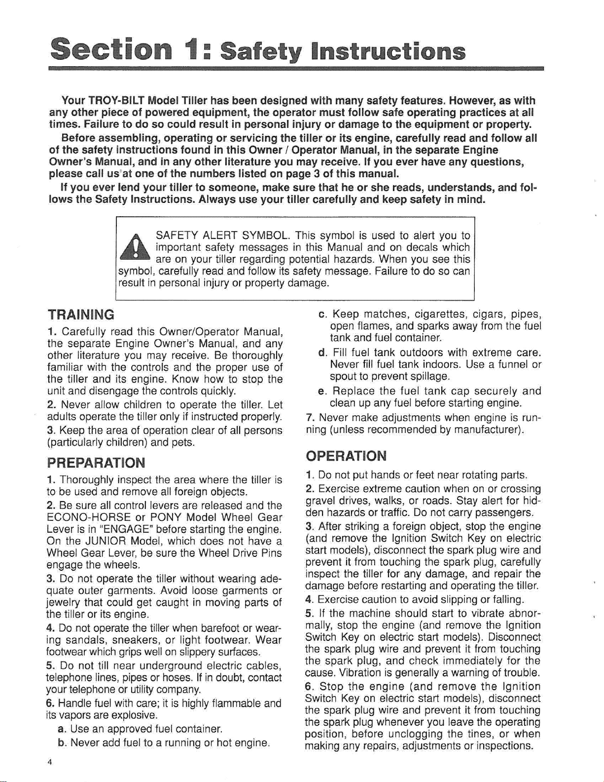
A SAFETY ALERT SYMBOL. This symbol is used to alert you to
..
symbol, carefully read and follow its safety message. Failure to do so can
result in personal injury or property damage.
TRAINI NG
1. Carefully read this Owner/Operator Manual,
the separate Engine Owner's Manual, and any
other literature you may receive. Be thoroughly
familiar with the controls and the proper use of
the tiller and its engine. Know how to stop the
unit and disengage the controls quickly.
2. Never allow children to operate the tiller. Let
adults operate the tiller only if instructed properly.
3. Keep the area of operation clear of all persons
(particularly children) and pets.
PREPARATION
1. Thoroughly inspect the area where the tiller is
to be used and remove all foreign objects.
2. Be sure all control levers are released and the
ECONO-HORSE or PONY Model Wheel Gear
Lever is in "ENGAGE" before starting the engine.
On the JUNIOR Model, which does not have a
Wheel Gear Lever, be sure the Wheel Drive Pins
engage the wheels.
3. Do not operate the tiller without wearing ade-
quate outer garments. Avoid loose garments or
jewelry that could get caught in moving parts of
the tiller or its engine.
4. Do not operate the tillerwhen barefoot or wear-
ing sandals, sneakers , or light footwear. Wear
footwearwhichgripswell on slipperysurfaces.
5. Do not till near underground electric cables,
telephone lines,pipesor hoses. If in doubt,contact
yourtelephoneor utility company.
6. Handlefuel with care; it is highly flammable and
itsvapors areexplosive.
a. Use an approved fuel container.
b. Never add fuel to a running or hot engine.
4
important safety messages in this Manual and on decals which
are on your tiller regarding potential hazards. When you see this
c. Keep matches, cigarettes, cigars, pipes ,
open flames, and sparks away from the fuel
tank and fuel container.
d. Fill fuel tank outdoors with extreme care.
Never fill fuel tank indoors. Use a funnel or
spout to prevent spillage.
e. Replace the fuel tank cap securely and
clean up any fuel before starting engine.
7. Never make adjustments when engine is running (unless recommended by manufacturer).
OPERATION
1. Do not put hands or feet near rotating parts.
2. Exercise extreme caution when on or crossing
gravel drives, walks, or roads. Stay alert for hidden hazards or traffic. Do not carry passengers.
3. After striking a foreign object, stop the engine
(and remove the Ignition Switch Key on electric
start models), disconnect the spark plug wire and
prevent it from touching the spark plug, carefully
inspect the tiller for any damage, and repair the
damage before restarting and operating the tille
4. Exercise caution to avoid slipping or falling.
5. If the machine should start to vibrate abnormally, stop the engine (and remove the Ignition
Switch Key on electric start models). Disconnect
the spark plug wire and prevent it from touching
the spark plug, and check immediately for the
cause.Vibration is generally a warning of trouble.
6. Stop the engine (and remove the Ignition
Switch Key on electric start models), disconnect
the spark plug wire and prevent it from touching
the spark plug whenever you leave the operating
position, before unclogging the tines, or when
making any repairs, adjustments or inspections.
equipment or property.
fully
read and fo
ever have any questions,
llow
ith
tol
all
-
r.
Page 7
7. Before leaving the tiller unattended, stop the
engine. Remove the Ignition Key on electric start
models. Disconnect the spark plug wire and prevent it from touching the spark plug. Move the
Wheel Gea r
Lever
to "ENGAGE" on EconoHorse and Pony models. On Junior models, the
Wheel Drive Pins must engage the wheels.
8. Before cleaning, repairing, or inspecting, stop
the engine, remove the Ignition Switch Key on
electric start models, and make certain all moving
parts have stopped. Disconnect the spark plug
wire and prevent it from touching the spark plug
to prevent accidental starting. On electric start
models, always remove the cable from the nega-
-)
tive side (
of the battery.
9. Always keep the flap on the tine hood down
when operating the tiller, except when using the
hiller/furrower attachment.
Neveroperate
10.
the
till
er with
out
proper
guards, plates, or other protective safety devices
in place.
the
11. Do not run
engine indoors; exhaus t
fumes are dangerous.
12. Keep children and pets away.
13. Never operate the tiller under engine power if
the Econo-Horse or Pony Wheel Gear Lever is in
"DISENGAGE" (FREEWHEEL), or if the Junior
Wheel Drive Pins do not engage the wheels. In
this position, the wheels will not hold the tiller
back and the revolving tines could propel the
tiller rapidly, possibly causing loss of control.
Always move the Wheel Gear Lever to "EN-
GAGE" (or, on the Junior, ENGAGE the wheels
with the Wheel Drive Pins) before starting the
engine or engaging the tines / wheels with the
Forward Clutch or the Maneuvering Clutch.
14. Be aware that the tiller may unexpectedly
bounce
upward
or jump forward if the t
ines
should strike extremely hardpacked soil, frozen
round
g
, or
bur
ied
obstac
les such as
large
stones, roots, or stumps. If you are in doubt
about the tilling conditions, always use the following operating precautions to assist you in
maintaining control of the tiller:
a. Walk behind and to one side of the tiller,
using one hand on the handlebars. Relax
your arm, but use a secure hand grip.
b. Use sha llower depth regulator settings,
working gradually deeper with each pass.
c. Place the forwar d drive belt in its LOW
Range position (Econo-Horse only). Use
slower engine speeds.
d. Clear the tilling area of all large stones ,
roots and other debris.
e. Avoid using downward pressure on handle-
bars. If need be, use slight upward pressure
to keep the tines from digging too deeply.
f. Before contacting hardpacked soil at the end
of a row, reduce engine speed and lift handlebars to raise tines out of the soil.
g. In
wheels
Lever
you
to restrain the
ncy,stop
by
releasing
have engaged . Do
tiller
.
thetines
and
whicheverClutch
not
attempt
an
eme
rge
15. Do not overload the tiller's capacity by attempting to till too deeply at too fast a rate.
16. Never operate the tiller at high transport
speeds on slippery surfaces. Look behind and
use care when backing up.
17. Do not operate the tiller on a slope that is too
steep for safety. When on slopes, slow down and
make sure you have good footing. Never permit
the tiller to freewheel down slopes.
18. Never allow bystanders near the unit.
19. Only use attachments and accessories that
are approved by Troy-Bilt Manufacturing Co.
20. Use tiller attachments and accessories when
recommended.
21. Never operate the tiller without good visibility
or light.
22. Neveroperate the tillerif youare tired,or under
lcohol
the influenceofa
,drugsor medication.
23. Do not change the engine governor settings or
overspeed the engine.
24. Do not touch engine parts which may be hot
from operation. Allow parts to cool before inspecting,cleaningor repairing.
25. The battery on electric start model tillers con-
tains sulfuric acid. Avoid contactwith skin, eyes, or
clothing.Keepout of the reachof children.
Antidote-Externa l Contact: Flush immediately
with lotsof water.
Antidote-Internal: Drinklarge quantitiesofwater
or milk. Followwith milk of magnesia, beaten
egg orvegetable oil. CALL A PHYSICIAN IMMEDIATELY.
Antidote-Eye Contact: Flush with water for 15
minutes. GET PROMPT MEDICAL ATTENTION.
26. Batteries produce explosive gases. Keep
spar
ks, flame , and smoking materials away.
Ventilate when charging batteries or when using a
ALWA
batteryinan enclosed space.
goggleswhenworkingnearbatte
YS wearsafety
ries.
27. Please remember: You can always stop the
tines and wheels by releasing the Forward Clutch
Lever or the Maneuvering Clutch Lever (whichever
lever you have e
Control Leverto
ngaged
STOP.
) or by moving the T
hrottle
28.Toload or unload the tiller, see the instructions
in Section 4 ofthis Manual.
5
Page 8
MAINTENANCE AND STORAGE
1. Keep the tiller, attachments and accessories
in safe working condition.
2. Check all nuts, bolts, and screws at frequent
intervals
for
proper
tightness
to be sure the
equipment is in safe working condition.
3. Never store the tiller with fuel in the fuel tank inside a building where fumes may reach an open
flame or spark (hot water and space heaters, furnaces, clothes dryers,stoves,electricmotors, etc.).
4. Allow the engineto cool before storing it.
5. Toreduce the chances of a fire hazard, keep the
engine freeof grass, leaves,or excessive grease.
6. Store gasoline in a cool, well-ventilated area,
safely away from any spark or flame-producing
equipment. Store gasoline in an approved con-
tainer, safely away from the reach of children.
7. Refer to the Tiller and Engine Maintenance
section of this Manual for instructions if the tiller is
to be stored for an extended period.
8. Never perform maintenance while the engine
is running or the spark plug wire is connected, except when specifically instructed to do so.
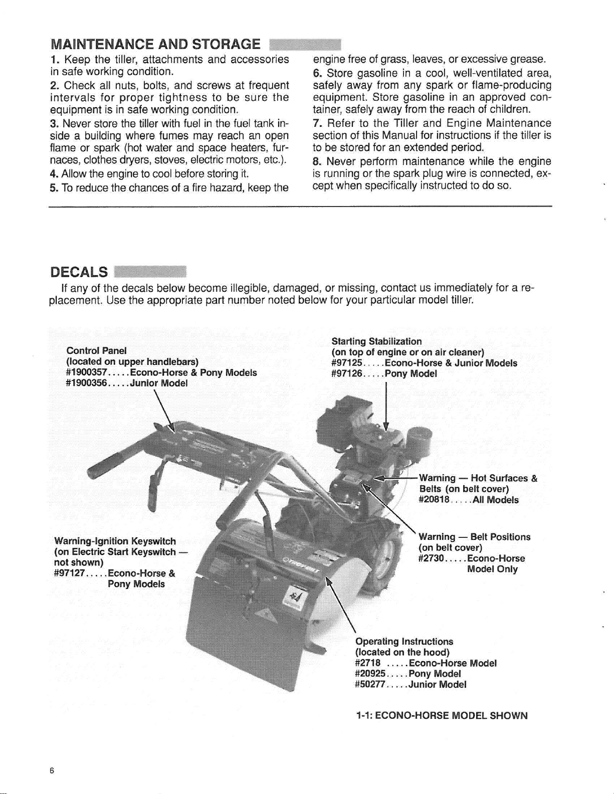
DECALS
If any of the decals below become illegible, damaged, or missing, contact us immediately for a re-
placement. Use the appropriate part number noted below for your particular model tiller.
Control
(located on
#1900357 Econo-Horse & Pony Models
#1900356 Junior Model
Warning-Ignition Keysw itch
(on Electric Start Keysw
not
shown)
#97127
Panel
upper
.....
Econo-Horse &
Pony Models
handlebars)
itch
-
Starting Stabilizat
(on top01engine or on
#97125 Econo-Horse & Jun
#97126 Pony Model
ion
air
cleaner)
,j
Warning - Hot Surfaces &
Belts (on belt cover)
#20818 .... .AII Models
Warning - Belt Positions
(on belt cover)
#2730 ... . .Eco
ior
Models
no-
Horse
Model Only
Operat
ing
Instructions
(located on the
#2718 Econo-Horse Model
#20925 Pony Model
#50277
1-1: ECONO-HORSE MODEL SHOWN
6
hood)
Junio
r Model
Page 9
Section
2:
Ea
sy
Assembly
Please
Model tiller and prepare it for use. Due to assembly similarities , we show one model in the assembly photos to represent the three tiller models. Steps unique to any single model(s) are
noted.These steps will
We recommend you read thi s Section all the way through
follow
the steps in this Section to assemble your ECONO·HORSE" , PONY" or JUNIOR®
not
take long and will assure correct assemblyofyour new tiller.
firs
t. Then begin the assemb ly steps.
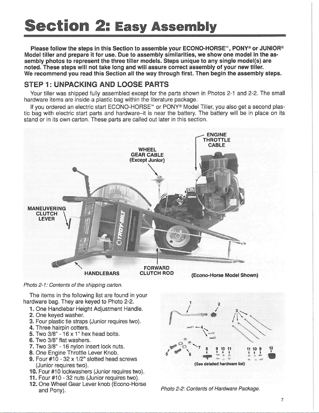
STEP 1: UNPACKING AND LOOSE PARTS
Your tiller was shipped fully assembled except for the parts shown in Photos 2-1 and 2-2. The small
hardware items are inside a plastic bag within the literature package.
If you ordered an electric start ECONO-HORSE'" or PONY®Model Tiller, you also get a second plastic bag with electric start parts and hardware- it is near the battery. The battery will be in place on its
stand or in its own carton . These parts are called out later in this section.
ENGINE
THROTTLE
WHEEL
GEAR CABLE
(Except Junior)
CABLE
-,
MANEUVERING
CLUTCH \
LEVER
Photo 2-1: Contents of the shipping carton.
The items in the following list are found in your
hardware bag. They are keyed to Photo 2-2.
1. One Handlebar Height Adjustment Handle.
2. One keyed washer.
3. Four plastic tie straps (Junior requires two).
4. Three hairpin cotters.
5. Two 3/8" - 16 x 1" hex head bolts.
6. Two 3/8" flat washers.
7. Two 3/8" - 16 nylon insert lock nuts.
8. One Engine Throttle Lever Knob.
9. Four #10 - 32 x 1/2" slotted head screws
(Junior requires two).
10. Four
11.
12. One Wheel Gear Lever knob (Econo-Horsa
#1
Four#10
and Pony).
I
HANDLEBARS
0 lockwashers (Junior requires two).
- 32 nuts (Junior requires two).
FORWARD
CLUTCH ROD
"-°0'"
/
5
Photo
(Econo-Horse Model Shown)
2
I
•
-0
- 4
•
fI'""
~
,
"'6
2-2
: Contents of Hardware Package.
'\-a
-a
7 8 9 10 11
1
' t .
-
....
(See detailed hardware list)
0"
""
0 •
11 10 9
• • I
b
0-
..
.-
12
t
•
7
Page 10
Compare the parts that you received to Photos 2-1 and 2-2. If you are missing any items, please call
us at one of the telephone numbers listed on page 3 of this Manual.
If you notice any freight damage, either at the time of delivery or later during assembly, contact the
freight terminal and tell them you will be filing a written claim (do so within 15 days). The terminal will
advise you as to how to proceed. However, if you meet any problems with this procedure, please call
us so we can provide assistance.
Before you attempt to move the tiller off the shipping carton, please install the handlebars (Step 2).
With the handlebars installed, you'll have better leverage and be more easily able to move the tiller to a
level area so you can continue the assembly.
You'll need the following tools to assemb le your tiller:
1. Two 9/16" wrenches.
2. One medium-size flat blade screwdriver.
3. One open end 3/8" wrench.*
4. Scissors (to trim the plastic ties).
5. One 7/16" wrench (electric models only).*
6. A piece of wood to tap the knobs securely on
*
the control levers.
7. Automotive-type tire pressure gauge.
8. Ruler.
9. Sturdy wood box or block 2-1/2"
-3
-1/2" high
(Junior Model only).
•
You
may
substitu
te adj
ustablewrenche
s.
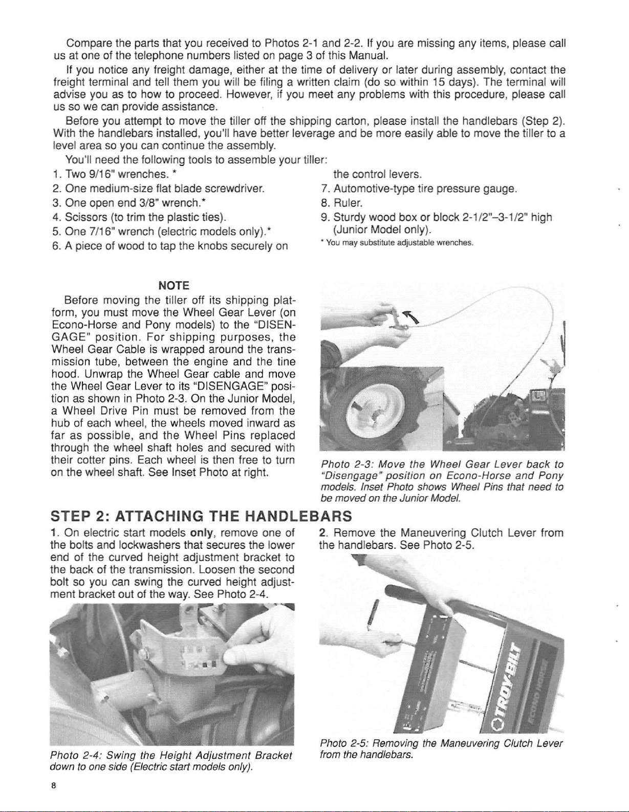
NOTE
Before moving the tiller off its shipping platform, you must move the Wheel Gear Lever (on
Econo-Horse and Pony models) to the "DISENG
AGE"position
. For shipping purposes, the
Wheel Gear Cable is wrapped around the transmission tube, between the engine and the tine
hood. Unwrap the Wheel Gear cable and move
the Wheel Gear Lever to its "DISENGAGE" position as shown in Photo 2-3. On the Junior Model,
a Wheel Drive Pin must be removed from the
hub of each wheel, the wheels moved inward as
far as possible , and the Wheel Pins replaced
through the wheel shaft holes and secured with
their cotter pins. Each wheel is then free to turn
on the wheel shaft. See Inset Photo at right.
Photo 2-3 : Move the Wheel
"Disengage"
models. Inset Photo shows Wheel Pins that need to
be moved on the Junior Model.
posit
ion on Econo-Horse
Gear
Lever
and
back
Pony
to
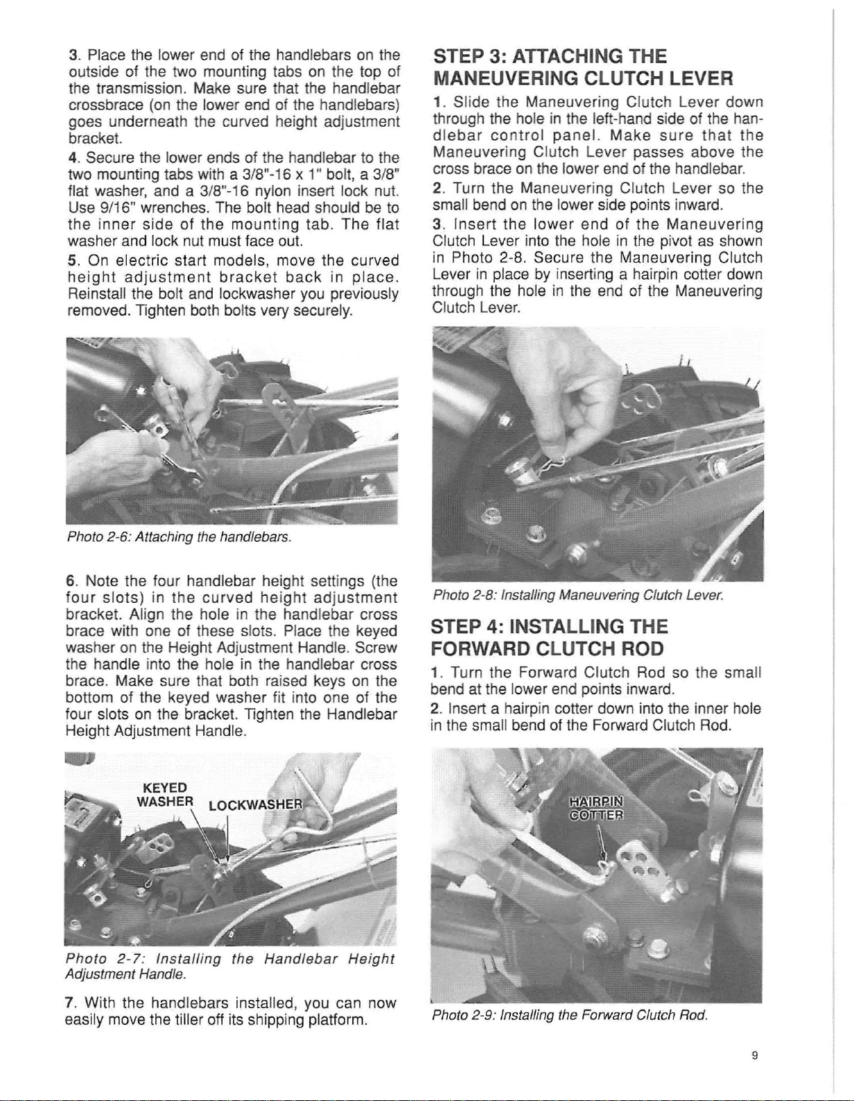
STEP 2: ATTACHING THE HANDLEBARS
1. On electric start models only, remove one of
the bolts and lockwashers that secures the lower
end of the curved height adjustment bracket to
the back of the transmission. Loosen the second
bolt so you can swing the curved height adjustment bracket out of the way. See Photo 2-4.
~
Photo 2-4: SWing the HeightAdjustm
down to one side (Electric start models only).
8
ent
Bracket
2. Remove the Maneuvering Clutch Lever from
the handlebars. See Photo 2-5.
Photo 2-5: Removing the Maneuvering Clutch Lever
from the handlebars.
Page 11
3. Place the lower end of the handlebars on the
outside of the two mounting tabs on the top of
the transmission. Make sure that the handlebar
crossbrace (on the lower end of the handlebars)
goes underneath the curved height adjustment
bracket.
4. Secure the lower ends of the handlebar to the
two mounting tabs with a 3/8"-16 x 1" bolt, a 3/8"
flat washer, and a 3/8"-16 nylon insert lock nut.
Use 9/16" wrenches. The bolt head should be to
The
the inner side of the mounting tab.
flat
washer and lock nut must face out.
5. On electric start models, move the curved
heig
ht adjustment
brac
ket
back
in pl ace.
Reinstall the bolt and lockwasher you previously
removed. Tighten both bolts very securely.
STEP 3: ATTACHING THE
MANEUVERING CLUTCH LEVER
1. Slide the Maneuvering Clutch Lever down
through the hole in the left-hand side of the handlebar
Maneuvering Clutch Lever passes above the
cross brace on the lower end of the handlebar.
2. Turn the Maneuvering Clutch Lever so the
small bend on the lower side points inward.
3. I
Clutch Lever into the hole in the pivot as shown
in Photo 2-8. Secure the Maneuvering Clutch
Lever in place by inserting a hairpin cotter down
through the hole in the end of the Maneuvering
Clutch Lever.
nsert
control
panel.Make
the lower end of the
sure
that
Maneuvering
the
Photo 2-6: Attaching the handlebars.
6. Note the four handlebar height settings (the
four
slots) in
the
curved
height ad
justment
bracket. Align the hole in the handlebar cross
brace with one of these slots. Place the keyed
washer on the Height Adjustment Handle. Screw
the handle into the hole in the handlebar cross
brace. Make sure that both raised keys on the
bottom of the keyed washer fit into one of the
four slots on the bracket. Tighten the Handlebar
Height Adjustment Handle.
Photo 2-8: Installing Maneuvering Clutch Lever.
STEP 4: INSTALLING THE
FORWARD CLUTCH ROD
1. Turn the Forward Clutch Rod so the small
bend at the lower end points inward.
2. Insert a hairpin cotter down into the inner hole
in the small bend of the Forward Clutch Rod.
Phot
o
2-7
: Insta
Adjustment Handle.
ll
ing the Ha
ndlebarHeight
7. With the handlebars installed, you can now
easily move the tiller off its shipping platform.
Photo 2-9: Installing the Forward Clutch Rod.
9
Page 12
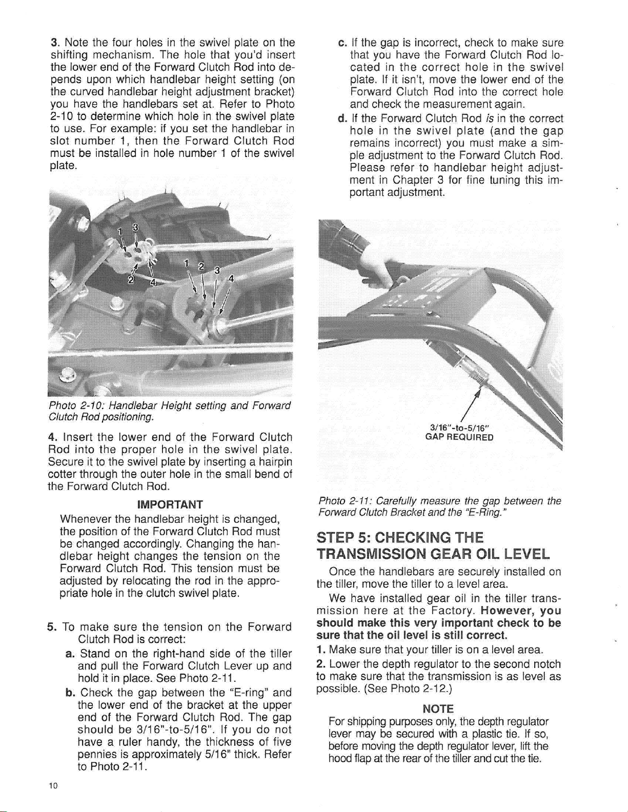
3. Note the four holes in the swivel plate on the
shifting mechanism. The hole that you'd insert
the lower end of the Forward Clutch Rod into de-
pends upon which handlebar height setting (on
the curved handlebar height adjustment bracket)
you have the handlebars set at. Refer to Photo
2-10 to determine which hole in the swivel plate
to use. For example: if you set the handlebar in
slot number 1, then the Forward Clutch Rod
must be installed in hole number 1 of the swivel
plate.
c. If the gap is incorrect, check to make sure
that you have the Forward Clutch Rod located in the correct hole in the swivel
plate. If it isn't, move the lower end of the
Forward Clutch Rod into the correct hole
and check the measurement again.
d. If the Forward Clutch Rod is in the correct
hole in
swivel
plate
(and
the
gap
the
remains incorrect) you must make a simple adjustment to the Forward Clutch Rod.
Please refer to handlebar height adjustment in Chapter 3 for fine tuning this important adjustment.
Photo 2-10: Handlebar Height setting
Clutch Rod positioning.
and
Forward
4. Insert the lower end of the Forward Clutch
Rod into the proper hole in the swivel plate.
Secure it to the swivel plate by inserting a hairpin
cotter through the outer hole in the small bend of
the Forward Clutch Rod.
IMPORTANT
Whenever the handlebar height is changed,
the position of the Forward Clutch Rod must
be changed accordingly. Changing the handlebar height changes the tension on the
Forward Clutch Rod. This tension must be
adjusted by relocating the rod in the appropriate hole in the clutch swivel plate.
5. To make sure the tension on the Forward
Clutch Rod is correct:
a. Stand on the right-hand side of the tiller
and pull the Forward Clutch Lever up and
hold it in place. See Photo 2
-11.
b. Check the gap between the "E-ring" and
the lower end of the bracket at the upper
end of the Forward Clutch Rod. The gap
should be 3/16"-to-5/16". If you do not
have a ruler handy, the thickness of five
pennies is approximately 5/16" thick. Refer
to Photo 2-11.
3/16" -10-5/16"
GAP REQUIRED
Photo 2-11: Carefully measure the gap between the
Forward Clutch
Bracket and the "E-Ring."
STEP 5: CHECKING THE
TRANSMISSION GEAR OIL LEVEL
Once the handlebars are securely installed on
the tiller, move the tiller to a level area.
We have installed gear oil in the tiller transmission here at the
shou
ld make t
his
Factory
very important checkto be
sure that the oil level is sti ll correct.
1. Make sure that your tiller is on a level area.
2. Lower the depth regulator to the second notch
to make sure that the transmission is as level as
possible. (See Photo 2-12.)
NOTE
For
shipping
purposes
only, the
lever may be secured with a plastic tie. If so,
before
moving
the
depth
hoodflapattherearofthetillerandcutthetie.
. However,you
depth
reguiator
lever,
regulator
liftthe
10
Page 13
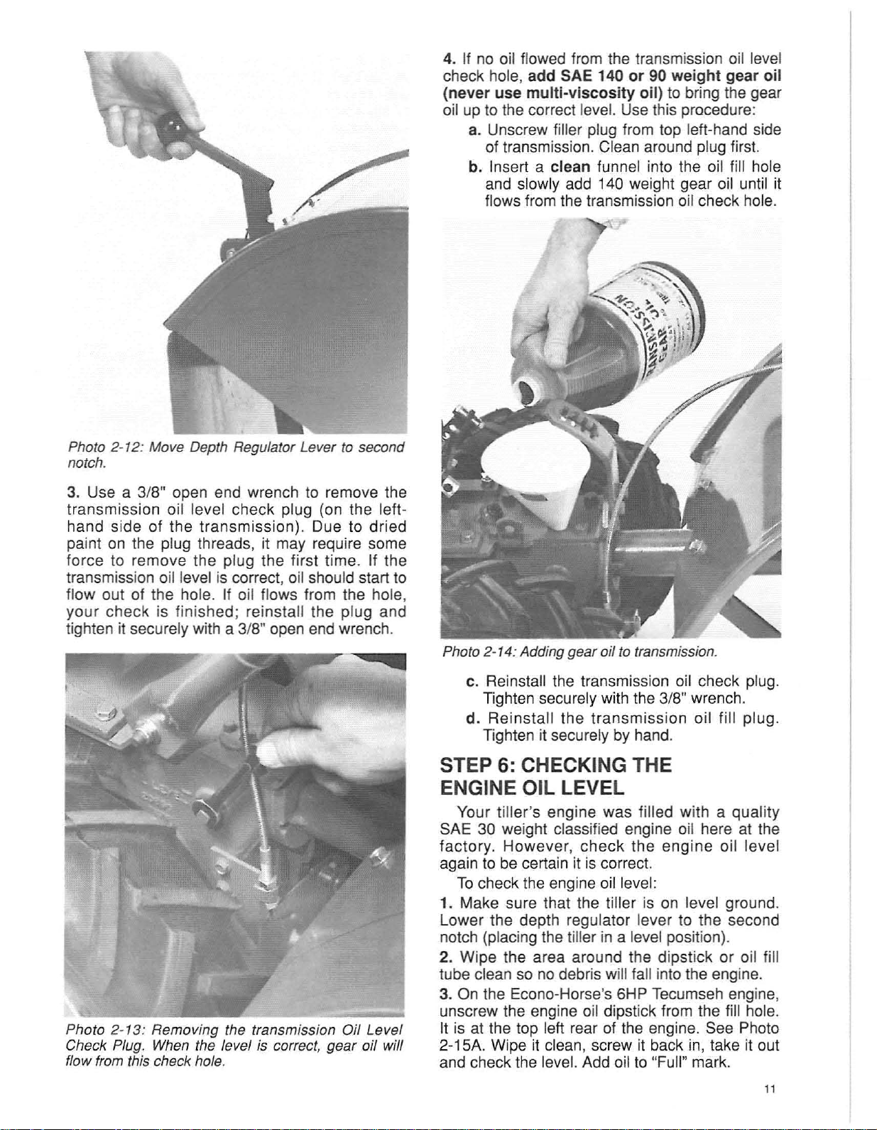
Photo 2-12: Move Depth Regulator Lever to second
notch.
4. If no oil flowed from the transmission oil level
igh
check hole, add SAE 140 or 90 we
(never use multi-v
iscosity
oil) to bring the gear
t gear oil
oil up to the correct level. Use this procedure:
a. Unscrew filler plug from top left-hand side
of transmission. Clean around plug first.
b. Insert a clean funnel into the oil fill hole
and slowly add 140 weight gear oil until it
flows from the transmission oil check hole.
3. Use a 3/8" open end wrench to remove the
transmission oil level check plug (on the lefthand side of the transmiss ion). Due to dried
paint on the plug threads, it may require some
force to remove the plug the first time. If the
transmission oil level is correct, oil should start to
flow out of the hole. If oil flows from the hole,
your check is finished; reinstall the plug and
tighten it securely with a 3/8" open end wrench.
Photo 2- 13: Removing the transmis sion Oil Level
Check Plug. When the level
flow from this check hole.
is correct, gear oil will
Photo 2-14:
Add
ing gear oil to transmission.
c. Reinstall the transmission oil check plug.
Tighten securely with the 3/8" wrench.
d. Reinstall the transmission oil fill plug.
Tighten it securely by hand.
STEP 6: CHECKING THE
ENGINE OIL LEVEL
Your till
SAE 30 weight classified engine oil here at the
factory. However, check the engine oil level
again to be certain it is correct.
Tocheck the engine oil level:
1. Make sure that the tiller is on level ground.
Lower the depth regulator lever to the second
notch (placing the tiller in a level position).
2. Wipe the area around the dipstick or oil fill
tube clean so no debris will fall into the engine.
3. On the Econo-Horse's 6HP Tecumseh engine,
unscrew the engine oil dipstick from the fill hole.
II is at the top left rear of the engine. See Photo
2-15A. Wipe it clean, screw it back in, take it out
and check the level. Add oil to "Full" mark.
er'
s engine was filled with a quality
11
Page 14
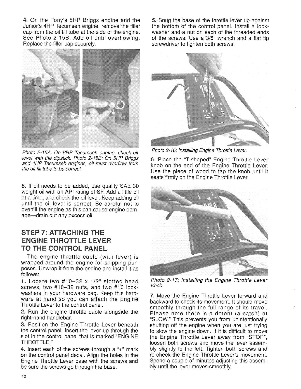
4. On the Pony's 5HP Briggs engine and the
Junior's 4HP Tecumseh engine, remove the filler
cap from the oil fill tube at the side of the engine.
See Photo 2-15B. Add oil unti l overflowing.
Replace the filler cap securely.
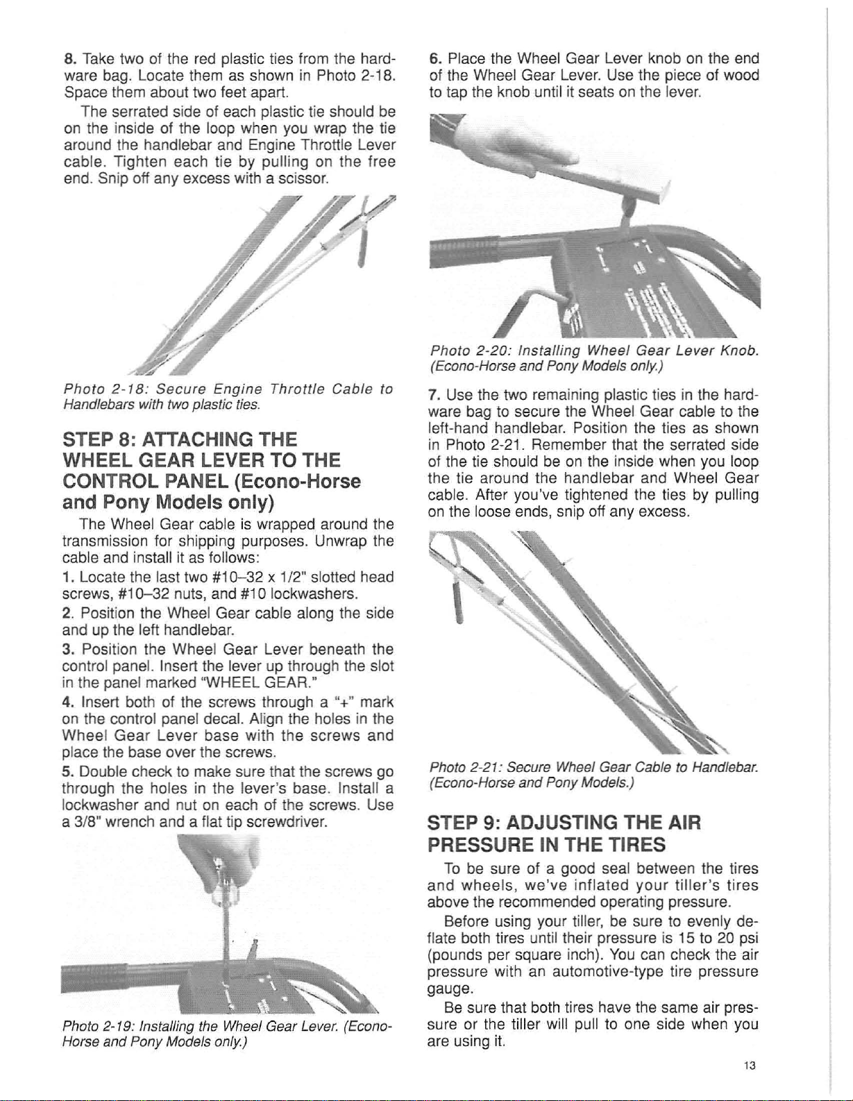
5. Snug the base of the throttle lever up against
the bottom of the control panel. Install a lockwasher and a nut on each of the threaded ends
of the screws. Use a 3/8" wrench and a flat tip
screwdriver to tighten both screws.
Photo 2-15A: On 6HP Tecumseh engine, check oil
level with the dipstick. Photo 2-15B: On 5HP Briggs
and 4HP Tecumseh engines, oil must overflow from
the oil fill tube to be correct.
5. If oil needs to be added, use quality SAE 30
SF.
weight oil with an API rating of
Add a little oil
at a time, and check the oil level. Keep adding oil
until the oil level is cor rect. Be careful not to
overfill the engine as this can cause engine damage-drain
out any excess oil.
STEP 7: ATTACHING THE
TT
ENGINE THRO
LE LEVER
TO THE CONTROL PANEL
The
engine
wrapped around the engine for shipping purposes. Unwrap it from the engine and install it as
follows:
Locate
1.
screws, two
washers in your hardware bag. Keep this hardware at hand so you can attach the Engine
Throttle Lever to the control panel.
2. Run the engine throttle cable alongside the
right-hand handlebar.
3. Position the Engine Throttle Lever beneath
the control panel. Insert the lever up through the
slot in the control panel that is marked "ENGINE
THROTTLE."
4. Insert each of the screws through a
on the control panel decal. Align the holes in the
Engine Throttle Lever base with the screws and
be sure the screws go through the base.
two
#10-32
throttle
#10-32
cable
x 1
/2"
(with
slotted
lever)
head
is
nuts, and two #10 lock-
"+" mark
Photo 2-16: Installing Engine Throttle Lever.
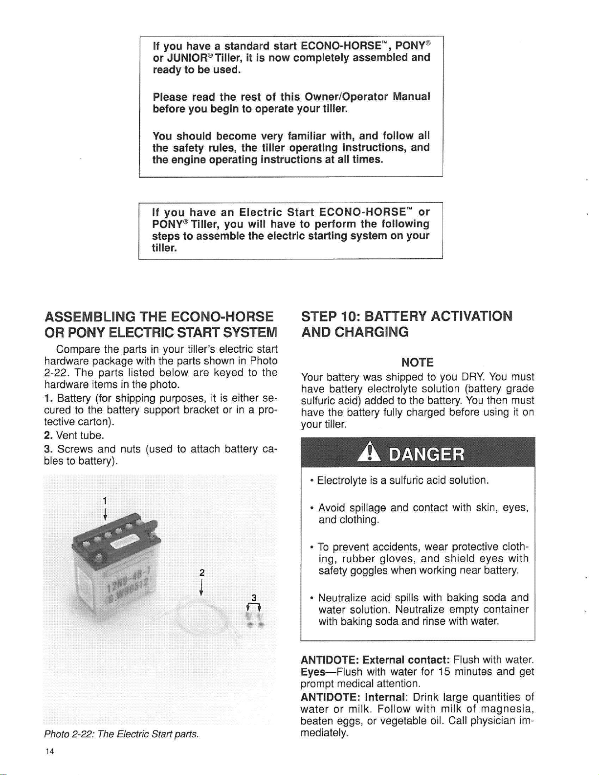
6. Place the "T-shaped" Engine Throttle Lever
knob on the end of the Engine Throttle Lever.
Use the piece of wood to tap the knob until it
seats firmly on the Engine Throttle Lever.
Photo 2
Knob.
-17
: Installing the Engine Throttle
Lever
7. Move the Engine Throttle Lever forward and
backward to check its movement. It should move
smoothly through the full range of its travel.
lease
P
note
there
is a
detent
(a
catch)
at
"SLOW." This prevents you from unintentionally
shutting off the engine when you are just trying
to slow the engine down. If it is difficult to move
the Engine Throttle Lever away from "STOP",
loosen both screws and move the lever assembly slightly to the left. Tighten both screws and
re-check the Engine Throttle Lever's movement.
Spend a couple of minutes adjusting this assembly until the lever moves smoothly.
12
Page 15
8. Take two of the red plastic ties from the hardware bag. Locate them as shown in Photo
Space them about two feet apart.
The serrated side of each plastic tie should be
on the inside of the loop when you wrap the tie
around the handlebar and Engine Throttle Lever
cable. Tighten each tie by pulling on the free
end. Snip off any excess with a scissor.
2-18.
6. Place the Wheel Gear Lever knob on the end
of the Wheel Gear Lever. Use the piece of wood
to tap the knob until it seats on the lever.
Photo
Handlebars with two plastic ties.
2-
18: Se
cure
Engine
Throttle
Cable
to
STEP 8: ATTACHING THE
WHEELGEARLEV
ER
TOTHE
CONTROL PANEL (Econo-Horse
and Pony Models only)
The Wheel Gear cabie is wrapped around the
transmission for shipping purposes. Unwrap the
cable and install it as follows:
1. Locate the last two
#10
screws,
2. Position the Wheel Gear cable along the side
and up the left handlebar.
3. Position the Wheei Gear Lever beneath the
control panel. Insert the lever up through the slot
in the panel marked "WHEEL GEAR."
4. Insert both of the screws through a
on the control panel decal. Align the holes in the
Wheel Gear Lever base with the screws and
place the base over the screws.
5. Double check to make sure that the screws go
through the holes in the lever's base. Install a
lockwasher and nut on each of the screws. Use
3/8"wrench and a flat tip screwdriver.
a
Photo 2-19: Installing the Wheel Gear Lever. (EconoHorse and Pony Models
-32
#10-32
nuts, and #10 lockwashers.
only)
x 1/2" slotted head
"+" mark
Photo2-20:
(Econo-Horse and Pony Models only.)
7. Use the two remaining plastic ties in the hardware bag to secure the Wheel Gear cable to the
left-hand handlebar. Position the ties as shown
in Photo
of the tie should be on the inside when you loop
the tie around the handlebar and Wheel Gear
cable. After you've tightened the ties by pulling
on the loose ends, snip off any excess.
Photo 2-21: Secure Wheel Gear Cable to Handlebar.
IEcono-Horse
Installing
Wheel Gea r
Lever
Knob
2-21. Remember that the serrated side
and
Pony Models.)
STEP 9: ADJUSTING THE AIR
PRESSURE IN THE TIRES
To be sure of a good seal between the tires
and wheels, we've inflated you r till er's tires
above the recommended operating pressure.
Before using your tiller, be sure to evenly deflate both tires until their pressure is 15 to
(pounds per square inch). You can check the air
pressure with an automotive-type tire pressure
gauge.
Be sure that both tires have the same air pressure or the tiller wilt pull to one side when you
are using it.
20 psi
13
.
Page 16
If you have a standard start ECONO-HORSE'", PONY'"
or JUNIOR"'Tiller, it is now completely assembled and
ready to be used.
Please read the rest of this Owner/Operator Manual
before you begin to operate your tiller.
You should become very familiar with, and follow all
the safety rules, the tiller operating instructions, and
the engine operating instructions at all times.
If yo u have an E
PONY
steps to assemble the electric starting system on your
tiller.
'"
Tiller, you will have to perform the following
lectricStart
ASSEMBLING THE ECONO-HORSE
OR PONY ELECTRIC START SYSTEM
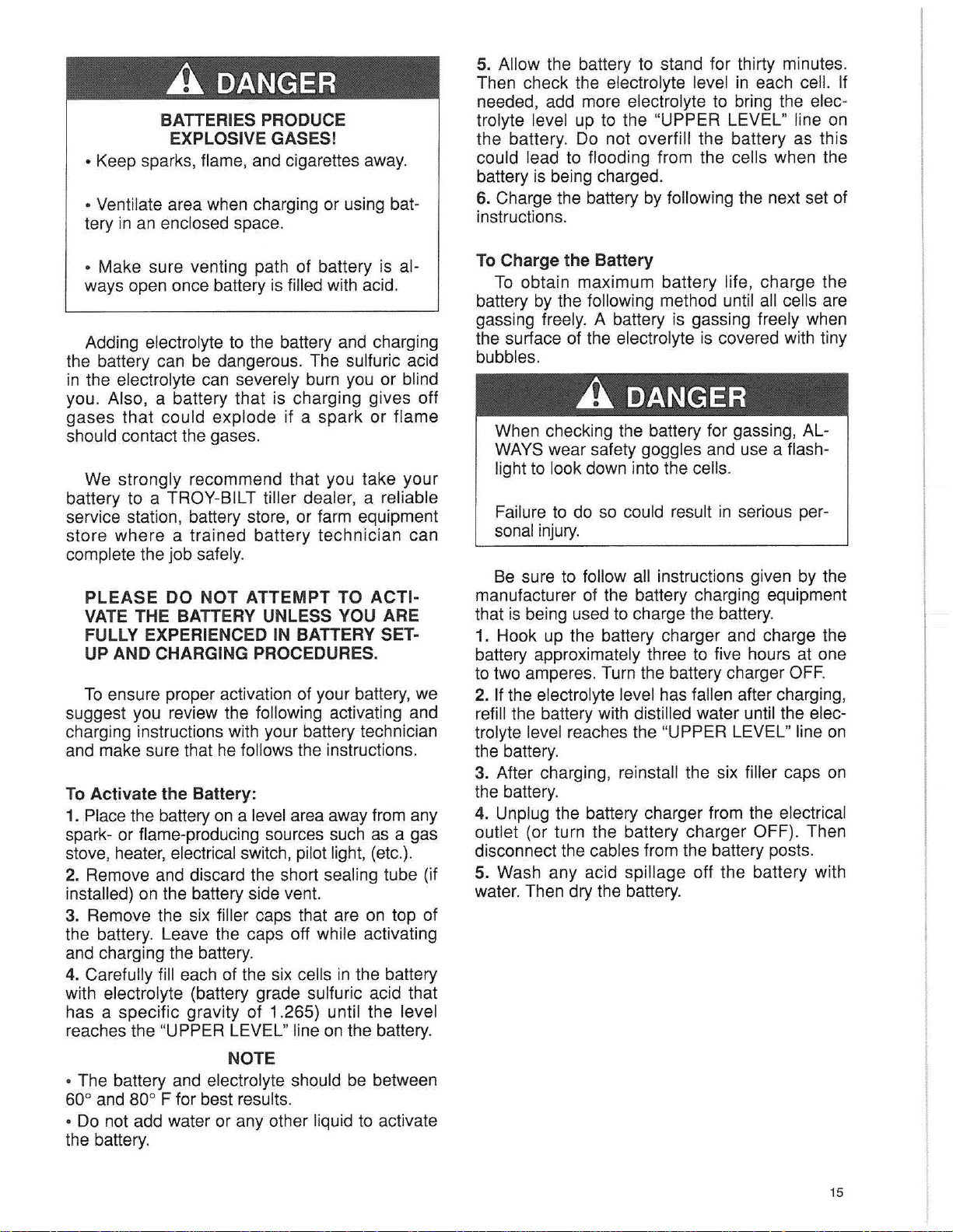
Compare the parts in your tiller's electric start
hardware package with the parts shown
2-22. The parts listed below are keyed to the
hardware items in the photo.
1. Battery (for shipping purposes, it is either se-
cured to the battery support bracket or
tective carton).
2. Vent tube.
3. Screws and nuts (used to attach battery ca-
bles to battery).
in Photo
in
a pro-
ECONO-HORSE'" or
STEP 10: BATTERY ACTIVATION
AND CHARGING
NOTE
Your battery was shipped to you
have battery electrolyte solution (battery grade
sulfuric acid) added to the battery.
have the battery fully charged before using it on
your tiller.
A
• Electrolyte is a sulfuric acid solution.
DANGER
DRY.
You
You must
then must
Photo 2-22: The Electric Start parts.
14
• Avoid spillage and contact with skin, eyes,
and clothing.
• To prevent accidents, wear protective clothing, rubber gloves, and shield eyes with
2
t
3
n
•
safety goggles when working near battery.
• Neutralize acid spills with baking soda and
water solution. Neutralize empty container
with baking soda and rinse with water.
ANTIDOTE: External contact: Flush with water.
s-
Eye
prompt medical attention.
ANTIDOTE : Internal: Drink large quantities of
wate r or milk . Follow with milk of magnesia,
beaten eggs, or vegetable oil. Call physician immediately.
Flush with water for 15 minutes and get
Page 17
A
BATTERIES PRODUCE
EXPLOSIVE
• Keep sparks, flame, and cigarettes away.
• Ventilate area when charging or using battery in an enclosed space.
DANGER
GAS
ES!
5. Allow the battery to stand for thirty minutes.
Then check the electrolyte level in each cell. If
needed, add more electrolyte to bring the electrolyte level up to the "UPPER LEVEL" line on
the battery. Do not overfill the battery as this
could lead to flooding from the cells when the
battery is being charged.
6. Charge the battery by following the next set of
instructions.
• Make sure venting path of battery is always open once battery is filled with acid.
Adding electrolyte to the battery and charging
the battery can be dangerous. The sulfuric acid
in the electrolyte can severely burn you or blind
you. Also, a battery that is charging gives off
gases that could explode if a spark or flame
should contact the gases.
We strongly recommend that you take your
battery to a TROY-BILT tiller dealer, a reliable
service station, battery store, or farm equipment
store where a trained battery technician can
complete the job safely.
PL
EASE
VATE THE BATTERY U
FULLY EXPERIENCED IN BATTERY SET-
AND
UP
To ensure proper activation of your battery, we
suggest you review the following activating and
charging instructions with your battery technician
and make sure that he follows the instructions.
Activate the Batte ry:
To
1. Placethe battery on a level area awayfrom any
spark- or flame-producing sources such as a gas
stove, heater,electricalswitch, pilotlight, (etc.).
DO N
CHARGING PROCEDURES.
OT
ATTEMPT
NLESS
TO
YOU ARE
ACTI-
2. Remove and discard the short sealing tube (if
installed) on the battery side vent.
3. Remove the six filler caps that are on top of
the battery. Leave the caps off while activating
and charging the battery.
4. Carefully fill each of the six cells in the battery
with electrolyte (battery grade sulfuric acid that
has a specific gravity of 1.265) until the level
reaches the "UPPER LEVEL" line on the battery.
To Charge the Battery
To obtain maximum battery life, charge the
battery by the following method until all cells are
gassing freely. A battery is gassing freely when
the surface of the electrolyte is covered with tiny
bubbles.
A
When checking the battery for gassing, ALWAYSwear safety goggles and use a flashlight to look down into the cells.
Failure to do so could result in serious personalinjury.
Be sure to follow all instructions given by the
manufacturer of the battery charging equipment
that is being used to charge the battery.
1. Hook up the battery charger and charge the
battery approximately three to five hours at one
to two amperes. Turn the battery charger
2. If the electrolyte level has fallen after charging,
refill the battery with distilled water until the electrolyte level reaches the "UPPER LEVEL" line on
the battery.
3. After charging, reinstall the six filler caps on
the battery.
4. Unplug the battery charger from the electrical
outlet (or turn the battery charger OFF). Then
disconnect the cables from the battery posts.
DANGER
OFF.
5. Wash any acid spillage off the battery with
water. Then dry the battery.
NOTE
• The battery and electrolyte should be between
0
and 800F for best results.
60
• Do not add water or any other liquid to activate
the battery.
15
Page 18

STEP11: INSTALLING THE
BATTERY ON THE TILLER
Photo 2-
1. Use both hands to carefully place the battery
on the battery mounting bracket. The battery
posts should face to the rear of the tiller. The
positive
of the tiller and the negative (-) post should be
on the right-hand side of the tiller.
23
: Installing the Battery.
(+) post should be on the left-hand side
3. Use the two 1/4" -20 x 1 1/4" carriage bolts,
1/4" lockwashers, and 1/4"-20 nuts to secure the
hold-down bracket to the b
bracket. Insert the bolts from beneath the battery
mounting bracket, up through the battery holddown bracket, and secure them with the lockwashers and nuts. Use a 7/16-inch wrench to
evenly tighten both nuts. Do not tighten the nuts
so that the tabs on the battery hold-down bracket
become bent.
attery
mo
unt
ing
STEP 12: INSTALLING
THE BATTERY CABLES
1. The Positive battery cable is already conleno
nected at one end to the so
mounted a few inches below the battery on a
post. You are to connect the loose end of the
positive cable to the positive
tery. Use a bolt and nut from the hardware bag.
Use a screwdriver and a
the bolt. See Photo 2-25.
(+) post on the bat-
3/8" wrench to tighten
id which is
A WARNING
• Be sure that the battery is positioned on
the tiller as explained in Step 1. Hooking the
battery cables to the wrong posts could re-
sult
in damage to the battery and other
electrical parts.
• Do not touch the positive (+) battery post
and any surrounding metal with tools, jewelry, or other metal objects. Doing so could
cause a short circuit that could result in
electrical burns or an explosion of battery
gases.
2. Place the battery hold-down bracket over the
battery. Center the bolt holes in the lower part of
the hold-down bracket with the bolt holes in the
battery mounting bracket. Make sure that the
Engine Ignition Switch is on the forward side of
the battery.
Photo 2-25: Attach Positive Cable to Battery.
2. Slide the black rubber boot up the positive
cable and slip it over the positive battery post.
3. The Negative cable is already connected at
one end to one of the mounting bolts securing
the solenoid to the post. This is the grounding
point for the negative
cable-connect
end of the negative (-) cable to
the negative battery
the last nut and
last bolt to securely attach the
negative battery
cable to the negative (-) battery
post.
the loose
pos
t. Use
Photo 2-24:Securing the Battery in Place.
16
Photo 2-26: Attach the Negative
Battery Cable to
the battery.
Page 19

4. Use a 3/8" wrench to check the tightness of
the upper mounting bolt on the starter solenoid.
This bolt
ground location. Scrape away any paint between
the cable and the bolt as this would prevent a
proper electrical ground.See Photo 2-27.
secures
the Negative Cable to its
-1
Photo
2-27
: The Negative Battery Cable must be se-
curely grounded to the Upper Mounting Bolt on the
Solenoid.
STEP 14: CONNECT WIRING HARNESS TO IGNITION KEYSWITCH
Slide the wiring harness connector over the
prongs on the back of the Ignition Keyswitch .
You
r keyswitch has either a 3-prong or 5-prong
design. See Sketch 2-29 or 2-29A.
•
STEP 13: INSTALLING THE
BATTERY VENT TUBE
1. Push the battery vent tube down into the vent
tube sheath. Attach the upper end of the vent
tube to the side vent on right side of battery.
A WARNING
Be sure that the vent tube does not become
kinked, folded, or pinchedwhen you install it.
Improper venting could cause the battery to
explode, resulting in personal injury or property damage.
Sketch
Ignition Keyswitch . The 5-prong design is shown.
Inset Sketch 2-29A
you may have instead 01the 5-prong type.
HORSE'" or PONY
begin to operate the tiller, please read the rest of
this Owner/Operator Manual so that you become
familiar with the location of, and the operation of,
the various tiller and engine controls.
the tiller controls so that you understand what
each one does. After you've done this, move the
tiller to a safe, level area to practice starting the
engine and maneuvering the tiller without actually tilling. Make sure that the depth regulator
lever is in the "travel" position (one of the higher
notches) while you're becoming fami liar with
your newtiller.
while you 're practicing in case you have any
questions about operating your tiller.
2-29:
Connect the Wiring Harness to the
-sh
ows the 3-prong type which
You
're now finished assembling your ECONO-
®Til
ler.
Before you add gasoline to the gas tank and
Without starting your tiller's engine, operate
Take this Manual along for ready reference
l!o...
Photo 2-28: Installing the Battery Vent Tube.
A WARNING
To avoid serious personal injury or damage
to equipment, do not attempt to operate the
tiller or its engine until after you've read and
understood all of the Safety, Controls, and
Operating Instructions in this Manual, in the
Engine Owner's Manual, and in other litera-
ture you may receive.
17
Page 20

Section
T
ill
er
And
3:
Eng
...
in
...e......C....o....
n....,t_r
...
o....,ls
......
_
Before attempting to operate
functionofall the operational c
and
Practice
of
the
using
controls
thesecontrols-with
and feel
conf
ident
you
r new tiller, become
ontr
ols.
the engine
with
each one of them.
shut
thoroug
off-until
hly
familiar with the location of
you
unders
tand the operation
TILLER CONTROLS
There are four tiller controls you will be using when you operate your tiller. These controls are: the
Wheel Gear Lever (ECONO-HORSE and PONY Models only). the Forward Clutch, the Maneuvering
Clutch, and Depth Regulator Lever. Referto Photos below for the location of these controls.
MANEUVERING WHEELGEAR
CLUTCH , /
.~
,!:
-
~
~~~
LE
VER
ECON O
-HOR
ENGINETHROn l E
LEVER
HANDLEBAR
HEIGHT
ADJU STMENT
/
SE and PON Y M
ODEL
COf'l
\lol
s
HANDLEBAR
HEIGHT
"D
i TMENT
DEPTH
REGULATOR
LEVER-
DEPTH
RE
GULATOR
LEVER
RECO IL
STARTER
Photo
3-t
: Location of controls on ECONO-HORSE
and PONYModels.
Wh
eel
Gear Lever
(Ec
ono-Horseand P
This lever is located on the left-hand side of
the handlebar control panel. It has two positions:
ENGAGE and DISENGAGE (FREE WHEEL).
The ENGAGE position allows power from the
engine to turn the wheels and tines whenever:
a. The Forward Clutch is engaged. OR
b. The Maneuvering Clutch is engaged in either
forward or reverse.
The DISENG AGE (FREE WHEEL) position
should only be used when the engine is not running. Use the DISENGAGE (FREE WHEEL) position ONLY when you are rolling the tiller to another location.
ony
Models only)
AIR ClEANER
Photo
Model tiller.
3-t
A: Location
.A
NEVER place the Wheel Gear Lever in DISENGAGE (FREE WHEEL) when the engine
is running.
Having the Wheel Gear Lever in DISEN-
GAGE (FREE WHEEL) and then engaging
the tines/wheels with either the Forward
Clutch or the Maneuvering Clutch could
allow the tines to propel the tiller rapidly forward or backward.
Failure to follow this instruction could result
in personal injury or property damage.
of
controls on the
DANGER
JUN
IOR
18
Page 21

To operate the Wheel Gear Lever:
1. Roll the tiller a few inches forward or back-
ward while you gently move the Wheel Gear
Lever ahead to ENGAGE. Don't force the lever
into ENGAGE (see Pg 43 for lever adjustment).
2. To place the Wheel Gear Lever in DISENGAGE (FREE WHEEL), simply move the lever
rearward. You don't have to move the tiller when
you move the Wheel Gear Lever into DISENGAGE (FREE WHEEL).
-\
\-.~
- . ,
+ ii .
--.:
,-
;,"=
I !
To Engage
A. Make certain the engine is stopped and the
spark plug wire is disconnected.
B. Raise one wheel off the ground and place a
sturdy block beneath the transmission.
C. Remove the hair pin cotter and pull the Wheel
Drive Pin out.
D. Slide the wheel outward on the shaft and re-
place the Wheel Drive Pin through the hole in
the wheel hub AND the hole in the wheel shaft.
Replace the hair pin cotter through the Wheel
Drive Pin, pushing the cotter pin in as far as it
will go. See Photo 3-2A.
E. Repeat these steps with the other wheel.
the
Wheels in WHEEL DRIVE:
A WARNING
Photo 3-2: The Wheel Gear Lever in "ENGAGE" po-
sition. Econo-Horse and Pony Models only.
Wheel
place by a Wheel Drive Pin (Photo 3-2A). The
pins are used to engage and disengage drive
power to the wheels. Before starting the engine,
the Wheel Pins must be in the WHEEL DRIVE
position. Do this by inserting the pins through the
holes in the wheel hubs AND the holes in the
wheel shaft. This "locks" the wheels to the wheel
shaft, so they will turn when either the Forward
Clutch or the Maneuvering Clutch is engaged.
ning, the
WHEEL". To permit this, insert the Wheel Drive
Pins through the wheel shaft holes only. When
this is done, the pins will keep the wheels on the
wheel shaft, but the wheels will be free to rotate
as they are no longer "locked" to the shaft.
DrivePins
Both wheels on the Junior tiller are held in
To move the tiller when the engine is not run-
wheelsmust
(Junior
Model
be able to "FREE
only)
A WARNING
NEVER
power if the wheels are in FREE WHEEL
position(Wheel Pins through wheel shaft
only). In FREE WHEEL, the wheels will not
hold the tiller back and the tines could propel the tiller rapidly, possibly causing loss of
control and serious injury or property dam-
age. Always engage the wheels in WHEEL
DRIVE position before starting the engine or
engaging
Clutch.
operate
the
Forward
thetiller
Clutch
under
or Maneuvering
engine
To avoid personal inju
on its side while adjusting the wheels. This
could cause gasoline to leak from the fuel
tank, resulting in an unsafe condition.
Photo 3-2A : Install Wheel Drive Pin through wheel
hub and shaft for WHEEL DRIVE position.
To Engage the Wheels in FREE WHEEL:
A. Repeat Steps A, B, and C of the previous
"Wheel Drive" engagement instructions.
B. Slide the wheel fully inward on the shaft.
C. Place Wheel Drive Pin through hole in wheel
shaft only, as shown in Photo 3-28.
D. Replace the hair pin cotter through the Wheel
Drive Pin. Push it in as far as possible.
E. Repeat Steps A through D with the other
wheel. Remove the support block.
Photo
shaft only for FREE WHEEL position.
3-2
8 : Install Wheel Drive Pin through wheel
ry,
do not lay the tiller
19
Page 22

Forward Clutch
This control is the two interconnected "paddies" that hang down beneath the control panel.
It is used to engage and disengage both the
wheels and the tines in forward motion.
To operate the Forward Clutch:
Before engaging the Forward Clutch, first
make sure that the Wheel Gear Lever (EconoHorse and Pony Models only) is in ENGAGE. On
the Junior Model, the Wheel Drive Pins must be
through the holes in the wheel hubs and the
wheel shaft. Then lift up on either or both of the
"paddles" and hold it (or them) against the underside of the handlebar grips. As long as you hold
the "paddles" in this position, both the wheels
and tines will turn.
Tostop forward motion of the tines and wheels
when you have the Forward Clutch engaged,
simply release the "paddles" and allow them to
drop downward. Both the wheels and tines will
stop rotating
-the
engine will continue to run.
Maneuvering Clutch
This control is located at the rear of the left-
hand side of the control panel. It is the rod hav-
ing a 90° bend and a black plastic grip.
The Maneuvering Clutch is used to precisely
maneuver the tiller in either a forward or backward direction. Pulling the Maneuvering Clutch
out (for REVERSE) or pushing the Maneuvering
Clutch in (for FORWARD) engages both the
wheels and tines.
If you want to precision till near an obstacle,
release the Forward Clutch "paddles" and push
in the Maneuver ing Clutch Lever. When you
want to stop tilling with the Maneuvering Clutch
-it
Lever, release it
NEUTRAL
If you want to move the tiller forward for a
short distance or in close quarters, release the
Forward Clutch paddles , lift up on the handlebars until the tines clear the ground. Then push
the Maneuvering Clutch in. To stop forward motion, release the Maneuvering Clutch Lever.
The only way you can make the tiller move in
reverse is by using the Maneuver ing Clutc h
Lever. Lift up on the handlebars until the tines
clear the ground and then pull the Maneuvering
Clutch Lever out. The tines and wheels will both
move in reverse direction for as long as you hold
the Maneuvering Clutch Lever in REVERSE. To
stop reverse motion of the tines and wheels, simply release the Maneuvering Clutch Lever.
will automatically return to
Photo 3-3: The Forward Clutch.
A WARNING
NEVER move the Maneuvering Clutch into
either FORWARD or REVERSE unless the
Wheel Gear Lever on Econo-Horse and
Pony Models is in ENGAGE. On
Models, the Wheel Drive Pins must be in
WHEEL DRIVE POSITION.
Placing the Maneuvering Clutch in either
FORWARD or REVERSE when the wheels
are not engaged could allow the tines to
rapidly propel the tiller forward or backward.
Failure to follow this warning could result in
personal injury or property damage.
20
Junior
A WARNING
• When moving the tiller in reverse, always
look behind you to check for, and avoid,
obstacles.
• Never attempt to till in reverse.
Failure to follow these instructions could result in personal injury.
Photo 3-4: The Maneuvering Clutch.
Page 23

Depth Regulator
The lever at the rear of the tine hood is the
Depth Regulator Lever. Pulling back on this lever
and moving it either up or down allows you to
control the depth of tine penetration in the soil.
When you move the Depth Regulator Lever all
the way down (engaging the highest notch on
the depth regulator), you put the tiller in the
"travel" pos ition . This position allows you to
move the tiller without damage to your lawn by
allowing the tines to clear the ground by approximately
the way up (engaging the lowest notch on the
depth regu
depth (approximately six to eight inches, depending on soil conditions).
lower Depth Regulator Lever settings and
gradually increase the tilling depth and not
attempt to t
1-1/2 inches.
When you move the Depth Regulator Lever all
lator
), you
You
should begin tilling at one of the shal-
ill
too deeply too soon.
get
the
deepest
tilling
A WARNING
Handlebar Height Adjustment
To adjust
the
handlebar height:
1. Loosen the handlebar height adjustment han-
dle until the keys on the bottom of the keyed
washer can clear the slots in the curved handlebar height adjustment bracket.
2. Move the handlebar up or down to the height
you desire. Align the hole in the handlebar crossbrace with one of the four slots in the curved
handlebar height adjustment bracket.
3. Align the keys on the bottom of the keyed
washer with the slot in the curved handlebar
height adjustment bracket. Screw the handlebar
height adjustment handle into the hole in the
handlebar crossbrace. Tighten it securely.
To avoid injury, always place the Depth
Regulator Lever in the TRAVEL position before starting the engine. This position prevents the tines from touch ing the ground
until you are ready to begin tilling.
Photo 3-6: Adjusting the Handlebar height.
A WARNING
• When you change the handlebar height,
you MUST readjust the Forward Clutch
mechanism.
• When ad
Clutch mechanism, shut engine off, disconnect spark plug wire and prevent it from
touching the spark plug.
Failure to do this could allow the Forward
Clutch mechan ism to operate improperly,
which could resu lt in personal i
property damage.
justing
or
checking
Forward
njur
y or
Photo 3-5: The Depth Regulator Lever.
4. Readjust the Forward Clutch mechanism by
performing the following steps:
a. Remove the inner hairpin cotter from the
lower end of the Forward Clutch Rod.
21
Page 24

b. Use Photo 3-7 to determine which hole in
the swivel plate you should insert the lower
end of the Forward Clutch Rod into. For example, if you have the handlebar height setting at
position number 1 (on the curved handlebar
height adjustment bracket) insert the lower
end of the Forward Clutch rod into hole number 1 on the swivel plate.
Photo 3-7: Handlebar Height setting
Clutch positioning.
C. Insert the lower end of the Forward Clutch
and
Forward
Rod into the proper hole in the swivel plate.
Secure it in place by reinstalling the hairpin
cotter in the inner hole in the Forward Clutch
Rod.
d. To make sure that you have selected the
correct hole in the swivel plate:
(1). Stand on the right-hand side of the tiller.
Pull the Forward Clutch Lever up and hold it
in place.
(2). Check the gap between the E-Ring and
the lower end of the bracket on the Forward
Clutch Lever. The gap should be 3/16" to
5/16". If you do not have a ruler handy, five
pennies
are
approximately
5/16"
Refer to Photo 3-8.
e. If you are unable to get the 3/16" to 5/16"
gap, you'll have to readjust the Forward Clutch
Rod as follows:
(1). Refer to Photo 3-7 and make sure that
you have the Forward Clutch Rod in the
correct hole in the swivel plate.
thick.
3/16 "-10-5 /16"
REQUIRED GAP
Photo 3-8: Measuring the gap between the Forward
Clutch Bracket and the E-Ring.
(2). Insert the lower end of the Forward
Clutch Rod into this hole.
(3). Pull the Forward Clutch Lever up and
hold it in place.
(4). Check the gap between the E-Ring and
the
lower
end
of
the
Forward
Clutch
bracket.
If the gap is greater than 5/16", you'll have
to release the Forward Clutch Lever, re-
move the hairpin cotter from the inner hole
in the lower end of the Forward Clutch Rod,
move the Forward Clutch Rod away from
the swivel plate, and turn the rod counterclockwise (as viewed from the front of the
tiller) to decrease the gap.
If the gap is less than 3/16", you'll have to
release the Forward Clutch Lever, remove
the hairpin cotter from the inner hole in the
lower end of the Forward Clutch Rod, move
the Forward Clutch Rod away from the
swivel plate, and turn the rod clockwise (as
viewed from the front of the tiller) to increase the gap.
f. After getting the correct gap, make sure that
you reinstall the hairpin cotter in the inner hole
in the lower end of the Forward Clutch Rod.
ENGINE CONTROLS
Please read the following information about engine controls and operation.
Engine Owner's Manual that you received in your literature package.
Start
Electric Start Models
1. Check to make sure that the spark plug wire is
securely attached to the spark plug.
2. Make sure that the Wheel Gear Lever is in
"ENGAGE" on Econo-Horse and Pony Models.
22
ing
YourEng
ine-Recoi
l
Startand
On Junior Models, there is no Wheel Gear Lever,
but the Wheel Drive Pins should be through the
wheel hubs and wheel shaft holes in "ENGAGE."
3. Move the Depth Regulator Lever all the way
DOWN so the tines are in the "travel" position
(they should clear the ground by about
You
should also read the
1'
12")
.
Page 25

4. Move the Carburetor Choke Lever to "FULL
CHOKE" position (in the direction of the arrow on
Tecumseh engines; toward "Choke" on Briggs
Stratton engines). See Photo 3-9 for the EconoHorse's Tecumseh engine choke control; Photo
3-10 for the Pony's Briggs
& Stratton engine
choke control; and Photo 3-11for the Junior's
Tecumseh engine choke control.
Photo 3-9:
Econo-Horse
Model-ehoke
lever on the 6
Horsepower
Tecumseh
gine.
Photo 3-10:
Pony Modelchoke lever on
the 5HP Briggs
engine.
en-
pull the rope outward, be sure that nothing is
hind you.
&
Photo.3-13: Use
starter rope to start
engine.
7. For Electric Start models, turn the Engine
Ignition Switch to "START."Don't keep the switch
in START for longer than ten seconds. You may
have to try this several times before the engine
starts - allow the engine to come to a complete
stop before you turn the switch to START again.
When the engine starts, release the key; it will
automatically return to "RUN."
8. After the engine is running, gradually move
the Carburetor Choke Lever to NO CHOKE (in
the opposite direction of Choke).
be-
3-11: the
Photo
Junior Mode
choke lever on
the 4HP
Tecumseh
gi
ne.
l-
en-
5. Move the Engine Throttle Lever (on the righthand side of the control panel) to "START."
Photo 3-12: Engine Throttle Lever.
6. For Standard Start models, grasp the starter
rope handle with one hand. Brace the tiller by
placing your free hand on the gas tank. Pull the
starter rope slowly until you feel resistance. Then
pull the starter rope out rapidly...but let it rewind
slowly. You may have to repeat this procedure
several times until the engine starts. When you
Start
ing
theElectric
Start
Engine
with
the
Recoil Starter Rope
If necessary, the electric start engine can be
started with the recoil starter rope. Before doing
so, be sure to follow the procedure below.
1. If the battery is in good condition (not "dead"
or damaged), keep it on the tiller. This lets it
recharge during engine operation. However,
be-
fore starting the engine with the recoil starter
rope, make sure the
UPPER LEVEL line with electrol
batte
ry is filled to the
y1
e.
2. If the battery is "dead" or damaged, remove it
from the tiller and have it tested by a qualified
technician. Before using the starter rope to start
the engine, disconnect the positive battery cable
from the starter solenoid. Reinstall it after replac-
ing the battery.
IMPORTANT-When starting the engine with the
starter rope, turn the Ignition Key Switch to RUN.
Also move the Engine Throttle Lever to
START.
Stopping the Engine
To stop the wheels/tines at any time, simply
release the Forwa rd Clutch "paddles" or the
Maneuvering Clutch Lever (whichever one you
have engaged).
1. Tostop the engine on a Standard Start model,
move the EngineThrottle Lever to STOP.
2. To stop the engine on an Electric Start model,
you can either move the Ignition Key Switch to
OFF or you can move the Engine Throttle Lever
to STOP.
23
Page 26

Section
4:
.Q.p
(Section 1 ) and the Tiller and Engine operating in
tempttooperate your tille r.
use it in
ning the tiller
sit
yo
er
at
ion
Please be sure
Take a few mi
the
ion (Depth Regulator Lever p
Only after
ur
garden.
MANEUVERING WHEEL GEAR
CLUTCH
that
nutes
garden. Locate a clear, level area and practice engaging the
back
and forth. When you do this, make sure that the tines are in the
you
've
Of
you've
to familiarize yourselfwith the basic operationofyour
become
./
T
read, fu
ushe
comp
LEVER
ill
er
lly
understand, and a
d all the way down).
letely fa
mil
iar
struct
wit
ECONO-
ions (Sect
h your tille r
lways
HORSE
follow the Safety In
ions
3 and 4) before you at-
tiller
till
er controls and run-
shou
ld you begin
and PONYMODEL controls
stru
cti
before you
"tr
avel" po-
using
ons
it in
FORWARD
CLUTCH
LEVERS
,/
ool
~~
=:
I
.., LEVER
DEPTH
REGULATOR
LEVER
~~------
-
ENGINE THROTTLE
HANDLEBAR
HEIGHT
ADJUSTMENT
CHOKE
VER
LE
Photo 4-1: Operating
24
I
your
TROY-BILT Rototiller is easy
and
so rewarding .
Page 27

BEFORE STARTING, ALWAYS:
1. Check the engine oil level; add oil as necessary to bring the level up to the FULL mark on
the dipstick or to the point of overflowing if your
engine has an oil fill tube.
2. Make sure the engine air cleaner element is
clean and the air cleaner assembly is tight.
3. Be sure the gas tank has clean, fresh gasoline.
The gas tank cap must be screwed on tightly.
4. Check the spark plug wire; make sure that it is
securely attached to the spark plug.
5. Put the Wheel Gear Lever (on Econo-Horse
and Pony Models) in ENGAGE. On Junior tillers,
the
Wheel
Dri ve
Pins
must be ENG
AGED
through the wheel hubs and the wheel shaft.
TO BEGIN TILLING:
1. Make sure that the Wheel Gear Lever is in
ENGAGE on Econo-Horse and Pony Models. On
the Junior Model, the Wheel Drive Pins have to
be engaged.
2. Move the Depth Regulator Lever to the de-
sired position.
When practicing with your tiller or when moving the tiller to or from the garden, keep the tines
in the "travel" position.
When till ing, you
must
move
the
Depth
Regulator Lever to the desired setting, increase
the engine speed, and then begin tilling.
3. Start the engine and allow it to warm up before increasing the engine speed.
4. For forward motion of the wheels/tines, pull
the Forward Clutch "paddles" up and hold them
up against the handlebars.
If you want to go forward in close quarters,
push the Mane uvering C
ch Le
ver
in. The
lut
tines/wheels rotate while you hold the lever in.
5. For REVERSE motion of the wheels/tines, lift
the rear of the tiller up until its tines clear the
ground and then pull the Maneuvering Clutch
Lever out. Hold the Maneuvering Clutch Lever
out for as long as you need to move in reverse.
To stop
reverse
moti on, let go of
the
Maneuvering Clutch Lever. It will automatically
return to NEUTRAL.
TURNING AROUND
Turning your tiller around is f
should practice this maneuver before you take
your tiller into the garden for the first time. See
Photos 4-2 and 4-3.
The key to turning around is remembering that
the balance point of your tiller is the wheels.
When ready to turn around, lift up on the handlebars to find where the engine and tines are balanced. Then push sideways on the handlebar to
move the tiller in the direction of the turn.
air
ly easy. You
Photo 4-2: When you reach the end of a row, slow
the engine down and lift up
raise the tines Irom the soil. The Econo-Horse Model
is shown.
Photo
4-3: Use the wheels as a pivot point to balance
the engine and tines. Push the handlebars sideways
to move the tiller in the direction of the turn, and continue up the n
Model tiller.
ext
row. Shown is the Econo-Horse
on the handle bars to
STOPPING THE TILLER AND ENGINE
1. To s
orward
F
Maneuvering Clutch Lever (whiche ver control
you have engaged).
2. If
Engine Throttle Lever to STOP. If you have an
electric start model, you could also turn the
Engine Ignition Switch to OFF.
cedures stops the engine, move the choke lever
to FULL CHOKE. Do not use this practice except
in an emergency as it could lead to engine damage. Check the throttle cable adjustment and
readjust it or replace the cable if necessary.
top
the
wh
eel s/
tin
es , release the
Clut
you
ch "paddles" or re
want
to
stop
the e
ngi
lea
se the
ne, move the
In an emergency, if neither of the above pro-
25
Page 28

CHANGING SPEEDS(Econo-Horse
Model tiller only)
The ECONO-HORSE'" tiller has dual speeds
for the wheels and tines. Changing the speed
range is just a matter of moving the forward drive
belt from one set of grooves in the engine-driven
pulley and the transmission pulley to the other
set of pulley grooves.
Use the LOW speed belt range for jobs which
need more power such as tilling sod and unworked soil; or for tilling under cover crops or ex-
tremely heavy weeds. Your ECONO-HORSE
tiller is shipped to you with the belt in the LOW
range. Keep the belt in this range while you are
familiarizing yourself with the operation of the
tiller. After you've gained experience with the
tiller, then you can experiment with the HIGH
speed belt range.
Use the HIGH speed belt range for situations
like shallow cultivation, final seedbed preparation , or for power composting heavy leaves,
straw,
However, if the soil you are tilling this material
into is very hard, you may have to return to the
LOW speed belt range for better results.
There is a decal on the top of the belt cover that
shows the belt positions for the two speeds.
hay,mulch
WIR
, or
composted
BE~
mater
ial.
To change from LOW SpeedtoHIGH Speed:
1. Place the Wheel Gear Lever in DISENGAGE
(FREE WHEEL).
2. Use a
secure the belt cover to the tiller.
3. From underneath the tiller, work the forward
drive belt into the center groove in the transmission pulley.
4. Push up on the forward drive belt to get slack
where the belt goes around the engine-driven
pulley.
5. Work the belt into the forward groove on the
engine-driven pulley.
Photo 4-5: Removing Belt Cover.
1/2" wrench to remove the two nuts that
,
,
I
A WARNING
Before changing belt speeds, stop the en-
gine, allow the engine to cool, disconnect
the spark plug wire and prevent it from
touching the spark plug, and remove the
Ignition Switch key.
Failure to follow these instructions could result in personal injury or property damage.
4
-6:
Photo
Speed Groove of TransmissionPulley.
Photo
Speed Position on Engine-Driven Pulley.
Moving
4-7
: Moving Forward Drive Belt into High
Forward
Drive Belt into High
26
Page 29

NOTE
If the belt only goes part-way into the forward groove of the engine-driven pulley, pull
on the start rope to turn the engine-driven
pulley to force the belt into the groove.
6. Reinstall the belt cover. Use the 1/2" wrench
to securely tighten the nuts.
To change from HIGH speed to LOW speed:
A WARNING
Before changing belt speeds, stop the en-
gine, allow the engine to cool, disconnect
the spark plug wire and prevent it from
touching the spark plug, and remove the
Ignition Switch key.
Failure to follow these instructions could re-
sult in personal injury or property damage.
1. Move the Wheel Gear Lever to DISENGAGE
(FREE WHEEL) .
2. Remove the belt cover by removing the nuts
on the back of the cover with a 1/2" wrench. See
Photo 4-5.
3. Move the forward drive belt into the rear
groove on the engine-driven pulley.
5. Reinstall the belt cover. Use the 1/2" wrench
to securely tighten the nuts.
Phot
o 4
-8:
Moving
Speed Position on Engine-Driven Pulley.
Forwa rd Drive Belt
int
o Low
NOTE
If the forward drive belt will not slip all the
t~
e
way into
rear groove on the enginedriven pulley, pull the recoil starter rope
while forcing the belt to the rear.
4. From underneath the tiller, work the forward
drive belt from the center groove on the transmission pulley to the rear groove.
TILLING IN THE GARDE N
Guiding Your Tiller
While tilling, relax and let the wheels pull the
tiller along while the tines do the digging. Walk
alongside the tiller on the side that is not yet finished (to avoid making footprints in the just-tilled
soil) and lightly, but securely grip the handlebar
with one hand.
Please do not push down on the handlebars in
an attempt to force the tiller to dig deeper. Doing so takes the weight off the wheels, reduces
traction, and causes the tines to attempt to propel the tiller instead of just digging. This can
cause the tiller to skip rapidly across the garden.
Sometimes slight downward pressure on the
handlebars will help get through a particularly
tough section of sad or unbroken ground, but in
most cases this won't be necessary at all.
4-9
Photo
Speed Position on the Transmission Pulley.
Tilling Depths
: Moving
For
ward
Drive Belt into Low
When you start to till in the garden, remember
to take it easy. Don't try to take too deep a cut in
the first pass through sad or hard ground that
has not been tilled for years.
It's almost impossible to get down four or five
inches on the first pass through untilled soil. In
very hard, dry soil, you should start tilling at a
very shallow depth regulator setting, only an inch
or two deep for the first time. In each succeeding
pass, you can go down a few more inches, gradually working down to the depth you want (watering your garden a few days prior to tilling will
make the going much easier). At any time, if you
have difficulty getting down really deep, let the
newly worked soil set for a day or two. When you
return to it, the tilling will be easier.
27
Page 30

It is best not to work the soil when it is too
soggy or wet. Doing so will make too many
clumps that won't break up very easily. If time
will permit, always wait a day or so after heavy
rains for the ground to dry.
In most soils, it's best to start out at the third
or fourth notch of the depth regulator to break
through the upper inch or two of soil. The fastest
method is to till as deep as you can without making the tiller jump when it hits rocks, etc., but you
should wait until you are very familiar with the
tiller's operation before you use that procedure.
When you are cultivating your garden, the
tines should be adjusted to till to a depth of just
-1
/2" to 2" so they won't injure your plants'
1
roots, which grow close to the surface. If you no-
tice the tines are digging too deeply (even when
in the highest notch), then you may have to lift
up on the handlebars slightly. Also use the high
belt range when cultivating as the faster wheel
and tine speeds will help prevent the tiller from
digging too deeply.
Sketch 4-12. Again, overlap each pass to really
pulverize the entire garden area. (In very hard
ground. it might take three or four passes before
you make much headway.)
Sketch 4-12. Tilling pattern for unbroken ground.
If your garden is not wide enough to till length-
wise and then crosswise , then you should first
overlap by one-half a tiller width, followed by
successive passes at one-quarter tiller width.
This overlapping method will assure you of thor-
oughly breaking up the ground
-See
Sketch 4-13.
~('
''
,,
,.",...
Photo 4-10: Cultivating.
Tilling Patterns
''k~~
_. 1f..,"'--1
'\-
~"
..
",,""
When preparing a seedbed, go over the same
path twice in the first row, then overlap one-half a
tiller width on the s
ucceeding
passe
s-see
Sketch 4-11. After going up and down the rows
in one direction, make a second pass at a right
angle
Sketch 4-11: This is the tilling pattern recommended
for previously worked soil. Overlap each row one-half
across
your ea
rlierpasses
- re
fer
to
a tiller width.
Sketch 4-13: Tilling pattern for narrow strips.
If you plan your garden carefully, you can
allow enough room between rows to cultivate, as
shown in Sketch 4-14. The Econo-Horse has a
tilling width of 18" (the Pony 16", and the Junior
14"), so leave that much distance between the
rows, plus enough extra plant growi ng room
above ground. Remember some crops take lots
om-
of ro
Sketch
wanted weeds.
like beans, tomatoes, and peas.
4-14: Cultivate between
pl
ants to uproot un-
28
Page 31

Choosing Wheel and Tine Speeds
With a little experimenting, you can soon find
the proper tilling depth, engine throttle setting ,
and wheel and tine speeds that are just right for
the piece of soil on which you are working. What
this means is:
1. You advance the throttle lever on the handle-
bars to keep the engine running at a sufficient
power level to do the job. Don't run your engine
at full throttle all of the time. Instead, try to judge
when the engine is providing the proper amount
ower
of p
Matching engine power to the work is easier on
the engine and on the tiller. The sound of your
engine operating will be your best guide.
- not too
iittle
, but not to o much.
2. You have the depth regulator set in a notch
which is not so deep that it causes the engine to
labor or the tiller to jump.
3. You have the tines turning over fast enough to
really break up the soil with a minimum number
of passes. Faster engine and wheel speeds may
be desirable to break up the last bits of soil or
vegetation when you are making final passes, or
when you are cultivating.
By the way, try to give your engine a "rest" period during tiiling operations by every so often letting it run at low idle for a minute or
any ioad on it. This practice of giving your engine
a break while you pick up rocks, prepare to start a
new row, or when just pausing for a moment will
improve fuel economy and add years to the life of
your engine.
When your tiller is working properly, you can
hear that the engine is not laboring very hard
and see that the tines are breaking up the soil
into small, thoroughly tilled bits.
Remember that the wheels have two functions. First they power the tiller in forward or in
reverse. Also, they turn much slower than the
tines, thus holding the tiller back while the tines
dig. Because the separately geared tines revolve
much faster than the wheels, they can easily
chop up, shred and bury organic material. The
tine hood aids in this process as sod, soil and
vegetation are thrown up against it by the revolving tines, where it is trapped momentarily before
being further broken up and put back in the gar-
den.
two-
without
Avoid
always try to walk alongside the tiller on the side
that is not yet finished.
well prepared, you can easily walk alongs ide
while guiding your tiller with one hand.
than just good appearance to your garden.
aids in preventing soil erosion and avoids "planting" unwanted weed seeds right back in your
newly tilled ground. It also leaves your soil nice
and loose, so that vegetable roots can penetrate
it easily.
Making Fo
When making final tilling or
Eliminating footprints contributes much more
otprin
ts
CU
ltivating passes,
If the ground has been
Clearing Debris from the Tine Area
Your Bolo Tines have a self-cleaning action
which just about eliminates most tangling in the
tines. But occasionally, dried out grass, stringy
stalks, or tough vines may become tangled. If
this happens, lift the tines out of the soil and run
your tiller in reverse for a few feet. This reverses
the direction of the tines and should unwind a
It
good deal of debris.
It isn't necessary to remove all the residue, but
don't let it build up to a point where it chokes off
the action of the tines. If reversing the tiller
doesn't work, then STOP the machine and engine and remove the tangled material by hand. A
small pocket knife or linoleum knife will help you
cut away the material.
A WARNING
Before unclogging the tines, stop the en-
gine, disconnect the spark plug wire and
keep it from touching the spark plug, re-
move the Engine Ignition key and allow the
engine and muffler to cool.
Failure to follow these instructions could re-
sult in personal injury or property damage.
29
Page 32

Normally, you can avoid most tangling problems by setting the depth regulator deep enough
to get maximum "chopping" action as the tines
chop the material against the ground, and by till-
ing under crop residues or cover crops while
they are still green, moist and tender.
Also, you might try swaying the handlebars
from side to side (about 6" to 12") while continuing to power compost. This "fishtailing" action
often clears the debris out of the tines.
Power Composting
It is essential that a garden be fed something
if it is to be bountiful year after year in the same
location. You must replenish the plant nut
prim arily nitrogen,
sium-
that you took away from the soil in the
phospho
rous and potas -
rients-
form of harvested vegetables and fruits. The first
place to begin is with crop residues, which include leftover leaves, vines, stems and roots.
Power compost these crop residues directly
into your garden soil as soon as they finish bearing. The sooner this is done, the better. Tender
green matter not only tills in easier, but provides
that much more good food for the earthworms
and other beneficial forms of soil life.
Standing cornstalks of reasonable height can
be power composted. Pushing over (but not uprooting) tall cornstalks will often make it easier
for your tiller to chop up the stalks. Keep the
tines clear of excessive tangling by "fishtailing" or
frequently using Reverse. Make several passes,
then return a few days later to finish off any remaining stubble.
After all the powercomposting has been done,
you should plant a "green manure" cover crop to
protect your soil during the off-season. Green
manures are also called "cover crops" or "catch
You
crops".
simply grow a crop of clover, alfalfa,
buckwheat, peas, beans, rye grass, grain, or
kale and then later till it into the soil, thus adding
far more nutrients than you have taken out.
Using Reverse To Help Turn
Around in Tight Areas
Using your tiller near obstacles like fences,
stone walls, sheds or trees needn't be a problem
if you use Reverse to help you maneuver the
tiller around and away from the obstacles. For
example, turning around at the end of a row in
the garden that's very near a fence is easy.
When at the end of a row, you can go right up
near the
obstac
le, then engage the t
iller
in
Reverse while holding the handlebars up and
turning the tiller at the same time. Alternating
brief ly be
tweengoing
Forward and then in
Reverse will let you complete your turn in a very
small area.
'1
Photo 4-16: Tilling under cornstalks.
After all the crop residues have been tilled
under, add more organic matter such as leaves,
grass clippings and even kitchen scraps. This organic matter will decompose and add even more
important nutrients to the soil to help plants
thrive next Spring.
30
Photo 4-17: Toturn around in cramped quarters, move
close to obstacle, then put the tiller in Reverse while
lifting up on the handlebars (to raise the tines out
the soil) and turning the tiller.
Tilling Near Obstacles Requires Caution
of
Always be sure to avoid coming too close to
any obstacles (fences, rock walls, posts, buildings, etc.) that could be damaged by your tiller,
or th at
could
causedamage
to your t
iller.
Whenever possible, stay away from objects such
as this. Tilling another few inches closer to an
obstacle just isn't worth the property damage
that could occur unexpected
AVOID
GROUND CABLES, WIRES OR GAS LINES!
AREAS
THA
ly.
T MAY HAVE
UNDER
·
Page 33

Before you do any tilling with your tiller,please
find out if there are any cables, electric lines or
gas lines that might have been installed underground by a local utility company or by a previous owner of your property. Ifthere are any lines,
avoid tilling near them. This is an IMPORTANT
SAFETY PRECAUTION that should be investigated fully until you know that you're tilling in a
safe area.
A WARNING
BEFORE
TELEPHONE OR UTILITY COMPANY IF
UNDERGROUND EQUIPMENT OR LINES
ARE USED IN YOUR AREA. Their representative will be glad to answer your questions and tell you if any of their equipment
or lines are buried underground on your
property.
Tilli ng Up and Down Slopes
If you must garden on a moderate slope, then
the best way to do so is by planting rows up and
down the slope. Tilling vertically in this manner
perm its you to use the entire area
seedbed as well as to provide enough room between rows so that you can cultivate between
them during the growing season (you lose these
valuable benefits when you terrace garden,
which is discussed next).
TILLING,
CONTACT
YOUR
foryour
Whenever you are tilling verticaliy on the
slightest slope, try to make your first pass uphill.
Your tiller digs in much more deeply going uphill
than it does downhill. The powered wheels of
your tiller pull the machine up the hill to do your
digging and also hold the tiller back while you go
downhill to prevent the tiller from going too fast.
In soft soil or weeds, you may have to lift the
handlebars up slightly as you go uphill. When
going back down the slope, overlap your first
pass by about half the width of the tiller.
Tilling Across Slopes with Terraces
Whenever a slope is too steep or too short for
vertical tilling, it may be necessary to till across
the slope laterally. The best way to achieve good
results tilling across the slope is to create ter-
races for your garden.
Terraces should be about two to three feet
wide. This means you'll be able to plant one or
two rows of plants and till under crop residues
and cover crops, but there may not be enough
room for cultivating with your tiller.
terraces too wide, you would be digging as much
as a foot into the uphill side of the terrace and
you would end up trying to grow vegetables in
the poor subsoilthere.)
First, make sure that the slope is not too steep
to till safely. Then start to terrace on the top of
the slope and
passes, your tiller can carve out a flat and wide
enough terrace for planting, as shown in Sketch
4-19. Each succeeding lower terrace is started
by walking belowthe terrace you're preparing.
work
down
. In
(If you make
three
or four
Photo 4-18: Tilling up a slope.
Gardening vertically does not involve much of
a soil erosion problem, as long as you put in
enough o
moisture-holding ability of your soil, and if you
avoid leaving footprints and wheel marks. Soil in
this condition is loose enough to prevent packing, and is held together well enough by those
organic materials so that it readily absorbs water.
rga
nic
mater
ial to improve
the
~
O
~.
e
~.
12" UNTILLED
O
~.
Sketch 4-19: Creating a terrace in
passes.
Make sure that you don't till the last 12" or
more of the downhill outside edge of each terrace-See
ken beneath the outside edge will help to pre-
vent terraces from breaking apart and washing
downhill. It also gives you a walking path between the terraces.
R E P EAT
just
three tilling
Photo 4-20. Keeping the soil unbro-
31
Page 34

Photo 4-20: Leave the outside edge (12"or more) unbroken to prevent erosion.
Tilling Across Slopes Without Terraces
If terracing isn't practical for you, then you can
till laterally across a slope, although we don't really recommend it. For best results, we urge you
to till vertically up and down a slope, or create
terraces.
First, make sure that the slope is not too steep
to till safely. Then, begin at the top of the slope
and overlap half of each tilled path, always keeping the uphill wheel in the soft, newly tilled soil.
Doing so will help keep the tiller more stable
across a relatively steep slope.
UPHILL TILLING NOTE
When tilling on slopes, be extra careful to see
that your engine crankcase is kept filled to either
FULL mark on the dipstick (6HP Tecumseh
the
engines)or to the top of the engine oil fill tube
(5HP Briggs and 4HP Tecumseh engines).
When tilling at the deepest settings and going
up a steep hill, the oil slants away from its normal level and can starve the engine of lubrication
as the engine's oil dipper may not be able to
reach the oil due to its slanted level. Keeping the
oil level at the
the protection of your engine.
To prevent engine damage from oil starvation,
check engine oil level at least every half-hour
during uphill tilling operations.
FULL mark is very important for
LOADIN G AND UNLOADING TILLER
A
Loading and unloading your tiller into a vehicle is potentially hazardous and we don't
recommend that you do so unless absolutely necessary, as this could result in personal injury or property damage.
However, if you must load or unload the
tiller,follow the guidelines given next.
• Shut the tiller engine off before loading or unloading. Allow the tiller engine to cool, disconnect the spark plug wire and prevent it from
touching the spark plug. (Remove the Ignition
Switch key on electric start models.)
·The tiller is too heavy (well over 200 pounds)
and bulky to lift safely by one person.
tiller, two or more people should share the load.
• We recommend that you use sturdy ramps and
that you manually (engine shut off) roll the tiller
into and out of the vehicle. This will require assistance from another person.
• Ramps should be strong enough to support the
tiller and the handlers. The ramps should provide
good traction to prevent slipping; they should
have side rails to guide the tiller up and down the
ramps; and they should have a locking device to
secure them to the vehicle bed.
32
WARNING
To
lift the
• The operator and handlers should wear sturdy
footwear that will help to prevent slips.
• Position the vehicle so the ramp angle is as flat
as possible (the less the incline of the ramp, the
better). Turn the vehicle's engine off and apply
the vehicle's parking brake.
• When going up ramps, stand in the normal operating position and push the tiller ahead of you.
Have a person at each wheel to turn the wheels.
• When going down ramps, walk backward down
the ramp with the tiller following you. Keep alert
for, and avoid any obstacles that could cause
you to fall. Position a person at each wheel to
control the speed of the tiller. Never go down
ramps tiller-first, as the tiller could tip forward.
• Have wooden blocks handy to place on the
downhill side of the wheels if you need to stop
the tiller from rolling down the ramp when un-
loading or loading. Use the blocks to temporarily
keep the tiller in place on the ramps while you
get a firmer grip on the handlebars, reposition
the tiller, etc. Also use the blocks to chock the
wheels in place after you've tied the tiller down.
• Once the tiller is in the vehicle, move the
Wheel Gear Lever to "ENGAGE" (on EconoHorse and Pony Models) or be sure the Wheel
Drive Pins are Engaged (Junior Model). This
locks the wheels in position and helps prevent
the tiller from moving. Then securely tie the tiller
down.
Page 35

Section
5:
Tiller
There are a few very important steps that you can perform in order to get the best performance and longest life from your tiller. These steps are: frequent engine oil changing, frequent
air cleaner element cleaning and replacing, keeping the engine cooling fins clean, lubricating
the tiller regularly, and keeping the belts adjusted properly.
You will be operating your tiller in a very dusty environment, often for extended time periods
at high temperatures. Proper maintenance is therefore very important.
And
Engine
Maintenance
A WARNING
Before performing any maintenance on your tiller, stop the engine,
allow it to cool, disconnect the spark plug wire and prevent it from
touching the spark plug, then remove the Engine Ignition key.
Failure to follow this instruction could result in personal injury or
property damage.
LUBRICATION
Proper lubrication is an essential part of your maintenance program. By oiling or greasing the lubrication points shown in Photos 5-1 and 5-2 at regular intervals,you will be sure of the best performance
from your tiller. Use ordinary clean engine motor oil (30 weight) where oil is called for. Use a good quality grease that has a metal lubricant added when possible; however, regular grease is acceptable.
•
Photo 5-1: Lubrication points common to the Econo-Horse, Pony,
and
JuniorModel tillers.
33
Page 36

1. Remove one wheel , clean the wheel shaft,
and apply a thin coat of grease. Repeat at the
other end of the.wheel shaft.
2. Grease the back, front, and sides of the Depth
Regulator Lever.
3. Oil the entire length of the Engine Throttle
cable (all models) and the Wheel Gear cable (except Junior ModeL) Just apply oil to the outside
of the cables, allow it to work its way inside, and
wipe off the excess oil.
4. Oil the threads on the
Adjustment Handle.
5. Oil the pivot points on the shifting mechanism.
6. Oil the handlebar pivot points.
7. Clean and grease the tine shaft on both sides
of the tiller. Inspect the tine shaft for rust, rough
spots, or burrs; especially near the holes. File or
sand any rust, rough spots, or burrs smooth and
then coat the tine shaft ends with grease to
make future removal easier.
Car
8.
careful not to spill any oil on the belts or pulleys.
efully oil the idler arm pivot points. Be
Handlebar
Height
TIGHTENING NUTS AND BOLTS
A WARNING
Before inspecting or servicing the tiller, stop
the engine, disconnect the spark plug wire
and keep it from touching the spark plug,
remove the Engine Ignition key and allow
the engine and muffler to cool.
Failure to follow these instructions could result in personal injury or property damage.
It's a very good idea to periodically check all
nuts, bolts, and screws on your tiller for tightness. Loose nuts, bolts, or screws can lead to
equipment failure, poor performance, or oil leaks.
Most nuts, bolts, and screws on your tiller are
easily visible.
There are also three end cap screws on the
rear end of your tiller's transmission that should
be inspected for tightness. Gently tilt the tiller forward on its engine and support it in this position.
Lift the rear flap and tighten the screws.
Photo 5-2: Lubrication points on the shifting mecha-
nism.
CHECK FOR OIL LEAKS
You should regularly check your tille r for oil
leaks, both from the transmission and from the
engine. Look for signs of an oil leak by looking
for a dirty, oily accumulation on the transmission
and engine. Also look on the floor where you've
been parking the tiller.
A little seepage around a gasket or oil seal is
not a cause for alarm. However, if oil drips while
the tiller is sitting overnight, then you should
place the worn oil seal or gasket right away- first
try tightening any loose screws or bolts.
If your tiller leaks a fair amount of oil, you
should not run it until you have replaced the gasket or oil seal. Ignoring leakage can cause expensive damage to the transmission or engine.
If you have problems with a tiller leak, please call
or write our Technical Service Department here
at the factory.
re-
Photo 5-3: Tightening end cap screws.
---
ADDING, CHECKING, OR CHANGING TRANSMISSION GEAR OIL
Every 30 hours of tiller operation you should
check the transmission oil level. Also check the
transmission oil level if you notice any oil seepage. If you allow the tiller transmission to run low
on oil, increased heat buildup could cause expensive damage to the transmission.
check
To
1. Make sure that the tiller is parked on a level
area. Place the Depth Regulator Lever in the
second notch. This is its most level position.
2. Use a 3/8" open end wrench to loosen the
transmission oil check plug (above the left wheel
axle, on the side of the transmission case).
If the transmission oil level is
3.
should just begin to flow out of the check hole.
NOTE: Make this check when the transmission
is not hot. If hot, the gear oil has expanded and
might give an incorrect reading.
the
transm
ission
gear oil level:
cor
rect, oil
34
Page 37

oil
To add gear
1. Fol
Transmission Gear Oil Level"covered previously.
2. Unscrew the transmission oil filier cap (on top
of the transmission).
3. Use a clean funnel to prevent spills and pour
clean SAE 140 or SAE 90 weight gear oil into
the transmission. Don't use multi-viscosity gear
oil, automatic transmission fluid, or engine oil in
the transmiss ion . They are way too light for
Photo 5-4:
oil to transmission. Stop when
oil exits from check hole at the
side.
6. Reinstall the transmission oil fill hole plug.
Securely tighten it by hand.
To drain and refill
changed unless you know that it has been con-
taminated with dirt, sand or metal particles.
if you are making repairs to the transmission.
1. Place a prop underneath the tiller so that it will
be supported when you
wheel.
2. Remove the hardware securing the wheel to
the wheel shaft from the left-hand wheel. Slide
the wheel pin out of the holes in the wheel.
Remove the wheel.
low
Add
The transmission gear oil does not have to be
Youwill have to drain the transmission gear oil
r-- - -
Photo 5-5: Draining Gear
Oil from Transmission.
to the
steps1and
ing g
..
I"\-
,,..--
transmission:
ear
the
transmission
_- , 3. Po
2 of "To
transm issio n use.
They
your transmission
to leak and won't
protect its parts.
4.
gear oil when it begins to f
from the transmission oil check hole.
5. Reinstall the
tra
check
and tighten it securely with the 3/8"
wrench.
Check
will
Stop
nsm
:
the
cause
pour
ing
low
out
iss
ion oil
hole plug
remove the left-hand
siti
an a
low
shal
underneath the
transm
gea
r oil
plug.
4. Unscrew the
tran sm ission
gear oil fill plug
from atop the
transmission.
Use
5.
3/8" open end
wrench to take
out the
pan
ission
dra
your
trans-
in
mission gear oil drain plug from the left-hand
side of the transmission (beneath the left-hand
axle shaft). Then
oil check hole plug (on the left-hand side of the
transmission above the wheel axle shaft).
6. Allow all transmission oil to drain into the pan.
7. When the oil stops flowing, tilt the tiller forward
so oil will drain from the rear of the transmission.
8. After all the gear oil has drained, clean the
threads of the transmission gear oil drain plug,
apply a non-hardening gasket sealant to the
plug's threads and reinstall the plug. Securely
tighten it.
9. Insert a clean funnel in the transmission oil fill
hole. Slowly pour SAE 140 weight gear oil into
the transmission.
proximately
tilt the tiller backwards to make sure that the rear
end of the transmission gets filled with gear oil.
When gear oil begins to flow out of the transmission gear oil check hole, your transmission is full.
10. Reinstall the transmission gear oil check hole
plug. Securely tighten it with the 3/8" wrench.
11. Reinstall the transmission gear oil fill hole
plug. Tighten it securely by hand.
12. Reinstall the left-hand wheel. Remove prop.
3-
remove the transmission gear
You
r transmission will hold ap-
1/4 pints (52-54 ounces). Slightly
CHECKING ENGINE OIL LEVEL
Keeping the engine oil level correct is very important. Running your engine when it is low on
oil is an invitation to expensive engine damage.
Check the engine oil level before using the
tiller. Also check it every five hours of operation.
If you are working in very dusty conditions, check
the oil level more frequently and change the oil
more often than the recommended intervals.
check
To
1. Move the tiller to a level area.
2. Move the Depth Regulator Lever to the second notch (from the top). This puts the engine in
a level position.
3. Clean the area around either the engine dipstick or oil fill tube so no debris will fall into the
engine. If your engine has a fill tube, take off its
cap-the oil should be up to the top of the tube.
Add oil if needed, then replace the cap. If your
engine has a dipstick, remove it, wipe it clean,
and follow steps 4 through 6 next.
4. Screw the dipstick into the engine all the way.
Then tighten it finger-tight.
5. Unscrew the dipstick. The oil level should be
between the FULL and the ADD marks. Add
clean SAE 30W weight oil to bring the oil level up
to the FULL mark. Do not overfill the engine.
NOTE: SAE 10W30 oil is an acceptable substitute for SAE 30W oil. Do not use SAE 10W40 oil.
the engine oil level:
35
Page 38

Photo 5-6: Checking the engine oil level on the 6HP
Tecumseh engine on the Econo-Horse tiller.
3. Place a board beneath the wheel opposite the
drain plug you'll be using.
4. Place a pan beneath the drain plug.
5. Use a 3/8" open end wrench to remove the
drain plug. Let the oil drain into the pan.
6. Clean the drain plug's threads and reinstall it.
Be sure to tighten the drain plug very securely.
7. Refill the engine crankcase with fresh oil.
8.
Check
Depending upon the engine you have, use either
the dipstick or inspect the level in the oil fill tube.
the
engine
oil
level
carefu
lly
.
6. After checking the oil level, reinstall the dip-
stick. Tighten it securely.
CHANGING ENGINE OIL
Clean, fresh engine oil is essential for best
performance and longer engine life. You should
change the engine oil after the first two (2) hours
of engine operation. After this initial oil change,
change the oil every ten (10) hours of operation.
If you are operating under very dusty or dirty
conditions, change the engine oil even more frequently.
Always use oil that is classified SF, SE, SD, or
SC. Use SAE 30 weight oil (SAE 10W30 is an
acceptable substitute) when the outside temper-
°F.
ature is above 32
ter use, see the engine manufacturer's Engine
Owner's Manual supplied to you.
The engine oil capacity depends on the model
tiller: the Econo-Horse's Tecumseh engine is
proximately 19 ounces: the Pony's Briggs engine
is about 20 ounces or to the top of the oil fill
tube; the Junior's Tecumseh engine is about
ounces or to the top of the oil fill tube.
To change the engine oil:
1. Run the engine until it is warm and then shut it
off. Warm oil drains more easily and also carries
more of the contaminants away.
2. Note the drain plug on either side of the en-
gine base. Use the plug that's more convenient.
Do not use 10W40. For win-
ap-
21
AIR CLEANER SERVICE
Your engine is equipped with an air cleaner
whose purpose is to filter the air before entering
the carburetor. Frequent air cleaner service is
essential for performance and long engine life.
The Econo-Horse and Pony have dual ele-
ment air cleaners. The Junior has a single ele-
ment air cleaner. Each differs in service requirements as noted:
Econo-Horse (see Photo 5-8)-clean and re-
oil the outer foam element every 10 hours; replace the inner paper filter every 50 hours or annually if 50 hours is not reached.
....
Photo 5-8: Econo-Horse dual-element
system-outerfoam pre-cleaner and inner paper fifter.
air
cleaner
Photo 5-7: Drain engine oil (Econo-Horseshown).
36
Photo
element
tem. tern.
5-9A:
Pony
dual
IPhoto
air
cleaner sys- gle-stage air cleaner sys-
5-98:
Junior
sin-
Page 39

Pony (see Photo 5-9A}-elean (do not oil!) the
outer foam element every 10 hours; clean the
inner paper filter every 10 hours too, and replace
it every 50 hours.
Junior(see Photo 5-9B}-replace the single
paper filter element after every 25 hours of engine operation. Do not clean it or oil it.
icing
General Guidelines for serv
cleaner systems:
•
Before
c
leanercover,always
grease in the immediate
irt
or grease or any foreign materials in the
d
carburetor!
• Inspect
your
modelcomes
for
filter
loose fit.
• Wash
warm water
use kerosene or mineral
damage the foam. Then rinse it in clear water
and squeeze it unti l it is
ly
On
Horse
oiled-squeeze
ModelTecumseh
foam pre-cleaner.
• Wipe the inside of the metal air cleaner
cover
pla
grime. Do
•
paper
cover
must
reassemb
The performance
upon
NOTEIn
spect and clean the filter(s) more often.
the
Tecumseh
and
te w
Carefu
fil
with
be secure and correct. All parts
this
extremely
remov
boththe
signs
the
ing
the
remove
vic
foam
with
one) and the paper
of excess ive wear, tears, or a
foam
pre-cleaner
I liquid detergent
spirits
dry
foam
ithaclean
n't
ter
led as
.
pre-cleaner
eng
ine
should
out
any excess oil. The
engine
the
top
of
rag
knock dirt in the carburetor!
lly
ins
tall
inner
its hardware. The fit of these parts
dustyordirty
element,
per
the
of
your
does
theair
to
the
original
engine is dependent
all model air
outer
inity-do
pre-cleaner(if
mixtu
(don't wring it).
for
remove
pre-cleaner
and
cond
me
tal
anydir
not get
onlyin a
re. Do
as they could
the
Econo-
be
lightly
Junior
not
have
cleaner
dirt
the
metal
must
assembly
itions,
air
t or
not
base
and
and
be
in-
IGNITION SYSTEM MAINTENANCE
Your tiller's engine is equipped with electronic
ignition. It does not have either a condenser or
points. Therefore, you do not have to perform
any regular maintenance on this system other
than checking, cleaning, and adjusting (or replacing) the spark plug as mentionedpreviously.
AIR COOLING SYSTEM
MAINTENANCE
Since your tiller operates in such a dusty environment, you should frequently check the en-
gine's cooling system for any type of obstruction.
Look between the engine cooling fins and the
engine air shrouds, and under the blower hous-
ing for any trapped debris.
After the engine has cooled, use a screwdriver
or other tool to remove any trapped debris. Do
not remove the blower housing unless it is absolutely necessary.
A WARNING
Failure to keep your engine's cooling sys-
tem clean will cause engine overheating
a
.
and will lead to engine damage.
BOLO TINES
Your tiller has bolo tines to more effectively
shred, chop, and bury the organic matter that
you are tilling back into your garden soil.
With use, these tines will become shorter, nar-
rower, and pointed. When badly worn, they won't
be able to turn over as much earth as new tines.
Compare your tines with those in Photo 5
you should notice a loss of tilling depth or poor
power composting. If your tines have become
too worn, you should replace them.
-1
0 if
SPARK PLUG MAINTENANCE
NOTE: Before you remove the spark plug,
brush or blow away debris from the top of
the cylinder head. This prevents debris from
accidentally falling into the spark plug hole.
Every fifty (50) hours of operation, remove the
spark plug and replace or clean it. If cleaning,
only scrape
Reset the gap to .030". See engine literature.
it-do
not sandblast or wire brush it.
MODERATE
r-
Photo 5-10: Checking Bolo Tines for wear.
WEAR
37
Page 40

Removing the Bolo Tine
Assembly
Use two 9/16" wrenches to remove both bolts
that hold an individual tine to the tine holder.
A WARNING
Stop the engine, allow it to cool, disconnect
the spark plug wire and prevent it from
touching the spark piug, then
Engine Ignition key before performing any
maintenance on your tiller.
Failure to follow these instructions could re-
sult in personal injury or property damage.
1. Use a
bolts that hold the hood to the rear hood support.
2. Use a
bolts that hold the hood to the front hood support.
3. Remove the bolt and locknut that secure the
tine assembly to the tine shaft. See Photo 5
3/S" wrench to
7/16" wrench to remove the two forward
Remove the hood.
remove
,
Photo 5-11: Removing the Bolo Tine assembly The
Econo-Horse model is shown. The Pony and Junior
tine assemblies remove similarly
4. Use a rubber mallet to tap the tine assembly
outward to loosen it from the tine shaft.
5. Slide the tine assembly
6. Repeat steps 3, 4, and 5 for the other tine assembly.
Removing Individual
You can either
and then
sembly, or you can
from the tine assembly while it's still mounted on
the tine shaft.
re
remove the bolo tine assembly
move
individual tines from the as-
offthe tine shaft.
Bolo
Tines
remove individual bolo tines
remove the
the two rear
-11
.
NOTE: You may
the nut to loosen it. Remember to always turn
the nut, not the bolt head.
Ph
oto
5-12:
Follow same procedure for all models.
have to use penetrating oil on
R
emov
ing an Individual
Bolo
Tine.
CHECKING DRIVE BELT TENSION
On a new tiller (or if you've installed a new belt
YOU
on an older tiller),
ably adjust the tension on the forward
after the first two (2) hours of operation. This is
due to the new belt seating in place.
re
The
more sparingly, will probably not require an initial
tension adjustment until a significant number of
operating hours has passed.
After this initial adjustment , check the belts'
tension
Maintaining the correct tension on the
belts is important to good tilling performance and
iong belt iife. If a belt is too loose, it will slip on
the engine and transmission pulleys . This will
cause the tines and wheels to slow down
stop complete
ning at full speed.
A loose belt will also result in uneven wear
and overheating of the belt sidewalls. This reduces its driving capability and shortens its life.
When checking the belts for proper tension,
also look for obvious signs of wear such as
cracks, cuts, or fraying. If a belt is in poor condition, it should be replaced immediately.
verse
every ten (10) hours of operation.
ly-e
'll have to check and prob-
drive belt
drive belt, because it is used
drive
-o
ven though the engine is run-
r
A WARNING
Stop the engine, allow it to cool, disconnect
pre
vent
the spark plug wire and
touching the spark plug, then
Engine Ignition key before performing any
maintenance on your tiller.
Failure to follow these instructions could re-
sult in personal injury or property damage.
38
it from
remove the
A WARNING
Follow the belt adjustment instructions care-
fully. An incorrect adjustment could result in
the Forward Clutch mechanism engaging
too soon.
This could result in loss of tiller control and
personal injury or property damage.
Page 41

Checking Forward Drive Belt Tension
A WARNING
Stop the engine. allow it to cool. disconnect
the spark plug wire and prevent it from
touching the spark plug. then remove the
Engine Ignition key before performing any
maintenance on your tiller.
Failure to follow these instructions could re-
inpersonal injury or property damage.
sult
This test for the correct tension on the forward
drive belt is the same check that you used when
adjusting the handlebar height.
Please refer to Section 3. Handlebar Height
Adjustment. for the correct procedures. If you get
the 3/16" to 5/16" gap that is mentioned in the
Handlebar Height Adjustment procedure. the
tension on the forward drive belt is correct.
If you are unable to get the 3/16" to 5/16" gap
when the lower end of the Forward Clutch Rod is
in the correct hole in the swivel plate. your belt
may be worn and you may have to make the
secondary adjustment to the forward drive belt
idler to take up slack. Please refer to "Adjusting
the Forward Drive Belt Tension" in this Section.
Ph
oto
5-13
: The gu ide
Adjustable Link (all models).
4. If the belt tension is correct. reinstall the belt
cover and secure it with the two nuts.
mar
k on th e Re v
erse
ADJUSTING THE FORWARD DRIVE
BELT TENS ION
Checking the Reverse Drive Belt Tension
A WARNING
Stop the engine. allow it to cool. disconnect
the spa rk plug wire and prevent it from
touching the spark plug. then remove the
Engine Ignition key before performing any
maintenance on your tiller.
Failure to follow these instructions could re-
sult in personal injury or property damage.
1. Remove the two nuts that secure the belt
cover to the tiller.
2. Position yourself at the front of the tiller and
use your left hand to push the reverse idler arm
inward as far as possible. While holding the arm
at this position. look at the position of the belt
tension guide mark on the reverse adjustable
link. See Photo 5-13.
3. The belt tension is correct if the guide mark is
anywhere to the left (as viewed from the front of
the tiller) of the pin. If the guide mark is aligned
with. or moves to the right side of the pin. then
the belt is too loose and it must be adjusted. See
"Adjusting Reverse Drive Belt Tension" in this
Section.
A WARNING
Stop the engine, allow it to cool, disconnect
the spark plug wire and prevent it from
touching the spark plug. then remove the
Engine Ignition key before performing any
maintenance on your tiller.
Failure to follow these instructions could result in personal injury or property damage.
To correctly adjust the tension on the forward
drive belt. you must first make certain that the
lower end of the Forward Clutch Lever is in the
correct hole in the swivel plate as described in
Section 3. Handlebar Height Adjustment.
If. after the handlebar height adjustment has
been performed, you are still unable to get the
3/16" to 5/16" gap as described in that procedure. you will have to make a secondary adjust-
ment to compensate for the slack in the worn
belt. Do this as follows:
1. Remove the inner hairpin cotter from the lower
end of the Forward Clutch Rod.
2. Unscrew the Forward Clutch Rod (counter-
clockwise as viewed from front of tiller) until the
threaded upper end of the Forward Clutch Rod
protrudes slightly above the rectangular nut in
the Forward Clutch bracket. See Photo 5-14.
39
Page 42

Photo 5-14: The c
Forward Clutch Rod
rectangular nut.
ONE QR TWO THREADS \1
PROTRUDING ABOVE
THE RECTANGULAR NUT
)/
o
-R
ECTANGULAR
B NUT
orr
ect distance to unscrew the
-o
ne or two threads above the
6. Push inward on the forward idler arm and remove the clevis pin.
7. Note the two holes in the forward adjustable
link. Push inward on the forward idler.arm and install the clevis pin through the
forward adjustable link and bac k through the
hole in the idler arm. Secure the clevis pin with
the hairpin cotter.
IMPORTANT
While pushing inward on the forward idler arm,
make
I
pushed off to the right-hand side of the tiller.
This creates more room to install the clevis pin
when you push the forward idler arm inward.
certainthat
the forward
ins
ide
hole in the
drive
belt is
3. Remove the belt cover.
4. Slip the forward
driven pulley by pushing it off with your left hand
while pulling the engine starter rope with your
right hand (pulling on the starter rope makes the
pulley turn, aiding you in removing the belt).
Photo
5-15
: Slipping the Forward Drive Belt off the
engine-driven pulley
5. On the LEFT side of the tiller (as viewed from
the operator's position) remove the hairpin cotter
from the clevis pin that connects the forward idler
arm to the forward adjustable link.
'FORWARD
laLER
ARM
Photo 5
Forward Idler Arm.
-16
: Removing the Clevis Pin from the
dr
ive belt off the en
gin
e-
8. Place the forward drive belt in the grooves of
both the engine drive pulley and the transmis-
sion pulley. Be sure the forward drive belt is to
the inside of the metal belt guide (on the righthand side of the tiller). A
drive belt is to the inside of the forward drive idler
pulley (on the left-hand side of the tiller) .
~
lso-be
sure the forward
WIRE Ee RM
BEI!1i GUIDE
9. Readjust the forward drive belt tension by fol-
lowing
Adjustment" in Section 3.
the
instructions
in "Handlebar
Height
10. Reinstall the belt cover and secure it in place
with the two nuts.
IMPORTANT
With the clevis pin installed in the inner hole in
the forward adjustable link, you will be limited
in the number of future belt tension adjustments you can make. When the time comes,
in future belt tension ad
can not
farther into the rectangular nut in the Forward
Clutch bracket, you must replace the forward
drive belt. Before installing a new belt, be sure
to return the clevis pin to the ou
the adjustable link.
screw
the Forward Clutch Rod any
just
ments , that you
tside
hole in
40
Page 43

REMOVING THE
FORWARD DRIVE BELT
IMPORTANT: The Econo-Horse Model tiller has
two forward speeds and one reverse speed, so
its engine-driven forward pulley has two belt
grooves and its lower transmission pulley has 3
belt grooves; the Pony and Junior Models have
one forward speed and one reverse speed, so
their engine-driven forward pulley has one belt
groove instead of two, and their transmission
pulley has two grooves instead of three.
A WARNING
Stop the engine, allow it to cool, disconnect
the spark plug wire and prevent it from
touching the spark plug, then remove the
Engine Ignition key before performing any
maintenance on your tiller.
Failure to follow these instructions could result in personal injury or property damage.
1. Remove the reverse belt by following the in-
structions in "Removing the Reverse Drive Belt"
given later in this section.
2. Move the forward drive belt completely off the
forward engine pulley (this is the belt that's on
the upper pulley furthest from the engine). Then,
reach underneath the tiller and move the forward
drive belt fully off the transmission pulley.
1. Thread the new forward drive belt downward,
down between the rear of the engine-driven pulley and the forward drive idler arm.
f
Photo
5-19: Installing the Forward Drive Belt.
2. Push the forward drive belt down and over the
front of the transmission pulley. If you need more
working room, use a 3/8" wrench to loosen the
belt guide on the left-hand side of the tiller and
twist the belt guide out of the way.
3. Place the forwa rd drive belt on the Econo-
Horse in either the center groove or the rear
groove on the transmission pulley (put belt in
rear groove on Pony and Junior models). Then
work the forward drive belt onto the correspond-
ing groove in the engine-driven pulley(upper pulley). Make sure that the forward drive belt is to
the inside of the wire belt guide (on the right
hand side of the tiller).
4. If you previously loosened the belt guide, wait
until you reinstall the reverse drive belt before
securing the belt quide. This is so you can center
the belt guide on the reverse drive belt.
5. Reinstall the reverse drive belt.
6. If you've installed a brand new belt, check the
tension and adjust it after two hours of tilling.
Photo 5-18: Moving the Forw
transmission pulley. The triple-groove Econo-Horse
transmission pulley is shown. The Pony and Junior
have a double-groove pulley.
3. From the top of the tiller, grab the top of the
forward drive belt and pull up on
Guide it so that it doesn't hang up on anything.
ard
Drive Belt
it to remove it.
off
the
INSTALLING THE
FORWARD DRIVE BELT
NOTE: If you are installing both belts, you
must install the forward drive belt first.
Photo 5-20: The Installed Forward Drive Belt.
41
Page 44

REMOVING THE
REVERSE DRIVE BELT
A WARNING
Stop the engine, allow it to cool, disconnect
the spark plug wire and prevent it from
touching the spark plug, then remove the
Engine Ignition key before performing any
maintenance on your tiller.
Failure to follow these instructions could result in personal injury or propertydamage.
1. Remove the belt cover by removing the two
nuts that secure it to the tiller.
2. Move the reverse drive belt off the reverse
pulley (the pulley closest to the engine).
INSTALLING THE
REVERSE DRIVE BELT
NOTE: If you are installing both belts, you
must install the forward drive belt before
you install the reverse drive belt.
A WARNING
Stop the engine, allow it to cool, disconnect
the spark plug wire and prevent it from
touching the spark plug, then remove the
Engine Ignition key before performing any
maintenance on your tiller.
Failure to follow these instructions could result in personal injury or property damage.
1. Push the reverse belt down, between the reverse pulley and the forward engine-driven pulley,
Photo 5-21: Moving Reverse Drive Belt
verse pulley
3. Push downward on the reverse drive belt.
Reach underneath the tiller and move the reverse drive belt off the transmission pulley.
Photo 5-22: Moving Reverse Drive Belt off the transmission pulley
4. Pull reverse drive belt up, guiding it so that it
doesn't hang up anywhere.
42
off
the re-
Photo 5-23: Installing the Reverse Drive Belt.
2. Loop the lower end of the reverse belt around
the transmission pulley and fit it into the front
groove in the transmission pulley.
3. Push the upper end of the reverse drive belt
onto the reverse pulley. Make sure that the reverse drive belt goes to the inside of the reverse
idler pulley.
Photo 5-24: The installed Reverse Drive Belt.
Page 45

4. If you loosened the reverse belt guide when
installing the forward drive belt, center the guide
on the reverse belt and tighten the hardware securing the reverse belt guide to the tiller frame.
5. Reinstall the belt cover. Securely tighten the
two nuts that attach it to the tiller.
ADJUSTING REVERSE
DRIVE BELT TENSION
The reverse idler pulley (on the right hand side
of the tiller) regulates the amount of tension that
is applied to the reverse drive belt. The following
adjustment will allow the idler pulley to apply
more tension to a loose belt.
A WARNING
Stop the engine, allow it to cool, disconnect
the spark plug wire and prevent it from
touching the spark plug, then remove the
Engine Ignition key before performing any
maintenance on your tiller.
Failure to follow these instructions could result in personal injury or property damage.
4. Note the two holes in the reverse adjustable
link. Push in on the reverse idler arm and install
the clevis pin through the
and back through the hole in the idler arm .
Secure the clevis pin with the hairpin cotter.
Photo 5-26: Installing Clevis Pin in inside hole in
Reverse Adjustable Link.
5. Reinstall the reverse belt in the reverse pulley,
making sure that the belt is located behind the
reverse idler pulley.
6. Reinstall the belt cover and secure it in place
with the two nuts.
inside hole in the link
1. Remove the belt cover.
2. Slip the reverse drive belt off the reverse pul-
ley. This will create slack in the belt that will give
you more room to work.
3. Remove the hairpin cotter from the clevis pin
that connects the reverse idler arm to the reverse adjustable link. Then push in on the re-
verse idler arm and remove the clevis pin from
the arm and link.
IMPORTANT
If, in future tests for reverse belt tension (See
"Checking
Section), the guide mark on the reverse adjustable link should again align with, or move
to the right side of the link pin, it means that
the reverse belt is worn beyond adjustment. A
new reverse belt must be installed. Before installing a new belt, be sure to return the clevis
pin to the
Reverse
outside hole inthe adjustable link.
Belt
Tensio
n",
this
WHEEL GEAR CABLE ADJUSTMENT
(Econo-
Lever to "ENGAGE" and find that you can roll the
tiller forward or backward just the same as when
the
(FREEWHEEL), you will
Wheel Gear cable. Adjust the cable as follows:
HorseandPony Models only)
If you should
WheelGear
ever
move the Wheel Gear
Lever
is in "DISENGAGE"
have to readjust the
A WARNING
Photo 5-25: Removing Clevis Pin from Reverse Idler
Arm.
Stop the engine, allow it to cool, disconnect
the spark plug wire and prevent it from
touching the spark plug, then remove the
Engine Ignition key before performing any
maintenance on your tille
Failure to follow these instructions could re-
sult in personal injury or property damage.
r.
43
Page 46

1. Move the Wheel Gear Lever to "ENGAGE."
2. Loosen the top adjustment nut on the Wheel
Gear cable bracket. It is located on the lower left
rear of the transmission. Loosening this nut allows you to move the Wheel Gear cable down,
which in turn pushes the eccentric lever down.
Roll the tiller slightly forward or backward while
you are pushing the Wheel Gear cable down.
When the eccentric lever has been moved down
far enough so it engages (locks) the wheels,
hold the cable in that position and tighten both
the top and bottom adjustment nuts.
\
~
~
I STOP
.
~
Photo 5-28: Engine Throttle Cable adjustment. The
6HP Tecumseh engine on the Econo-Horse Model
shown-but all engines are very similar
__
HIG
H
SPEED
THROTTLE
ARM
STOP
SWI
TCH
CABLE
/CLAMP
(SCREW
is
Photo 5-
Horse and Pony Models only.)
27
: Ad
ju
sting Wh
eel
Gear Cable. (Econo-
3. Move the Wheel Gear Lever to "ENGAGE"
and then "DISENGAGE" (FREEWHEEL) several
times to check your adjustment. You should not
be able to roll the tiller when the Wheel Gear
Lever is in "ENGAGE." You should be able to roll
the tiller when the Wheel Gear Lever is in "DIS-
ENGAGE" (FREEWHEEL) .
ENGINE THROTTLE
CABLE ADJUSTMENT
The end of the Engine Throttle cable is fastened to the throttle cable bracket on the right
side of the engine. When you move the Engine
Throttle Lever to "FAST", the throttle wire moves
a control arm over until it contacts the high
speed stop on the throttle cable bracket. By
moving the Engine Throttle Lever to "STOP", the
throttle wire moves the control arm back so it
contacts the shut off switch. This grounds the ig-
nition and stops the engine.
the
If the th rottle arm doesn't reach
speed stop (engine doesn't reach high speed):
1. Move the Engine Throttle Lever to "FAST."
2. Loosen the Engine Throttle cable clamp screw
and move the cable over until the throttle arm
contacts the stop.
3. Retighten the Engine Throttle cable clamp.
high
If the
throttl
e arm doesn't
touch
the
stop
switch as you move the Engine Throttle Lever to
STOP:
P.
1. Move the Engine Throttle Lever to "STO
"
2. Loosen the Engine Throttle cable clamp screw
and move the cable over until the throttle arm
contacts the stop switch.
3. Retighten the Engine Throttle cable clamp.
Lightly lubricate the cable with oil.
OFF SEASON STORAGE
1. Run the engine until all the gasoline is used.
Do not store the tiller with gasoline in the fuel
tank because gum deposits could form on the
carburetor parts and in the fuel lines and tank.
NOTE: If "Gasohol" has been used in your
engine, refer to Engine Owner's Manual for
instructions on engine storage. Be certain
Gasohol is OK to use in the engine!
2. While the engine is still warm, drain the engine
crankcase oil. Refill with fresh oil.
3. Remove the spark plug. Put t-ounce of motor
oil in the cylinder. Crank the engine slowly to dis-
tribute the oil. Replace the spark plug.
4. Clean dirt or chaff from the cylinder head,
blower housing, screen, and muffler areas.
5. Check all nuts and bolts for tightness.
6. Perform lubrication and air cleaner service.
7. For electric start models, charge the battery
and store it in a cool, dry place.
8. Cover the tiller and store it in a cool, dry place.
9. Remember- now is a good time to order replacement parts for the next tilling season.
44
Page 47

TROUBLESHOOTING
-ELE
CTRIC
START SYSTEM (IF SO EQUIPPED)
Starter
turn the Ignition Switch key to "STAR
be due to one or more of the following causes:
1. Loose, broken, or corroded wires or cables.
2. Discharged battery.
3. A solenoid that isn't working.
4. A starter motor that isn't working.
5. An Ignition Switch that is broken.
6. A faulty wiring harness and / or a faulty
1.
Motor
If your starter motor won't turn over when you
Ignition Switch .
Here
these checks do not isolate the problem, call
our
Technical Service Department for further
advice . Be sure to wear safety glasses!
CheckALL
a. Make sure that all connections are tight.
b. At all connections, check for rust that would
prevent good electrical contact.
c. Make
and cables is in good shape. Make sure that a
break
wire to touch
d. After completing steps a through c, start the
engine . If it starts, you've corrected the problem. If it doesn't start, proceed to step 2.
Doesn't
are
simple
wires
sure
that the insulation on all wires
in the insulation is not allowing a bare
any
.
~
Turn
IMPOR
Key Switch
TANT
checks
and
cables.
metal surfaces.
Over
you
can
Battery
T'
, it could
make
. If
the
tiller,
shut
b. Afte r running
the
restart it by using
your
problem
doesn 't start, proceed to the next step.
Your
3.
battery cable . You'll be using it as a
Make a temporary, replacement negative battery
cable by stripping about 3/4" of insulation from
both
(#10 or larger).
a.
b.Touch one end of the removed negative battery cable to the solenoid terminal identified as
terminal identified as "C" in Sketch 5-30. If the
ing. If the starter motor didn 't turn over, your
to the battery bracket are tight.
from the tiller and take it to a qualified battery
technician for testing.
1. Remove the temporary battery cable and re-
solenoid
ends
Make
Clutch and the Forward Clutch are in their disengaged position.
"B" in Sketch 5-30 .
c. BRI EFLY
moved negative battery cable to the solenoid
starter motor turns over, your solenoid is worksolenoid
sure that the screws which attach the solenoid
d. After tightening the soleno id screws, repeat
step
c. If
over,please
Department for further advice.
e. If there was no spark when you
solenoid, it indicates that
hold a charge. You should remove the battery
installthe
wasadischarged
of a 12" piece of
sure
touch
may
the
original negative battery cab le.
Ignition Switch. If it starts,
is bad. Remove the negative
that
both
the
be bad.
starter
callour
motor
it off and try to
hea
vy-gauge
the
Maneuver
other
First
end
check
still
Tech nical
your
battery will not
battery.
jumpe
of
the
to
doesn
Service
jumpe
If it
r wire.
wire
ing
re-
make
't turn
d the
Starter Motor
Sketch 5-29: Check all connections.
2.
Your
battery
a. You can allow the tiller to run outdoors for ap-
proximately 45 minutes or longer to make sure
tha
t the battery is charged. Be sure that the bat-
tery is filled to the "UPPER LEVEL" line on the
battery before you start the engine.
may be d
ischa
rged.
Sketch
8attery Cable to "8" and "C" to test solenoid. Touch
cable to
5-30
: Touch
'~"
and "8" to test starter motor.
endsofremoved
Negative
45
Page 48

4. Your
starterisnot
a. Make su re
that
work
both
ing.
the
Maneuve
Clutch and the Forward Clutch are in their dis-
engaged positions.
b. Remove the wire harness receptacle from
the back of the Ignition Keyswitch. Clean cor-
rosion off the contact prongs on the back of
the keyswitch. Next, clean corrosion out of the
sockets in the receptacle (you may have a Shale or a 3-hole plastic receptacle).
c. Insert the ends of the jumper wire (that you
made in the previous step) into the sockets
Wire Harness
Receptacle may
have 3 or 5 sockets (3-socket type
is shown).
Sketch 5-3 1: Ignition Switch Receptacle.
which have the red wires going into them.
d. If the starter motor turns over, your problem
is with the Ignition Switch. Call our Technical
Service Department for further advice.
e. If the starter motor didn't turn over, you
have a faulty wiring harness and / or a faulty
Ignition Switch.
5. You have a
faulty Ignition Sw
faulty
itch
wir
.
ing
harness and /ora
a. You will have to purchase a continuity tester
or make one from two flashlight batteries,
some wire, a flashlight bulb, and some tape.
Refer to Sketch 5-32 to see how to make one.
b. Remove the wiring harness from the engine, switch, and solenoid. Test each of the
red wires for continuity by placing the continuity tester wires at both ends of a single wire of
the wiring harness. If the lamp lights, electric-
i
ty
is f
low
ing and the wire is
not
broken .
Repeat this step for the other two wires.
ring
p
lease
contact our Tech
nical
Service
Department for further assistance. The problem will be identified and the appropriate repair will be suggested. Any parts you may
need to order will be shipped to you promptly.
Solenoid Wires
Sketch 5-32: Testing wires for continuity.
c. If all wires in the wiring harness are unbroken, you
may
have
either
a faulty ignition
keyswitch or a bad ground connection. If so,
46
Page 49

BATTERY CARE / MAINTENANCE
(IF SO EQUIPPED)
clamp as this could damage the battery case.
5. Periodically check that the vent tube is not
crimped or pinched anywhere along its length.
A
Follow the battery safety rules given in
Sections 1 and 2 of this Manual. Failure to
carefully follow all Safety Rules may result
in personal injury or property damage from
such causes as an explos ion of battery
gases, acid burns, or electrical burns.
Care in Service
1. Once a month or every 10 operating hours,
whichever occurs first, check the level of the
electrolyte solution. Make certain it is filled to the
"UPPER LEVEL" line that is marked on the battery case. If necessary, add distilled or demineralized water to restore the electrolyte to the cor-
rect level.
The Battery.
and wipe the battery top after filling. Then run
the engine outdoors for about 20 minutes at 3/4speed to recharge and recirculate the electrolyte
solution. For safety, do not leave the tiller unattended while the engine is running.
Never Use Battery Ac id To Refi ll
DANGER
Replace the battery caps securely
Battery Storage
The
optional
recharging circuit that will properly maintain the
battery's state of charge during the regular tilling
season. When the tiller won't be used for an extended period of time, we recommend that you
fully charge the battery before placing it in storage. Before reinstalling the battery after storage,
give it a thorough recharge.
Batteries generate explosive gases. Keep
sparks and flames away from the battery at
all times.
Ventilate the area when charging or using
the battery in an enclosed area.
A
electric
start
DANGER
engi
ne has a
A
Electrolyte is sulfur ic acid solution. Avoid
spillage and contact with skin, eyes, and
clothing. Wear protective clothing and rubber gloves; also shield eyes with safety
goggles when working near the battery.
2. Keep the battery clean at all times. If you find
corrosion on the battery posts or cable terminals,
remove the battery and clean it with a solution of
baking soda and water. (Tighten the battery caps
securely before cleaning the battery and do not
allow any of the baking soda / water solution to
enter any of the battery cells. Be sure to clean
any remaining solution off the battery.)
You
can use a wire brush, sandpaper, or steel
wool to clean the posts and terminals. After
leaning
c
petroleum jelly or silicone grease to prevent new
corrosion from forming.
3. Periodically check the entire electrical system
for loose or dirty connections.
4. Periodically check the battery clamp for tightness. It should hold the battery firmly in place.
However, you should not overtighten the battery
, coat the posts and
DANGER
terminals
with
CARBURETOR ADJUSTMENT
The carburetor on your tiller's engine has
been adjusted at the factory for best operating
speed and air/fuel mixture. Readjustment of the
carburetor should not be necessary.
If you think that the carburetor needs to be ad-
justed, please contact your nearest Authorized
Engine Service Outlet for assistance. It stands to
reason that technicians trained to work on your
particular engine have the knowledge, the particular tools, and the necessary parts required to
do the very best job for you.
Changing the engine governed speed will void
the engine warranty.
A
Do not tamper with the engine governor. It
is set for proper engine speed.
Overspeeding the engine above the engine
manufacturer's recommended high speed
setting could result in property damage or
personal injury.
WARNING
47
Page 50

E
CONO·HOR
SE
TI
LLER
SPECIFIC
ATIONS
ENGINE
Type-
Tecumseh H60-75505N (Recoil Start); H6075506N (Electric Start); four-cycle, singlecylinder, air-cooled, horizontal crankshaft,
manual choke, solid state electronic ignition.
H
or
sepowe
r-
6
Fuel
Tank
Capacity-
1 gallon.
Fuel
Requi
Unleaded or leaded Regular Grade gasoline .
Engine
30 weight API Service SF or SE (10W30 is an
acceptable substitute, but do not use 10W40).
Eng
ine
19 ounces;however, always use the engine
dipstick to verify that the level of the engine oil
is correct.
SparkPlug
Champion J-8C (or equivalent) or Autolite 236
(or equivalent). Canadian models: RJ-17LM .
Spark
.030 inch.
Oil-
Oil
Plug
rements-
Capac
Type
Gap
ity
TILLER
Height-
Without handlebars:
Recoil Start Model 24With handlebars in low position 38With handlebars in high position .46-
Length-
With handlebars in low position 64Without handlebars 46-7/8"
Width
Hood width 20-1/8"
Tilling width 18"
Width at top of handlebars 20"
Weight
Electric start model 246-lbs.
Recoil start mode l 236-lbs.
Wheel
Transm
and
Tire
Size
5.00 x 6"; 15-to-20 psi (pounds / sq. inch)
ission
Gear oil capacity:
3-1
/4 pints (52-to-54 ozs.)
3
1
1/2
1/2
4
"
/
4
"
/
"
"
PONYTIL
ENGINE
Type-
Briggs & Stratton 130292 Recoil start;
130297 (Electric start); four-cycle, single-cylinder
, air-cooled, horizontal crankshaft , manual
choke, solid state electronic ignition.
Horsepower-
5
Fue
l Tank
3 quarts.
FuelRequiremen
Unleaded or leaded Regular Grade gasoline.
EngineOil-
30 weight API Service SF or SE (10W30 is an
acceptable substitute).
Engine
20 ounces ; however, always fill to the top of
the oil fill tube.
SparkPlug
Champion J-8C (or equivalent). Canadian
models: RJ-17LM .
SparkPlug
.030 inch.
Capacity-
Oil
Capacity
Type
Gap
ts-
LER
SPECIFICATION
TILLER
Heigh
Length-
Width
Weight
Wheel
Transm
t-
Without handlebars:
Recoil Start Model 24"
With handlebars in low position
With handlebars in high position .48"
With handlebars in low position 62"
Without handlebars .47"
Hood width 16-1/2"
Tilling width 16"
Width at top of handlebars 20"
Electric start model 185-lbs.
Recoil start model 165-lbs.
and
Tire
Size
4.10 x 6"; 15-to-20 psi (pounds / sq. inch)
ission
Gear oil capacity:3-
S
1
4
pints (52-to-54 ozs.)
/
38-
114
"
48
Page 51

J
UNI
OR
TILLER
SP
ECIFIC
ATIONS
ENGINE
Type-
Tecumseh HS40, Type 55580K (Recoil Start);
four-cycle, single-cylinder, air-cooled, horizontal crankshaft, manual choke, solid state electronic ignition.
Horsepower-
4
Fuel Tank
2 quarts.
Fuel
Clean, fresh, lead-free, automotive gasoline
(leaded, regular grade is an acceptable substi-
tute if lead-free is not available).
Eng
ineOil-
30 weight API Service SF or SE above 32°F
(1
0W30 is an acceptab le substitute, but do not
use 10W40). Below 32°F use SAE 5W30
(SAE 10W is an acceptable substitute).
Engine
21
the oil fill tube.
Spark
Champion J-8 (or equivalent) or Autolite 356
(or equivalent). Canadian models: RJ-17LM.
Spark
.030 inch.
Capacity-
Requirements-
Oil
Capac
ounces; however, always fill to the top of
Plug Type
Plug
Gap
ity
TILLER
Height-
Without handlebars: "
Recoil Start Model 20
With handlebars in low position 37
With handlebars in high position .47"
Length-
With handlebars in low position 52Without handlebars .45"
Width
Hood width 16Tilling width 14"
Wheel width 18-5/8"
Width at top of handlebars 19-
Weight
Recoil start model 149-lbs.
Wheel
Transmiss
and
Tire Size
3.25 x 5"; 15-to-20 psi (pounds / sq. inch)
ion
Gear oil capacity: 3-1/2pints (55-to-57 ozs.)
_112"
1/2
1/2
1/2"
"
"
RECOMMENDED
MAINTENANCE
PROCEDURE EACH 10 30
Check Engine Oil l.evel "
Clean Engine Cooling Fins •
Check Bolts and Nuts ••
Check Tension on Drive Belts
Change Engine Oil...
Oil and Grease Tiller •
Service Air Cleaner Foam Pre-Cleaner(except Junior) •
Check Transmission Gear Oil Level
Check Tines for Wear
Check Spark Plug •
Replace Air Cleaner Paper Filter (On Junior Model,
replace paper filter every 25 hours)
•
Check
..
Checkafter first 2
...
Change
oil levelafterevery5operating hours.
hours
morefrequently in dustyordirtyconditions.
..
of break-inoperation.
MA
INTENANCE
BEFORE EVERY EVERY EVERY
USE HOURS HOURS
INTERVA
LS
•
•
•
•
..
•
•
(Chanqe
afterfirst2hoursofbreak-in operation.)
50
HOURS
•
49
Page 52

MAINTENAN
DATE HOURS USED MAINTENANCE PERFORMED
CERECORD
50
Page 53

A
Air Cleaner 36-37
Assembly Steps 7
Authorized Service
B
Battery
Charging 14
Installing 16
Storage .47
Belts 38-43
Adjusting 39, 43
R I .
ep acinq 41, 42, 43
Cha
nging Speeds
Econo-Horse.........26,27,29
C
Cable, Throttle 44
Car
buretor Adjustments 47
Choke 23
Cleaner, Air 36-37
Claims, Freight...
Compost ing 30
Cooling Fins 37
Controls, Tiller
Crop Residues 30
C If .
u Ivatlng 28
Clutch,
Forward Drive Lever 20
Clutch, Maneuvering 20
& Engine 18
3, 8
o
Decals 6
Depth Regulator Le
Drive Belts See Belts
ver
21, 27
INDEX
F
Fins, Engine Cooling 37
Footprints 29
Forward
3
Forward Motion 19, 20, 25
Freight Damage
Fuel 48-49
Gardening 27-32
Gasol ine .48-49
Gear Oil, Transmission 10, 34
Grease,
Lubrication Points .......33, 34
Handlebars 8, 21
Hillside Tilling 31
Ignition Switch 23, 45, 46
Lever (See Clutch)
Loading 32
Lubrication Points 33, 34
Maintenance 33-47
Engine 35-37, 44, 47-49
Tiller 33-44
Maneuvering Clutch 20
Motor OiL 11, 35, 48
Drive Clutch 20
G
H
I
J, K
L
M
3, 8
,32
Q
R
Reverse 20
Operating in Reverse..20, 30
Repairs/Adjustments .......33-47
5
Safety Instructions .4-5
Seedbed Preparation 27-28
Serial Number
Shut-Off Switch 44
Sloping Ground 31, 32
Solenoid 45
Speeds, Changing
Econo-Horse 26, 27, 29
Spark Plug 37, 48-49
Specifications .48-49
Starting and
Stopping Engine 22, 23, 25
Stoppi ng Tiller 25
Switch , Ignition 23, 45, 46
Terrace Gardening ..........31, 32
Throttle Lever
Tiller
& Engine
Maintenance 33-47
Tiller Ope ration 24
Tiller Serial Number
Tines , Bolo 37, 38
Tire Pressure 13
Travel Position-Depth
Regulator Lever 21-22
Turning Tiller Around 25
-Ti
ller 2
T
& Controls......23
2
E
Electric Start System
Assemb ly 14
Maintenance .47
Ope
ration 23
Troubleshooting .45, 46
Engine
Air Cleaner 36-37
Choke 23
Cooling Fins 37
Controls 22
Fuel .48-49
Oil. 11, 35, 48-49
Ser
vice Dealers 3
Starting 22-23
Stopping 23
Storage .44
Throttle Cable .44
52
N
o
Off-Season Storage .44
Oil, Engine
Oil,
Transmission Gear 10,34
Oil Leaks 34
Operating the Tiller 24
Ordering Tiller Parts
Power Composting 30
Pulleys (See Belts)
"Paddles", Forward Drive
(See Clutch, Forward Drive)
11
p
, 35, 48-49
U
Unloading Tiller 32
Untangling Tines 29
Uphill Tilling 31, 32
v
W
Wheel Drive Pins
3
Junior 19
Wheel Gear Le
Wheels .48-49
ver
X,V,Z
18
Page 54

H
OME
OWN
ERS, LO
OKI
MoreGreat Work Savers from Garden Way
Never Rakeor
Bag C
lippi
ngs
Again!
TROY·BILT®
Mulching Mower
The TROY-BILTe MUlching
Mower ELIMINATES the need to
rake or bag clippings...because it
automatically RECYCLESclip-
pings into free fertilizer!
• Easier, faster than any bagging
mower, becauseyou don't
have to stop and empty the bag.
for
• Good
because clippings are returned to
your
I
lawn, instead of being sent to
• The original patented mulching
mower design; the ONLY mulching
mower with our "3-Point Mulching
• 4 models to choose, up to 22"
with 5HPBriggs
all with a 3-Year Limited Warranty.
• FREE CATALOG! Simply give us
a call TOLL FREE, and we'll rush
the environment,
the landfill.
System".
&Strattonengine...
you all the factsl
Finally!No More Ov
Weeds,Grass
TRAIL
Sickle
Nowone machine to controlnuisance g
in those ar
neat but don't wantto mowas often
as your lawn!
• Goes whe re no other mower can,
even steep slopes!
• Tame an acreor moreofun-
sightly weeds, grass and brush
with just a few hours each month!
• Cut through the thickest,tallest
vegetation, including woody
brush and small saplings!
• With big 35" cut and powered wheels, mows 1,500
sq. ft. of tough weeds in
less than 5 minutes!
•
Revolu
eliminates tangling so
common with other
sickle bar mowers!
eas
you want to kee p
tionarynew design
BLAZER®
Bar
or
Mower
ergrown
Bru
sh!
rowth
Don't rake or bag clippings!
Wh
y rakeorbag?
ex
take
andther
easier, be
tra
e's
time
tte
now
r way!
and
such
Both
wor
k,
an
WRITE OR CALL FOR FREE DETAILS TODAY!
To fmd out more about these fabulous, work-sa
Garden Way
OR CALL
Mon-Fn,8am to 7pm, Sat Sam to 4pm, Ea tern Time
t> 1991 Garden \\'a y Inc
Mf@. Co , 102nd
TO
LL-FREE: 800-833-6990
st,
& 91h Ave.,Troy, N Y 12180
von
g mowers, write today for all the excitin g facts to
I--
IN LESSTHAN 5 MINUTES . . .
-
Completely mow this 1500 sq. It. mess!
--q
---
-i
Page 55

FULL
Your TROY-BILT"Roto Tiller - Power Composter is warranted by Garden Way Incorporated
to be free from defects In materials and workmansh ip. This warranty will remain In effect for the
life of the machine and will be transferred automatically to any and all subsequent owners.
We or your authorized dealer will repair or replace, at no cost to you, any part we find to be
defective with the exception of the engine,which is warranted separately by the engine manu-
facturer. Garden Way Incorporated does, however, extend the length of the engine manufactur-
er's warranty, providing you with coverage for a total of three(3) years. (Call or write to us for a
FREE copy of the engine warranty.)
This FULL NO-TIME-LIMIT WARRANTY aiso applies to all non-powered attachments.
Powered attachments are warranted separately by their manufacturers.
If we determine them defective, even parts that wear in normal use, such as belts, bearings,
blades, tires, and tines are covered under this warranty and will be replaced or repaired without
charge. Failures or malfunctions caused by normal wear and tear, use of unauthorized accessories or attachments, misuse,or accident are not covered.
FULL ONE-YEAR COMMERCIAL USE WARRANTY: If used for commercial, institutional, industrial, rental or demonstrator purposes, the warranty on this product is limited in duration to
one (1) year from date of purchase. The engine warranty for commercial use is a LIMITED
WARRANTY also in effect for one (1) year from date of purchase. Proof of purchase is required
to obtain commercial warranty service.
NO-
TIME-LIMIT
WARRANTY
How to Get Service:
Your Rights Under
State
Law
:
Plus
Iffor any reason you are not satisfied with your
TROY-SILT" Tiller within 30 days from the time
you receive it,notifyusandreturnit.
...
You
Half-Price
At any time, no matter how new or old your lent (if that exact model has been changed);
TR OY-BILT"' Roto Tiller-Power
may be, we will rebuild and repaint it, replac- and from the factory. If any other than wearing
ing every worn part (such as bearings, gears, parts need replacement, an estimate will be
seals ,
engine) for one-half the current retail price at course, is
the time of repair of that model or its equiva- other contingencies beyond our control.
tines,belts,and
To obtain warranty service, contact Garden Way Incorporated at
102nd Street
1-800-833-6990, or consult your Yellow Pages for the name of the
authorized TROY-BILT product dealer nearest you.
This warranty gives you specific legal rights,and you may also have
other rights which vary from state to state.
can
tryaTROY-BILT®Tiller
Factory
inc
lud
& 9th Avenue, Troy, NY 12180, or call us TOLL FREE at
for
30
and
Com
then
poster
inganew
decide!
We will refund the original price you paid for
the product, plus we will pay shipping both
ways!
Rebuilding
owner to pay shipping and container costs to
submitted to owner for approval. This offer, of
subject
Agr
eement
to fire, war, strikes, and
days
 Loading...