

Troy-Bilt 682J-Horse, E686N-Horse, E682L-Horse, Horse 682J, Horse E686N Operator's Manual
...Page 1
0 TRO- ] BIIT°
m m _ iiiiiiiiiiiiiiii1_ _111111111111_1111_
Ope
S a
ual
Rear-finePTO TillerModels
Model 682J Shown
iMPORTANT:READ SAFETY RULES AND iNSTRUCTiONS CAREFULLY
Warning: This unit is equipped with an internal combustion engine and should not be used on or near any unimproved forest-covered, brush-
covered or grass-covered land unless the engine's exhaust system is equipped with a spark arrester meeting applicable local or state laws (if any).
If a spark attester is used, it should be maintained in effective working order by the operator. In the State of California the above is required by law
(Section 4442 of the California Public Resources Code). Other states may have similar laws. Federal laws apply on federal lands. A spark arrester
for the muffler is available by contacting the service department at Troy-Bilt LLC, P.O. Box 36113! Cleveland, Ohio 44136-0019.
TROY-BJLT LLC, P.O. BOX 361131, CLEVELAND, OH 44136-0019
PRINTED IN USA FORM NO. 770-10598C
(9/2003)
Page 2
TABLEOFCONTENTS
Content Page Content Page
Customer Support 2 Maintenance 28
Safety 3 Troubleshooting 41
Assembly 6 Attachments & Accessories 43
Features and Controls 11 Parts List 44
Operation 14 Warranty Information Back Cover
FINDINGMODELNUMBER
This Operator's Manual is an important part of your new rear-tine tiller. It will help you assemble, prepare and maintain
the unit for best performance. Please read and understand what it says.
Before you start assembling your new equipment, please locate the model plate on the equipment and
copy the information from it in the space provided below. A sample model plate is also given below. You can
locate the model plate by standing behind the unit and looking down at rear surface of the tine shield. This
information will be necessary to use the manufacturer's web site and/or help from the Customer Support
Department or an authorized service dealer.
Copy the model number here:
Copy the serial number here:
O'_,_,_,_X_" TROY-B|LT LL(
www.troybiJt.oom CLEVELAND,0H44136
_. 1 =800=520=552@
P. O. BOX 361131
330=558=7220
CUSTOMERSUPPORT
Pleasedo NOTreturnthe unit to the retailer from where it waspurchased,without first contactingCustomerSupport.
If you have difficulty assembling this product or have any questions regarding the controls, operation or maintenance of
this unit, you can seek help from the experts. Choose from the options below:
Visit troy-bilt.com for many useful suggestions. Click on Customer Support button and you
will get the four options reproduced here. Click on the appropriate button and help is
immediately available.
JO; c _i
o,,fC ,,
,C GW@¢' ./OL _ '0
_ /,. ,# )'{: J . >_:?
_ Y/"0 ,h;;!:_:@OJf3_;ss;4Is,,, "
7i;,C ........................................
If you prefer to reach a Customer Support Representative, please call 1(800) 520-5520.
The engine manufacturer is responsible for all engine-related issues with regards to
EnOine
performance, power-rating, specifications, warranty and service. Please refer to the engine
manufacturer's Owner's/Operator's Manual, packed separately with your unit, for more
information.
Page 3
Section
Safety AmertSymbem
This machine meets voluntary safety standard B71.8
- 1996, which is sponsored by the Outdoor Power
Equipment Institute, Inc., and is pubfished by the
American National Standards Institute.
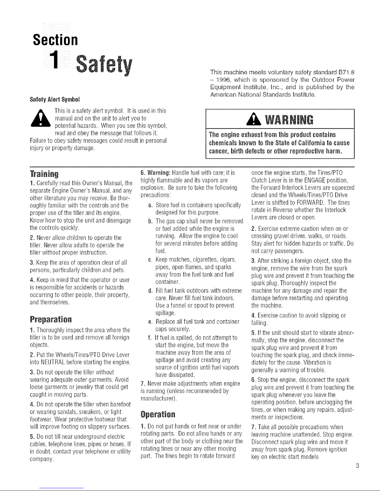
,_ This is asafetyalertsymbol. It is used inthis
Failureto obeysafety messagescould resultin personal
injury or property damage.
1. Carefullyreadthis Owner'sManual, the
separateEngineOwner's Manual,and any
other literature you mayreceive.Bethor-
oughly familiar with the controls and the
proper useof the tiller and itsengine.
Know how to stop the unit and disengage
the controls quickly.
2. Neverallow children to operatethe
tiller. Neverallow adults to operate the
tilier without proper instruction.
3.Keepthe areaof operation clearof alI
persons, particulariy chiidren and pets.
4, Keepin mind that the operator or user
is responsible for accidentsor hazards
occurring to other people,their property,
andthemselves.
1, Thoroughly inspect the areawhere the
tiller isto be usedand removealIforeign
objects.
2. Putthe Wheelsfrines/PTO Drive Lever
into NEUTRALbeforestarting the engine.
3. Do not operatethe tiiier without
wearingadequateoutergarments. Avoid
loose garments or jeweirythat could get
caught in moving parts.
4. Do not operatethe tiiier when barefoot
or wearingsandals, sneakers,or fight
footwear. Wear protective footwear that
wiii improve footing on slippery surfaces.
5, Do nottiii near underground electric
cabies,teiephoneiines, pipes or hoses. If
in doubt,contactyour telephoneor utility
company.
manuaiandonthe unit to alert youto
potential hazards. Whenyou seethis symbol,
readand obeythe messagethat foliows it.
6, Warning: Handlefue!with care;it is
highly flammable andits vaporsare
explosive. Besureto takethe following
precautions:
a. Storefue! incontainers specifically
designedfor this purpose.
b. The gascap shall never beremoved
or fue!addedwhiie the engine is
running. Allow the engineto cooI
for severalminutes before adding
fuel.
¢. Keepmatches,cigarettes, cigars,
pipes, openflames, and sparks
away from the fuettank and fueI
container.
d. FiiifueItankoutdoors with extreme
care. Neverfill fueI tank indoors.
Usea funnel orspout to prevent
spiiiage.
e. Replaceali fue!tank and container
caps securely.
f. If fuei isspiiied, do not attemptto
start the engine, but movethe
machineaway from the areaof
spiiiage and avoid creating any
source of ignition until fuel vapors
havedissipated.
7. Nevermakeadjustments whenengine
is running (unless recommendedby
manufacturer).
1. Donot put hands or feet nearor under
rotating parts. Donot aiiow handsor any
other part ofthe body or clothing nearthe
rotating tines or nearany other moving
part. Thetines beginto rotateforward
A
The engine exhaust from this productcontains
chemicals known to the State of California to cause
cancer, birth defects or other reproductive harm.
oncethe enginestarts, the Tines/PTO
Ciutch Leveris in the ENGAGEposition,
the Forward Interlock Leversare squeezed
closed and the Wheelsfrines/PTO Drive
Leveris shifted to FORWARD.Thetines
rotate in Reversewhether the Interlock
Leversare closed or open.
2. Exerciseextremecautionwhen on or
crossing graveldrives, walks, or roads.
Stayalert for hidden hazardsor traffic. Do
not carry passengers.
3. After striking a foreign object, stop the
engine, removethe wire from thespark
piug wire and prevent it from touching the
spark piug. ThorougHy inspect the
machinefor any damageand repair the
damagebefore restarting and operating
the machine.
4. Exercisecaution to avoid slipping or
falling.
5. If the unit should start to vibrate abhor-
marly,stopthe engine,disconnectthe
spark piugwire and prevent it from
touching the spark piug, andcheck imme-
diatelyfor the cause.Vibration is
generaiiyawarning of trouble.
6. Stopti_eengine,disconnectthe spark
piug wire and prevent it from touching the
spark piugwheneveryou ieavethe
operatingposition, before uncloggingthe
tines, or when makingany repairs, adjust-
ments or inspections.
7, Takeali possible precautions when
leavingmachineunattended.Stopengine.
Disconnectsparkplug wire andmoveit
away from spark piug. Removeignition
key on electdcstart models
Page 4
Section1: Safety
8. Beforecleaning,repairing, or inspect=
ing, stop the engineand makecertainatI
moving partshavestopped. Disconnect
the spark piug wire and prevent it from
touching the spark piug to prevent acci=
dentaIstarting.
9. The flap on thetine hood must be
down when operatingthe tiiier, unless
using the Hiiier/Furrowerattachment.
10. Neveruse the tiiier unlessproper
guards, piates,or other safetyprotective
devicesareinplace.
11. Do not run engine in an enclosed
area.Engineexhaustcontains carbon
monoxide gas, a deadlypoison that is
odorless, coloriess, and tasteless.
12. Keepchildren and pets away.
13. Neveroperate thetiiier underengine
power if the WheeISpeedLeveris inthe
FREEWHEELposition. In FREEWHEEL,
the wheels wiii not hold thetiiier backand
the revoiving tines could propei the tiiier
rapidly, possibtycausingioss of controi.
AIwaysengagethe WheetSpeedLever in
either FASTor SLOWposition before
starting the engineorengagingthetines
with the WheeIs/Tines/PTODrive Lever.
14. Be aware that the tiller may unexo
pectedlv bounce upward or jamp
forward ifthe tines should strike
extremely hard packedsoil, frozen
ground, or buried obstacles like large
stones, roots, or stumps, ff in doubt
about the tilling conditions,always use
the following operating precautions to
assist you in maintaining control of the
tiller:
a. Walk behind and to one side of the
tiller, using one handon the han-
dlebars. Relax your arm, bnt rise a
secnre handgrip.
b. Use shallower depth regulator
settings, working gradually deeper
with each pass.
c. Use slower wheel, tine and engine
speeds.
d. Clear the tilling area of all large
stones, roots and other debris.
e. Avoid using downward pressureon
handlebars.If need be, use slight
npward pressure to keep the tines
from digging too deeply.
f. Before contacting hard packedsoil
at the endof a row, reduce engine
speed and lift handlebarsto raise
tines out of the soil.
g. Jn an emergency, stoptines and
wheets byshifting the
WheelsiTinesiPTO Drive Lever
intoNEUTRAL.tf you can not
reach the leveror havelostcontrom
of the tiller, let go of the handle=
bars and aHcontroms,go not
attempt to restrain the tiller.
15. Donot overioadthe tiiier's capacity by
attempting to till too deeplyat too fast a
rate.
16. Neveroperatethe tiller at high
transport speedson hard or slippery
surfaces. Look behindandusecare when
backing up.
t7. Donot operatethetiiier on aslope
that istoo steep for safety. Whenon
slopes, slow down andmakesure you
havegood footing. Neverpermit the tiiier
to freewheel down slopes.
18. Neverallow bystandersnearthe unit.
19. Only useattachmentsandaccessories
that areapproved by the manufacturer of
the tiller.
28. Usetiiier attachments and acces-
sories when recommended.
21. Neveroperatethe tiller without good
visibility or iight.
22. Neveroperatethe tiiier if you are
tired, or underthe influence of alcohol,
drugs or medication.
23. Operatorsshali not tamper with the
engine-governor settings on the machine;
the governor controis the maximum safe
operatingspeedto protect the engineand
ali moving partsfrom damagecausedby
overspeed. Authorized service shail be
sought if a problemexists.
24. Donot touch engineparts which may
behot from operation. Letpartscool
downsufficiently.
25. POBON/OANGER--CAUSES
SEVEREBURNS.Thebattery on electric
start models contains suifudc acid. Avoid
contact with skin, eyesor clothing. Keep
out of reachof children.
Antidotes:
External- Flushimmediately with lots of
water.
Internal- Drink largequantities of water
or milk. Follow with milk of magnesia,
beateneggs orvegetableoil. Calla
doctor immediately.
Eyes- Fiushwith water for 15 minutes.
Getprompt medicai attention.
26. DANGER=BATTERIESPRODUCE
EXPLOSIVEGASES. Keepsparks, flame
or smoking materiaisaway. Ventilate
whencharging battery or using inan
enctosedspace. Alwayswear safety
goggteswhen working near battery.
27. Pieaseremember:Youcanalways
stop thetines and wheels by releasingati
controis, or by moving the ignition switch
and/orthrottle control lever on the engine
to OFFor STOP.
28. To ioador unloadthetiller, seethe
instructions in Section4 of this Manual.
29. Useextreme caution when backing or
puliing the machinetowards you.
30. Startthe engine carefuiiy according to
instructions and with feet well awayfrom
the tines.
31. Neverpick up or carry a machine
whiiethe engine is running.
32. When ioading or unioadingthe tiller,
alwaysdisengagetines andusesiower
wheelandenginethrottle speeds. Use
sturdy ramps wideandstrong enoughto
easiiysupport the tiiier (280-to-325 ibs.
dependingon model) and operator.
Nevergo down ramps in FORWARD
drive--the tiiier couid tip forward,
exposingyou to the tines (which should
be disengaged). Always useREVERSE
driveand backdown ramps. Togo up
ramps, use FORWARDdrive and follow
the tiller.
33, The ForwardInterlock SafetySystem
should betested for correct functioning
everytime the tiller or PTOpower unit is
used. SeeSection 4 in this Manual.
34. If using the optional DozerBlade,
either removethe tine attachment, or
disengagethe tines with the Tines/PTO
CiutchLever. Revolvingtines are
dangerous.
Page 5
Section1: Safety
Maintenance and Sterage
1. Keepthetiiier, attachments and acces-
sories insafeworking condition.
2. Checkali nuts, boits, andscrews at
frequent intervalsfor propertightness to
be surethe equipment is in safe working
condition.
3. Neverstore the tiiier with fue! inthe
fueJtank insidea buiiding where ignition
sources are presentsuch as hot water
and space heaters,furnaces, ciothes
dryers, stoves, electric motors, etc.).
Aiiow engine to cool beforestoring in any
encJosure.
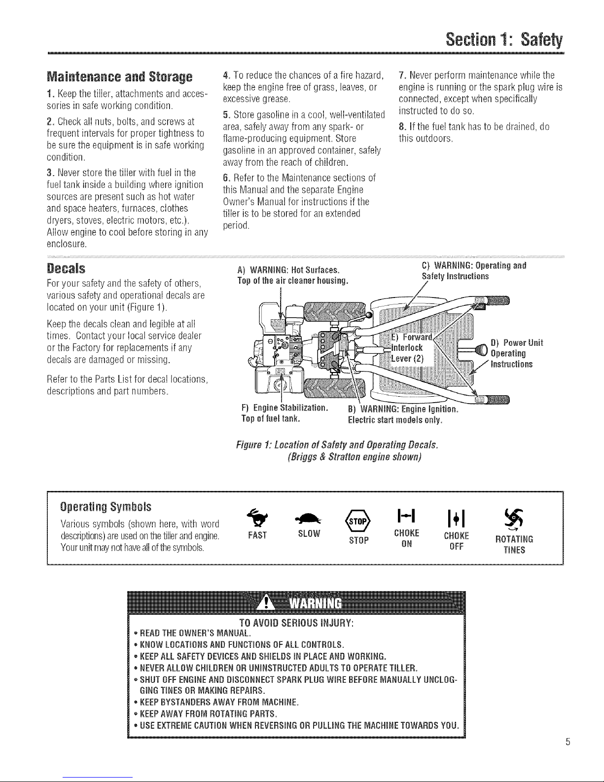
Deca_$ A) WARNmNG:HotSurfaces. C) WARNING:Operatingand
Foryour safetyand the safety of others, Tepeftheair umeanerheusing. Safetymnstruutiens
various safety and operationaldecalsare
located on your unit (Figure 1).
Keepthe decalscleanand legibleat all
times. Contactyour Iocai service dealer
or the Factoryfor repiacementsif any
decals are damagedor missing.
4. To reducethe chancesof a fire hazard,
keepthe enginefreeof grass, leaves, or
excessivegrease.
5. Storegasoiine in a cooi, weJi-ventiiated
area,safetyawayfrom any spark-or
flame-producing equipment. Store
gasolinein anapprovedcontainer, safeiy
awayfrom the reach of chiidren.
6. Referto the Maintenancesections of
this Manuaiandthe separate Engine
Owner's Manualfor instructions if the
tilier is to be stored for an extended
period.
7. Neverperform maintenancewhiiethe
engine is running or the spark piug wire is
connected,exceptwhen specifically
instructed to do so.
8, If the fuel tank hasto be drained, do
this outdoors.
Referto the PartsList for decallocations,
descriptions andpart numbers.
Operating Symbols
Varioussymbols (shown here,with word
descriptions)areusedonthetillerandengine=
Yourunitmaynot haveaiiofthesymbols=
oDEAD THEOWNER'SMANUAL.
KNOW LOCATmONSAND FUNCTmONSOFALLCONTHOLS.
*KEEPALLSAFETYDEVICESAND SHmELDSiNPLACEAND WORKmNG.
NEVERALLOW CHmLDRENOR UNBNSTRUCTEDADULTSTO OPERATETILLED.
*SHUT OFFENGINEAND DmSCONNECTSPARKPLUG WIHEBEFOREMANUALLYUNCLOG=
GiNGTINESOR MAKINGHEPAIRS.
- KEEPBYSTANDERSAWAYFROMMACHINE.
*KEEPAWAYFROM ROTATmNGPARTS.
USE EXTHEI_,_ECAUTmONWHEN HEVEHSmNGOH PULLINGTHEMACHINETOWARDS YOU.
Figure 1: Location of Safety and Operating Decals.
(Briggs & Stratten engine shown)
• @ H I÷1
CHOKE CHOKE HOTATING
FAST SLOW STOP ON OFF TmNES
TO AVOID SERIOUS INJURY:
Page 6
Section
To preventpersonal injury or property
damage, do not start the engine until
aJJ assembly steps are complete and
you have read and understand the
safety and operatinginstructionsinthis
manual
introduction
Carefuiiyfoiiow these assembiy steps to
correctly prepareyour tiiier for use. It is
recommendedthat you readthis Section
in its entirety beforebeginning assembly.
NOTE:Threedifferent Horse modeltiiiers
are covered in this Manual.Use oniythe
information applicableto your model.
Tiiier engines vary by model.Your engine
mayappear differently than thosefound
in illustrations of this manual.
inspect Unit
h_spectthe unit andcartonfor damage
immediately after deiivery. Contactthe
carrier (trucking company) if you find or
suspect damage. Inform them ofthe
damageandrequestinstructions for fiiing
a claim. To protect your rights, putyour
ciaim inwriting and maiIacopyto the
carrier within 15 days after the unit has
been delivered.Contact us atthe Factory
if you needassistanceinthis matter.
STEP1: Unpacking instructions
NOTE:Donot severelybend any ofthe
control cableson the unit.
1. The tiiier is heavy. Donot attemptto
removeit from tire shipping piatform until
instructed to do so in these Assembly
steps.
2. RemoveaiI ueassembtedparts from
the carton. Thehardware bag is included
in your literature packaging.
3. Checkthat you havethe items iisted
below (contact your local dealeror the
Factoryif any items are missing or
damaged).
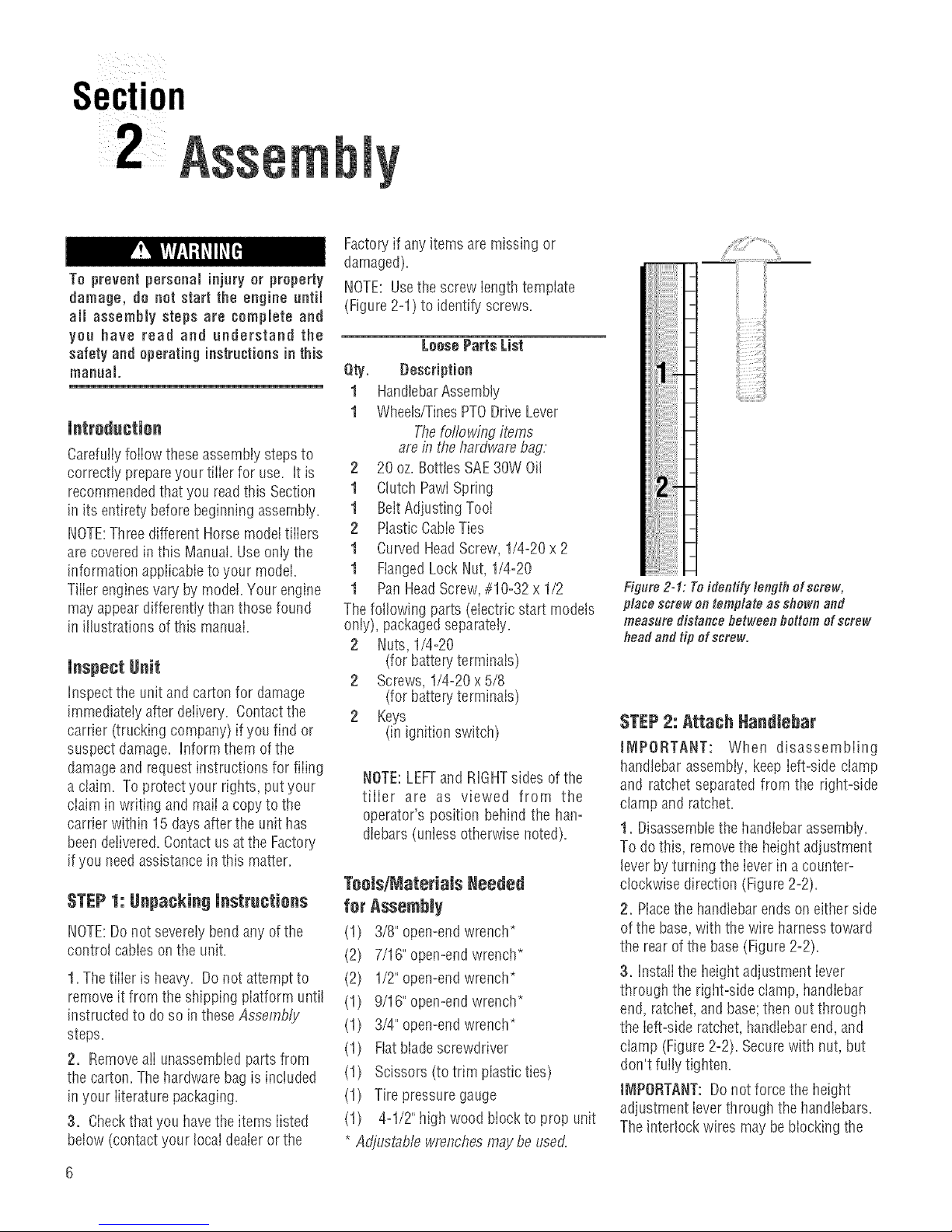
NOTE: Usethe screw iength template
(Figure2-1) to identify screws.
LoosePartsList
Qty. Bescription
1 HandlebarAssembly
1 Wheels/TinesPTODrive Lever
Thefor'towingitems
are in thehardware bag:
2 20 oz. BotttesSAE30W Oil
1 Clutch PawiSpring
1 BeltAdjustingTooI
2 PiasticCabieTies
1 Curved HeadScrew, 1/4-20 x 2
1 FlangedLock Nut, 1/4-20
1 PanHeadScrew,#10-32 x 1/2
The following parts (electric start models
only), packagedseparately.
2 Nuts, 1/4-20
(for battery terminals)
2 Screws, 1/4-20x5/8
(for battery terminals)
2 Keys
(in ignition switch)
NOTE:LEFTand RIGHTsides of the
tiller are as viewed from the
operator's position behind the han=
dlebars (unless otherwise noted).
Toels/MateriaJs Needed
for Assembly
(1) 3/8" open-endwrench*
(2) 7/16" open-endwrench*
(2) 1/2" open-endwrench*
(1) 9/16" open-endwrench*
(1) 3/4" open-endwrench*
(1) Fiatblade screwdriver
(1) Scissors (to trim plastic ties)
(1) Tire pressuregauge
(1) 4-1/2"high wood block to prop unit
* Adjustable wrenchesmaybeused.
Fi lure 2-1: Toidentify lengthof screw,
place screw on template as shown and
measure distance between bottom of screw
head andtip of screw.
STEP2: Attach Nandlebar
JNIPORTANT: When disassembling
handlebar assembly, keep ieft-side clamp
and ratchet separated from the right-side
clamp andratchet.
1. Disassemblethe handlebarassembly.
To do this, removethe heightadjustment
leverbyturning the ieverinacounter-
clockwise direction (Figure2=2).
2. Placethe handlebarends on either side
ofthe base,with the wire harnesstoward
the rearof the base(Figure2-2).
3. Instalithe heightadjustment iever
through the rigirt-side clamp, handlebar
end, ratchet,and base;then out through
the left-side ratchet,handlebarend,and
clamp (Figure2=2).Securewith nut, but
don't fully tighten.
t_IPORTANT: Do not force the height
adjustment ieverthrough the handlebars.
The interlock wires maybeblockingthe
Page 7
leverandcould bedamaged.You may
gentiy movethe wires aside if this
condition occurs.
4. Raisehandlebars to one of two height
settings andtiglrten the height adjustment
lever. Also, makesureali other mounting
hardware is securelytightened.
Left-Side
Clamp
and Nat
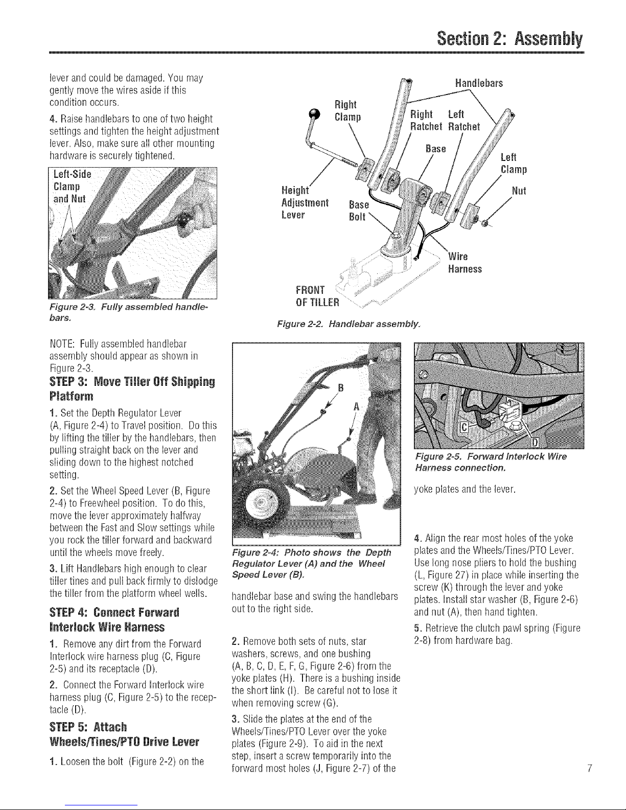
Figure 2=3. Fully assembled handle-
bars.
Section2: Assembly
Right
Clamp
Left
Clamp
Nat
Wire
Harness
FRONT
OFTILLER
Figure 2-2. Handlebar assembly.
NOTE:Fullyassembledhandlebar
assembly should appearas shown in
Figure2=3.
STEP3: Meve Tiller Off Shipping
Piatferm
1. Setthe DepthRegulator Lever
(A, Figure2=4)to Travelposition. Dothis
by lifting the tiiier bythe handiebars,then
puiiing straight back on the ievm and
siiding down to the highest notched
setting.
2. Setthe WheetSpeed Lever(B, Figure
2=4)to Freewheelposition. To do this,
movethe ieverapproximately halfway
betweenthe Fastand Siow settingswhiie
you rockthe tiiim forward andbackward
untilthe wheeis movefreely.
3. Lift Handlebarshigh enoughto ciear
tiiier tines and pull back firmty to dislodge
the tiller from the platform wheel wells.
STEP4: Cenneet Ferward
Figure2-4: Photo shows the Depth
Regulator Lever (A) and the Wheel
Speed Lever (B).
handIebarbaseand swing the handlebars
out to the dglrt side.
interlock Wire Harness
1. Removeany dirt from the Forward
Interlock wire harness plug (C, Figure
2=5)and its receptacle(D).
2. Connectthe ForwardIntmiock wire
harness plug (C,Figure2=5)to the recepo
tacle (D).
STEP5: Attach
Wheels/Tines/PT8 Drive Lever
1. Loosenthe bolt (Figure2=2)on the 7
2. Removeboth sets of nuts, star
washers, screws, and one bushing
(A, B, C, D, E,F,G, Figure2=6)from the
yoke piates (H). Thereis a bushing inside
the si_ortlink (i). Becarefuinot to loseit
when removing screw (G).
3. Siide the ptatesat the end of the
Wheeis/Tines/PTOLeveroverthe yoke
plates (Figure2-9). To aidin the next
step, insert ascrew temporarily into the
forward most holes (J, Figure2=7)of the
Figure 2=& Forward Interlock Wire
Harness connection.
yoke plates and the lever.
4. Align the rear most holes of theyoke
platesand the Wheets/Tines/PTOLever.
Uselong nosepiiers to hold the bushing
(L, Figure 27) in placewhile inserting the
screw (K) througtl the lever andyoke
plates.Install star wasller (B, Figure2=6)
and nut (A), then handtighten.
5. Retrievethe clutch pawl spring (Figure
2=8)from hardwarebag.
Page 8
Section2: Assembly
Removethe temporary screw (J, Figure
2=7)from the forward holes andmovethe
Wheelsffines/PTO Lever fuliy forward.
[nstalI the wider hook end of the dutch
pawt spring (M, Figure2=8)down into the
smaii holeatthe end of the handle. Use
piiers to insertthe other endinto the hole
in the long link bar (N).
NOTE:Do not bend or overstretch the
spring while instailing.
6. Pull the Wheets/Tines/PTOLeverback
to align the forward most holes (O,Figure
2=9)in the yoke plate with the holesin the
lever plates. Also align the bushing that is
insidethe short link bar (P). [nstalI the
screw, star washer, and nut, then tighten
securely.
Securelytighten all other hardware (Q,R,
Figure2=9). Also ensurethat the spring
(S) is properly seatedat both ends.
Completedassembly should appearas
illustrated in Figure2-9.
7. Test the operation of the
Wheets/Tines/PTOLever. Pushthe iever
down until it engagesinthe Forward
position. The clutch roller (T,Figure2o
10) must rest beneaththe adjustment
block (U). Next, movethe iever up to the
Neutral position. The clutch rolier (T,
Figure2=11)shouid reston the faceof the
adjustment block (U). To test Reverse,iift
and hoid the iever aii the way up in
Reverseposition, then iet it go. Thelever
should automaticaliy return to the Neutrai
position (Figure2=11). If not, do not use
the tiiier. Seeyour local authorized dealer
or carlthe FactoryTechnicalService
Departmentfor instructions.
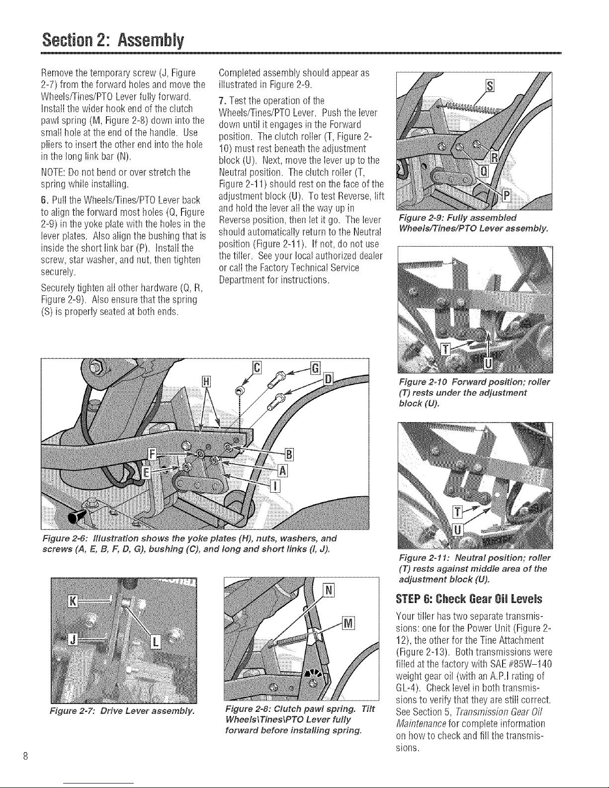
Figure 2-9: Fully assembled
Wheels/Tines/PTO Lever assembly.
Figure 2=6: Illustration shows the yoke plates (H), nuts, washers, and
screws (A, E, B, F, D, G), bushing (C), and long and short finks (t, J).
Figure 2=7: Drive Lever assembly.
Figure 2=8: Clutch pawl spring. Tilt
WheelslTineslPTO Lever fully
forward before installing spring.
Figure 2=10 Forward position; roller
(7")rests under the adjustment
block (U).
Figure 2=11: Neutral position; rofler
(T) rests against middle area of the
adjustment block (U).
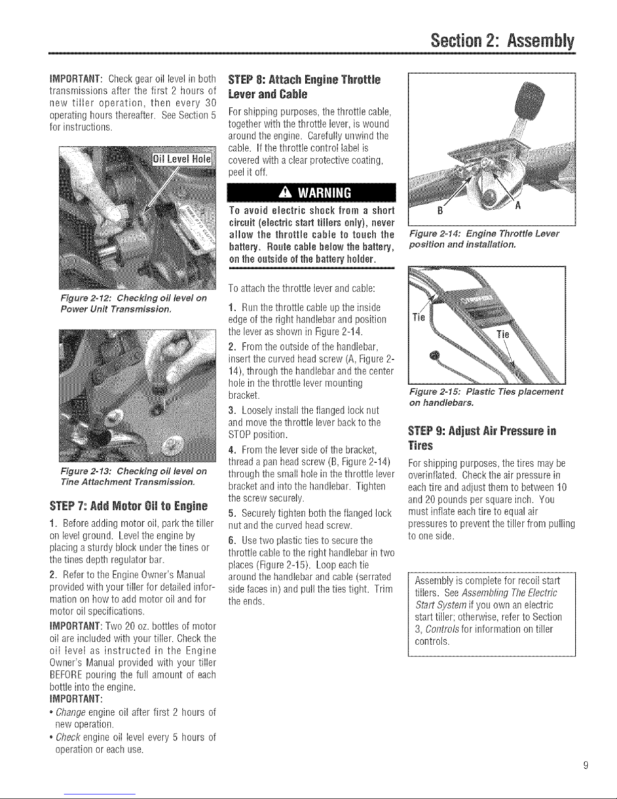
STEP6: CheckGearOil Levels
'four tiller hastwo separatetransmis=
sions: one for the PowerUnit (Figure 2-
12), the other for the TineAttachment
(Figure2-13). Bothtransmissions were
fiiied at the factory with SAE#85W-140
weight gear oil (withanA.PJ rating of
GU4). CheckieveIin both transmis-
sions to verify that theyarestiii correct.
SeeSection5, TransmissionGearOff
MaflTtenancefor compiete information
on howto checkandfill the transmiso
sions.
Page 9
Section2: Assembly
iMPORTANT: Checkgear oii ievet in both
transmissions after the first 2 hours of
new tiiier operation, then every 30
operating hours thereafter. SeeSection5
for instructions.
Figure 2=12: Checking oil level on
Power Unit Transmission.
Figure 2o13: Checking oil level on
Tine Attachment Transmission.
STEP7: Add Motor Oil to Engine
1. Beforeadding motor oii, park thetiller
oil ieveiground. Levelthe engine by
placing asturdy block underthetines or
the tines depth regulator bar.
2. Referto the EngineOwner's ManuaI
provided with your tiiier for detaiiedinfor-
mation onhow to add motor oil and for
motor oilspecifications.
IMPORTANT:Two 20 oz. bottles of motor
oii areincluded with your tiiier. Checkthe
oii ievei as instructed in the Engine
Owner's Manual provided with your tiiier
BEFOREpouring the full amount of each
bottle into the engine.
iMPORTANT:
° Changeengine oil after first 2 hours of
new operation.
. Checkengine oii ieve! every 5 hours of
operation or each use.
STEP8: Attach Engiee Throttle
Lever and Cable
Forshipping purposes,the throttie cabie,
together with the throttie iever, is wound
around the engine. Carefuiiyunwind the
cable. If the throttle controi iabetis
covered with aclearprotective coating,
peel it off.
To avoid electric shock from a short
circait (electric start tiJJers only), never
allow the throttle cabte to roach the
battery. Route cabte below the battery,
on the outside of the batteryholder.
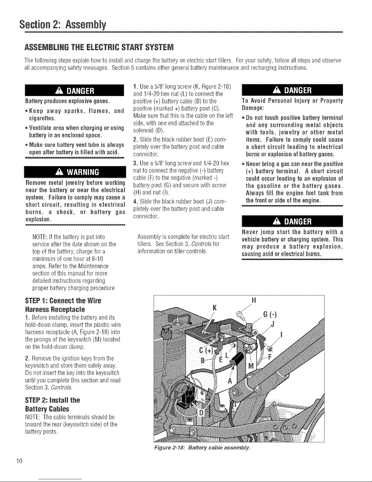
To attach thethrottle leverand cable:
1. Runthe throttle cableupthe inside
edge of the right handlebarand position
the lever as shown in Figure2=14.
2. Fromthe outside of the handlebar,
insert the curved headscrew (A,Figure2=
14),through the handlebarand the center
hole in thethrottie levermounting
bracket.
3. Loosely instaii the flanged iocknut
and movethe throttle leverbacktothe
STOPposition.
4. Fromthe leverside of the bracket,
thread a pall headscrew (B, Figure 2=14)
through the smaiihoiein the throttle iever
bracket and into the handlebar. Tighten
the screw securely.
5. Secureiytighten both theflanged lock
nut and the curvedheadscrew.
6. Usetwo plastic tiesto securethe
throttle cableto the right handlebar intwo
places (Figure2=15). Loop eachtie
around the handlebar and cable (serrated
side faces in) andpulIthe ties tight. Trim
the ends.
f} A
Figure 2-14: Engine Throttle Lever
position and installation.
Figure 2o15: Plastic Ties placement
on handlebars.
STEP9: Adjust Air Pressurein
Tires
Forshipping purposes,the tires maybe
overinflated. Checkthe air pressure in
eachtire and adjust themto between10
and 20pounds per squareinch. You
must inflate each tire to equalair
pressuresto prevent thetiller from pulling
to one side.
Assembiy is compiete for recoiistart
tiilers. SeeAssembling TheElectric
Start System if you own an electric
start tiller; otherwise, refer to Section
3, Controlsfor information oil tiller
controls.
Page 10
Section2: Assembly
ASSEMBLINGTHE ELECTRICSTARTSYSTEM
ThefoiiowJngsteps expiaiu howto Jnstaliandchargethe battery on electrJcstart tJiiers. Foryour safety',foliow alisteps and observe
all accompanying safety messages=Section5 contains other generalbattep/maintenance and recharginginstructions=
1. Usea 5/8" long screw (K, Figure2=18)
and 1/4=20hexnut (L)to connectthe
Battery producesexplosive gases.
++Keep away sparks, flames, and
cigarettes.
++Ventilate area when chargingor using
battery in an enclosed space.
®Make sure battery vent tube is always
openafter battery is filled with acid.
Remove metal jewemrybefore working
near the battery or near the electrical
system. Failure to comply may cause a
short circuit, resulting in emectfical
burns, a shock, or battery gas
explosion.
positive (+) battery cabte(B)to the
positive (marked +) battery post (C).
Makesurethatthis is the cabie on the left
side, with oneend attachedto the
solenoid (D).
2. Slidethe black rubberboot (E)corn=
pietely overthe batterypost and cable
connector.
3. Usea 5/8" iong screwand 1/4=20hex
nut to connectthe negative(-) battep/
cable (F)to the negative (marked-)
batte_' post (G) andsecurewith screw
(H)andnut (I)=
4. Slidethe black rubberboot (J) corn=
pietetyoverthe battery post and cable
connector.
To Avoid Personal tnjury or Property
Damage:
+Do not touch positivebattery terminal
and any surrounding metal objects
with tools, jewelry or other metai
items. Failure to comply could cause
a short circuit leading to electrical
burns or explosion of battery gases.
++Never bring a gas can near the positive
(+) battery terminal. A short circuit
could occur leading to an explosion of
the gasoline or the battery gases.
Always fill the engine fuel tank from
the front or side of the engine.
NOTE:Ifthe battery is put into
serviceafterthe dateshown on the
top ofthe battery,charge for a
minimum of onehourat 6=10
amps. Referto the Maintenence
section of this manualfor more
detailedinstructions regarding
proper batterycharging procedure
STEP1: Connect the Wire
Harness Beeeptacie
t. Beforeinstaiiing the batteryand its
hold-down clamp, insertthe plastic wire
harness receptacle(A,Figure2-18)into
the prongs of the keyswitch (M) located
on the hoW-downctamp.
2. Removethe ignition keysfrom the
keyswitch and store themsafelyaway.
Donot insert the keyinto the keyswitch
untiiyou compietethis section and read
Section 3, Contro/s.
STEP2: install the
Battery Cables
NOTE:The cableterminals should be
toward the rear (keyswitch side) of the
battery posts.
Assembly is complete for electric start
tiliers. SeeSection 3, Controlsfor
information on tiller controls.
Never jump start the battery with a
vehiclebattery or chargingsystem. This
may produce a battery explosion,
causing acid orelectrical burns.
10
Figure 2o18: Battery cable assembly.
Page 11
Section
3 =ea u
Before operating your machine,
¢arefuJJy read and understand aJJ
safety, controls, operating instructions
in this Manual, the separate Engine
Owner's Manual and on the decals on
the machine.
Failure to fellow these instructionscan
result inseriuus persunalinjury.
Jntreduetion
This section describes the location and
function of the controls andfeatures on
your tiiier. Referto Section 4, Operation
for detaiiedoperating instructions.
Practiceusingthese controis, with the
engine shut off, untiiyou completely
understandthe operation ofthe controls
and feelconfident with eachof them.
iMPORTANT:Referto the separateengine
manufacturer's Engine Owner's Manuai
for information about the controls on the
engine.
NOTE:Aiireferencesto ieft,right, front
and rearof the machineare basedon a
position behindthe handiebarsandfacing
forward.
PTO Attachments Feature
In addition to powerful tiiiing capabiiity,
you can quickly convert your machine
into a PTO(PowerTake=Off)PowerUnit
that is capable of towing or powering
various TROY-BILTattachments,
You canaccessthis capabiiity by
removing the tines attachment (powered
bythe PTOPower Unit). The PTOPower
Unit isthen avaiiabtefor enginepowered
attachments,or for puiiing ortowing non-
poweredattachments. SeeSection 4,
PTOPower Unitfor detaiiedinformation
on instaiiingand operatingTROY-BILT
PTOattachments.
Wheelo/TiueoiPTODrive Lever
Usethe VVheets/Tines/PTODrive Lever (A,
Figure3-1) to engageand disengage
powerto thetransmission.
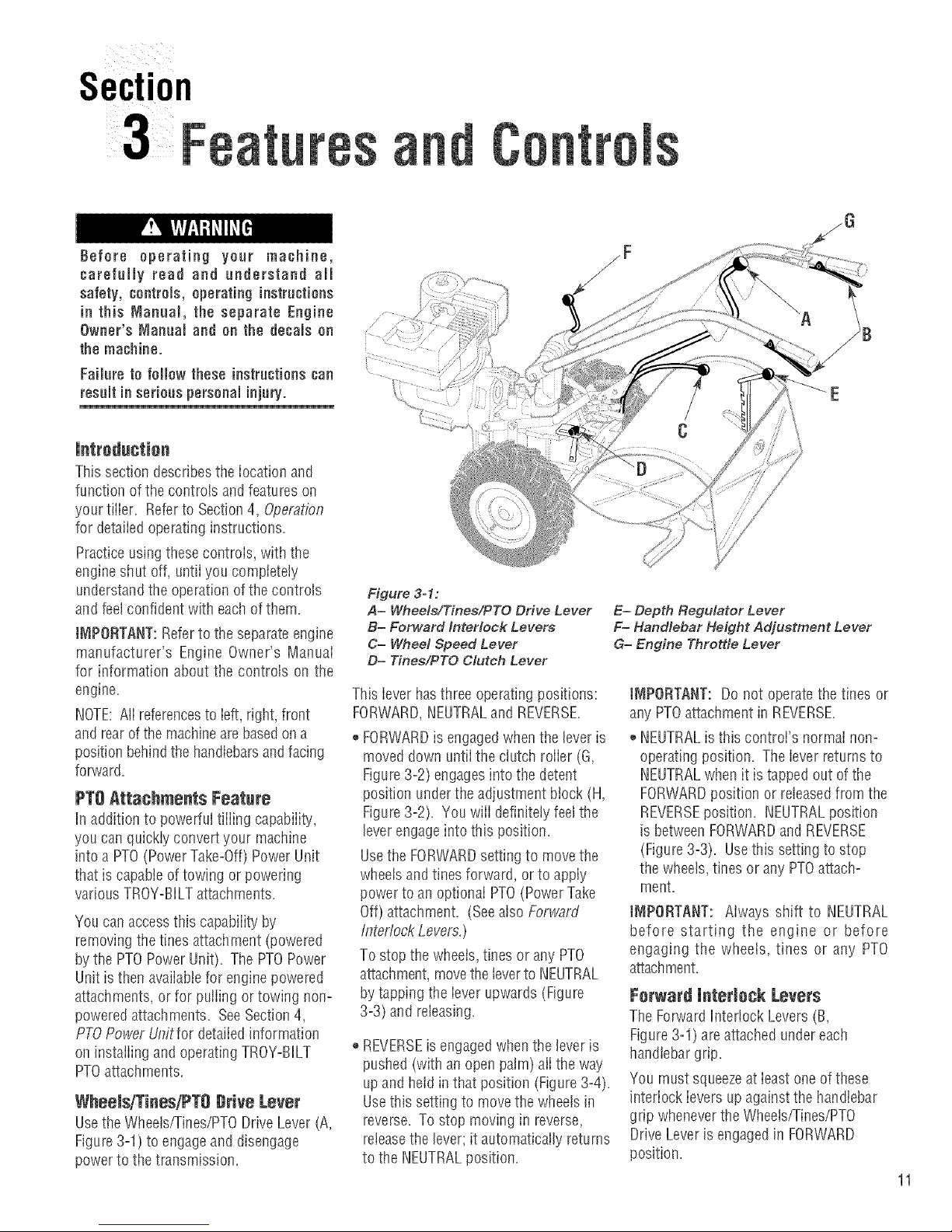
Figure 3-1:
A= Whee/s/Tinee/PTO Drive Lever
B= Forward Interlock Levers
C= Wheel Speed Lever
D= Tines/PTO Clutch Lever
This lever has three operating positions:
FORWARD,NEUTRALand REVERSE.
,, FORWARDis engagedwhenthe leveris
moved down untilthe clutch roller (G,
Figure3-2) engagesinto the detent
position underthe adjustment block (H,
Figure3-2). You wilI definitely feelthe
leverengageinto this position.
Usethe FORWARDsetting to movethe
wheels andtines forward, or to apply
power to an optional PTO(Power Take
Off) attachment. (Seealso Forward
Interlock Levers.)
To stop the wheeis,tines or any PTO
attachment,movethe Ieverto NEUTRAL
by tapping the iever upwards(Figure
3=3)and releasing.
REVERSEis engagedwhenthe lever is
pushed (with an open palm) aiithe way
up and heid inthat position (Figure 3-4).
Usethis setting to movethe wheetsin
reverse. To stop moving in reverse,
reteasethe lever; it automatically returns
to the NEUTRALposition.
/F
E= Depth Regulator Lever
F= Handlebar Height Adjustment Lever
G= Engine Throtde Lever
JNIPOflTANT: Do not operatethe tines or
any PTOattachment in REVERSE.
NEUTRALis this control's normai non-
operating position. Theiever returns to
NEUTRALwhen it is tappedout of the
FORWARDposition or releasedfrom the
REVERSEposition. NEUTRALposition
is betweenFORWARDandREVERSE
(Figure3-3). Usethis setting to stop
the wheels, tines orany PTOattach-
ment.
IMPORTANT: Always shift to NEUTRAL
before starting the engine or before
engaging the wheels, tines or any PTO
attachment.
Forward interlock Levers
The Forward h_ter!ockLevers(B,
Figure3-1) areattached undereach
handlebargrip.
You must squeezeat ieastoneof these
interlock ievers up against the handlebar
grip wheneverthe Wheets/Tines/PTO
Drive Leveris engagedin FORWARD
position.
11
Page 12
Section3: FeaturesandControls
Yer!fy Pos!tion of Clutch Roller
When you sNft between FORWABDI
NEUTRAL and REVERSEI the clutch
roller at the base of the
Wheeb!Tines/PTO Drive Lever should
be pesitiobed as shown in Eigures3_2,
3:3 and 3'4, Verify the position Ofthe
clutch roller as you shift the bver_ If it
is not POSitbnedcorrect!y, contact the
Faptory or see your local authorized Wheel Speed Lever
dealer.
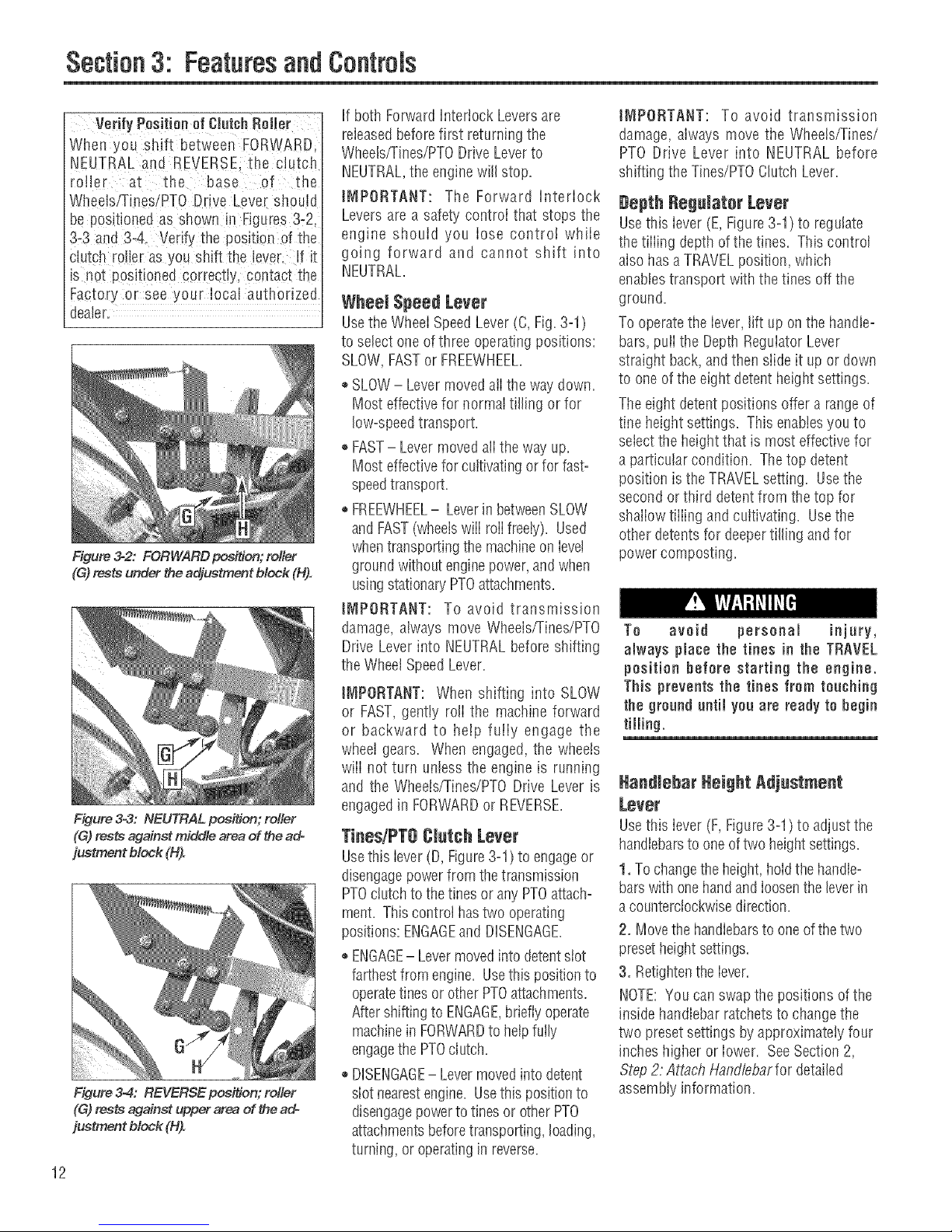
Figure 32: FORWARD pos_on; rotier
(G)rests under the adjustment block (H).
Figure 3-3: NEUTRAL position; relier
(G) rests against middle area of the ado
justment block (H).
Figure 3-4: REVERSE position; relier
(G) rests against upper area of the ad-
justment block (H).
12
If both Forward Interlock Leversare
releasedbefore first returning the
Wheels/rines/PTO Drive Leverto
NEUTRAL,the enginewill stop.
iMPORTANT: The Forward Interlock
Levers are a safety control that stops the
engine should you lose control while
going forward and cannot shift into
NEUTRAL.
Usethe Wheel SpeedLever(C,Fig.3-1)
to select oneofthree operatingpositions:
SLOW,FASTor FREEWHEEL.
* SLOW- LevermovedalIthe waydown.
Most effective for normal tilling or for
low-speedtransport.
®FAST- Lever moved all the way up.
Most effective for cultivating or for fast-
speedtransport.
FREEWHEEL- Leverin betweenSLOW
and FAST(wheelswill rollfreely). Used
whentransporting the machineonlevel
ground withoutenginepower,andwhen
usingstationaryPTOattachments.
IMPORTANT: To avoid transmission
damage, always move Wheels/Tines/PTO
Drive Lever into NEUTRALbefore shifting
the Wheel SpeedLever.
IMPORTANT: When shifting into SLOW
or FAST,gently roll the machine forward
or backward to help fully engage the
wheel gears. When engaged, the wheels
will not turn unless the engine is running
and the Wheets/Tines/PTODrive Lever is
engagedin FORWARDor REVERSE.
TinesiPT8 CJutchLever
Usethis lever(D, Figure3-1) to engageor
disengagepowerfrom thetransmission
PTOclutchto the tines or any PTOattach-
ment. Thiscontrol has two operating
positions: ENGAGEand DISENGAGE.
ENGAGE- Levermovedinto detentstot
farthestfrom engine. Usethis positionto
operatetinesor other PTOattachments.
Aftershifting to ENGAGE,brieflyoperate
machinein FORWARDto helpfully
engagethe PTOclutch.
,, DISENGAGE- Levermovedinto detent
slot nearestengine. Usethis positionto
disengagepowerto tines or otherPTO
attachmentsbeforetransporting, loading,
turning, or operatinginreverse.
IMPORTANT: To avoid transmission
damage, always move the Wheels/Tines/
PTO Drive Lever into NEUTRAL before
shifting the Tines/PTOClutch Lever.
#epth Regalater Lever
Usethis lever (E, Figure3-1) to regulate
the tiiiing depthof the tines. This control
alsohasa TRAVELposition, which
enablestransport withthe tines off the
ground.
To operate the lever, rift up on the handle-
bars, pulIthe DepthRegulatorLever
straight back, and then slide it up or down
to one of the eight detent height settings.
The eight detentpositions offer a rangeof
tine heightsettings. This enabbs you to
selectthe heightthat is most effectivefor
a particular condition. The top detent
position isthe TRAVELsetting. Usethe
second or third detent from the top for
shallow tilling and cultivating. Usethe
other @tents for deepertilling and for
powercomposting.
To avoid personal injury,
always place the tines in the TRAVEL
position before starting the engine.
This preventsthe tines from touching
the gronnd nntil yon are ready to begin
tilling.
Handlebar Height Adjustment
Lever
Usethis lever (F, Figure3-1) to adjustthe
handlebarsto oneoftwo heightsettings.
1, To changethe height, hoidthehandb-
barswithonehandandioosenthe leverin
acounterclockwisedirection.
2. Movethe handiebarsto oneofthe two
presetheightsettings.
3. Retightentheiever.
NOTE:Youcan swapthe positions of the
insidehandlebarratchetsto changethe
two presetsettings by approximately four
inches higiler or iower. SeeSection2,
Step2: Attach Handfebarfor detailed
assembly information.
Page 13
The tiller handlebars can be swung out
300to the right side for use only with the
PTOChipper/Shredder attachment. This
is done by looseningthe mounting bott
on the handlebar base, Never operate
your tiller or attachments, otherthan the
PTOChipper/Shredder, with the handleo
bars in the right side position. Doing so
could result in unsafe handling and
personalinjury.
Engine Throttle Lever
Usethe throttle lever(G, Figure3-1)to
adjust engine speedaswell asto start
and stop the engine.
Movethe leveraway from the STOP
position before starting the engine.
Enginespeedsare variableand range
betweenthe FASTandSLOW. Usethe
STOPposition to turn the engine off.
NOTE:A secondarythrottle leveris
located on the front ofthe 8HPandIOHP
engines. AseparateOn/Offswitch may
alsobeavailableontheengine. (See
EngineOwner'sManualfor information.)
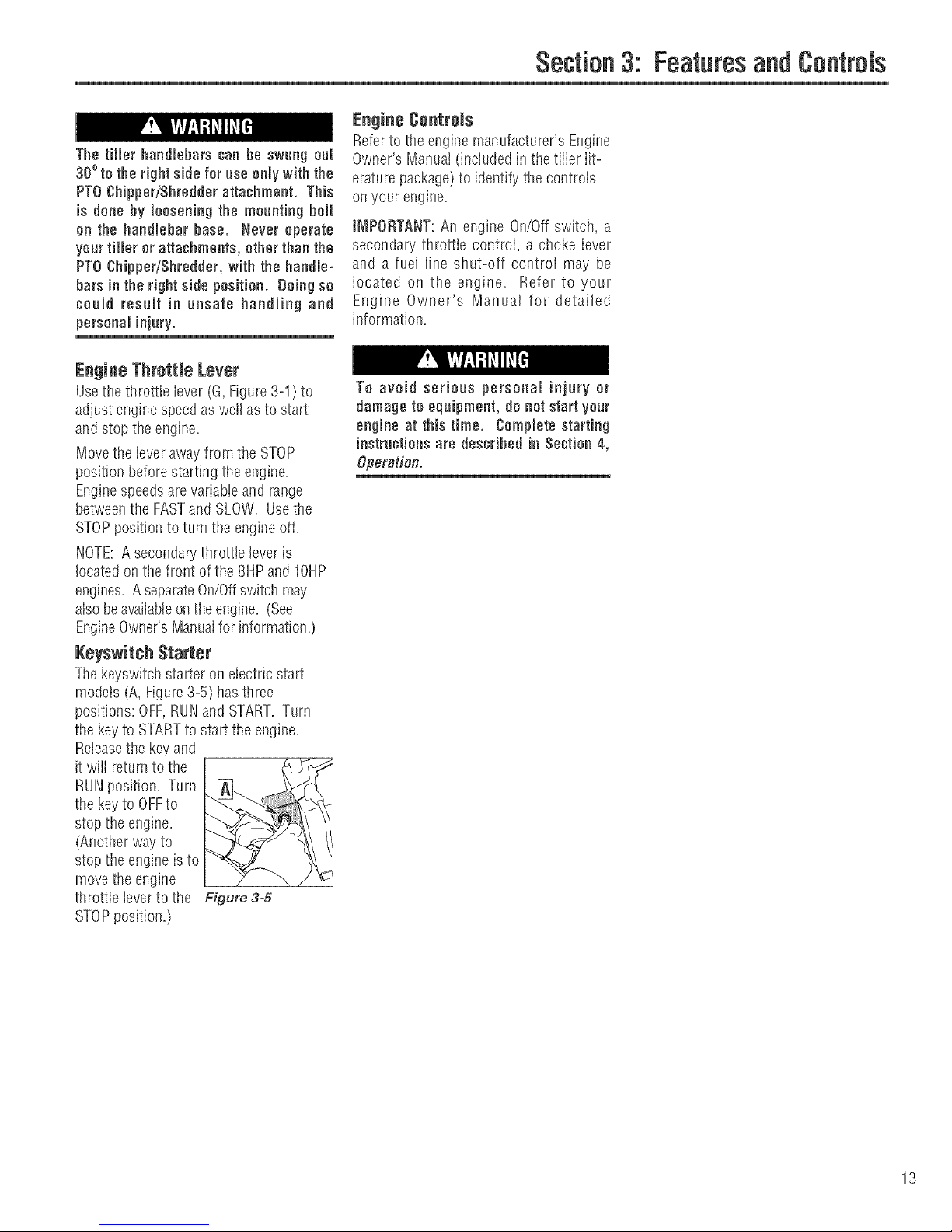
Keyswitch Starter
Thekeyswitchstarter on electricstart
models (A, Figure3-5) hasthree
positions: OFF,RUNand START. Turn
the keyto STARTto start the engine.
Releasethe keyand
it wilI returnto the
RUNposition. Turn
the keyto OFFto
stop the engine,
(Another way to
stop the engine is to
move the engine
throttle leverto the Figure 3-5
STOPposition,)
Section3: FeaturesandControls
Engine Controls
Referto the enginemanufacturer's Engine
Owner's Manual (included in thetiller lit-
erature package)to identify the controls
on your engine.
IMPORTANT:An engine On/Offswitch, a
secondary throttle control, a choke lever
and a fue! iine shut-off controi may be
located on the engine, Refer to your
Engine Owner's Manual for detailed
information.
To avoid serioae personal injury or
damage to equipment, do not start your
engine at this time. Complete starting
instructionsare desoNbed in Section 4,
Operation.
13
Page 14
Section
Before operating your machine,
carefullyread and understand all safety
(Section 1), ¢ontrots (Section 3) and
operating instrnotions (Section 4) in
this Manual, in the separate Engine
Owner's Manual and on the deoamson
themachine.
FaUnre to follow these instructionscan
resnlt inserious personaminjury,
Readthis Section ofthe manual
thoroughiy beforeyou start the engine.
Then,take the timeto famiiiarizeyourself
with the basic operation of the tilbr
before using it in your garden. Findan
open, level areaand practice usingthe
tiibr controis without the tines engaging
the soii (put tines in Travelsetting--
Section 3, Depth RegulatorLeve,9. Onty
after you've becomecompieteiy famiiiar
with the tflier shoutd you begin using it in
the garden.
Your tiller and its optional PTO Power
Unit attachments are capable of
oansingsefions injury to nntrained or
carelessoperators.
To avoid serious personal injury or
property damage, read the Owner's
Manual that is provided with any
optionaJ accessories or attachments
before using the tiller or PTO Power
Unit.
Break-in i)peration
Perform the following maintenanceduring
the first hours of newoperation (see
MaflTtenanceSectionin this Manuaiand
maintenanceinformation in the Engine
Owner's Manuai).
1, Changeengineoii after first 2 hours of
newengineoperation.
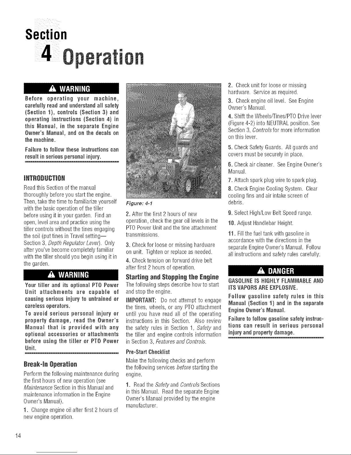
Figure: 4=1
2. After the first 2 hours of new
operation,checkthe gear oiI levelsinthe
PTOPower Unit and the tine attachment
transmissions.
3. Checkfor loose or missing hardware
on unit. Tighten or replaceasneeded.
4. Checktension on forward drivebelt
after first 2 hours of operation.
Starting and Stopping the Engine
Thefollowing stepsdescribehow to start
and stop the engine.
IMPORTANT: Do not attempt to engage
the tines, wheels, or any PTOattachment
untii you have read ali of the operating
instructions in this Section. Atso review
the safety rubs in Section 1, Safety and
the tiller and engine controls information
in Section 3, Featuresand Controls.
Pro=StartChecklist
Makethe following checks and perform
the following services beforestarting the
engine.
1. Readthe Safetyand Confl'otsSections
inthis Manual Readthe separate Engine
Owner'sManuai provided by the engine
manufacturer.
2, Check unit for looseor missing
hardware. Serviceas required.
3, Checkengine oil level. SeeEngine
Owner's Manual.
4. Shift the Wheeis/Tines/PTODriveiever
(Figure4-2) into NEUTRALposition. See
Section3, Controls for more information
on this iever.
5, Check Safety'Guards. AIIguards and
covers must besecurelyin place.
6, Check air cieaner. SeeEngineOwner's
Manual.
7. Attach sparkpiug wire to spark piug.
8, Check EngineCooling System. Clear
cooiing fins and air intakescreen of
debris.
g. Sebct High/Low Belt Speedrange.
10. Adjust HandlebarHeight.
11, FilIthe fuettank with gasolinein
accordancewith the directions in the
separateEngineOwner's Manual. Foliow
alIinstructions andsafetyrules carefully.
GASOUNEIS HIGHLY FLANJNIABLEAND
iTS VAPORSAREE×PLOSIVE.
Follow gasoline safety rules in this
Manual (Section 1) and in the separate
EngineOwner's N_annaJ.
Failure to folJow gasoline safety instruc-
tions can resuJt in serious personal
injnryandproperty damage.
14
Page 15
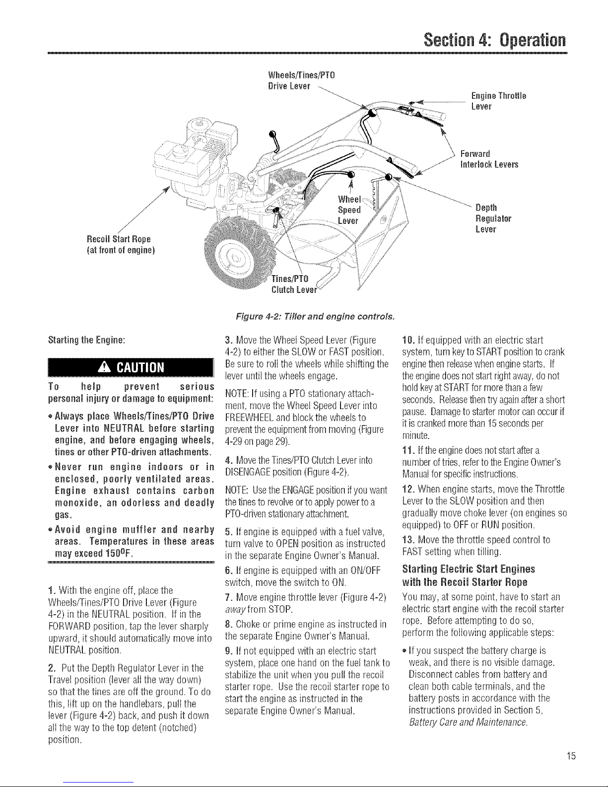
Figure 4-2: Tiller and engine controls.
Section4: Operation
EngineThrottle
Lever
Forward
interlockLevers
Depth
RegaJatar
Lever
Starting the Engine:
To help prevent serious
personalinjuryor damage to equipment:
,_Always place Wheels/Tines/PTO[}rive
Lever into NEUTRAL before starting
engine, and before engaging wheels,
tines orether PTO=dfivenattachments.
,,Never run engine indoors or in
enclosed, poorly ventihted areas.
Engine exhaust contains carbon
monoxide, an odorless and deadly
gas,
,,Avoid engine muffler and nearby
areas. Temperatares in these areas
may exceed150OF.
1. With the engineoff, placethe
Wheets/Tines/PTODrive Lever (Figure
4=2)in the NEUTRALposition. If in the
FORWARDposition, tap the iever sharply
upward, it should automatically move into
NEUTRALposition.
2. Putthe DepthRegulator Leverinthe
Travel position (leveralI the way down)
so that the tines areoffthe ground. To do
this, lift up on the handlebars,pulI the
lever (Figure 4-2) back,and push it down
ali the way to the top detent (notched)
position.
3. Movethe WheelSpeedLever(Figure
4=2)to either theSLOWor FASTposition.
Besureto rolithe wheelswhiie shifting the
leveruntil thewheelsengage.
NOTE:If usingaPTOstationaryattach°
meet,movethe WheelSpeedLeverinto
FREEWHEELandblock the wheelsto
preventthe equipmentfrom moving(Figure
4=29onpage29).
4. MovetheTines/PTOClutchLeverinto
DISENGAGEposition(Figure4=2).
NOTE:UsetheENGAGEpositionifyou want
thetinesto revolveor to applypowerto a
PTO=ddvenstationap./attachment.
5. If engine is equippedwith a fuel valve,
turn valveto OPENposition as instructed
in the separateEngineOwner'sManual.
6. If engine is equippedwith an ON/OFF
switch, move the switchto ON.
7. Moveengine throttie lever (Figure4=2)
away from STOP.
8. Chokeor prime engineasinstructed in
the separateEngineOwner's Manual.
9. If not equippedwith an electric start
system, placeone hand on the fueltankto
stabiiizethe unitwhen you pu!I the recoii
starter rope. Usethe recoii starter ropeto
start the engineasinstructed in the
separateEngineOwner's Manual.
10. If equipped with an electric start
system, turnkeyto STARTpositionto crank
enginethenreleasewhenenginestarts. If
theenginedoesnotstart rightaway,donot
holdkeyatSTARTfor morethana few
seconds. Releasethentry againafterashort
pause. Damageto startermotorcan occurif
itiscrankedmorethan15secondsper
minute.
11. Ifthe enginedoesnotstart aftera
numberoftries,refertotheEngineOwner's
Manualforspecificinstructions.
12. When engine starts, movetheThrottle
Leverto the SLOWposition andthen
graduatiy movechoke iever (onenginesso
equipped) to OFFor RUN position.
13. Movethe throttle speedcontrol to
FASTsetting whentilling.
Starting Electric Start Engines
with the Re€ell Starter Repe
You may,at some point, haveto start an
etectric start engine with the recoii starter
rope. Beforeattemptingto do so,
perform the foiiowing appiicabiesteps:
®Ifyoususpectthe battery chargeis
weak,andthere is no visible damage.
Disconnectcabtes from batteryand
cieanboth cableterminais, and the
batten' posts in accordancewith the
instructions providedin Section5,
BatteryCareand Maintenance.
15
Page 16
Section4: Operation
Reconnectthe cables and securely
tighten to battery posts. Theenginewiii
rechargethe battery if the battery is still
good.
o If you suspectthe batteris "dead", or if
the batteryis damaged, disconnect,and
remove it. Haveit checkedby a
quaIifiedtechnician.
®If battery hasbeen removed,wrap cable
terminals at endof positive cable with
electricaItapeandsecurethe cableto
the batterybracket.Thiswill prevent
electricaldischarge.
Beforepuffingthe recoil starter rope,
turn the keyswitchto the RUN position.
Move theThrottle Leverawayfrom
STOPposition andset the choke as
applicable.See EngineOwner's Manual.
Cold Weather Operation
Whentemperaturesfail below40% eo
the following s_ensto protectyour
engine ana transmission from _amage:
1. Referto the EngineOwner's Manual
for motor oil specifications for cold
weather operation. Usewinter blend
gasoline
2. Warm up the enginebefore putting it
undera load.
3. Usewinter-blenDgasoline,
4. Usethe correct weight gearoil in PTO
PowerUnit[ransmission.
5. Warm up thetransmission c2earoil as
follows: With engine running, moye
Wheel SpeedLever(Figure4-2) to
FREEWHEEL_thenblock wheelssothey
can't roll, put Tines/PTOClutch Le/or
into DISENBAGE.then squeezeone of
the ForwardInterlock Leversandsnift
the Wheels!Tines!PTODrive Leverto
FORWARD.
6. if wheelsarefrozen to the grounD,
melt ice with warm water.
Stepping the Engine and Tiller
1. Tostop the wheels andtines, movethe
Wheets/Tines/PTODrive Lever into
NEUTRALposition andthen releaseboth
ForwardInterlock Levers.
16
2. Move the engineThrottle Leverto the
STOPposition. Thenonelectric start
models,turn the keyto OFF. Removethe
keyfor safekeeping.
NOTE:Theengine may havea separate
Throttle Control LeverandON/OFFswitch
onthe engine. Thesecontrols can also be
usedto stopthe engine. Seethe Engine
Owner'smanuai for information specific
to your engine.
Operating the Tiller
Whenfirst practicing, keepthe Tines/PTO
CiutchLeverin DISENGAGEposition and
the Wheel SpeedLeverin SLOWposition.
To avoid serious personal injury or
damage to equipment:
,_Always placeWheelsiTiees/PTO Drive
Lever in NEUTRAL before starting
engine, and before engaging wheels,
tines orother PTOattachments.
®Be sure there are no obstacles behind
you before moving inreverse.
* Wheels/TinesiPTO Drive Lever should
automatically return to NEUTRAL
when released from REVERSE
position, tf it does not, move lever to
NEUTRAL manually and discontinue
use until you adjust the lever. See
Seotion 5, Checking and Adjustind
Reverse Drive System.
,,No reverse motion should occur if
Wheels[TinesiPTO Drive Lever is not
held up in REVERSE. See Section 5,
Checkiflg and Adjustind Reverse
Drive System for adjustment steps.
Do not use tiller unless properly
adjusted.
,, Always return to NEUTRALand let all
motion stop before shifting to
FORWARDor REVERSE.
Thefoiiowing pagesprovideguidelines
for using your tiiier effectively and safely
in various gardening applications. Be
sure to readTf/ling Tips& Techniques,in
this Section, beforeyou actually putthe
tines into the soii.
This isa traditional standard=rotating-tine
(SRT)tiiier with forward rotating tines. It
operatesin a compietely different manner
than counter-rotating-tine (CRT)tillers, or
from front-fine tillers.
lVleving the Tiller Forward and Tilling
1. Start the engineandgraduatiyincrease
enginespeedto FAST(seeStarting the
Engine,this Section).
The Forward Interlock Safety System is
designed for the operator'ssafety. Do
not disoonneot or attempt to defeat the
purpose of the system, if the system
malfunctions, immediatelycontactyour
IDeal authorized dealer or the
TROY=BtLTTeohnical Service Depart =
meet for assistance. Do not use the
tiller or the PTO power unit until the
Forward hterlook Safety System is
functioning properly. Always test the
system before asing the tiller or PTO
power anit.
2. Test the Forward Interlock Safety
System. See TestingForward interlock
System,this Section.
Keep away from rotating tines. Rotating
tines will caase injury.
3. When practicing,setthe Depth
Regulator Leverto Travelposition.
Otherwise,set the DepthRegulatorLever
to a desireddepth.
4. MoveTines/PTOClutchLever to
ENGAGEposition if you wantthetines to
turn. If practicing, leavein DISENGAGE.
tNIPORTANT: Do not move Tines/PTO
Ciutch Lever to ENGAGE unless
Wheels/Tines/PTO Drive Lever is in
NEUTRAL Tiller damagemayoccur!
5. To movethe tiller forward andengage
the tines, squeezeand hold eitherForward
Interlock Lever(Figure4-3) against the
handlebargrip, then movethe
Wheels/Tines/PTODrive Leverdown to
FORWARDposition.
Page 17
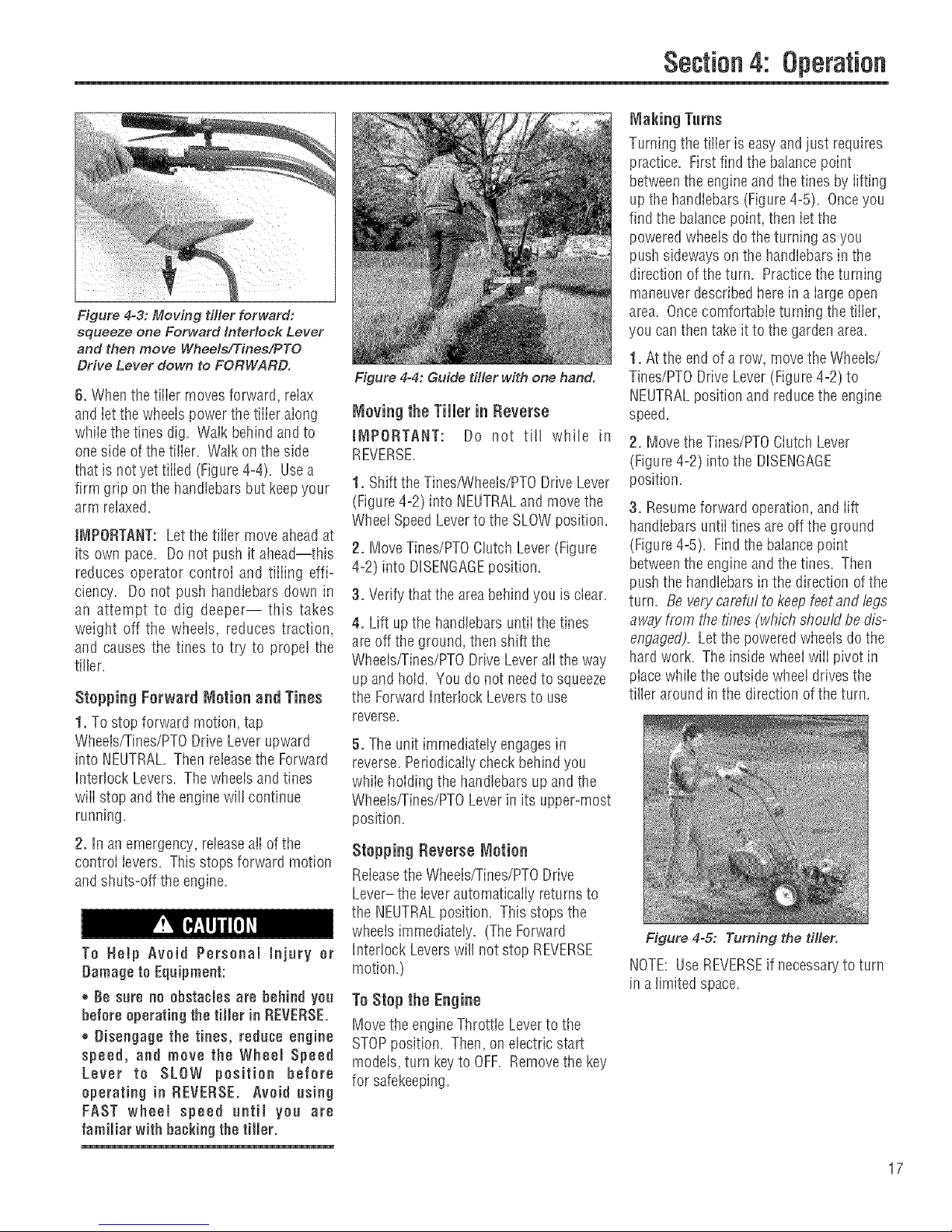
Figure 4=3: Moving tiller forward:
squeeze one Forward interlock Lever
and then move Wheels/Tines/PTO
Drive Lever down to FORWARD.
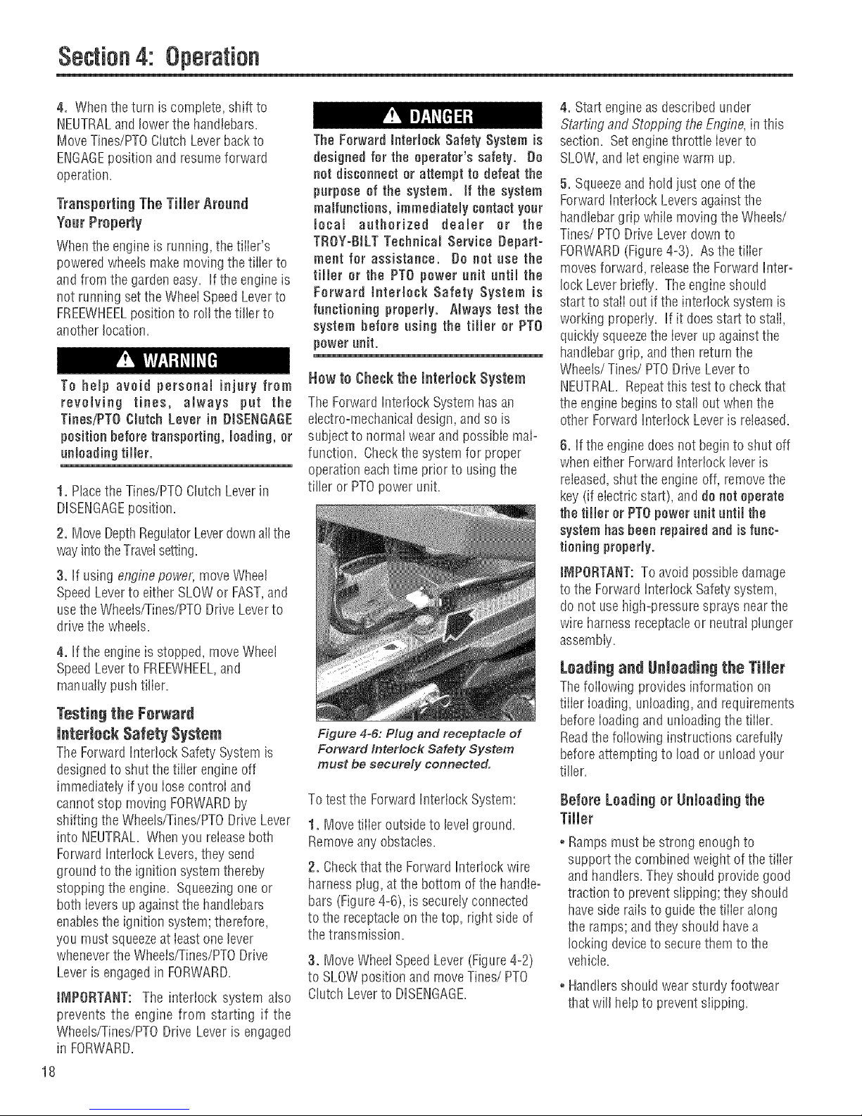
6. Whenthetiller movesforward, reiax
and ietthe wheels power the tiiier along
whiie the tines dig. Walk behind andto
one side of the tifler. Watkonthe side
that is notyettilled (Figure4-4). Usea
firm grip on the handlebarsbut keepyour
arm relaxed,
JNtPORTANT:Letthe tiiier move aheadat
its own pace. Do not push it ahead--this
reduces operator controi and tiiiing effi=
ciency. Do not push handlebarsdown in
an attempt to dig deeper-- this takes
weigilt off the wheels, reduces traction,
and causes the tines to try to propel the
tiller.
Stopping Forward Motion and Tines
1. To stop forward motion, tap
Wheels/Tines/PTODriveLeverupward
into NEUTRAL.Then releasethe Forward
Interlock Levers. Thewheelsandtines
wiii stop and the enginewill continue
running.
2. in an emergency, reieaseaiI of the
controi ievers. This stops forward motion
and shuts-off the engine.
To Help Avoid Personal injury or
Damage to Equipment:
®Be sure no obstacles are behind you
before operatingthe tiller in REVERSE.
® Disengage the tines, reduce engine
speed, and move the Wheel Speed
Lever to SLOW position before
operating in REVERSE. Avoid using
FAST wheel speed until you are
familiar with backing the tiller.
1
Figure 4=4: Guide tMer with one hand.
Moving the Tiller in Reverse
tN_PORTANT: Do not till while in
REVERSE,
1. Shift the Tines/Wheels/PTODrive Lever
(Figure4=2)into NEUTRALand movethe
WheetSpeedLever to the SLOWposition.
2. Move Tines/PTOClutch Lever(Figure
4-2) into DISENGAGEposition.
3. Verify that the areabehindyou is clear.
4. Lift upthe handlebarsuntii tile tines
are off theground, thenshift the
Wheeisffines/PTO Drive Lever aii the way
up andhoW. Youdo not needto squeeze
the Forward Interlock Leversto use
reverse.
5. Theunit immediatelyengages in
reverse.Periodicaliycheckbehind you
whiie hewing the handlebarsupandthe
Wheelsfrines/PTO Leverin its upper-most
position.
Stopping Reverse Motion
Releasethe Wheels/Tines/PTODrive
Lever- the ieverautomaticaiiy returnsto
the NEUTRALposition. Thisstops tile
wheeis immediately. (The Forward
Interlock Leverswill not stop REVERSE
motion.)
To Stop the Engine
Move the engineThrottleLeverto the
STOPposition. Then,on electric start
models, turn keyto OFF. Removethe key
for safekeeping.
Section4: Operation
Making Turns
Turningthe tiiier is easyand just requires
practice. First find the balancepoint
betweenthe engineandthe tines by iifting
up the handlebars (Figure4°5). Onceyou
find the balancepoint, then iet the
poweredwheets dothe turning as you
push sideways on the handlebarsin the
direction of the turn. Practicetheturning
maneuverdescribed herein a iarge open
area. Oncecomfortabie turning the tiiier,
you can then take it to the gardenarea.
1. Atthe end of a row, movethe Wheeis/
Tines/PTODrive Lever(Figure4-2) to
NEUTRALposition and reducethe engine
speed.
2. Movethe Tines/PTOClutch Lever
(Figure4-2) into the DISENGAGE
position.
3, Resumeforward operation,andlift
handlebars until tinesareoffthe ground
(Figure4°5). Find the balancepoint
betweentile engine andthe tines. Then
push the handlebarsin the direction of the
turn. Be vely camfuf to keep feet and legs
away from the fines (which should be dis°
engaged). Letthe poweredwheelsdothe
hard work. The inside wheelwiii pivot in
placewhiie the outside wheei drivesthe
tifler around inthe direction ofthe turn.
Figure 4-5: Turning the tiller.
NOTE:UseREVERSEif necessaryto turn
in alimited space.
17
Page 18
Section4:
4. When the turn is complete, shift to
NEUTRALand lower the handlebars=
Move Tines/PTOCiutcil Leverbackto
ENGAGEposition and resumeforward
operation.
Transporting The Tiller Around
Year Property
Whenthe engine is running, thetiiieSs
poweredwheatsmake moving the tiiier to
and from the gardeneasy. If the engineis
not running set the WheelSpeedLeverto
FREEWHEELposition to roll thetiller to
another location.
To help avoid personal injury from
revolving tines, always pat the
TinesiPTOCtutsh Lever in DISENGAGE
position before transporting, loading,or
unloading tiller.
1. Placethe Tines/PTOClutch Leverin
DISENGAGEposition.
2. MoveDepthRegulatorLeverdownalI the
wayintotheTravelsetting.
3. If using engine powel; move Wheel
SpeedLeverto either SLOWor FAST,and
usethe Wheeis/Tinee/PTODrive Leverto
drivethe wheats.
4. If the engineis stopped, move Wheel
SpeedLeverto FREEWHEEL,and
manually pushtiller.
Tenting the Forward
lnterinsk Safety System
TheForwardInterlock Safety System is
designedto shut the tiiier engineoff
immediately if you iosecontroi and
cannot stop moving FORWARDby
shifting theWheets/Tines/PTODriveLever
into NEUTRAL=Whenyou releaseboth
Forward Interiock Levers,they send
ground to the ignition systemthereby
stopping the engine. Squeezingone or
both ievers up against the handlebars
enabiesthe ignition system; therefore,
you must squeezeat ieast one lever
wheneverthe Wheeis/Tines/PTODrive
Leveris engagedin FORWARD=
iNIPORTANT: The interlock system aiso
prevents the engine from starting if the
Wheets/Tines/PTODrive Lever is engaged
in FORWARD.
18
The Forward Interlock Safety System is
designed for the operator's safety. De
net dissonnect or attempt to defeat the
purpose of the system, if the system
maJfnnetions, immediatelycontactyour
local anthorized dealer or the
TROY=BtLTTeshnisal Service Depart =
meet for assistance. Do not use the
filler or the PTO power unit until the
Forward hterlesk Safety System is
functioning properly. Always test the
system before using the tiller or PTO
powerunit.
How to Cheek the interlock System
The Forward Interlock System has an
electro=mechanicaldesign,and so is
subject to normal wearandpossible mat=
function. Checkthe system for proper
operationeachtime prior to usingthe
tiller or PTOpower unit.
Figure 4-6: Plug and receptacle of
Forward Interlock Safety System
must be securely connected.
To test the Forward Interlock System:
1. Movetiller outside to levelground.
Removeany obstacles.
2. Checkthat the Forward Interlock wire
harnessplug, at the bottom of the handle°
bars (Figure4°6), is securely connected
to the receptacieon the top, right side of
the transmission.
3. Move WheeiSpeedLever(Figure4=2)
to SLOWposition and moveTines/PTO
Clutch Leverto DISENGAGE.
4. Start engine as describedunder
Starting and Stopping theEngine,in this
section. Setenginethrottle ieverto
SLOW,and iet enginewarm up.
5. Squeezeand holdjust oneof the
ForwardInterlock Leversagainst tire
handlebargrip while moving the Wheels/
Tines/PTO DriveLeverdown to
FORWARD(Figure4-3). Asthe tiiier
movesforward, releasethe Forward Inter°
lock Leverbriefly. Theengineshould
start to staiiout if the interiock system is
working properly. If it doesstart to stali,
quickiysqueezethe iever up against the
handlebargrip, and then return the
Wheels/Tines/PTO Drive Leverto
NEUTRAL.Repeatthis test to checkthat
the engine begins to stail out when the
other ForwardInterlock Lever is released.
6. If the engine does not begin to shut off
when either ForwardInterlocklever is
released,shut the engine off, removethe
key (if electric start), anddenet operate
the tiller or PTOpower unit until the
system has beenrepaired and isfuns=
tioning properly.
IMPORTANT:Toavoid possible damage
to the ForwardInterlock Safetysystem,
do not use high=pressuresprays nearthe
wire harness receptacleor neutrai plunger
assembly.
Loading and gnlnading the Tiiiet
Thefollowing provides information on
tiiier ioading, unloading, and requirements
beforeioadingand unloadingthe tiiier.
Readthe foiiowing instructions carefuliy
beforeattemptingto loador unloadyour
tiller.
Before Leading or Unloading the
Tiller
° Rampsmust bestrong enoughto
support the combined weight of the tiiier
and handlers.They should provide good
traction to preventslipping;they should
haveside raiisto guidethetiiier along
the ramps; andthey shouid have a
locking deviceto securethemto the
vehicle.
° Handlersshould wear sturdy footwear
that will help to preventslipping.
Page 19
Section4: Operation
oTurn the vehicle'sengineoff and apply
its parking brake.
o Positionthe ioading vehicie so that the
rampangieis asflat as possibie (the
less inclineto the ramp, the better).
Leading the Tiller
1. Use ioading ramps that arestrong and
wide enough to safely hold the weight of
the tiiier andthe operator combined--
your tiller weighs between280 and 325
Ibs,
2. Move theTines/PTOClutch Lever
(Figure4-2) into DISENGAGEposition.
3. Setthe Depth Regulator iever(Figure
4-2) to the Travelposition.
4. Move WheelSpeedLever (Figure4-2)
into SLOWposition and reducethe
enginethrottle speed.
5. Sisiftthe Wheelsfrines/PTO Lever
(Figure4-2) into FORWARDposition and
foiiow the tiiier upthe ramps (Figure4-7).
Checkthe wheelsasyou movethe tiiier
forward. Ensurethat they move up the
center of each ramp.
6. Preventtiiier from roiiing in vehicie.
LeaveWheei SpeedLeverin FASTor
SLOWposition, chock wheels with blocks
and tie down the tiller.
Figure 4=7: To go up ramps, use
unmeadingthe Tiller
iMPORTANT:fgeverunloadtire tiiier in
FORWARDdrive, Thetiiier couid tip
forward andexposeyou to the tines
(which shouid be disengagedas
instructed).
1. Use loading ramps that arestrong and
wide enough to safely hotdtire weight of
the tiller andthe operator combined--
your tiller weigirs between280 and 325
Ibs.
2. Movethe Tines/PT0 Ciutch Lever
(Figure4-2) to DISENGAGEposition.
3. Setthe DepthRegulator Lever (Figure
4-2) to the Travelposition.
4. MoveWheel SpeedLever (Figure4-2)
to SLOWposition and reducethe engine
throttle speed.
IMPORTANT: Look behind you before
you back down the rampto ensurethat ali
is clear. Whiie descending,keepchecking
for obstacies behindyou.
5. Moveand hold tire Wheets/Tines/PTO
Leverinto REVERSEdrive and backdown
the ramps (Figure4°8). Checkthe wheets
asyou movethe tiiier backward. Ensure
that they movedown the centerof each
ramp.
Figure 4-8: To go down ramps, use
REVERSE drive.
Changing Speed Brits
Your tiller hastwo belt-drivenspeed
ranges- HIGH RANGEandLOWRANGE
- you pick one or the other by deciding
which setof pulleygrooves to movethe
forward beltinto. By moving the belt
from onespeed rangeinto the other, in
combination with the FASTand SLOW
wheelspeeds,you obtain a choice of four
different forward wheel speedsand two
different tine speeds.
To help avoid serioas personal injary,
stop the engine, remove the ignition
key, disconnect spark plug wire and
move the wire away from the spark
plug, and let engine and muffler cod
down before changing belt speeds.
Changingthe belt from LOWrangeinto
HIGHrange (or backagain) is a matter of
moving the belt from oneset of puliey
grooves to asecond set of pulleygrooves.
This changeis done quickiy and without
tools (Figures4-9 through 4-13).
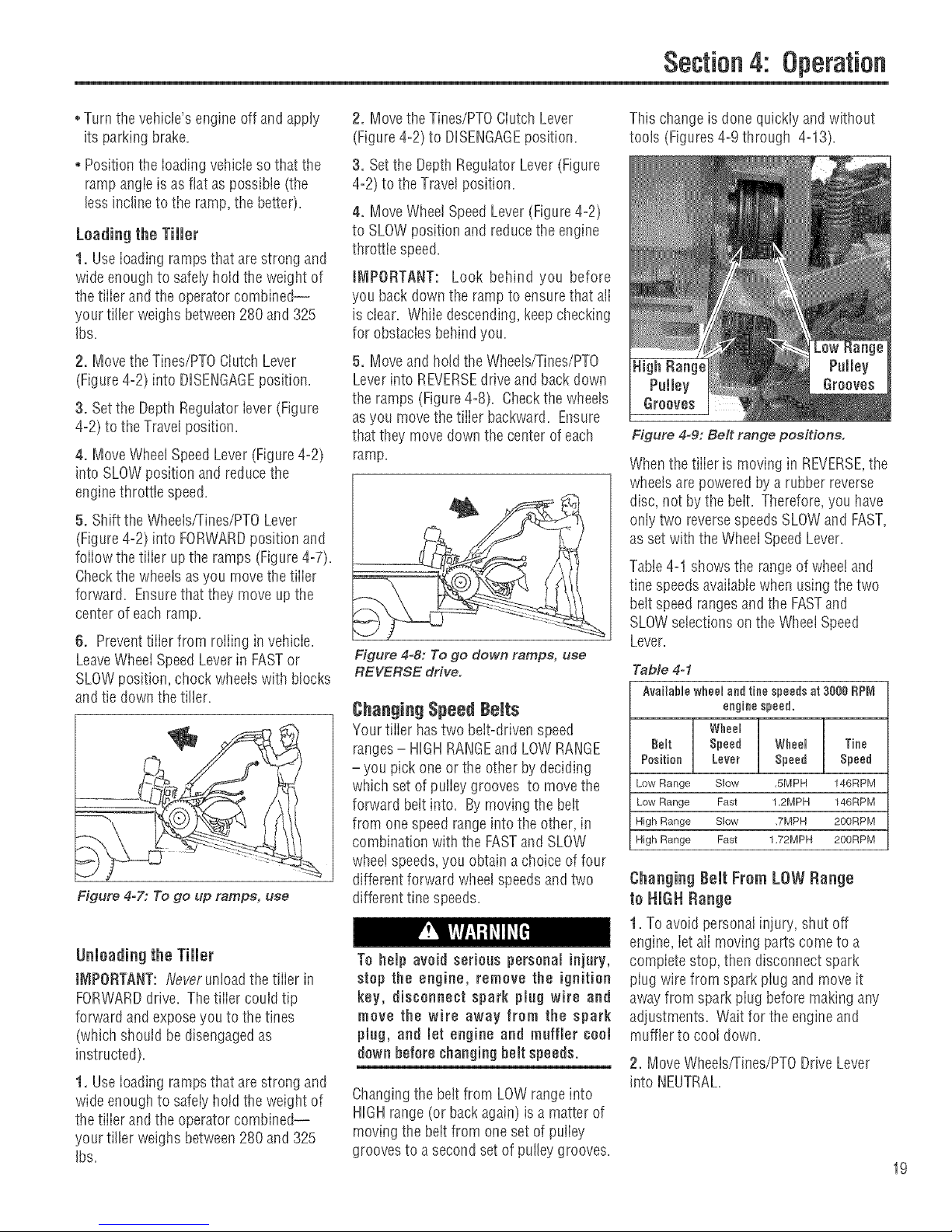
Figure 4=9: Belt range positions.
Whenthe tiller is moving in REVERSE,the
wheels are powered by a rubberreverse
disc, not by the belt. Therefore, you have
onlytwo reversespeedsSLOWand FAST,
as set with the WheelSpeedLever.
Table4-1 shows the range of wheeiand
tine speeds availablewhen usingthe two
bdt speed rangesand the FASTand
SLOWselections onthe WheelSpeed
Lever.
Table 4-1
Available wheel and tine speeds at 3888 RP_
engine speed.
Wheel
Belt Speed Wheel Tine
Position Lever Speed Speed
Low Range Slow ,5MPH 146RPM
Low Range Fast 12MPH 146RPM
High Range Slow ,7MPH 200RPM
High Range Fast 1,72MPH 200RPM
Changing Belt From LOW Range
in HIGH Range
1. To avoid personalinjury, shut off
engine, iet alimoving partscometo a
compiete stop, then disconnect spark
piug wire from spark piug and move it
away from spark piug before making any
adjustments. Wait for the engineand
muffler to cooIdown.
2. Move Wheels,rrines/PTODrive Lever
into NEUTRAL.
19
Page 20
Section4: Operation
The HiGH speed belt range position
combined with a FAST wheel speed
setting propels the tiller at the fastest
pace. Reduce the enginethrottle speed
when starting outto help avoid personal
injury or propertydamage if using this
speed combination.
3. Kneelon fefiside of tiller. To create
beit slack, reachoverto right side ofthe
pulieys and push in atthe center of the
beit with a finger. At the sametime, use
your ieft hand to work the belt part=way
onto the iower=fronttransmission pulley
groove (Figure 4=10).
4. Goto right sideof tiller and finish
seatingthe beit.
5. Stiil holding the iever up in REVERSE
position, and working from the ieft side of
thetiiier, move the beit from the lower=
front transmission grooveto the lower-
reartransmission groove.
6. Goto the right side of the tiiier and
finish seatingthe belt (Figure4-13).
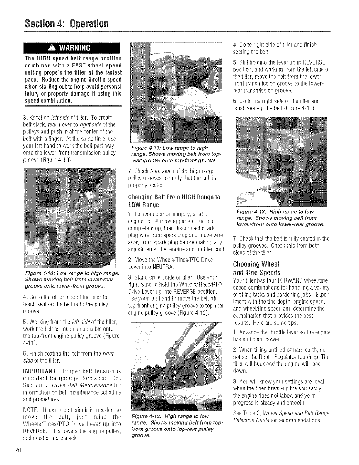
Figure 4-11: Low range to high
range. Shows moving belt from top=
rear groove onto top-front groove.
7. Checkboth sides of the high range
puiiey grooves to verify that the belt is
properly seated.
Changing Belt Frem HiGH Range te
LOW Range
1. To avoid personal injury,shut off
engine,iet aii movingparts cometo a
complete stop, then disconnect spark
plug wire from spark piug and movewire
away from sparkpiug before making any
adjustments. Letengineand muffler cool.
2. Move the Wheels/Tines/PTODrive
Leverinto NEUTRAL.
Figure 4o10: Low range to high range.
Shows moving belt from lower-rear
groove onto IowerWront groove.
3. Standon Ieftside of tiiier. Useyour
right handto holdthe Wheels/Tines/PTO
Drive Leverupinto REVERSEposition.
4. Goto the other side ofthe tilier to Useyour ieft handto movethe belt off
finish seatingthe belt onto the putley top-front enginepuiiey groovetotop-rear
groove, engine pulleygroove (Figure4-12).
5. Working from the left sideof the tiller, _ ::::
work the bett as muchaspossibie onto
thetop-front enginepulley groove (Figure
4-11).
6. Finish seatingthe beltfrom the right
sideof thetiller.
JNIPORTANT: Proper beittension is
important for good performance. See
Section 5, Drive Belt Maintenance for
information on belt maintenance schedule
and procedures.
NOTE: If extra belt slack is needed to
move the belt, just raise the
Wheels/Tines/PTO Drive Lever up into
REVERSE.This iowers the engine puiley,
and createsmore slack.
Figure 4-12: High range to low
range. Shows moving belt from top-
front groove onto top-rear pulley
groove.
Figure 4-13: High range to low
range. Shows moving belt from
Iowet=front onto Io wet-rear groo re.
7. Checkthat the bett is fully seatedin the
pulley grooves. Checkthis from both
sides of the tiiier.
Choosing Wheel
and TineSpeeds
Your tilier hasfour FORWARDwheei/tine
speedcombinationsfor handling avariety
of tiiiing tasksandgardeningjobs. Exper-
iment withthe fine depth, enginespeed,
and wheel/finespeedand determine the
combination that provides the best
results. Hereare some tips:
1. Advancethe throttle leverso the engine
hassufficient power.
2. Whentiffing untiiied or hard earth, do
not set the DepthRegulatortoo deep.The
tiiier will buckandthe engine will load
down.
3. You will know your settings areideal
whenthe tines break-upthe soil easily,
the enginedoes not iabor, andyour
progress is steadyandsmooth.
SeeTable2, Wbee/Speedand BettRange
Se/ectionGuidefor recommendations.
2O
Page 21

Section4: Operation
TABLE2..4: WHEELSPEEDANDBELT RANGE
!MpORTANT_ For COrre_twheel speed and be!t range _hoiees when es!ng attachments m' accessories
ether than tinee, read the OwneriOperater t_lanual previdedwith the altochment er aeee_sery,
SLOWGEAR,LOWBELTRANGE
For:
,,Tilling insod,
oTilling inhardclay'.
oTilling understandingcorn°
stalks intoughsoil conditions.
oTilling undercovercrops.
o Preparinga deepseedbed.
oTilling instony soil.
oTilling underresiduesand
organicmatter.
Mixing in fertilizers,manure.
SLOWGEAR,NIGHBELTRANGE
For:
oTilling insod or hardclay.
oTilling understandingcorn°
stalks(slow,steadyspeed
allowstime toshredstalks).
oTilling undercovercrops
(bestwheelspeedandbelt
speedrangeill most soils).
oPreparingseedbeds(best
speedchoicein mostsoils).
oTilling instony ground.
oBuildingraisedgardenbeds.
oMixing infertilizer.
oUsinghiller wings in hard
soil.
oMixingfertilizer and manure.
oTilling residuesandorganics.
Let the tiller do the work
oWhiietiffing, relaxand iet the wheeis
puli the tiiier alongwhiie thetines do
the digging. Waik on the side that is not
yet finished (to avoid making footprints
in tire freshly tiffedsoii) and iightly, but
securelygrip the handlebarwith just
one hand (Figure4°4).
oAvoid pushing down on the handlebars
in an attempt to force the tiiier to dig
deeper. Doingso takesthe weight off
the poweredwheeis,causing them to
losetraction. Without thewheels
helping to hoid thetiiim back,the tines
wiii attempt to propeithe tiiier - often
causingthe tiiier to skip rapidly across
the ground. (Sometimes, slight
downward pressure on the handlebars
will helpget through a particularly
tough section of sod or unbroken
ground, but in most casesthis won't be
eecessa%)
TilliRg depths
oAvoid flying to dig too deeply too
quickly, especiallywhen busting sod or
tilling soil that hasn't beentilled for
some time. Useehaliow depthsettings
(only an inch or two deep) for the first
passesthrough the gardenarea.
FASTGEAR,LOWBELTRANGE
For:
oGoingover seedbedfor the
lasttime beforeplantingcrops.
oCoveringoverseedsill wide
rowor plot planting(lift hall°
dlebarsto avoidgoing tee
deep).
oHillingandfurrowing,
oMaking raisedbeds.
oCultivating(lift handlebarsto
avoidgoing too deep).
oTilling largeareas.
oTillingorganicmatter in.
oCultivatingbetweenraised
bedswith optional
hiller/furrowerattachment.
iques
With eachsucceeding pass,adjustthe
depth regulator to dig another inch or
two deeper. (Watering the garden area
afew days prior to tilling wiii make
tiiiing easier,as wiii ietting the newly
worked soii set for aday or two before
making a final, deeptiiiing pass.)
oWhencultivating (breakingup the
surfacesoii around piantsto hetp
destroyweeds), usevery shaiiow depth
settings to preventinjuryto piantswhose
roots oftengrowctoseto the surface. If
needed,lift up onthe handlebarsslightiy
to preventthe tinesfrom diggingtoo
deepiy. Cultivatingona regularbasisnot
ontyeiiminateeweeds,it alsoloosensand
aeratesthe softfor bettermoisture
absorptionandfasterplant growth.
Avoid tilling wet, soggy soil
Tiiiing wet soii often results iniarge, hard
ctumps of soil that can interfere with
pianting. Iftime permits, wait a day or
two afterheavyrainsto aliow the soii to
dry before tiiiing. Testthe soft by
squeezingit into a bali. If it compresses
too easily,it istoo wet to till.
FASTGEAR,RmGNBELTRANGE
For:
Preparingseedbedsfor
planting.
Coveringseedswith lessneed
to hold upthehandlebars.
Cultivating(tillertravelsfaster,
rideshigheronthesoil; allows
engineRPIVlto bereduced;
handlebarsdon't haveto be
raised).
Keepinglargeareastilled and
cultivatedin thesummer.
Tillingorganicmatterunder.
Movingtiller quickly.
Cultivatingbetweenraised
bedsusing theoptional
hiller/furrower.
Te help avoid personal injnry, he aware
that the tiller can onexpectedly hoonce
ap or jompahead and propel away from
yeo if the tines strike hard or frozen
greand, or hefted obstacles like large
stones, roots or stomps. Always oae
the following preeaotione te help
maintain controlofthe tiller:
,, Walk behind and to the aide of the
tiller. Deeonehandon the handlebars,
relaxing yeor arm hat with a aecore
handgrip.
,, Useshallow depth regomatersettings.
Till gradaally deeper.
,, Dee slower wheel, tine and engine
speeds.
,, Clear the tilling area of all large
atones,roots and etherdebris.
,, De net pot downward preaaoreonthe
handlebara, if needed, applyelight
opward handlebarpresaare to keep the
tines from digging tee deeply.
,, Avoid contacting hard soil or sod at
the end of a row = redoce engine speed
and lift handlebarste raise tines oct of
the soil.
,, in An Emergency, atop tines and
wheels by moving Wheels/Tines/PTO
Drive Leverte NEUTRAL. If yeo cannot
reachthe lever or havelost control,Let
De Of TheHandlebarsand All Controls.
21
Page 22

Section4: Operation
P$
Avoid making footprints
Whenpossible,watkonthe untilledside
of the unitto avoid makingfootprints in
the freshly tilled soil (Figure4-4). Foot-
prints causesoii compactionthat can
hamperroot penetrationand contribute
to softerosion. Theycan also"piant"
unwantedweedseedsbackinto the
newlytilled soil.
Suggestedtilling patterns
° Whenpreparingaseedbed,go over
the same path twice in the first row,
then overlapone-halfthe tiller width
on the rest of the passes(Figure4-
14). When finished in onedirection,
makea second pass ata right angle as
shown in Figure4-15. Overlapeach
passfor best results (in very hard
ground it may takethree or four
passesto thoroughly pulverizethe
soil).
* [f the gardensizewilt not permit
lengthwiseandthen crosswisetiffing,
then overlapthe first passesby one-
half atiiier width, foiiowed by succes-
sive passesat one=quarterwidth
(Figure4-16).
, With pianning,you can aliow enough
room between rows to cultivate
(Figure4-17). Leaveroom for the
hood width, pius enoughextraroom
for future plant growth.
Tilling an slopes
[f you must gardenon sioping ground,
pleasefollow two very important guide-
lines:
1. Tiii only on moderateslopes, never
on steep inciines where footing is
difficult (reviewsafetyrules in the
"Safety" Section ofthis Manual).
2. We recommendtilling up and down
slopes ratherthan terracing. Tiiiing
vertically onasiopealiows maximum
planting areaandalso leavesroom
for cultivating.
IMPORTANT: When tilling on slopes,
be sure the correct oii Ievei is main-
tained in the engine (check every one-
half hour of operation). The incline of
the slope wiii causethe oiito slant away
from its normal ieveIand this can starve
engine parts of required iubrication.
Keepthe engine oil levelat the fulI point
at atl times!
A. Tilling up and down slopes:
, To keepsoii erosion to a minimum, be
sureto addenoughorganic matterto
the soft so that it hasgood moisture=
hoiding texture andtry to avoid leaving
footprints or wheelmarks.
To avoid serious persona[ injury or
damage to the equipment:
®Donot operate tiller on a smopetoo
steep for safe operation. Go slowly
on any slope. Make sure you have
good footing.
® Wear footwear that increases
staMlity and reduces slippage.
. Do not use FAST wheel speed
positionwhen on sloped ground.
,, Do not shift the Wheel Speed Lever
when headingup or down a slope. [f
lever is accidentally moved to FREE
WHEEL position, the tiller could roll
out of control.
®Topreventengine damage due to oil
starvation (on slopes,the engine is
inclined and oil moves away from
surfaces that need lubrication), he
sure the correct oil level is main-
rained during all uphill/downhill
tilling operations. Check the level of
the oil in yourengine after everyone-
half hourof operation.
* When tilling vertically, tryto makethe
first pass uphiii as thetiller digs more
deeplygoing uphiii than it does
downhiii. Insoft soii or weeds,you
may haveto iift the handiebarsslightly
whiie going uphiiL Whengoing
downhill, overlapthe first pass by
about one=halfthe width of thetiller.
HINT: Forbestresults, usethe HIGH
bett rangeand SLOWwheel speedlever
position. SeeChangingBpeedBeltsin
this section for more information on
changing to high range.
!iiiiiii_......
Hgure4-14
Figure4-15
Figure4-16
Figure4-17
22
Page 23

Figure 4-18
8. Terrace 6ardening:
oWhenastops is too steep or too short
for verticaltilIing, it may be necessary
to tiII across the slopeand create
terraced rows. Terraces are rows that
are cut into the side ofa slope, creating
a narrow, but flat areaon which to
plant.
oOn a iong siope, you can makeseveral
terraces, one belowthe other.
oTerracesshould be onty 2-to-3 feet
wide. Diggingtoo far into the side of
the siope will expose poor subsoii that
is unproductivefor piants.
, To createaterrace, start at thetop of
the siope and work down. Gobackand
forth across the first row as shown in
Figure4-18.
o Eachsucceeding lowerterraceis
started by walking belowthe terrace
you're preparing. Foraddedstabiiity of
thetiiier, aiways keepthe uphiii wheel
in the soft, newiytiiied soii. Donot tiff
the iast 12"or moreof the downhiil
outside edge of each terrace. This
untiiiedstrip hetpsprevents the
terracesfrom breakingapartand
washing downhiiL it also provides a
walking pathbetween rows.
DOWNHULL
C. Tilling across elopes
without terracing
o if verticai or terracinggardeningaren't
practical for you, thenyou can tiii
laterally across a siope. We don't
reaiiyrecommendthis method as it
cancreate unsure footing andinvites
soii erosion.
oStudy the terrain to makecertainthe
slope is not too steepfor safetiiiing.
if possibie, maketerraced rows ortill
vertically.
o Movethe belt into LOW bett rangeand
the Wheel SpeedGearLeverto SLOW
position. As interracegardening,start
atthe top ofthe siopeandoverlapthe
first pass byhalf thewidth of the tiller.
Foraddedstabiiity, keepthe uphiii
wheeiinthe soft, newiytiiied soil Each
succeedingterracedareais started by
walking be/owthe terrace you are
preparing (Figure4=19).
Section4: Operation
iques
Clearing the tines
Thetines havea self-clearingaction
which helpsto eliminate mosttangiing
of debris. However,occasionaiiydry
grass, stringy stalksor tough vines may
becometangled.
Foliowthese procedures to hetp avoid
tangiing andto clearthetines, if
necessary.
Before clearing the tines by hand, stop
the engine, allow all moving parts to
stop and disconnect the spark plug
wire. Failure to fellow this warning
could result inpersonal injury.
oTo reducetangling, set the Depth
Regulatordeepenough to get
maximum "chopping" actionas the
tines chop the materiaiagainst the
ground. Also, try to till under crop
residuesor cover crops while they are
green, moist andtender.
oWhiie power composting, try swaying
the handiebars from sideto side (about
6"to 12"). This "fishtaiiing" action
often clearsthe tines of debris.
o It maybenecessaryto removethe
debris by hand(a pocketknife will help
you to cutawaythe materiai).
Figure 4=19: Make a terrace in just 4
or 5 passes with the tiller.
23
Page 24

Section4: Operation
POWERCOMPOSTING
Powercomposting meanstiiiing under
and burying inthe soii ali mannerof
organic matter suchascrop residues,
leaves,grass ciippings and cover crops.
This materiaiwiii decompose during the
non-growing seasonand add important
naturai nutrients to the soil
After tiffing under crop residues,add
more organic matter such as ieaves,
grass clippings andevenkitchen scraps.
Whentiiied into the soil,this organic
matter wili decomposeand add even
more important nutrients to the soft.
After power composting, you may want
to plant a"green manure" covercrop to
protect the softduring the off-season.
ue$
iq
1, As you moveforward into a row of
stalks,aim the tiller sothat the stalksgo
betweenthe ieft wheei andthe transmis-
sion case (Figure4-19). Donot usethe
right wheel becausedamagecould occur
to the aircleaner,carburetor orthrottie
linkage.
When power ¢ompoating,do net keep
the Depth Regulator Lever at a deep
setting if the tiller jumpsor bucks.
tf jumping or backing occurs, move
the Depth Regulator Lever down to
one of the ehaJJowersettings and
then aJowJyincrease the tilling depth
on Jaterpasses.
Failure to comply couldresult in Joss
of tiJJer ¢entreJ,property damage or
personaJinjury.
Begin bycomposting crop residuessuch
as ieftover vines, staiks, stems and
roots. Powercompost these crop
residuesas soon astheyfinish bearing.
The sooner this is done,the better,as
tender green matter is easierto tiii
under. Usethe deepestdepth regulator
setting possible without causingthe
engineto iabor or the tiller to jump
ahead.
Standingcornstaiks of reasonabieheight
canbepower composted (Figure4-20).
Pushing over (but not uprooting) corn-
stalks wiii often makeit easierfor your
tiiier to chop up the staiks. Keepthe
tines ciear of excessivetangling by "fish-
tailing" or frequentIyusing reverse.
Makesevera!passes,then return a few
days iaterto finish off any remaining
stubble.
Growacrop of ciover, aifaifa,
buckwheat,peas,beans,rye grass,
grain, or kaleandthen tiff it into the soil
prior to the pianting season.
Wide-Row Planting
The wide-row planting techniqueis
spreadingseedsanywhere from 10
inchesto 2 feet wide or more=Asa
resuit,you cangrow anywherefrom 3 to
4 times (or more) produce in the same
spacethat is normaliy set aside for an
areathat hasnarrow, single rows.
Wide-row planting automaticallysilades
the ground which keepsweed growth
down and atso hoids moisture in the
soii. And of course,harvesting is much
easier- everything is rigllt at handto be
picked. Preparingwide rows is easy--
after you preparethe seedbedand mark
off the rows with string, hand-broadcast
the seeds as if seeding alawn (not quite
as much as iawnseed). Coverwith soil
andtamp the areafirmty with a hoe.
Tilling Under Corn
After corn is harvested,the stalks shoutd
betiffed into the soft whiie stiii green.
Dry piants are moredifficult to tiii under,
andthe roots break ioosetoo easiiy=
iMPORTANT: Do not puii the roots out
by hand or cut the staiks before tilling.
Staiks that are firmly anchored by their
roots are much easier for the tines to
chop, cut, and work under=
Figure 4=20: Tilting under corn
stalks.
2. Eachnew passshoutd overlap the
previous pass by one-half the width of
the tinct=
3. Tiii asdeepiy as possible= Puii the
Depth Regulatorali the way UP and
engagethe lowest notch for deeptiiiing.
Useeither LOWor HIGHbait rangeand
SLOWwheel speedgearposition.
Letthe tiiied-in stalks decomposefor a
weekor so. Thentiii inthe remaining
residueas deepaspossible=
$OHEnrichment idea
Trench Compesting _ Trench cem,
posting is easy with the eptionai
HiJJer.Furrawer Attachment (Section
5). Dig a trench, potin aJl kinds of
organic matter, and cover with soil
Earthworms and microbeswig breakit
downqoickJy.
24
Page 25

Section4: Operation
PTOPOWERUNiT
Your tiller is aself-contained PTO(Power
Take-Off) PowerUnitthat was shipped
with atine attachment instaliod. Thetine
attachment can be quickly removedand
ropiacedwith other optional attachments.
Thefoliowing instructions wili famiiiadze
you with your PTOPower Unit. Please
readthese pagescarefully.
Figure 4-21: PTO Power Unit and tine
attachment.
Before operating year PTO Power
Unit for the first time, make sure that
you have:
,_Read all the safety instructionsin
Section 1 of this Manual and in the
Manual supplied with any attach-
mont.
® Road the contromsinformation and
operating procedures for the tiller
and engine described in Sections 3
and 4 of this Manual and in the
EngMeOwner's Manual.
®Roadand understand the assembly
instructions, controls information,
and operating procedures for the
attachment as described in the
Attachment Owner's ManaaJ suppmied
with the attachment.
Thefo!iowing stepsexplain howto
removeand replacethe tine attachment.
You will needa 3/4" wrench (minimum
12"Iongfor leverage).
Removing Tine Attachment
1. Movethetiiier to ievotground.
2. Besu/e the engineisstopped,the
e/ect//cstair keyis/emoved,andthespa/t
p/ug wifeis disconnectedandmovedaway
from sparkp/ug.
Removing And Replacing The Tine Attachment
Figure 4-22: PTO Power Unit controls.
TO AVOID PERSONAL INJURY OR
DAMAGE TO EQUIPMENT:
® Stoptheengine,remove theomectric
start key, disconnect the spark plug
wire and Jotthe engine and muffJor
teembeforeremovingor MstaHMg any
attachment.
,, Do not place hands, teeM, or any
objectnearor Msido thePTO access
area whim the ongMe is running.
®When removing or roplacMg the tine
attachment, be careful of the sharp
edges on thetiIMrhood. Wear thick
gloves for hand protection.
® When the tino attachment io
removed, always prop it up with a
hMck topreventtheattachmentfrom
faJJingforward.
3. Placea sturdy support underthe
engineto prevent the enginefrom tipping
forward when thetine attachment is
removed (Figure4-23).
4. PIacetheWhools/Tines/PTODriveLever
into NEUTRAL(Figure4-22).
5. PlaceTines/PTOClutch Leverin
DHSENGAGE(Figure4-22).
Figure 4-23: Block up engine.
6. PlaceWheelSpeedLever into FREE
WHEEL(Figure4-22).
7. Loosenthe two swing-out boits (Figure
4-24) that connectthe power unit trans-
mission to the tine attachmentand swing
outthe boits (Figure4-25).
HINT: Looseningswing-out boits canbe
difficult, Usean extra-long wrench for
leverage,
8. Tip the PTOpower unit forward about
one inchwith one hand whiio puliingthe
tine attachment back(Figure4-26). The
guide pin onthe power unit wiii slide out
of the guide holeinthe tine attachment
(Figure4-27).
25
Page 26

Section4: Operation
Figure 4=24: Loosening attachment
swingobolts.
10. The PTOPowerUnit is now readyto
install other powered ornon-powered
attachments. Seethe attachment's
Owner'sManual for instaIiation and
operationinstructions specificto that
attachment.
installing the Tine Attachment
1. Move the two PTOPower Unit swing=
out bolts outward and slidethe washers
up againstthe boit heads.
2. Removethe support btockfrom under
the engineandslowiy roii the power unit
backnext to the tine attachment. Mace
the support biock back underthe engine.
3. Removethe dust cap (or protective
wrapping) from the dog clutch coupling
onthe tine attachment.
4. Carefuliyalignthe guide pin on the
PTOPower Unit with the alignment hole
inthe tine attachment and bring the two
units together (Figure4°27).
PTOPOWERUNiT
OPERATINGiNSTRUCTIONS
To help avoid personal injury or
damage to eqaipment, read the attach°
ment's Owner's Nlanual sapplied with
each attachment before installing or
operating an attachment, Please read
all control, operation and safety
instractions.
The foiiowing are operating instructions
specificaliyfor the PTOPower Unit. Read
the separateOwner'sManuatsuppiied
with eachattachment beforeattempting
to assemble,attach,transport or operate
the attachment. If needed,pteasecontact
usfor a repiacementmanual. Seethe
backcover for customer support
information.
Figure 4=25: Moving swing=bolts
outward.
t_IPORTANT: Store tine attachment in a
level, upright position to prevent gear oil
from leakingfrom the dipstick area.
Figure 4=26: Pulling attachment
away from power unit.
9. To keepthe tine attachment dog clutch
coupiing clean,cover with the dust cap
(oil someattachments)or plastic wrap.
26
Figure 4=27: Aligning guide pin with
mounting hole.
5. Move the two swing=boitsintothe
slots of thetine attachment. Alternately
tighten eachboit untii they aretigilt
enough to makethe concavewashers fiat.
Thebolts must be very tight- if you have
a torque wrench, tighteneachbolt to
between 70and 80 ft.=fbs.
J_IPORTANT: The swing=boits must be
kept very tight to prevent damaging wear
to the dog clutch coupiing, alignment pin
or the alignment hoie. Check bolt
tightness evepj2q/2 operating hours.
6. Removethe engine support before
moving the tiller inaforward direction.
To help avoid personal injury, always
disengage the Tines/PTO Clutch Lever
before towing any attachment.
Someattachmentshavea drive shaft ora
hydraulic pump that is powered bythe
engineon the PTOPower Unit. These
units are caiied Stationary Attachments,
sincethey remain in one iocation when
operating. Attachmentscan betowed to a
work site with the PTOPower Unit as
described in OperatingNon=Powered
Attachments. Otherattachments are
puiied or towed behindtile PTOPower
Unit. Theseattachments arecalled Non-
PoweredAttachments.
Setting UpStationary Attachments
To help avoid personal injury, never
allow people to ride on any PTO Power
Unit or attachment.
1. Movethe Tines/PTOClutchLeverto
DISENGAGE.
2. MoveWheel SpeedLever (Figure4-22)
to FREEWHEEL,then block aJiwheels
(Figure4-29) to preventtheequipment
from rolling.
Page 27

Section4: Operation
Figure 4-28: Forward tntedock Wiring
A - PTO Power Unit interlock Harness
B ° Forward Interlock Receptacle
C °Attachment lnteHock Wire
3. Onthe PTOPower Unit,unpIug the
ForwardInterlock Wire Harnessthat leads
from the baseofthe handlebars(A,Figure
4-28) to the receptacle(B) located on the
top, right side ofthe transmission cover.
4. Onthe StationaryAttachment,locate
the interiock wire (C, Figure4-28) and
cleancontacts on plugand receptacle(B).
This connection enablesyou to operate
the Wheets/Tines/PTODriveLeverin
FORWARDwithout havingto squeezea
ForwardInterlock Lever.
5. Connectthe plug from the Stationary
Attachment (C, Figure4-28) to the recep-
tacle on the PTOPower Unit (B). The
connection must betight.
Setting Up Nee-Powered Attach-
ments
1. Move theTines/PTOClutch Lever
(Figure4-22) to DISENGAGE
2. Move the WheelSpeedLever(Figure
4-22) to either SLOWor FASTposition
To do this, rolithe PTOPower Unit while
shifting lever until wheels engage.
3. Verify that the Forward Interlock Wire
Harnessplug atthe baseof the handle-
bars (A, Figure4-28) is connectedto the
ForwardInterlock Wire Harness recepta-
cle (B) on thetop right side ofthe
transmission.
Starting The Engine
iMPORTANT: Referto Co/d Weattier
Operationinstructions, in this section,
before operating intemperaturesbelow
40%=
1. Movethe Wheels/Tines/PTODrive
Leverinto NEUTRAL.To find NEUTRAL
(besure engineis off), push ieverdown
and engageit in FORWARDthen tapthe
lever upward to automatically move into
NEUTRAL,
2. Movethe Tines/PTOClutch Leverinto
To avoid injury,do not run the engine in
an enclosed or poorly vented area.
Engine exhaast contains carbon
monoxide, an odorless and deadly gas.
3. Start Engine. SeeSta/ting and
StoppflTgthe Engine,in the beginningof
this section,for detaiiedstarting informa-
tion. Atso seethe EngineOwner's Manual.
4. Fornon-poweredattachmentsonlytest
the ForwardInterlock SafetySystem. See
Testingthe Forward flTtertockSafety
System,inthis section, for aprocedure.
Operating Statinnar_] Attachments
1. MoveTines/PTOClutch Lever(Figure
4-22) into ENGAGE.
2. To applypower to PTO-drivenattach-
ments, moveWheeis/Tines/PTOLever
(Figure4-22) downto FORWARDposition
(do not useREVERSEwit!",,stationary
attachments).
3. To stopthe PTOPower Unit,tap the
Wheels/Tines/PTODriveLever upward
into NEUTRALposition.
Operating Nen-Pnwered Attachments
(or tn Tow Statinnary Attachments)
1. To moveforward, squeezeand how
one ForwardInteriock Lever(Figure 4-30)
up againstthe handlebars,and movethe
Wheeis/Tines/PTODriveLever downto
FORWARD.
Figure 4-30: Moving drier forward:
squeeze one Forward tntedoek Lever
and then move Wheels/Tines/PTO
Drive Lever down to FORWARD.
2. To stopforward motion, tap
Wheels/Tines/PTODriveLever upward
into NEUTRALthen releasethe Forward
Interlock Levers.
3. To stopforward motion in an
emergency, releaseaIIPTOPowerUnit
controls (stops engine).
4. To movein reverse,reducethe engine
speedthenshift the WheelSpeedLever
into SLOW. Moveand hold the
Wheelsfrines/PTO DriveLeveralitheway
up. Ensurethat the areabehindyou is
clear of aiiobstacles,before moving the
leverinto REVERSE.
Figure 4-29: Block wheels on PTO Power Unit and stationary
attachment.
5. To stop movingin REVERSE,release
the Wheels/Tines/PTODrive Lever.
Stepping the Engine
Movethe EngineThrottle Leverto STOP.
Turn keyswitchto OFFonelectricstart
models.
27
Page 28

Section
t_EQUJRED MA|NT_:NANCE SCH_:DLilLE
Before inspecting, cleaning or
servicingthe machine, shut off engine,
wait for aJJmoving parts to come to a
completeatop, disconnect spark pJug
wire and move wire away from spark
pJUg.Remove JgflitJoflkey 0fl electric
start models.
Failure to fellow these instructionscan
result in serious personal injary or
propertydamage.
NOTE: All referencesto left, right, front
and rear ofthe machinearedeterminedby
standing behindthe handlebarsandfacing
thedirectionof forwardtravel,
Aa
Noted
PROCEDURE
Before Every Every Every
Each 10 25 30
Use Hours Noars Hours
Checkengine oii ieveI
Every5
operatinghrs.
Cleanenginecooling system
Test operation of Forward Interlock
Section4
SafetySystem
Forward Interlock SafetySystem-
checkwire condition,connections
Checkelectrical connections
Rechargebattery
o
Before/after
Iong storage
Checkdrivebelt tension
o
After initial
2 hours
Checknutsandboits
o
After initiai
2 hours
Cleantiller tine shaft
o
Lubricate tiiier
Changeengine oii*
More often
in dusty or
dirty areas
Cieanfoam element air filter
Checkpapereiementair filter
More often
in dusty or
dirty areas
Checkfor oii ieaks
After initial
2 hours
CheckgearoiI levelin
both transmissions
After initiai
2 hours
Checkbolotinesfor wear
Checkreversedisc for wear
Checkair pressure in tires
o
* During enginebreak=inperiod, changeengineoilafter first 2hours of operation,
28
Page 29

Section5:
Before inspecting, ¢meaningor servicing the machine, shut off engine, wait for all moving partsto come
to a ¢ompmetestop, disconnect sparkplug wire and move wire away from spark plug. Remove ignition
key, if so equipped,
Failure to follow these instructionscan result in serious persenaminjuryor propertydamage.
Tighten Bolts and Nuts
Checkfor loose or missing hardware
every ten (10) operating hours. Failureto
tighten or replacefasteners cancause
poor performance,equipmentdamageor
oii leakage. Seeyour PartsCataiogfor
complete fastener descriptions.
Most hardware on your tiiier isvisibie.
Payparticuiar attentionto hardware
shown in Figures5-1,5=2, 5=3and 5=3A.
1. Checkthe transmission pulley
mounting bolt (Figure5-1). If the washer
behind the boit headis ioose, the boit
needstiglrtening. To do this, first insert a
punch or thick screwdriver into the hole
next to tire bolt and wedgethe tooi
against the side of the motor mount
casting. This immobilizes the pulleywhile
you tighten the bolt.
2. Cireckjam nut onieft side of neutral
plungerassembly(Figure5-2). If loose,
immobiiize bolt headwith onewrench and
useanother wrenchto tighten the nut=
3. Checkthe three rear bearingcap
screws underthe depth regulator
mounting bracket (A, Figure5-3). If any
is loose, it cancause an oil leak or drive
shaft end play.
4. Checkthe five bolts securing thetiller
housingcoverto the Ieftside of the trans-
mission (B in Figure5-3). Gearoil can
leakfrom a Dose housing cover. To
reachthe boits, removethe ieft side tine
hoider. SeeBnto TineMaintenancein this
Sectionfor tine holder removaldirections.
5. Check both swing-bolts (C, Figure5=3)
that connectthe power unittransmission
to the tine attachment. Both boltsshould
becheckedevery2-1/2 hours of
operation, if ioose, wear canoccur on the
locating pin ontlre power unit, and cause
enlargement of the locatinghole inthe
tine attachment. Using a torque wrench,
tighten theseboltsto 70-to-80 ft.-ibs.
6. Checkthe iocknut that fastensthe
shifting iinkageto the eccentricshifting
lever (D, Figure5-3). Do not tighten the
Iocknut againstthe eccentric lever, it
should be very closeto, but not touching
the iever.
7. Checkthe four bolts and nuts securing
left and right tine holders to the tine shaft
(Figure5-3A).
JNtPORTANT: Give screws or bolts tlrat
go into the transmission housing a
coating of non=hardening gasket seaiant
to prevent gear oil from leaking.
Tiller Lubrication
Proper lubrication of tire tilIer's rnechani=
cal parts is anessentialpart of good
maintenance. Lubricationshould be done
after everyten (1O)hours of operation=
Useordinary motor oii (#30 weight or
lighter) where oii is specified. Usea
quaiity greasewith a metaiiubricant
where grease is recommended (regular
grease is acceptable)=Do not over
lubricate. If there is a buiid=upof dirt,
removethe build=upandre=applyoil or
gtease=
\ .
Figure 5-3A: Tine holder hardware
must be fight.
Figure 5-1: Check bolt on transmission pulley.
Figure 5-2: Check jam nut on plunger assembly. 29
Figure 5-3: Gendy tilt filler forward to check fasteners.
Page 30

Section5: Maintenance
iMPORTANT: Do not allow oiI or grease
to contact the pulleys, drive belt or
reverse disc. This can cause the belt or
disc to slip onthe putieys.
Lubricatethe numbered areasin Figures
5-4 and 5-5, asfoliows:
1. Oii the wheetshaft betweenthe wheel
hubsandthe transmission housing
(A, Figure5-4).
2. Oii aii pivoting and connecting points
on ti_eWheels/Tines/PTODrive Leverand
the Wheei Speed Lever(B, Figure5=4)=
3. Greasethe faceofthe beltadjustment
block (C,Figure5-4)=
4. OiI the DepthRegulator Lever,
including the spring in the mounting
bracket(D, Figure5-4)=
5. Oii the furl iength of thethrottle cable
casing (E,Figure5-4).
6. Oii threads on HandlebarHeightAdjust-
ment Lever(F,Figure5-4)=
7. Greaseieft- and right-side engine
mounting barsat the top, the middie,and
bottom (6, Figure 5-4)=
8. Greasethe zerkgrease fitting iocated
on the pivot point atthe end of theWheei
SpeedLever(H,Figure5-4)= If Wheel
SpeedLeverhasa greasefitting on pivot
assembiy,appiy2-to-3 strokes of multi-
purposegreaseat beginningandendof
tilling season.
9. Keepthe PTOaccessareaweli-greased
(I, Figure5-5). if theTines/PTOCiutch
Leverbecomeshard to move, squirt some
off into its accesshole, and work it back
and forth to disperse the oil.
TransmissionGear
Oil Maintenance
Checkingfor Oil Leaks
At25-hour operationintervals, checkthe
tiiier for eli ieaks= Inspect for eli accumu-
btions onthe tiller or the floor where it's
stored=
If tilling during very hot weather,the gear
oiI may heat up andexpandinside the
transmissions. To aliow for this eli
expansion,both the power unit transmis-
sion and the tine attachment transmb-
sions haveoil reliefvents (Figure5-6).
Figure 5-6: Oil relief vent locations.
Theventsallow smail amounts of oil to
seepout.
If aseriousieak is discovered,please
contact your authorized dealer or the
FactoryTechnicaiServiceDepartmentfor
serviceadvice.
A smaii amount of eli seepageor wetness
G
Figure 5=4: Tiller lubrication points
(wheel removed for clarity).
Figure 5=5: Use grease fiberafly in PTO access area.
3O
around a shaft opening or
cover is no cause for
aiarm. Buta heavycon-
centration of eli is more
serious. You should
tighten alibotts immedi-
ately,andrepiaceany
worn seais or gaskets.
It maybe impossibie to
determine how much eli
has beeniost, so check the
eli ieveisinthe PTOtrans-
mission and the tine
attachmentbefore using
the tiiier again. Add any
necessarygear off.
Serious damageto the
transmission components
can resuit from operation
whengear oil levels are
low.
Checking Gear Oil Levels
Every30 hours of operation, @eckthe
gear eli Ievelin boththe power unit trans-
mission and the tine attachmenttransmis-
sion. Operatingthemwhiie iow on gear
oil (evenbriefly) can cause serious
damageto internai components.
Preparation
1. Thetransmissions must be coot,
since hot gear eli expandsand gives a
faise reading=
2. The power unit transmission andthe
tine attachment transmission must be
connectedwhenchecking (or adding)
gear oil.
Checkingthe Power Unit Off Level
t. Movethe tiiier to ievei ground. Move
the Depth Reguiator up so the tines rest
on the ground.
2. Usea 3/8" wrenchto removethe oil
levelcheck piug on the left side ofthe
transmission housing (Figure5-7)=
Page 31

Section5:
Figure 5=7: Remove oil level check
plug, Gear oil should seep out if
the level is sufficient.
3. If the oil level is correct, oil will seep
out ofthe check hole(allow extra time in
coId weather). If it does,tire Ieveiisfine
and you should repIacethe checkpiug. If
no eli seepsout, seeAdding or Changing
GearOff.
Checkingthe Tine
Attachment Oil Level
iMPORTANT: Two different gear oil
checking procedures for the tine attach=
meet transmission are described next.
Use the first procedure if the dipstick in
your tine attachment has onty a 'Check
Cold' marking. Usethe secondprocedure
if the dipstick has both cold and hot
markings at the end= First remove the
dipstick from the tine attachment trans=
mission (Figure 5=8) to see which type
dipstick you have. Then repiacethe
dipstick with markings on dipstick facing
to rear.
Figure 5=8: Checking gear oil level;
markings on dipstick (fine attach=
merit transmission) must face rear.
For Dipsticks With 'CheckCeld' Marking
(Coldmeans2hours has passedsince
the tiller was used.)
1. Movethe tiller to ieveiground.
2, Pulithe DepthRegulatorLeverback,
then push it downaii the way (to engage
its top notch).
3, Piacea sturdy support underthe
engineto prevent the tiller from tilting too
far.
4. Nowslide three piecesof 2"x 4"
lumber underneaththe drag bar- raising
the drag bar about 4=1/2'' aboveground.
This elevation aliows an accurate"cold"
gear oiI reading.
5. Wait two hourswith tiller etevated
(allow more time iftemperature is below
40%).
6, Loosenand removetransmission
dipstick (Fig.5=8). Wipe it cleanwith a
rag.
7. Hoiddipstick so its markings faceto
rear oftiiier. Lower it straigM down into
the sump holeto touchthe driveshaft
inside (Fig.5=8). Don't force or try to
thread it backin; an incorrect readingwill
result.
8, Removedipstick andcheck eli ieveL It
should beanywherewithin the cross=
hatched areaor evenslightly abovethe
Max marking. If correct, replacedipstick
and removethe boards usedas props.
9. If oiI Ieveiwas Iow, gearoiI must be
added before using the tiiier. See Adding
or C,#angingGearOffnext.
Fer Dipsticks With Hot/Celd Markings
1. Movethe tiiier to ieve!ground.
2, Puiithe DepthReguiatorLeverback,
then push it downall the way (to engage
its top notch).
3. Placea sturdy support underthe
engineto prevent the tiller from tilting too
far.
4. Coldreading (preferred method):
(Two hours haspassedsince thetiller
was used.) Piacea 2" x 4"board(on
edge) underthe drag bar- raising thetiiier
and dragbarabout 3=1/2"aboveground.
Hot reading: (Tillerwas operatedfor
morethan 30 minutes within the past
hour.) Do not usethe wood propto
elevatethetiiier.
5, Follow Steps4, 5 and6 givenfor the
other dipstick type.
6, Removedipstick and checkieveI. It
should be within or abovethe "Cold"
range marking if taking a coid reading. If
taking ahot reading,the ievel should be
within or slightiy abovethe "Hot" range.
7, If tire ievetis incorrect, seeAdding or
ChangingGearOil.
Adding nr Changing Gear Oil
Forpartia/rift=ups (just afew ounces or
less), use SAE140, SAE85W=140,or SAE
80W=90weight gear oil with anAPI rating
of GL=4or GL=5. Forfull replacement,
useSAE140 or SAE85W=140gear oil
with anAPI rating of GL=4only. (At the
factory, SAE85W=140weight gear oil is
used.)
IMPORTANT: Do not use automatic
transmission fluid or engine eli. They are
too iight in weight and wiii resuit in trans=
mission damage.
Thegeareli does not needto bechanged.
Doso only if you know, or suspect, it is
contaminated with dirt, sandor other
foreign particles.
Geareli isavaiiabteat authorizeddealers
and most servicestations, power
equipment centers, orfarm/heavy
equipment outlets.
Capacities: Powerunit transmission
hoids approximately 60 ozs.; Tine Attach=
ment transmission holds approximately
12=1/2"ozs.
31
Page 32

Section5:
Before inspecting,cmeaningor servicing the machine, shut off engine,wait for all moving partsto come
to a complete stop, disconnect spark plug wire and move wire away from spark plug. Remove ignition
key, if so equipped,
Failureto follow these instructionscan result in serious personalinjury or propertydamage.
Adding GearOf/to the
PTOPower Unit Transmission
1. Dosteps 1 and 2 of Checking the
PowerUnit OL/Leve/onpage32=
2. Using a 3/4" wrench (or socket),
removethe boItsecuringthe handlebar
baseto the top ofthe transmission (prop
the handlebars first to preventthemfrom
falling).
Then, unpiug tire ForwardInterlock wire
harness receptacleat the bottom of the
handlebars. Setthe handlebarbaseand
boit asideonacleansurface. The bolt
hoie inthetop of the transmission isthe
gear oiI filI hole (A,Figure5=9)=
3. Slowly pour gear oiI through aclean
funnel into the transmission. Stop when
gear oil beginsto flow from the oii ievet
check hote on the ieft side of the transo
mission (B, Figure5=7)=
4. Reinstalithe oii ievelcheck plug.
Tighten it securely.
5. Reinstalithe handlebarsusing the
mounting boit previously removed. Align
the handlebars sothey point straigirt
backwards,not at an angte=Thentighten
the mounting bolt securely.
6. Reconnectthe Forward Interlock wire
harnessto the receptacle. Becertain it's
secure=
7, Test operationof the Forward Interlock
SafetySystem. SeeSection 4 for a
procedure.
Draining and Filling the
PTOPower Unit Transmission
1. Piaceashaiiow pair underthetrans-
mission gear oil drain plug (B, Figure
5=9).
2. Removethe oii levelcheck plug (Figure
5-7) with a3/8"wrench. This ventsthe
transmission for faster oil draining.
Figure 5=9:Gear off fill hole (A) and
gear off drain location (B).
3. Using the 3/8" wrench, removethe
drain plug (B, Figure5-9). The gearoil
wiii drain quiteslowly since it isthick.
After abouttwo quarts havedrained,tiit
the tiiier forward soany oii attire rearof
the transmission will drain out=
4, Cleanthe drain plug threads, put non=
hardeninggasketsealantonthethreads,
and reinstallpiug=
5. Refiii the transmission with the correct
amount of gear oii beforeoperatingthe
tiiier again=When oiiseepsfrom the oii
leveicheck hoie,the right amount of gear
oil has beenadded=ReplacealI plugs=
Adding 8ear Oil to the Tine
Attachment Transmission
1. Selectthe right Depth Reguiator Lever
setting:
a. If fiiiing anempty transmission, raise
the Depth Regulator Leverso tines
are on the ground=
b. If topping off the gearoii, move Depth
Regulator Leverdown to engage its
top notch.
2. Removedipstick from tine attachment
(Figure5=8),
3. Slowly add gear oiI inthe dipstick hole.
Add 1/2=ounceat atimeto avoid overfill-
ing. It takesabout12=1/2ounces.
4. Takedipstick readingsfrequently. Stop
whenoii reactres"Coid" rangemarking on
dipstick. Replacedipstick securely.
Braining and Fifling the Tine
Attachment Transmission
1, The tine attachment transmission is
not equippedwith an oii drain plug. To
drain just asmallamount of gear oiI,
removethe dipstick and tiit the attach-
ment forward (first uncoupling it from the
PowerUnit).
2. Forcompiete drainage, remove the ieft-
sidetine assembly (refer to BoloTine
Naintenancefor instructions), then
removejust one of the iowerscrews from
the tiiier housing cover (Figure5-10). To
speeddrainage, removethetine attach-
ment dipstick to vent transmission.
Figure 5-10: Remove housing cover
screw to drain tine attachment
transmission gear oil
NOTE: if you find a plastic washer on the
cover screwyou remove,discard the
washer. Thereis no needto installa
repiacementwasher.
3. Once ali gear oii has drained,reinstali
the housing coverscrew secureiy (first
coat its threads with non-hardening
gasketsealant).
4. Becertain to refiii the transmission
with the correct amountof gear oil before
operatingthe tiller again.
32
Page 33

Section5:
Before inspecting,cleaningorservicing the machine, shut off engine, wait for alJmoving partsto come
to a ¢ompJetestop, clis¢onnect spark plug wire and movewire away from spark plug. Remove ignition
key, if so equipped,
Failure to followthese instructionscanresult in serious personalinjuryor propertydamage.
Drive Belt Maintenance
Measuring and Adjusting
Drive Belt Tension
Ona newtiiier (or if a new belt is
instaIied),the belt tension wiii probably
needto be adjusted after the first two (2)
hours of operation. Thereafter,check belt
tension everyten (10) operating hours=
Maintaining the right tension is important
to good tiiier performance and iong beit
life= If too ioose, the bettwiii slip onthe
puIieys,and be unableto deiiver fuIi
powerto the wheels and tines. A loose
beltwill also wearprematurely.
Whiie checking belttension, also inspect
the belt for cuts, cracks, deterioration,
etc. Don't continue using a bettthat isn't
in good shape. You're sacrificing tiller
performanceby doing so.
Tips onkeepingthe drive belt intop
condition include:
o Alwaysput the Wheels/Tines/PTODrive
Leverin NEUTRALwhenthe tiller is not in
USe.
e Keeptension adjusted correctly.
e Don't "speedshift" when moving the
Wheets/Tines/PTODrive Leverbetween
FORWARDand REVERSE.
flow to Measure Bdt Tension
t. Beforetaking ameasurement,besure
the iinkages and pivot points on the
Wheets/Tines/PTODrive Leverare clean
and iubricated. If there is any binding,
you won't get true measurements. Also,
you'ii needthe bett adjustment tooI you
receivedwith your new tiller (Figure
5-ff).
2. Movethe Wheels/Tines/PTODrive
Leverfuliy down to the FORWARD
position. Thedutch roiier atthe bottom
ofthe levershould be positioned under-
neaththe beltadjustment block (Figure
5=12). Don't let the clutch roller move
during the next few steps. If it moves,
you'll get a false belttension reading.
3. The belttension is correct if the front
of the clutch rolier is 1/4"=to-5/16"away
from the face ofthe upright bracketthat
holds the adjustmentblock inplace
(Figure5=12). To measurethis distance:
a. Without moving the clutch relier,try
inserting the 1/4"=thick,slotted end
of the bettadjustment tooi in
betweenthe roller and the upright
bracket. (Thefiat edgeofthe tooi
must be facing the roller.) Referto
Figure5=13.
h. if only the slotted portion ofthe tool
will fit, the belttension is correct.
¢. If the slotted part of the tooI will not
fit in,the belt is too ioose.
d. If the fulI thickness (5/16") of the
tooI easilyfits in, the belt is too
tight.
Figure 5=11: Use this belt adjust=
ment tool to measure and adjust
drive belt tension.
Figure 5=12: Shift into FORWARD
and measure distance between
roller and upright bracket using the
belt adjustment tool
4. If the belttension is correct, move the
Wheels/Tines/PTODriveLeverback to
NEUTRAL.
Figure 5=13: tnsert slotted end of
belt adjustment tool between roller
and bracket, with the flat side of the
slotted end facing the roller.
How to Adjust Belt Tension
1. As describedin the foiiowing steps,
drive belt tension isadjusted by moving
the adjustment block up or down.
Moving it down wiii tighten the belt;
moving it up ioosens the belt.
HINT: The distance the block moves
approximately equals the distance the
roller moves.
In most cases,the ciutch roiier wiii not
havebeenvery far out of position, sothe
adjustment blockwiii only needto be
movedslightly (up or down).
2. Movethe Wheets/Tines/PTODrive
Leverto NEUTRALposition. Theclutch
rolier wiii come to rest anywhereonthe
face ofthe beltadjustment block,
depending upon drivebett length and
current belt tension adjustment.
33
Page 34

Section5: Maintenance
Before inspecting,cmeaningor servicing the machine, shut off engine,wait for all moving partsto come
to a cempmetestop, disconnect spark plug wire and move wire away from spark plug. Remove ignition
key, if so equipped,
Failure to follow these instructionscan result in serious personal injury or property damage.
3. Insert the belt adjustment toot through
the hole in the side of the adjustment
block, spacing the ends ofthe tooI equaliy
on both sides (Figure5-14). Rotatethe
tool sothe slotted endfacesdown.
Figure 5=14: With Wheels/Tines/PTO
Drive Lever in NEUTRAL, insert tool
through hole in adjustment block.
4. Placethe Wheets/Tines/PTODrive
Leverin FORWARDposition. Thearms of
the clutch controi yokewiii be resting on
the beit adjustmenttooI andthe ciutch
roller should be engagedslightly beneath
the adjustment block (Figure5o15).
Figure 5o15: With Drive Lever in
FORWARD position, clutch roller
should be engaged slightly beneath
the adjustment block.
5. Useone hand to holdthe drive leverin
FORWARDwhiie usingag/16" wrench to
loosen (don't remove)the bolt atthe back
of the beltadjustment block (Figure 5-16).
Theadjustment block should befreeto
moveeither up or down.
Figure 5-16: Hold Drive Lever while
loosening bolt, Push lever down to
tighten belt; pull up to loosen belt.
6. Pushthe drive ieverdown if the beit
needstightening. Puli the iever up if the
belt needsto be loosened. Holdthe drive
leverin piace andtighten the bolt inthe
adjustment block firmly.
7. Letgo of the drive ieverandremove
the beit adjustmenttooi from the hole in
the adjustment block.
8. Checkthe tension on the belt by
foiiowing the previous instructions "How
to Measure BeltTension."
NOTE: If the adjustment blockis alIthe
way down and the measurementbetween
the clutch rolier andthe bracketisiess
than 1/4",then a newdrive belt is needed.
Replacing the Drive Belt
Removing the Belt
1. Move Wheels/Tines/PTODriveLeverto
NEUTRALposition.
2. Whiie kneelingonthe right side of the
tiiier, createslack in the belt by reaching
overto the ieft side of the puIieys and
pushing in on the centerof the belt with
your finger.
3. Useyour right hand to movethe beit
down and awayfrom the iower puliey, in
the direction ofthe engine (Figure5-17).
4. Pushthe bett upwardto createslack in
the belt (Figure5-18)=
Figure 5-17: First move belt off the
lower pulley.
Figure 5=18: Push belt upward to
create slack.
5. Lift the top half of the beit upandover
the upper pulieyandthe rubber reverse
disc, moving it in front of the reversedisc
(referto Figure5-19).
6. Pushthe Wheets/Tines/PTODrive
Leverdown into the FORWARDposition.
This increasesthe distancebetweenthe
upperand lower puileys. Next, Iift and
puii the entire belt out betweenthe puileys
(Figure5-20).
Replacing the Drive Belt
1. MaceWheels/Tines/PTODrive Leverin
FORWARDposition.
2. Squeezethe belt inthe middie and
insert one end in betweenthe putleys
(Figure5-20).
34
Page 35

Figure 5=19: Move top half of belt
over pulley and reverse disc.
Figure 5=21: Seat belt in upper
pulley, then in lower pulley (High
Range position shown).
7. Move the bottom half of the belt into
the HIGH Rangegroove ofthe lower
puliey (groove closestto engine-- Figure
5=21). If extra slack is needed,hold up
Wheels/Tines/PTODriveLeverwhile
moving the belt. Verify the belt is seated
properiy on the pulieys.
Section5:
Reverse Disc inspection
The reversediscis madeof steel with a
speciai, iong=iastingrubber compound
bondedto the disc rim= Sincethis is a
wearing part, it shoutdbeinspectedafter
every 30 operatinghours=
1. Measurethe width of the outside edge
ofthe discasshown in Figure5=2£
RepIacethe disc beforethe rubberedge
wears to a thickness of 1/8"or iess.
Failureto do so could causethe steel
underneaththe rubberto damagethe
transmission pulley=
Figure 5=20: Shift into FORWARD
and remove the belt.
3. Pushbelt forward then down until it is
looped overthe lower pulley (Figure
5=18). Donot yet seat it in either of the
lower pulley's grooves.
HINT: A blunt object, Iike a ruler, can
help you push the belt downwardif
needed.
4. Move thetop hair of the bett up and
overthe rubberreversedisc, but donot
seat it in either ofthe grooves inthe top
pulley.
5. Piacethe Wheels/Tines/PTODrive
Leverin NEUTRAL.
6. Move thetop half of the belt into the
HIGHRangegroove (groove closest to
the engine) on the top pulley (Figure
5-21).
8. To movethe belt to the LOWRange
position, seeChangingBelt Speedsin
Section 4.
9. After instaliing the belt, check and
adjust for correct belt tension as
explainedpreviously.
Reverse Drive
System Maintenance
Theseinstructions expiain how to inspect,
reptaceor adjust the various reversedrive
components.
Butfirst, here's how the reversedrive
system works: Whenyou raisethe
Wheeb/Tines/PTODrive Leverup in
REVERSEposition, this iowers the rub°
berizedreversedisc(it's attachedto the
engine drive puiiey) untii this rotating disc
contactsthe transmission drive puiiey.
Thefriction betweenthe rotating reverse
disc and the transmission puiiey causes
thetransmission driveshaft to be
powered in a counterciockwise direction
(asviewedfrom the operator's position
behind handlebars)=The driveshaftthen
turns the wheelsand tine shafts ina
reversedirection.
Figure 5-22: Measure the edge of
the reverse disc for wear.
2. Lookfor big cracks or missing chunks
of rubber from the disc. If so damaged,
the disc should berepiacedimmediately.
tI_IPORTANT: Extend theIife of the
reverse disc by always pausing in
NEUTRAL before shifting between
FORWARD and REVERSE. Also-the
reverse disc is not suited for continuous
or sustained reverse operation. Use
reversespanngiy.
35
Page 36

Section5: Maintenance
Before inspecting,deaning or servicing the machine, shut off engine, wait for all moving partsto came
to a cornpiete stop, disconnect spark plug wire and move wire away from spark plug. Remove ignition
key, if so equipped.
Failureto fellow these instructionscan result in serious personalinjury or propertydamage.
Replacing the Reverse Disc
Foilowthese stepsto repIacethe reverse
disc, (If your tiller hasaBumperAttach=
rnentmounted, it must be removedfirst=)
Removing the Reverse Disc
1. Move Wheets/rines/PTODriveLeverin
NEUTRALposition.
2. Wedgea5/16"-thick board betweentop
of engine pulley (avoidcontacting reverse
disc) and cast iron housing nextto it=
This immobilizes pulley=
3. Usea 9/16" wrenchto loosenthe
mounting bait shown in Figure5-23.
Rememberto irnrnobiiizethe pulieywith
the wood wedge whiie iooseningtire bolt.
If necessary,pry the disc from the puliey
with the tip of a screwdriver. Backthe
bait out asfar aspossible. Thenangle
the disc a little to removeit. Bring the
bolt and Iockwasher along with the disc.
and engine mount movedownto press
on the reverseadjustment bolt (Figure5-
24). Tills action compressesthe reverse
spring and plunger assembly, requiring
you to hoidti_eiever upin REVERSE.
Whenyou reieasethe iever,the spring
autornaticatiypushesthe leverbackinto
NEUTRALposition.
Thespring andpiungerassemblyis
designedto preventthe reversediscfrom
making contact with the transmission
puliey until you shift into REVERSE.
Whenthe ieveris in NEUTRAL,the switch
body on the bottom of the engine mount
tab shouid berestingsquareiyontop of
the reverseadjustment bolt (Figure 5-24)=
The reverseadjustmentbait canbe
adjusted upordownto correct a number
of reversedrive operating probierns, as
explainednext.
merit bait should beadjustedupward (see
instructions that follow). Moving adjust-
rnent bolt upward wiii also solve problem
of a tiiler thatgoes into REVERSEon its
OWn,
Figure 5-25: Checking Reverse
Disc in NEUTRAL.
3. Useyour ieft hand to hold
Wheels/Tines/PTODriveLeverup in
REVERSE,while briefly pulling out engine
start rope=The reversedisc shoutd turn
lower putiey (see Figure5-26)= If not, or
it requiresaiot of pressureto hoid iever
up in REVERSE,then reverseadjustment
bait must beadjusteddownward. When
correctly adjusted,the Wheeis/Tines/PTO
Drive Levershould popout of reverse
whenthe ieveris reieased,but not require
exceptionaleffort to hold it up in reverse
position.
Figure 5°23: Removing Reverse Disc.
/nstaltiflga New Reveme Disc
1. Dosteps 1=through-3, describedprevi-
ously, in reverse.
2. Tighten mounting bait securely, and
check for correct operation-- see
Checkingand Adjusting ReverseDrive
System=
Checking and Adjusting
Reverse the Drive System
Whenthe Wheels/Tines/PTODriveLever
is moved up into REVERSE,the engine
36
Figure 5°24: Spring and plunger
assembly.
Checking and Adjusting Reverse Dhc
1. Verify'that iinkages for
Wheels/Tines/PTODrive Leverare Iubri-
cated with oiiandenginemount barsand
bettadjustment block are iubricated with
grease= (See TillerLubricationin this
section=)
2. PlaceWheels/Tines/PTODriveLeverin
NEUTRAL=Briefly pulIout engine recoil
start rope whiie watching reversedisc.
The disc should turn, but iower puiiey
should not (Figure5-25)= If reversedisc
turns lower puliey, or if it is iocated c!oser
than 3/16" to the putley, reverseadjust-
Figure 5°26: Checking Reverse Disc
in REVERSE.
4. Shift the Wheetsfrines/PTODrive Lever
to REVERSEandthen let it go. The lever
should returnto NEUTRAL. If not, the
reverseadjustment bolt will haveto be
adjusted upward.
Page 37

HI--IBb
Section5: Maintenance
Before inspecting,cleaningorservicing the machine, shut off engine, wait for all moving partsto come
to a completestop, disconnect spark plugwire and move wire away from spark plug. Remove ignition
key, if so equipped.
Failureto follow these instructionscanresult in serious personalinjury or propertydamage.
Adjusting Reverse Drive:
1, PlaceWheeis/Tines/PTODriveLeverin
FORWARDposition.
2, Onieft side of tiiier, put a 1/2"wrench
on the piunger retainingboit andanother
1/2"wrench on the jam nut nextto it
(Figure5-27). Whiie hoiding the boit
steady, ioosenthe jam nut (counterclock=
wise) until it touchesthe bolt head.
Figure 5-27: Hold bolt steady while
loosening or lightening jam nut.
3. Turn the bolt in until it tightens against
the piunger insidethe spring. The boit
must be tigirt to prevent piunger from
turning - but becarefulnot to overfighten
and breakthe boll
7, Placea chalk or pencil mark on the top
edgeof the plunger retaining bolt. Now,
while watching the mark,ioosen the boit
3/4-turn (Figure5-29). Do not exceeda
3/4 tuns (this would disengagethe bolt
from the iocking groove in the sideof the
plunger).
Figure 5-28: Loosen jam nut before
turning reverse adjustment bolt.
8. Holdthe plunger retaining bolt steady
with awrenchwhile tightening thejam
nut againstthe side of the plungerhousing
(Figure5=27).
Bole Tine IVtaintenance
CheckingTinesfor Wear
Inspect the tines for wearor damageafter
every30 operating hours= Therate of
weardependsupon hours of useand soil
conditions. With use,thetines get
shorter, narrower and morepointed
(Figure5-30)= If badiyworn, they losethe
ability to tiii deepiy=
Figure 5-30: Cheek for wear
every 30 operating hours.
Worn tines ieavean ever=increasinggap
in the middle of atiiied row=The normal
gap is 3" betweenthe tinetips -repiace
thetines when the gap widens to 5"
(Figure5=31)=
4. Piacea 7/8" wrench on the headof the
reverseadjustment boit and a 9/16"
wrench onthe jam nut belowit (Figure5o
28). Hoid the boit steadywhiie ioosening
the jam nut three or four turns.
5. Movethe Wheels/Tines/PTODrive
Leverto NEUTRAL.The switch body on
the bottom of the enginemounttab
(Figure5°24)shouid be resting squarely
on top ofthe reverseadjustment bolt, and
the reversedisc shoutd beat ieast 3/16"
away from tire transmission drive puliey.
If the reversedisc is any closer than this,
raisethe reverseadjustment boit (turn it
counterclockwise).
6, Checkthat reversediscis at ieast 3/16"
away from transmission drive puiiey.
Then hoid reverseadjustment boit steady
with onewrenchwhiie tightening jam nut
with asecondwrench (Figure5-28).
Figure 5=29: Loosen plunger
retaining bolt about 3/4-turn, then
tighten jam nut against plunger
housing.
9. Checktheaction of the reversediscas
explainedpreviously.
J[VIPORTANT:If the above adjustments
havenot corrected an improperly working
reverse drive, contact an authorized
dealer or Factory Technical Service
Departmentfor assistance.
Figure 5-31: Replace fines when gap
between inner tines is 5 or more
H
(normal gap is 3J').
Tinescan bereplacedindividualiy or as a
compieteset= Seereplacementinstruc=
tions that follow=
37
Page 38

Section5: Maintenance
Before inspecting,cmeaningor servicing the machine, shut off engine,wait for all moving partsto come
to a complete stop, disconnect spark plug wire and move wire away from spark plug. Remove ignition
key, if so equipped,
Failureto follow these instructionscan result in serious personalinjury or propertydamage.
Single Tine Replacement
The tines or tine hood edges may be
sharp. Wear thick gloves to protect
your handsfrom cuts or scrapes.
1. Movethe Wheets/Tines/PTODrive
Leverto NEUTRAL,the WheelSpeed
Leverto either FASTor SLOWposition,
andthe Tines/PTOClutch Leverto
ENGAGE=
2. Gentlytilt the tiiier forward until the
enginerestsontheground=
3. Raisethe hoodflap atthe backofthe
tiller andtie it upwith string=
4. Beforeremoving atine, note inwhich
directionthe benttip points. Thenewtine
must be installedinthesame direction=
5. Usetwo 9/16"wrenchesto removethe
two boltsandnuts securingthe tineto the
tine holder plate (Figure5-32). Usepene-
trating oiI onthe hardwareif it is rustedor
hardto remove.
Removing and Replacing A Tine
,_The tines er tine hood edges may be
sharp. Wear thick gloves to protect
your hands.
®Wear safety goggles to protect your
eyes. When loosening hardware, do
not hit a wrench with a metal tool= this
could shatter the tool or wrench,
sending metal particles intoyear eyes.
The16 BoloTinesare mountedeight per
side on Ieft=sideand right-side tine
holders. Here's howto repbce the tines
and holders as assemblies.
Removing TineHelder Assemhly
1. Follow steps 1-through-3 in Single
TineReplacementabove.
2./dendfy the tine holders as left-side
and right-side holders- theymust be
replaced on the same side from which
they were,removed.Usea place of chalk
or a greasepencil to mark them L and R.
3, Removethe two bolts and nuts
securing eachholder (Figure 5-33).
4, Usea soft maIietto drive the holder
off thetine shaft. (Usea heavy hammer
and block of wood to knock off the immo-
bilizedtine holder.)
5. Whenthe holder is off, cleanall dirt
and debris from the shaft andthe holder.
Appiy fresh grease to the tine shaft.
Replacing Tines Holder Assembly
1. Repiacethe holderso the sharp tine
edgesfaceforward (toward front of tiller)=
Taptine holderbackonthetine shaft=
2. Greasethe threads on the mounting
bolt(s)= Install andtighten the bolt(s)
securely.
Figure 5=32: Removing a single tine
requires taking off two bolts and
two nuts.
6. Mount the newtine exactiytheway the
oIdtinewas positioned= (Thesharp edge
ofthe tine, which entersthesoii first, must
faceforward whenabovethetine shaft.)
Replacethe bolts and nutsandtighten
them securely.
38
Figure 5=33: Tine Holders.
Page 39

Section5:
Tine Shaft Maintenance
After every 10operating hours, remove
the left=and right=side BoloTine holders
and clearawaydirt anddebristhat have
accumulated on thetine shaft or inside
the tine holders. Pieasefoliow this main=
tenance recommendation,as debriscan
cause prematurewearto the tine shaft
and its oil seals. Referto the previous
tine holder removal instructions. After
cleaningawayanydebris and removing
old greasefrom the tine shaft, applyfresh
greaseto thetine shaft.
Tire and Wheel Maintenance
Checktire air pressureevery 39 operating
hours. The recommended pressurefor
tiliing is 10@=20 psi (pounds per square
inch). Bothtires should beinflated
equally. (Unequalpressurecan causethe
tiller to pull to one side.)
Removing the Wheels
Eachwheel is secured by aroll (spiroI)
pin that passesthrough the wheel hub
and the wheel shaft. Drivethe roll pin out
to removea wheel.
1, Prop the transmission up with asturdy
block to raisethe wheelyou want to
removeoff the ground.
2, Move the WheelSpeedLeverto either
SLOWor FASTposition to preventthe
wheels from turning.
3. Usea 5/16" drift pin (or a biunt point
16=pennynail)to drivethe roll pinfree.
Wear safety goggles when driving the
roll pie into or from the wheel hub to
protect your eyes from the possibility of
flying metal particmes.
En_lineOiJMaintenance
Checkthe engineoii ievelbefore starting
the engineeachday andaftereach5
hours of continuous operation. Running
the enginewhen it is iow on oil will
quickiy ruin the engine.
it is recommendedthat you changethe oil
everyten (10) operating hours and even
soonerwhen operating in extremely dirty
or dusty conditions. Referto the separate
EngineOwner's Manual for detailed
serviceinstructions.
Air Cleaner Maintenance
The engine is equipped with a dual
elementair cbaner that filters the air
twice before it entersthe carburetor to
mix with the fuel.
The engineair cteanerfilters dirt and dust
out of the air beforeit entersthe carbum=
tor. Operatingthe enginewith a dirty,
cloggedair fiiter cancausepoor perfor=
mance and damageto the engine. Never
operatethe enginewithout the air cleaner
instatied, inspectandservicethe air
cleanermore often if operating invery
dusty or dirty conditions.
it is critical that the filters bekeptclean
and properiy installed at alitimes. See
the iocation of the air cleanerassembly on
your engine by referring to Figure5=39or
Figure5=40.
Referto the engine manufacturer's iitera-
ture suppiied with your tiiier for compiete
air cleanerserviceand maintenanceinfer=
mation.
Throttle Cable Maintenance
Thethrottle ieversettings arefactory=
adjusted,so unnecessaryadjustments
should not be made. However,if the
engine doesnot start or stop, or respond
immediately to various throttle iever
settings, then adjustments may be
necessary. Pieasereferto the engine
manufacturer literature suppiied with your
tiller for specific adjustment instructions.
Jgnitien System Maintenance
Your engine is equipped with ebctronic
ignition, it does not havea condenser or
points, so there is no needto perform any
regular tune=upmaintenanceon this
system other than adjusting or replacing
the spark plug.
Spark Plug Maintenance
Thespark piug must beingood condition
for proper engineoperation. Removeand
inspectthe plug every59 operating hours
or annualiy, whichever occurs first.
Thecorrect electrodegap is .039". Check
the gap with a feelergauge. Donot usea
spark piug if the porcelainis cracked,the
electrodesare pitted or burned, or if other
visible damageis present.
NOTE: Do not wire brush or sandbiastthe
spark piug to cleanit -ioose particles
canenterthe engine,causing damage!
To repiacethe plug, first tighten it
securelyby hand,then useaspark plug
wrench to tighten the pluganextra 1/4
turn.
Battery Care and Maintenance
The batteo' is sealedandis mainteneece=
free.Acid levelscannotbechecked.
, Always keepthe battery cablesand
terminals clean and free of corrosive
build=up.
, After cleaningthe batteryand
terminals, appiy aiight coat of
petroleum jetiy or greaseto the
terminals and cover bothterminals
with the rubber boots.
When removing the battery, always dis=
connect the negative (-) came first
followed by the positive(+) cabb. Re=
verse this procedurewhen reinstalling
the battery.
39
Page 40

Section5: Maintenance
$terin9 Your Titler
Whenyour tiiier won't be usedduring the
off-season,prepareit fer storagewith the
following steps:
1. Cleanthe tiller andengine.
2. De routine tiiier iubricatien and check
for loose hardware.
3. Protectthe engine from deterioration
er damageby referring te the engine
storage instructions in your engine
manualiiterature=
4. Whenengineis still warm, drain eiI
from enginecrankcase. Refillwith fresh
motor oii.
5. Protect internal cyiinder against rust by
removing spark plug andpouring ene
ounceef cleanengineoii into sparkplug
hole. Thenstewiy puli out receiistart
rope 2 or 3times te distribute eil inter-
natiy. Repiacespark plug, but do not
reconnectpiugwire. Puli rope untii resis-
tance is felt -- iet rope rewind.
5. Chargebattery (electric start option).
Storebattery in cool, dry location.
7. Move Wheels/Tines/PTODriveLeverte
NEUTRALposition. Keeptiller in a clean,
dry area.
8. Neverstore tiiier with rue!in fuel tank
in an enclosedarea where gas fumes
could reachair openflame or spark, er
where ignition sources are present (space
heaters,hot water heaters,furnaces, etc.).
inspecting Ferward JnterJeck
Wiring System
Checkthe Ferwardh_terieckwiring
systemeveryten (10) operating hours,
fer tight cennections andto seethat the
insulation enthe wires is unbreken (te
preventthe system from sherting eut)=
1. Check insulated wire harnessfrom
lower ends of handlebarsto wire harness
connecter en tep, right side of transmis-
sion cover= Besure connector is secure=
2, Check insulatedtubing from connecter
te cast iron motor mount/belt shroud.
3. Checkthe wire ieadingfrom thetubing
everto the switch assembly mounted on
tep ef the tab on the cast iron motor
mount-belt shroud. Also checkthe
secondwire that leads to the throttle
cablemounting bracket onthe right side,
forward portion ofthe engine.
Testing the Ferward
Jnterleck Wiring System
The wiring circuit for the Forward
Interleck SafetySystemis designedto
ground eut the engine's ignition system.
Therearethreeswitches in the circuit
which, when open,iet the engine run.
Oneswitch is en the neutral piunger tab
ef the castiron motor mount. This switch
is open wheneverthe WheelsYrines/PTO
Drive Leveris in NEUTRALor REVERSE
positions. Theother twe switches are
located insidethe handlebars,directly
abovethe twe ForwardInterleck Levers.
Theswitches arewired se when squeezed
(open) the engine will run. Thereis a
fourth switch iocatedin the wiring
harnessconnector on the top, right side
ef the transmission cover, it warns you if
theconnection is not matedby not ietting
theengine run while the Wheetsfrines/PTO
Drive Leveris inFORWARD=
1. A broken erdisconnectedwire ceuId
let the enginerunwitheut yeu having to
press ene of the ForwardInterlock Levers.
2. A barewire touching tiiier er engine
metal could greund eut the engine's
ignition.
3. A switch that hasfaiiedaliows the
engineto run. Or it mayprevent the
enginefrom running.
Referto the Troubieshootingsection if
your ForwardInterieck Safety System is
net operating correctly.
4O
Page 41

AppendixA: Troubleshooting
PROBLEM
CHECK OR TEST
(Checkof test in sequenceshown
until problem is resolved,)
Throttle Lever in STARTposition X
Wheels/Tines/PTO Drive Lever
in NEUTRALposition X
Forward Interlock Wire Harness
connector securely mated X X
Forward Interlock Levers i_otbeing
squeezed prior to shifting Wheels/
Tines/PTO Drive Leverto X
FORWARDposition
Visually inspect for bare_broken
or disconnected wires X X
Clreckhandlebar wire harness X X
Checktransmission wire harness X X
Engine
won'tstart
Engine shuts off when
Wheelsffines/PTO Drive
Leveris shifted into
FORWARD
Engine does notshot off
when Forward _nterlosk
Leversare released wNle
Wheels/Tines/PTO Drive
Leveris in FORWARD
Treahlesheetia# Precedares
1 Wheels/Tiees/PTO[}riveLever:
A. Leverfleesnetstayin FORWARD-
*Drivebelt maybetootight. Raisebelt
adjustmentblockalittle(Sect.5)=
,,ClutchpawIspring atendof levermaybe
overstretched,install newspring.
B. Leverhardteshift intoREVERSE-
, Checkreversediscfor wear(Sect.5)=
,,Checkadjustmentof reversediscand/or
reversespring andplungerassy.(Sect=5).
*Cleanandre-lubricaterector ITlountbars,
beltadjustmentblockandlinkagesonlever
(Sect=5)=
C. TiOerstaysin REVERSEwhenteveris
reteased-
,,Lubricatemotor mountbars,beltadjust°
rnentblockandlinkageso,1lever(Sect.5).
*Checkadjustmentof reversespringand
plunger(Sect.5). If problempersists,
contactTechnicalServiceDepartment.
D. Leversticksin FORWARD-
* Lubricaternotormountbars,belt adjust°
rnentblock,andlinkagesoll lever(Sect.5).
If problemcontinues,contacttheTechnical
ServiceDepartment.
E. Leverhardto shiftintoFORWARD-
*Followadvicefor ProblemI=D=Alsocheck
for possiblebentmotor mountbarthat could
bebindingin enginemountholes.
2 WheelSpeedLever:
A. Leverhardtoshift, orsticksin FASTer
SLOWwheelgearpositions=
Figure 5=43: Check connecting red,
shifting Dnkage and eccentric lever.
* Lubricateeccentricleverat rearof power
unittransmission(Figure5-43). Ifrustis
present,usepenetratingoil andwork
eccentricleverbackandforthbyhand.
, Lubricatelinkageto Whee!SpeedLeverto
eccentriclevel(Figure5°43).
* Clutchinsidetransmissionmaybebinding.
Disconnectlinkagefrom eccentricleverand
work eccentricleverbyhand. if difficultor
impossibleto move,it maybedueto a
damagedkeywayon thewhee!shaft.
ContactTechnicalServiceDepartment.
* Lubricatewashersandcastlenut on pivot
of lever. If necessary,removerollpinand
backnutoff1/6thturn. Replaceroll pinand
testthemovement.
* Applygreaseto zerkfitting (if so equipped)
with greasegununtilgreaseappearsaround
washers.
B. Levershiftsinto FASTwheelgear,but
netintoSLOWwheelgear-
* Connectingrodatendoflevermightbe
backwards,or bentin towardtransmission
housingandhitting it. Othershiftinglinkage
might bebent. Straightenor replacelinkage
(Figure5°43).
* Clutchinsidetransmissionmaybebinding
(Problem2-A).
C. Levermevesfreely,hut wen'tshift inor
outofgear-
* Eccentricshiftingpin insidetransmission
rnaybebroken(rare)orworn. Disconnect
linkagefromeccentricleverandtry moving
eccentricleverby hand(Figure5°43). If
levermoveseasily,contacttheTechnical
ServiceDepartment.
3 WheelsaedTieesWee'tTerm
* Reviewoperationof controls(Sect=3 & 4)=
* Checkconditionandadjustmentof drive
beltand reversedisc (Sect=5)=
, MoLHlting boltfor transmissiondrivepulley
maybeloose. (SeeFigure51). If so, drive
beltor reversediscwillturn pulley,but
pulleywon'tturn maindriveshaft.
, Wormgearsthatdrivewheelandtiller
shaftsmaybeworn.
4 WheelsTerm[}titTieesWee't:
* Tines/PTOClutchLevermustbe inENGAGE
position(Sect.3)=
, Tines/PTOClutchLevermayneedadjust°
I_fe nt=
* Keyfor dogclutchon tineattachmentmain
driveshaft maybemissing,broken.
, Wormgearsthatdrivethetineshaft may
beworn.
41
Page 42

AppendixA: Troubleshooting
, Hardwareholdingfineholdersto fineshaft
maybernissingor broken.Tocheck,
removeholders(Sect.5).
, Keyfor bronzeworm gearoil firmattach°
meetmaindriveshaftmaybemissingor
broken.
5 Tines TermBetWheelsWoe't:
° Checkoperationof WheelSpeedLever
(Problem2).
, Hi-Prokeyinsidewheelclutch maybe
missing,broken. If so, clutchwill not turn
wheelshaft.
, FASTandSLOWspeedwheelgearsmay
beworn. If onlyonegearis worn, therewill
onlybeonewheelspeed.
, Worm gearthatdrivespinionshaftand
piniongearsmaybeworn.
, FASTandSLOWspeedpiniongearsmay
beworn. If onlyonegearis worn, therewill
onlybeonewheelspeed.
, Drive"dogs" onsidesofwheelclutchmay
bewornor broken.Ifonlyonesideof clutch
isaffected,therewill only beonewheel
speed.
6 WheelsAsd Tisss Tsro OsTopOf
Grosod, BstStepOrHesitatemoSoil:
, Drivebeltrnaybeloose(Sect.5).
, Mountingboltfor transmissiondrivepulley
maybe!oose(Figure51).
7 Tiller JompsWhile Tillisg:
, DepthRegulatorLeversettoodeepforsoil
conditions. Usea shallowersetting.
, Enginethrottlespeedtoo fast.
, Tiller wheelspeedtoo fastfor soil condio
tions. Changeto LOWbeltrangeorSLOW
wheelspeed.
8 DepthRsgelater Lever
Diffis[dt ToMove:
, Lubricatespringassemblyanddepth
adjustmentbat (Sect.5).
, Checkfor bentdepthadjustmentbar.
9 WheelAsdShaftNlevs
OctTe DoeSide:
, Snapringon wheelshaftmaybe
dislodged. Raisewheelsoff groundand
checkfor backandforth playinshaft. If
thereis play,oneor bothsnapringsisloose.
18 Tiller Polls ToOss Side:
, Checktire pressure(Sect.5).
11 Tise HolderBelt
Breaks OrLoosens:
° Earlier models havefine holder keys,
Checkthat keysareinkeywaysof fineshaft.
Withoutkeyinholder,left-sidefine boltwill
tightenandbreak:right-sidebolt will loosen
(Sect.5).
12 Peer Tractiss:
, Bartreadtires,tire chains,or wheel
weightsmaybeneeded.
13 GearOil LeakFromPowerUnitOrTins
AttachmestTransmissions:
, SeeSection5.
14 EogissLacksPower:
, *Air cleanerrestrictedwithdirtand/oroil.
, Sparkplugwirelooseor damaged.Spark
plugwornorfouled.
° EngineLmderexcessivework load. Use
SLOWwheelspeedand LOWbeltrange.
, *Throttlecablemaybelooseor re!sad
justed.
° Verifythat engineisn't runningwith choke
partiallyengaged.
, *CheckCarburetoradjustment.
, *Engineoverheating.Checkoil leve!and
cleancoolingfins. Oil maybeverydirty. Let
hotenginecoo!beforerestarting.
, *Dirt or waterin rue!or fue!system.
, Enginecrankcaselowinoil, or overfilled
with oil. Checkandadjustlevel.
, * Lowenginecompression.
15 EsgissOiffic[dtToStart:
, Wheels/Tines/PTODriveLevernot in
NEUTRALposition.
- Fueltanklow or empty.
, *Dirt or waterin fue!or fue!system.
, *Fue!line isrestricted.
, *Chokecontrolnotset properly.
, *Spark plugworn or fouled(weakspark).
, *Air cleanerrestrictedwithdirtand/oroil.
, *Throttlecableadjustment.
, Enginethrottlelevernotfreeto move
throughitsfulloperatingrange.
, Throttlewireand itslinkageare binding,or
arebentandnot freeto move.
, Low enginecompression.
16 EsgiseWoo'tStart:
, SeeTroubleshootingthe ForwardInterlock
SafetySysteminSection5.
, Wheels/Tines/PTODriveLevernot in
NEUTRALposition.
, Fueltank!oworempty. Orfuelline
restrictedor clogged.
, *Chokecontrolimproperlyset.
, *Water or dht infue!,and/or fue!system.
, *Spark plugfouledor worn. Sparkplug
wirelooseor damaged.
, *Carburetorrnayneedadjustment.
, *Air filter cloggedwithoilor dirt.
, Carburetorfloat faulty(or float valve
leaking)-ifso,tap sideof bowllightlywith
handleof screwdriver(or similarobject).
, Stalefuelclogscarburetor,andvalves.
Drainoldfue!andaddnewfueh
, *Fue!tankshut-offvalve(if soequipped)
notinfullyOpenposition.
, OnBriggs& Strattonengine,On/Offswitch
notinONposition.
Bsctric StartEogisssOsly:
, Electricalconnectionslooseor shortedto
metalframes,bracketsor covers(Sect.5).
* Batterydischarged(Sect.5).
° Electricstarter Fnotorfaulty.
17 EogioeShstsOffWhsoWheels/
Tioss/PTODriveLever Is msForward:
, SeeTroubleshootingtheForwardInterlock
SafetySysteminSection5.
, Short in keyswitch or keyswitchwire
harness.
, Checkstartermotor moLmtingboltsfor
looseness.HaveAuthorizedEnghleService
Dealerinspectthestarter motor.
, Checkoil leve!forcorrectamoLmt.
18 EsgiosOverheats
, Cleantheenginecoolingfills, shroudand
covers(Sect.5).
, Checkfor brokenflywheelfills (under
engineshroud). SeeAuthorizedEngine
Dealer.
19 EogiosReosErratically:
,, Wateror dirt ingasolineor carburetor.
° Carburetormayneedadjustment.See
EngineOwner'sManuah
, *SparkplugfoLfledordirty. Sparkplug
wirelooseor damaged.
° *Looseor crackedcarburetor.
, Governorlinkagenotadjustedproperlyor
binding. SeeAuthorizedEngineService
Dealer.Don'tattemptto repairbyyourself.
° Checkpangasket,enginesealsanddrain
plugsfor leaks.Seeyour AuthorizedEngine
ServiceDealer.
28 EsgiosRsssWell,
BstLaborsUodsrTiller Lead
° *Checkgovernorlinkageforfreedomof
iTiovement.
, Checkthrottlesetting andcarburetor
adjustment.SeeEngineOwner'sManual.
, Tilling depthis possiblytoodeep. To
correct,lowerthedepth regulatorlever.
, Possibleworn tiller wormgearor loose
driveshaft.
21 KeySwitchWill Net
StartTheEsgioe
, Checkbattm7terminalsforcorrosion
(Sect.5).
, Dischargedbattery(Sect.5).
, Defectivesolenoid.
42 * see Engine Owner's Manual orcontact an aufl?orizedengine dealer for information.
Page 43

AppendixB: Attachments&Accessories
Troy°Bilt®PTO LogSplitter
290o258°081
TheTroy-Biit(_ PTOLog Spiitter provides
you with a convenientandeasymeansof
splitting about ahalf acord of wood per
hour whenworking alone. When
connectedto the PTOPower Unit,the
tiiier's engine runs the spiitter's hydraulic
pump, providing you with 13 tons of
steady, unhurried and predictable splitting
force,
Asanaddedbenefit,the power-driven
mobility provided by the PTOPower Unit
aliows you to movethe splitter to and
from your wood piie, overto aneighbor's
piace, or along the woodpile to a fresh
suppiy of iogs.
Featuresinclude a 15secondsplitting
cycle; canhandleiog sizes up to 26" iong;
a two-stage hydraulic pump that automat-
icaliy shifts into iow gearto provide four-
times greater pressurewhen needed;
st!re-cutwedge designfor spiitting green,
stringy wood; and an auto-control valve
for automatic return stroke.
Dezeri$new Blade Attachment
290o259o081
In the winter, movesupto one foot of
light snow (or 6"-to-8" of heavysnow); at
other times useit to move or spread
sand, gravel, ioosedirt, grain, sawdust,
etc. Attacheseasiiy to the front ofthe
Wrap-Around Bumper Guard. Setthe
bladeto severalangles. Weighs41-lbs.;
measures15"x 32".
Rew Marker Attachment
29eo257oe81
Doyou like very straight, even,neat rows
in your garden? If so, the RowMarkeris
a must attachment. Hooks quickiy to the
Hilier/Furrower attachment- eliminates
the needfor string, stakes,measuring
tape, etc. You'ii iikethe straight rowsit
helpsyou makeif you iay out furrows, dig
compost trenches,or makeraisedbeds.
The Row Marker extends from 28"-to-
49_", letting you varythe width between
rows to suit the crop you're planting.
V°Sweep Cultivater
TheV-SweepCultivator is aspecialized
tool designedfor between=rowcropculti-
vation. Instead of stirring the soil, it
slices through just below the surface to
eliminate practically anyweeds in its path.
TheSweepmounts easiiyto the optional
Tow HitchAttachment atthe rearofthe
PTOPower Unit. The bladeis madeof
high carbon,heattreated steel and
measures2" wide (overall wing span is
20").
The uniquewaythe Sweepworks,
skimming alongjust underneaththe soil's
surface without turning the soii over,
makesthis the idealtooi for usein dry,
dusty conditions where it is important to
keepsoii disturbanceto a minimum.
And, becauseof its 20"widecutting path,
it doesaneffectivecultivation job at afast
speed.
TheSweep'snaturalshaliow cultivation
helpsto preventweedseedsfrom being
brought to the soii's surface. This
shaliow cultivation featurealso means
there's lesschance of damagingthe roots
of your vegetables. Fordeeper or more
shaliow cultivating, the bladedepthcan
be changedwith a simple adjustment..
Helpincreasetraction by putting extra
weight directly on the wheels. They
reducebuckingandjumping when deep-
tiffing in heavyso!I. They'reshipped
empty- fiii them with material iike
concrete, sand, gravel, etc. They bolt
directly to the tiller wheels.
Wrap-Around Bumper Guard
29eo255oe81
Orderthis BumperGuardby itself or
receiveit as one ofthe components if you
order the combination Dozer/Snow Biade
attachment. Protectsthe enginefrom
damageby wrapping around and protect-
ing manyofthe engine components. 1"
diameter,high-strength steeltubing.
tliller/Furrower Attachment
290o25Ooe81
The most popularattachment becauseit
doesso many jobs. Mountsto the rear of
the depth regulator bracket. Furrower
btadeeasiiy makes piant rows, trenches,
ditchesto 8"deep. When hiiier wings are
attachedto furrower biade,attachment
makeshiiied rows and raised bed
gardens. Convertsfrom a furrower to a
hiller and backagain, in seconds, without
tools.
43
Page 44

Section
13
12
WREELSiTiNESiPTO DRIVE LEVER & YOKEASSEMBLY
16 _ SeePage 50
REF PART
No. No. DESCRiPTiON QTY.
2
3
4
5
6
7
8
647°04006
1908156
710=0805
GW-2447
1177548
712=3010
686-04006
GW-2165=1
LeverAssembiy-Wheeis/Tines/
PTODrive dnctudes ReL17) ......... 1
Spring-clutch pawi........................ 1
Bolt-hex hd. 5/16-18 x 1=1/2L...... 3
Bushing-3/8" =................................ 3
Lockwasher-externaltooth, 5/16". 3
Nut-hex, 5/16"=18.......................... 3
RollerAssembly............................ 1
Yoke-left side................................ 1
REF PART
No. No. DESCRIPTION QTY.
9 GW=2165-2
10 GW=2164
11 710=0514
12 736=0169
13 736=3050
15 712=0798
16 1113-1
17 GW-2595
Yoke-right side.............................. 1
Link-yoke pivot, left & right,
6=7/8''Iong................................. 2
Bolt-hex hd.,3/8=16x 1"............... 6
Lockwasher-spring lock, 3/8"........ 6
Washer-fiat, 3/8", S.A.E................. 6
Nut-hex, 3/8"-16............................ 2
Bushing-spacer, 19/64" (.300")..... 6
Knob.............................................. 1
44
Page 45

MODELS 682J, E686N & E682L PartsList
FORWARD iNTERLOCKSYSTEM
See Page46
FIEF PAFIT
No. No. DESCFIJPTION QTY.
629-04017
EngineWire HarnessAssy-forward
interlock system tinct, one red
and one biack wire, piugcon-
nector, neutral switch andPVO
tubing. Parts not avaiiabte
separately................................. 1
FIEF PAFIT
No. No. DESCFIPTION QTY.
2
3
6
7
8
GW-9971
1186246
GW-9205
725-0157
GW-2551
Lockwasher-externattooth, 7/16"___1
Nut-hex, 7/16"-20 ....................... 1
Clip-for plug connector............... 1
Tie-plastic ................................... 2
HandlebarWire HarnessAssy-
(seepage46, Ref. No.20) ....... 1
45
Page 46

PartsList MODELS 682J, E686N & E682L
HANDLEBAR ASSEMBLY
2O
REF PART
No. No. DESCRIPTION QTY.
2
3
4
5
6
10
11
12
13
14
15
16
GW=9548
GW=9119
GW=9120
GW=2657
1186233
GW=1021=1
GW=2542=1
GW=2542=2
1901784
GW=2534A
GW=2717
GW-9125
777122026
1918111
1186389
1909286
Bolt-Hex hd., flangedself=iocking
Grade5, 1/2-13 x3=1/2'' ............ 1
Knob-handbbar height adjustment 1
Ring-retaining (tolerancering)...... 1
Stud-handlebar height adjustment 1
Nut-hex, 1/2"=13............................ 1
Clamp-left, handlebarheight
adjustment ................................. 1
Ratchet-left, handbbar height
adjustment ................................. 1
Ratchet-right, handbbar height
adjustment ................................. 1
Clamp-right, handbbar height
adjustment ................................. 1
Base-handlebarmounting............. 1
Handlebars.................................... 1
Grip-handlebars............................ 2
Decal-Control panel...................... 1
Bolt-curved hd,GR5,1/4=20x 2".. 1
Nut-hex, flanged setf=iocking,whiz
lock, 1/4"=20............................... 1
Throttle Control & Cable,66". ....... 1
2
REF
No.
17
18
19
20
21
22
23
24
24A
25
26
27
28
29
PART
No. DESCRiPTiON QTY.
777120946
725=0157
GW=9219
GW=2551
GW=9250
GW=9385
GW=2543
GW=2563
1186009
GW=9733
786=04003
GW=9199
GW=9514
GW=9387
777D06526
777D06527
Decal-Forward interlock Lever...... 2
Tb-ptastic ..................................... 2
Plug-wire harnessretainer............ 2
HandlebarWire HarnessAssy-
forward interlock system............ 1
Handbbar Switch-forward
interlock system ......................... 2
Lock Pin-handlebar switch............ 2
Switch Housing-handlebarswitch. 2
SwitchAssembly........................... 1
(includes Ref.21=23)
Screw-pan head,10=24x 1/2",
thread=forming........................... 2
Screw-philIips head,10=32x 1/2",
thread=forming........................... 1
Lever-Operator PresenceControl.. 2
Pivot Pin-forward interIockIever... 2
Retaining Ring-Hip ring-forward
interlock lever............................. 2
Return Spring-fwd intertockIever. 2
Label- Troy@It Horse.................. 1
Label- Troy@it Horse "Big Red". 1
46
Page 47

MODELS 682J, E686N & E682L PartsList
DEPTH REGULATOR & TiNE HOOD ASSEMBLIES
e54
._ 2/--.:?_lg
REF PART
No. No. DESCRIPTION QTY.
1
2
3
4
5
6
7
8
9
710-3005
GW-1113-1
736-0169
712-3017
GW-20795
GW-9120
GW-9119
GW-2121
710-0599
Boit-hex hd.,3/8-16 x 1-1/4". ....... 2
Bushing-19/64" (.300" Ig.)............ 2
Lockwasher-spdng iock,3/8"....... 2
Nut-hex, 3/8"o16........................... 2
Bar-depth regulator...................... 1
Ring-retaining .............................. 1
Knob-depth regulator ................... 1
Bar-drag, depth regulator............. 1
Screw-thread-forming,
1/4-20 x 1/2".............................. 2
10
1186329
Bolt-flanged hexhd,
5/16-18 x 3/4"............................ 2
1
21
REF PART
No. No. DESCRIPTION QTY.
12 GW-9929
13 GW-2468
14 777122027
777S32049
15 GW-2525
16 1185469
17 GW-9534
18 GW-9384
19 710-0597
20 1110106
21 710-04049
Washer-fiat, 5/16"......................... 2
Hood............................................. 1
Decal-hood, operating inst. (LH).. 1
Decal-hood, operating inst. (RH).. 1
Bracket.......................................... 1
Pin-roll (spirol) 1/4" x 1"............... 1
Spacer........................................... 1
Spring ........................................... 1
Bott-hex hd,, 1/4-20x1",................ 1
Locknut-l/4"o20 ........................... 1
Bolt-flanged hexhd.,
5/16-18 x 5/8"............................ 2
47
Page 48

PartsList MODELS 682J, E686N & E682L
WHEEL SPEED LEVER, BELTDRIVE SYSTErd, ENGINES, WHEELS
SeePage 62
23
13 20
45A
32
See Page52
_-"-45
48
Page 49

MODELS 682J, E686N & E682L PartsList
REF PART
No. No. DESCRIPTION QTY.
WHEELSPEEDLEVER
1
2
3
4
5
6
7
8
GW-9362
GW-9838
GW-9934
GW-9932
GW-2178
1902240
GW-9317
GWq515
Pin-spring, 1/8"................................ 1
Nut-castle (slotted), 1/2"-20............ 1
Washer-shoulder, 1/2"..................... 1
Washer-disc spring ......................... 2
Lever-wheel speedshift ................... 1
Knob-wheel speed shift lever........... 1
Pin-cotter, 3/32" x 1"........................ 1
Connectingrod, wheelspeed-shift
lever(incI. Ref.7 & Ref.9)........... 1
9
10
11
12
13
14
15
17
18
GW-1033
736-0275
GW-9338
712-0158
710-0514
736-0169
736-3050
GW-1113-1
GW-9120
Swivel-connecting rod ..................... 1
Washer-fiat, 5/16", S.A.E................. 1
Pin-hair cotter.................................. 1
Locknut-hex hd.,5/16"=18............... 1
Bolt-flanged hexhd., 3/8-16 x 1"..... 5
Lockwasher-spring lock, 3/8", ......... 5
Washer-fiat, 3/8", S.A.E................... 8
Bushing-spacer, 19/64" (.300'Ig.).... 4
Ring-retaining (tobrance ring) ........ 1
BELTDRIVESYSTEM
19
20
GW-2102
GW-21O0
Biock- belt adjustment,3o7/8"......... 1
Rod- belt adjust., 7"with
measuringgauge.......................... 1
21
22
23
24
777120942
1100012
GW-2111
GW-9245
DecaI- enginestabiiization............... 1
Bott-hex hd. 3/8-24 x 1-1/2". .......... 1
Disc-reverse .................................... 1
Belt-forward drive (nosubstitute
dueto extrastrength required) ..... 1
25
26
26
27
GW-1483
GW-1138-1
GW-1138-2
GW-9303
Pulley-engine power takeoff ........... 1
Shim-engine pulley, 1/16" As Req'd
Shim-as above,1/32" As Req'd
Key-engine pulley, 3/16"sq.x 2-1/2" 1
REF PART
No, No, DESCRIPTION QTY,
ENGINESAND ENGINEMOUNT
28 710-0376
29 712=3010
30 GW-1034
31 GW-9147
32 GW-9572
33 736-0119
34 GW-2553
36 736-3052
- 777S30647
Bott-hexhd.,5/16-18x 1",Grade5...... 2
Nut, hex,5/16-18.............................. 1
Bar-engine mounting....................... 2
Plug-thread protector, redplastic.... 2
golt-hex hd., 5/16-24 x 1-1/8"......... 4
Lockwasher-spring iock, 5/16". ....... 4
Mount- engineto tiller ..................... 1
Washer,fiat, .406 x 1.0 x .105......... 1
Decal-hot surface warning .............. 1
WHEEL& TIREASSEMBLIES
43 1915072
45 1915056
Pin- roli, 5/16"x 1-1/2".................... 2
**Wheel & Tire Assy- LeR-Handbar
tread, left side,4:80 x 8"tubelesstire
with valvestem, onone-piece
steel wheel...................................1
45A 1915057
**Wheel & Tire Assy- Right-Hand bar
tread. Sameasabovebut for right side
oftiller .......................................... 1
46 1902020
Cap-wheel hub ................................ 2
* Contactan authorized enginedealer, Troy-gilt dealeror the Factoryfor replacementengine
information.
Contactan authorized enginedealer for engineserviceor parts. Referto the enginename-
platefor enginemodeland type information.
** Forcorrect traction and directional controi, BarTreadTiresshould bemountedonthe
tiller so the closed end of the "V" in the tire tread ontop of thetire facesforward.
49
Page 50

PartsList MODELS 682J, E686N & E682L
POWERUNiTTRANSMiSSiONASSEi'_BLIES
4O
1 42
38
55
72
51
48
61
62 '_
B3
64
t
33
5O
Page 51

MODELS 682J, E686N & E682L PartsList
REF PART
No. No. DESCRIPTION QTY.
TRANSMISSIONCOVER& SHIFTLEVER
BRACKETASSE_,'IBLIES
1 1186299 Bolt-hex hd., #10-32 x3/8",
selfqocking flange ..................... 3
2 GW-9463 Knob-tines/PTOclutch iever,
tapered,plastic .......................... 1
3 GW-2124 DetentPlate-tines/PTOclutch lever 1
4 777120945 DecaI-operating instructions,
detent plate................................ 1
5 1186349 Bolt-flanged hex hd.,
3/8-16 x 1-1/2".......................... 4
7 1186329 Bolt-flanged hex hd.,
5/16-18 x 3/4",Grade5 ............ 1
9 736-0275 Washer-flat, 5/16", S.A.E.............. 1
10 GW-2149 Bracket-shift levers....................... 1
11 GW-9362 Pin-spring, 1/8". ........................... 1
12 GW-9838 Nut-castb (slotted), 1/2"-20,calI
Tech Servicefor tightening
instructions............................. 1
13 GW-9934 Washer-shoulder, 1/2". ................ 1
14 GW-9932 Washer-disc spring ...................... 2
15 GW-2178 Lever-wheelspeedshift ................ 1
16 GW-2523 Cover-power unit transmission .... 1
17 GW-1123 Gasket-transmission cover........... 1
18 710-0376 Bolt-hex hd., 5/16-18 x 1", Grade5,
(remove with care) ................... 1
19 712-0267 Nut-hex, 5/16"=18......................... 1
20 1901439 Spring-neutral plunger (remove
with care).................................. 1
21 GW-1035=1 PIunger-neutraI (removewith care) 1
22 1901440 Clip Ring-retains neutral piunger_ 1
23 1186393 Nut-hex, flange iocknut,3/8"-16_. 1
24 1902004 Bott-hex hd., 3/8-16x1-1/2",
threadedfull length.................... 1
TINESiPTOCLUTCHLEVERASSEMBLY
25 786-04002 Lever-eccentric,tines/PTOclutch. 1
26 710-3013 Bolt-hex hd., 1/4-20 x 1/2". .......... 1
27 741-04008 Bushing-tines/PTOclutch iever
eccentric shaft........................... 1
28 GW-9516 RetainingRing-(snap ring),
external...................................... 2
29 GW-2461 Eccentric-shaft,tines/PTOclutch
lever........................................... 1
30 GW-9911 Lockwasher-hi-colbr, 1/4"............ 1
31 GW-9672 Screw-socket hd, 1/4-20 x 3/8"... 1
REF PART
No. No. DESCRIPTION QTY.
35 GW-9301
36 1100004
Key-3/16 sq.x 1".......................... 3
Bolt-hex hd.,5/16-24 x 3/4", self=
locking flange, Grade5 .............. 1
37 GW-9944
38 GW-2107
39 GW-50027
Washer-disc spring (concave)...... 1
PulIey-transmission drive, cast iron 1
Washer-fiat, hardenedshoulder
1-1/4"......................................... 1
40 1186310
Bolt-hex hd., 1/4-20 x 3/4", front
bearingcap................................ 3
42 718-04007
43 721o04044
45 GW-1224-1
Cap-front bearing......................... 1
SeaI-oiI, front bearing cap............ 1
Shim-front bearing cap,.
010"thick ..............................As Req'd
45 GW-1224-2
45 GW-1224-3
45 GW-1224-4
46 GW-1714
Shim-as above,.030"...............As Req'd
Shim-as above,.005"...............As Req'd
Shim-as above,.062"...............As Req'd
Bearing & Race
(incl. onebearingGW-9400
and onecup (race) GW-9401)_. 2
47 GW-2655
48 721-04030
49 GW-9517
Shaft-main drive, power unit ........ 1
Seai-oii, drive shaft, rear .............. 1
RetainingRing-(snapring),internal........1
PINIONSHAFTASSENIBLY
50 715-0121
51 718-04006
52 GW-9604
53 GWq132-1
Pin-toil (spiroi), 1/4 x 2"............... 2
Plug-retaining, pinion bearing...... 2
O-Ring-retaining piug................... 2
Shim-retaining plug, 1-1/64" inner
dia..033" thick (on right side
only one GW-1132-1 shim is also
usedbetweenbearing and washer,
Ref.Nois 54 & 55) .................... As
Req'd
53 GW-1132-2
Shim-same as GW-1132-1,.062". As
Req'd
53 GWq132-3
Shim-same as GW-1132-1,.010" As
Req'd
54 GW-9404
55 GWq126
56 GWq222
Bearing-bali, pinion shaft ............. 2
Washer-pinion shaft..................... 2
Stem Pinion-slow speedgear &
shaft .......................................... 1
57 GW-9502
58 GW-2656
59 GW-9300
60 GW-1233
Ring-retaining, external................ 1
Worm Gear-bronze,wheeldrive... 1
Key-3/16" x 5/8"............................ 1
Gear-fast speed pinion ................. 1
(continued en page55)
DRIVESHAFTASSEMBLY
33 716-0101 RetainingRing-external ................ 1
34 1909139 DogClutch-power unit ................. 1
51
Page 52

PartsList MODELS 682J & E682L
POWERUNiTTRANSMiSSiONASSEMBLIES
(Continuedfrom page53)
H
14
14
See Figure 3
SeePage50
47
B1
62 '_
03
52
Page 53

MODELS 682J & E682L PartsList
REF PART
Ne. Ne. DESCRIPTION QTY.
(continued frem page53)
WHEELSHAFTASSEMBLY
61 721=04031 Seat-oil, wheelshaft ..................... 2
62 1909950 Retaining ring-externaI ................. 2
63 GW-1166=1 Shim-wheel shaft, 1=1/64"inner
dia., .062"thick .......................... As
Req'd
63 GW-1166-2 Shim-as above, .030"thick ....... As
Req'd
63 GW-1166-3 Shim-as above, .015"thick ........ As
Req'd
63 GW-1166-4 Shim-as above, .010"thick ........ As
Req'd
63 GW-1166-5 Shim-same as above,.OO5"thick As
Req'd
64 GW-1086 Bushing-bronze, wheelshaft
bearing ...................................... 2
65 711=04086 Shaft-wheeI, 15=5/8"...................1
66 714=04014 Key-Hi Pro, 1/4"x 1=3/4"............... 1
67 GW=1223 Gear-slow speed,wheel drive....... 1
68 GW=1232 Gear-fast speed, wheeldrive ........ 1
69 GW-1237 Dog Clutch-wheet drive ................ 1
70 GW-1112 Pin-clutch guide, 1/4" diameter.... 3
ECCENTRICSHAFTASSEMBLY
71 1911372 Pin-roll, 3/16"x 1=1/4"(spiroI) ..... 1
72 619=04000 Lever-eccentric, wheelspeed
shifting ...................................... 1
73 721=04034 SeaI-oiI, eccentric shaft ................ 1
74 GW=1442 Pin-eccentric shaft, wheel speed
shifting ...................................... 1
REF PART
No. No. DESCRIPTION QTY.
75 611-04003 Eccentric Shaft-wheeI speed
shifting ...................................... 1
76 GW-1441 Spring-eccentric shaft .................. 1
TRANSMISSIONHOUSING
78 GW-2109
Housing-power unit transmission
(Empty housing without covers,
shafts,gears,seals,etc.)........... 1
79 GW=9359
Pin-alignment ............................... 1
MISCELLANEOUSPARTS
80 1100067 Bolt-hex hd., 1/2=13x 2"Grade5. 2
81 GW-9928 Washer-disc spring (concave),
domedside facesbolt head....... 2
82 GW-2126 Post-with threaded holefor Ref.
No. 80........................................ 2
83 1105620 Plug-pipe, 1/4".............................. 2
84 GW-9122 Plug-red plastic, thread protector. 1
85 GW-9205 Clip-forward interIock system ptug
connector (see page47) ............ 1
86 777120944 Decal-forward interIockwire
harness...................................... 1
TRANSMISSIONASSEMBLY
-- 618-04004 Transmission-power unit
(Does NOTinctude Ref.35=39.Does
NOTinclude Shift Leverand Bracket
Assemblies,Ref.3, 4, 1O,15, 85, 86,
etc.)........................................... 1
53
Page 54

PartsList MODELS 682J & E682L
TILLERATTACHi'vIENTTRANSMiSSiONASSEMBLIES
18
i I 23 ..................
8
54
NOTE1: THESESCREWSHAVEA SPECIALSEALINGDESIGN
THATCANNOTBEREUSEDWITHOUTRiSKiNGTHE
LOSSOFTRANSMiSSiONOiL. iF THESESCREWS
ARELOOSENEDORREMOVED,THEYiVIUSTBE
REPLACEDWITH NEWHARDWARE.
Page 55

MODELS 682J & E682L PartsList
REF PART
No. No. DESCRIPTION QTY.
1
2
4
5
6
1915068
GW=20873
711-04082
741-3037
1901976
Screw-self=sealing,l/4"=20x5/8" 5
Cover-tiiler housing ..................... 1
Shaft-tilIer tine.............................. 1
BaiIBearing................................... 2
Worm Gear-bronze,tiller tine
shaft .......................................... 1
7
B
GW=I104
721-04035
Key-tiller tine shaft, woodruff key, 1
Seal-oil, tiller tine shaft................. 2
TILLERDRIVESHAFTASSEMBLY
9
10
11
12
13
14
15
17
716=0101
1909138
GW=9301
GW-2127
GW=1138=1
1915069
GW=1115
GW-1224=1
Retaining Ring-external................ 2
DogClutch-tiller drive shaft.......... 1
Key-3/16" x 1"............................... 1
Spring-dog clutch......................... 1
Shim-dogclutch, 1/16"(.62")thick.. 1
Screw-seif=sealing,1/4"=20x 7/8" 3
Cap-rear bearim ........................... 1
Shim-front bearingcap, .010" As
thick...........................................Req'd
17
GW-1224-2
Shim-same as above,.030" As
thick...........................................Req'd
REF PART
No. No. DESCRIPTION QTY.
17 GW-1224=3
Shim-same asabove,.005" As
thick...........................................Req'd
17 GW-1224=4
Shim-same asabove,.062" As
thick...........................................Req'd
18 GW=1714
Bearing& Race............................. 2
(incL one bearingGW-9400
and one cup (race) GW-9401)
19 GW=2653
20 721-04030
21 GW-9517
Shaft-main tiiier drive ................... 1
SeaI-oil, driveshaft, front ............. 1
Retaining Ring-internaI................. 1
TRANSNIlSStONHOUStNGANDDIPSTICK
23 1901971 Housing-tilIer attachment (Empty
housing without shafts,gears, seals,
dipstick, etc.) ................................ 1
24 1909157 Dipstick-oiI, tiller attachment........ 1
TRANSMISSIONASSEMBLY
-- 618o04003 Transmission-Tiiier
dncludes Ref.1-24) .................. 1
55
Page 56

PartsList MODELS 682J & E682L
BOL0TiNEASSEMBLIES
7
LEGEND:
,_ - Sharp Edge
L - Left Bolo Tine
R : Right Bolo Tine
LEFT SIDE
ROGHT SIDE
NOTE: Make sure Sharp Edge _ of tines
faces FORWARD to enter soil first
LEFT HAND TINE RIGHT HAND TINE
(As viewed with b_unt edge facing you.)
58
Page 57

MODELS 682J & E682L PartsList
REF PART
No. No. DESCRIPTION QTY.
STANDARD TILLINGTINES
1 1901975 Tine Hoider-welded steel, fits
ieft or right sides...................... 2
2 710°3096 Bolt-hex hd., 3/8o16x 2"............. 4
3 712°3000 Locknut-hex, 3/8"o16
6 GWo1270ol Bolo Tine-single, ieft hand.
Tine is stampedeither "EL"or
"ALL......................................... 8
7 GW-1270o2 Bolo Tine-single, right hand.
Tine is stampedeither "ER"or
"AR'. ........................................ 8
8 710-3005 golt-hex hd., 3/8-16 x 1"............. 16
10 712-0375 Locknut-hex, 3/8"o16.................. 20
ooo 290o253o081TineReplacementKit-unassembled
dncI. eight eachof Ref.No.'s6,
and7, sixteen eachof Ref. No.'s
8 and 10). Includeseasyotoo
foflow installation instruction. DOES
NOTINCLUDEtine holders,holder
mounting hardware,ortine
shaft keys................................. 1
REF PART
No. No. DESCRIPTION QTY.
CUSTOMTILLINGTINES
Speciaihard-faced,high-chrome carbon aiioy tines that are
thicker than standardBoioTines.Thesetines better resist the
abrasiveaction of rocky, gritty orsandysoii ascomparedto
standard BoioTines,andareespeciallysuited for custom
tilling or marketgardening.
GWo10802
CustomTilling Tine Kit-dncl.
eight each of PartGW-2475-1
and GW-2475o2tines and sixteen
eachof Ref.No.'s 8 and 10...... 1
===
GW-2475ol
BoloTine, Custom Tiiiing-single,
ieft hand................................... 8
===
GW-2475o2
BoloTine, Custom TiIIing-single,
right hand ................................ 8
57
Page 58

PartsList MODELS E686N & E682L
ELECTRmCSTARTSYSTEr_I
8
12
Recharge
Wire IRed)
TO
STARTER_
MOTOR
)Positive
8artery Cable
32
58
Page 59

MODELS E686N & E682L PartsList
FIEF PABT
No. No. DESGBJPTION QTY.
1
GW-96515
Cable-battery, positive and negative
terminals.................................. 2
2
3
GW-97020
GW-9552
Boot-terminal insulatin( ............. 3
Screw-self-threading,
1/4-20 x 1/2"............................ 3
4
5
6
1186309
1901894
GW-2614
Bolt-hex hd.,1/4-20 x 5/8".......... 2
Wire-recharge (red).................... 1
BatteryHold-down Clamp-with
attached KeySwitch Plate........ 1
7
8
777S30648
725-0267
Decai-ignition switch instruc....... 1
KeySwitch-includes two
ignition keys (Ref. No.9), one
Iockwasher, and one mounting
nut (lock-washer and nut not
availableseparately)................. 1
9
10
11
12
13
725-0201
1186073
1100241
712-3006
725-1706A
Key-ignition, one pair.................. 1
Bolt-carriage, 1/4-20 x 1-1/4"..... 2
Lockwasher-spdng iock, 1/4"...... 2
Nut-hex, 1/4"-20 ......................... 2
Battepy'-12volt, 270 CCA................ 1
BEF PABT
No. No. DESCBJPTION QTY.
14 GW-96514
Solenoid-starter, includes nutsand
washers for cablesandwires... 1
15 736-0119
16 1186211
17 736-0147
18 GW-9853
19 GW-96510
20 GW-2557
21 1186349
Lockwasher-5/16". ...................... 3
Nut-hex, 5/16"-24 ....................... 2
Lockwasher-externattooth, #10.. 1
Nut-hex, #10-32.......................... 1
Cable-solenoid to starter motor .. 1
Battery Bracket............................ 1
Bolt-flanged hex hd.
3/8-16 x 1-1/2"......................... 2
23 GW-9265
27 725-0157
28 1908118
Tie-plastic, wire retaining............ 1
Tie-plastic ................................... 2
Wire Harness & Connecting
Terminal Assembly.................. 1
29 712-3010
30 1186389
31 629-04018
32 1901202
Nut-flange lock,5/16"-18 ............ 1
Locknut-hex, 1/4"-20 .................. 3
Ground Wire Assembly................ 1
Cable-ground, solenoidto engine
block ........................................ 1
33 710-3180
BoR-fiange lock, 5/16-18 x 1"...... 1
59
Page 60

PartsList MODELS 682J & E682L
BUi'dPERATTACHi'dENT
11--
__
\
1
REF PART
No. No. DESCRIPTION QTY.
290-255-081 BumperAttachment. includes
Ref. Nos. 1 througts11)........... 1
1
2
3
4
5
1910730
710-3181
736-0921
1909748
710-0805
Brace- bumper bottom ............... 1
Bolt- hex hd, 1/2q3 x 1-1/2". .... 1
Lockwasher- spring lock, 1/2"._. 1
Spacer, 1/2"................................. 1
Bolt- hex hd. 5/16q 8 x lq/2" _. 2
REF PART
No. No. DESgRIPTtON QTY.
6 736-0119
7 712-3010
8 1910731
9 710-0514
10 736-0169
11 777%0653
Lockwasher - spring iock, 5/16" .. 2
Nut - hex,5/16"-18 ...................... 2
Bumperwraparound.................... 1
Bolt - hexhd. 3/8-16 x 1"............ 2
Lockwasher - spring lock, 3/8" _.. 2
Decal- for bumper ...................... 1
6O
Page 61

Notes
61
Page 62

Notes
Page 63

Notes
Page 64

TROYoBILT TILLER LIFETIME LIMITED WARRANTY
WHAT PRODUCT
IS COVERED
WHAT IS COVERED
BY THIS WARRANTY
WHAT IS NOT
COVERED BY THIS
WARRANTY
All Troy-Bilt branded rear tine walk-behind tillers with gear drive transmissions.
This warranty begins on the date of purchase and is warranted by Troy-Bilt LLC f'or the Iitb
of the tiller, to the original purchaser only.
Troy-Bilt LLC will, at its option, repair or replace any part f'ound to be defbctive in material
or workmanship without charge fbr parts and labor.
This limited lifbtime warranty also applies to non-powered attachments and accessories. Powered
attaclunents and accessories are warranted separately by their manufitcturers. Refbr to the applicable
manufhcturer's warranty on these items fi__rterms and conditions.
This warranty does not apply to parts that have been damaged by accident, alteration,
misuse, abuse, neglect, improper maintenance, vandalism, thef't, fire, water, or damage
because of peril or other natural disaster.
The fbllowing items are not covered after the first year of this residential use limited warranty: belts,
batteries, bushings, seals, tines, tires, wheals, paint, appearance items, and similar items that are
normally replaced through periodic maintenance.
Charges %r pick-up, detivmy, and service calls are not covered by this warranty.
Service completed by someone other than an authorized service dealer is not covered by this warranty.
Parts that are not genuine Troy-Bilt LLC service parts are not covered by this warranty.
The engine is warranted separately by the engine manufacturer. Ref'er to the engine manulitcturer's
warranty for terms and conditions.
LIMITED
COMMERCIAL
If used _br commercial, institutiotml, industrial, rental, or demonstrator purposes, the
warranty on the tiller is limited i1_duration to 90 days fi-om the date of purchase.
USE WARRANTY
This warranty does not apply to parts that have been damaged by accident, alteration, rnisuse, abuse,
neglect, improper maintenance, vandalism, thetL fire, water, or damage because of peril or other natural
disaster.
HOW TO OBTAIN
SERVICE
]?he provisions set forth in this warranty provide the sole and exclusive remedy arising from the sale. Troy-Bilt LLC shall
not be liaMe lbr any incidental or consequential damage or expense of any kind, h_cluding but not limited to cost of
equipment rentat, loss of prollts, or costs of hiring services to perform tasks normatty perlbrmed by the equipment.
Any implied warranties, including any implied warranty of merchantability or fitness %r a particular purpose, shall be limited in
duration to the period of ownership by the original purchaser (and a maximmn of 90 days fi-om the date of sale if the tiller is
Warranty service is available, with proof of purchase, through your local authorized
service dealer. To tocate a dealer in your area, co_sult your Ydlow Pages, or contact Troy-Bilt LLC at
P.O. Box 361131, C_eve]and, Ohio 44136-0019, 1-866-840-6483, or log on to our Web site at
www.troybilt.com.
purchased tbr commercial or other nol>residential use).
Some states do Hot allow the exclusion or limitation of incidental or cotlsequentiat damages, or limitations on how long an
implied warranty lasts, so the above exclusions or Iimitatio_s may not apply to you.
This limited warranty gives you specific legal rights, and you may also have other rights which vary from state to state.
For customer assistance, contact your nearest autkorized dealer, or contact ns at:
TROY-BmLT LLC, P.O. Box 361131, Cleveland, Ohio 44136-0019, 1-866-840-6483
 Loading...