

Page 1
Service Manual
IMPORTANT: READ SAFETY RULES AND INSTRUCTIONS CAREFULLY
PRINTED IN USA
FORM NO.769-00944
This Service Manual is not a substitute for the Operator’s Manual. You must read, understand
and follow all of the directions in this manual as well as the Operator’s Manual before working
on this power equipment.
(10/2003)
Chipper/Shredder - CS4210 and CS4265
TROY-BILT LLC, P.O. BOX 361131, CLEVELAND, OH 44136-0019
Page 2

Page 3
Chipper / Shredder Servicing
1
MODEL CS4265 SHOWN
1. CLEANING THE REDUCTION CHAMBER
WARNING: The impeller's shredder blade and
chipper blades are sharp. Wear leather work
gloves to protect your hands when cleaning out
the reduction chamber.
If the reduction chamber becomes clogged with debris,
the shredder screen can be pivoted upward so that you
can clean the surrounding area. To do so, proceed as
follows:
1.1. Stop the engine and wait until all moving parts
have come to a complete stop.
1.2. Disconnect the spark plug wire and keep it away
from the spark plug.
WARNING: The muffler and surrounding area
will be hot if the engine has been running. Use
caution and protect your hands if working near
the muffler.
1.3. Remove the two wing knobs on either side of the
discharge chute and pivot the discharge chute
upward. See Figure 1.
1.4. Remove the hairpin clip from the clevis pin,
which extends through the housing and shredder screen. Retain the clevis pin and hairpin clip.
See Figure 1.
1.5. Pivot the shredder screen upward and clean the
surrounding area by scraping away debris.
1.6. Confirm that the spark plug wire is disconnected
and away from spark plug.
1.7. Pull on the starter rope two-to-three times to
purge any remaining debris from the reduction
chamber.
1.8. When the area is cleaned, pivot the shredder
screen downward and re-secure with the clevis
pin and hairpin clip removed earlier.
1.9. Reattach the debris collection bag to the discharge chute, if desired.
2. REPLACING THE CHIPPER BLADES
WARNING: The impeller's chipper blades are
sharp. Wear leather work gloves to protect your
hands.
2.1. Stop the engine and make certain the chipper
shredder has come to a complete stop.
2.2. Disconnect the spark plug wire and keep it away
from the spark plug.
Figure 1
Wing Knobs
Hairpin Clip
Clevis Pin
Chipper / Shredder Servicing
Troy-Bilt Models CS4210 and CS4265
Page 4

Chipper / Shredder Servicing
2
2.3. Pivot the shredder screen upward as instructed
under the heading - Cleaning the Reduction
Chamber.
2.4. Remove the chipper chute support brace from
the frame by removing the two hex bolts and
saddle washers which secure it. See Figure 2.
2.5. Remove the chipper chute by removing three
hex nuts and washers, which secure it to the
impeller housing. See Figure 3.
2.6. Rotate the impeller by hand until one of the two
chipper blades is visible through the impeller
housing opening. See Figure 4.
2.7. Remove the blade by removing the internal hex
screws, lock washers and hex nuts, which
secure it to the impeller.
NOTE: Use a 3/16" hex key (Allen) wrench on
the outside of the blade and a 1/2" box (or
socket) wrench on the inside of the impeller.
Hold the Allen wrench stationary and rotate the
box (or socket) wrench to loosen the nut.
2.8. Install a replacement blade (Part No. 742-0544)
with the hardware removed earlier.
IMPORTANT: Make certain blades are reassembled with the sharp edge outward (toward the
chipper chute). Torque hardware to between 20
ft-ibs and 25 ft-ibs.
2.9. To replace the other blade, rotate the impeller to
expose the second blade and repeat steps 2.7
through 2.8.
3. REPLACING THE SHREDDER BLADE
WARNING: The impeller's shredder blade is
sharp. Wear leather work gloves to protect your
hands.
3.1. Stop the engine and make certain that all moving
parts have come to a complete stop.
Figure 2
Support Brace
Hex Bolts
Figure 3
Chipper Chute Hex Nuts
Figure 4
Impeller
Chipper Blade
Page 5

Chipper / Shredder Servicing
3
3.2. Remove the two flange nuts (and hex bolts)
which secure the hopper support bracket to the
impeller housing. Retain the hardware. See Figure 5.
3.3. Pivot the shredder screen upward as instructed
under the heading - Cleaning the Reduction
Chamber.
3.4. Remove the six flange nuts which secure the
hopper inlet guide to the impeller housing. See
Figure 6.
3.5. Carefully separate the hopper assembly from
the impeller housing and set it aside.
Figure 5
Hopper Bracket Flange Nuts
Figure 6
Hopper Inlet Flange Nuts
3.6. Insert a piece of wood into the discharge chute
opening to stabilize the impeller and prevent it
from rotating when removing the shredder blade.
See Figure 7.
3.7. Remove the two internal hex screws which
secure the shredder blade to the impeller. See
Figure 8.
NOTE: Use a 3/16" hex key (Allen) wrench on
the outside of the shredder blade and a 1/2" box
(or socket) wrench on the inside of the shredder
blade. Hold the Allen wrench stationary and
rotate the box (or socket) wrench to loosen the
nut.
3.8. Remove the hex bolt, lock washer, and flat
washer to completely free the shredder blade.
Figure 7
Wood Stop
Figure 8
Shredder Blade Hex Screws
Page 6

Chipper / Shredder Servicing
4
IMPORTANT: If sharpening the blade for reuse,
follow the original angle of grind as a guide.
Make certain each cutting edge receives an
equal amount of grinding to prevent an unbalanced blade. Remove metal from the heavy side
until it is balanced evenly. See Figure 9.
IMPORTANT: When reassembling the blade,
tighten center bolt to between 45 ft-lbs and 60 ftlbs and the two out bolts to between 20 ft-lbs and
25 ft-lbs.
4. IMPELLER REMOVAL
NOTE: You will need a special removal tool, part
number 753-0638 to remove the impeller from
the engine crankshaft.
4.1. Stop the engine and wait until all moving parts
have come to a complete stop.
4.2. Disconnect the spark plug wire and keep it away
from the spark plug.
WARNING: The muffler and surrounding area
will be hot if the engine has been running. Use
caution and protect your hands if working near
the muffler.
4.3. Follow the directions in section three to remove
the impeller housing and shredder blade.
4.4. Remove the four hex cap screws securing the
tube support to the frame assembly. See Figure
10.
NOTE: Support the frame after removal of the
support tube.
4.5. Remove all of the hex cap screws securing the
outer flail housing assembly to the inner housing. Remove the outer housing. See Figure 11.
Figure 9
Hex Nut
Lock Washer
Machine Screw
Shredder Blade
Flat Washer
Lock Washer
Hex Cap Screw
Figure 10
Hex Cap Screws
Tube Support
Figure 11
Perimeter Hex Cap Screws
Page 7

Chipper / Shredder Servicing
5
4.6. Thread the special tool into the impeller. The tool
will bottom out in the crankshaft. continue to turn
the hex bolt until the impeller releases from the
crankshaft. See Figure 12.
4.7. Inspect the impeller, flails and chipper blades for
any wear or damage. See Figure 13.
Figure 12
Special Removal Tool 753-0638
Figure 13
Shredder Screen
Impeller Assembly
Flails (4)
NOTE: In this figure, the serrated housing extensions can be seen. These help shear debris that
gets behind the impeller. See Figure 14.
5. FLAIL REMOVAL AND REPLACEMENT.
5.1. Stop the engine and wait until all moving parts
have come to a complete stop.
5.2. Disconnect spark plug wire and keep away from
spark plug.
WARNING: The muffler and surrounding area
will be hot if the engine has been running. Use
caution and protect your hands if working near
the muffler.
5.3. Follow the directions in section three to remove
the impeller housing.
NOTE: You do not need to remove the shredder
blade to service the flails.
Figure 14
Serrated Housing Extentions
Page 8

Chipper / Shredder Servicing
6
5.4. Remove the four hex cap screws securing the
tube support to the frame assembly. See Figure
15.
NOTE: Support the frame after removal of the
support tube.
5.5. Remove all of the hex cap screws securing the
outer flail housing assembly to the inner housing. Remove the outer housing. See Figure 16.
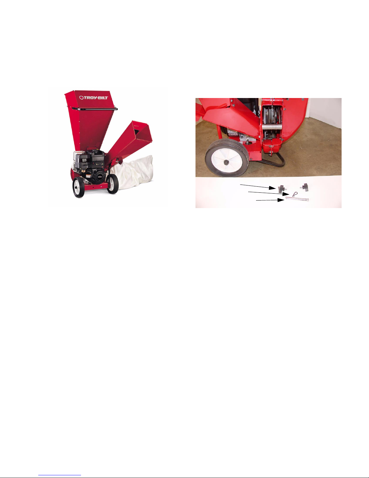
5.6. The flails can be inspected and replaced by
removing the roll pin retainer clip, roll pin and
clevis pin. See Figure 17.
IMPORTANT: The roll pin should be replaced if it
is removed for any reason.
Figure 15
Hex Cap Screws
Tube Support
Figure 16
Perimeter Hex Cap Screws
Figure 17
Flail
Roll Pin Retainer Clip
Roll Pin (Under Retainer)
Clevis Pin
 Loading...